

Page 1

Models
SP100W/SP100HK
SP200W/SP351W
Triplex Ceramic
Plunger Pump
Operating Instructions/
Repair and Service
Manual
Updated 03/18
Contents:
Installation Instructions: page 2
Pump Specications: pages 3-4
Parts List/Torque Specs.: page 5
Exploded View / Kits: page 6
Repair Instructions: pages 7-10
Recommended Spare Parts List: page 10
Pump Mounting Selection Guide: page 10
Dimensions: page 11
Warranty Information: back page
Page 2

Installation Instructions
Operation and Maintenance
Check oil level prior to starting and ensure
trouble-free water supply. Oil: Use only 23.7
ounces (0.7 liters) of Giant’s part number
01154 or ISO VG 220 GL4 (e.g. Aral Degol
BG220) or SAE 90 GL4 gear oil.
Initial change after 50 operating hours and
then every 500 operating hours, after 6
months operation in any case.
Caution! When operating in damp places or
with high temperature uctuations, oil must
be changed immediately, should condensate
(frothy oil) occur in the gear box.
Pressure in discharge line and in pump must
be at zero before any maintenance to the
pump takes place. Close up suction line.
Disconnect fuses to ensure that the driving
motor does not get switched on accidently.
Make sure that all parts on the pressure side
of the unit are vented and relled, with pressure at zero, before starting the pump.
In order to prevent air, or an air/water-mixture
being absorbed and to prevent cavitation occurring, the pump-NPSHR, positive suction
head and water temperature must be kept
under control.
Keep NPSH under control.
Maximum input pressure 145 PSI (10 bar)
Maximum suction head -4.35 PSI (-0.3 bar).
Safety Rules
Pump operation without safety valve as
well as any excess in temperature or speed
automatically voids the warranty . The safety
valve must be regulated in accordance with
the guidelines for liquid spraying units so that
the admissible operating pressure can not be
exceeded by more than 10%.
When the pump is in operation, the open
shaft end must be covered up by shaft protector (17), the driven shaft side and coupling
by a contact protector.
Cavitation and/or compression of gases
lead to uncontrollable pressure-kicks
which can ruin pump and unit parts and
also be dangerous to the operator or anyone standing nearby.
Giant Plunger Pumps are suitable for pumping clean water and other non-agressive or
abrasive media with a specic weight similar
to water.
Before pumping other liquids - especially
ammable, explosive and toxic media the pump manufacturer must, under all
circumstances, be consulted with regard
to the resistance of the pump material.
It is the responsibility of the equipment
manufacturer and/or operator to ensure
that all pertinent safety regulations are
adhered to.
2
Page 3

SP100W/SP100HK/SP200W/SP351W - Specications
U.S Measurements
Max.
Flow
Maximum
Pressure
Max.
Speed
Power
Required
Max
Temp
Plunger
Diameter
Stroke
Model GPM PSI RPM HP °F in in
SP100W 11.2 1885 1420 14.6 160 1.02 0.79
SP100HK 11.2 1885 1420 14.6 195 1.02 0.79
SP200W 9.6 2175 1420 14.4 160 0.94 0.79
SP351W 6.7 3190 1420 14.7 160 0.79 0.79
Metric Measurements
Max.
Flow
Model L/min bar RPM kW °C mm mm
SP100W 42.5 130 1420 10.9 70 26 20
SP100HK 42.5 130 1420 10.9 90 26 20
SP200W 36.2 150 1420 10.7 70 24 20
SP351W 25.2 220 1420 11.0 70 20 20
Maximum
Pressure
Max.
Speed
Power
Required
Max
Temp
Plunger
Diameter
Stroke
Consult the factory for special requirements that must be met if the
pump is to operate beyond one or more of the limits specied above.
PULLEY INFORMATION
Pulley selection and pump speed are based on
a 1725 RPM motor and “B” section belts. When
selecting desired GPM, allow for a ±5% tolerance
on pumps output due to variations in pulleys, belts
and motors among manufacturers.
1. Select GPM required, then select appropriate
motor and pump pulley from the same line.
2. The desired pressure is achieved by selecting
the correct nozzle size that corresponds with the
pump GPM.
Common Specications:
Crankcase Oil Capacity .......23.7 . oz. (0.7 L)
Inlet Ports ............................(2) 3/4”
Discharge Ports ...................(2) 3/4”
Crankshaft Mounting ...........Either Side
Shaft Rotation.....Top of Pulley Toward Fluid End
Weight .................................41.9 lbs. (19 kg)
HORSEPOWER INFORMATION
Horsepower ratings shown are the power re-
quirements for the pump. Gas engine power
outputs must be approximately twice the pump
power requirements shown above.
We recommend that a 1.1 service factor be specied when selecting an electric motor as the power
source. To compute specic pump horsepower
requirements, use the following formula:
(GPM X PSI) / 1450 = HP
3
Page 4

SP100W/SP100HK/SP200W/SP351W - Exploded View
4
Page 5

SP100W/SP100HK/SP200W/SP351W PARTS LIST
ITEM PART DESCRIPTIONS QTY
1 07294 Crankcase 1
2 06968 Oil Filler Cap with Gasket 1
3 07297 Cover, Crankcase 1
4 07298 O-Ring, Crankcase Cover 1
5 07299 Oil Dipstick Assembly 1
6 01009 O-Ring, Dip Stick 1
7 07186 Oil Sight Glass Assembly 1
9 01010 Screw, Crankcase Cover 4
10 01011-0400 Spring Washer, Cover Screw 4
11 07109 Oil Drain Plug 2
11A 06015 O-Ring 2
12 07302 Bearing Cover 2
13 07303 O-Ring, Bearing Cover 2
14 07459 Seal, Crankshaft 2
15 08388 Roller Bearing 2
15A 06962 Shim, 1.5mm 1-2
15B 07249** Shim 1
16 07114 Screw & Washer, Bearing Cover 6
17 05312 Shaft Protector 1
18 07309 Crankshaft 1
19 13331 Fitting Key 1
20 07310 Connecting Rod Assy. 3
20A 07311 Inner Hexagon Screw 3
20B 07122 Spring Washer 3
22 07315 Crosshead with Plunger Base 3
23 07314 Crosshead Pin 3
24A 07346 Ceramic Plunger, SP100W(HK) 3
24A 13452 Ceramic Plunger, SP200W 3
24A 07340 Ceramic Plunger, SP351W 3
24B 08399 Tension Screw 3
24C 07023 O-Ring 3
24D 07203 Support Ring 3
24E 07258 Copper Seal Washer 3
25 05289 Oil Scraper 3
26* 07318 Radial Shaft Seal 3
28 07319 Seal Retainer 2
29 07320 Manifold, SP100W(HK)/SP200W 1
29 07371 Manifold, SP351W 1
30 07335 Pressure Ring, SP100W(HK) 3
30 13366 Pressure Ring, SP200W 3
30 07268 Pressure Ring, SP351W 3
31 07336 V-Sleeve, SP100W(HK) 3
ITEM PART DESCRIPTIONS QTY
31 06083 V-Sleeve, SP200W 3
31 07322 V-Sleeve, SP351W 3
31A 11503 V-Sleeve, SP100HK 3
32 07337 Support Ring, SP100W 3
32 13367 Support Ring, SP200W 3
32 07270 Support Ring, SP351W 3
33 07338 Pressure Spring,
SP100W(HK)/SP200W 3
33 07275 Pressure Spring, SP351W 3
34 07325 Spring Retainer, Discharge 3
34A 07326-0100 Spring Retainer, Inlet 3
35 07312-0100 Valve Spring 6
36 07327 Valve Plate 6
37 06014 Valve Seat 6
38 06015 O-Ring, Valve Seat 6
39 07328 Valve Retainer, Inlet,
SP100W(HK)/SP200W 3
39 07383 Valve Retainer, Inlet, SP351W 3
39A 07329 Spacer 3
40 12057 O-Ring, Inlet Valve Retainer 3
41 07331 Plug, Inlet 3
42 07332 O-Ring, Inlet Plug 3
43 07213 Plug, Discharge,
SP100W(HK)/SP200W 3
43 06820 Plug, Discharge, SP351W 3
44 07214 O-Ring, Discharge Plug,
SP100W(HK)/SP200W 3
44 07035 O-Ring, Discharge Plug,
SP351W 3
45 07333 Stud Bolt 4
46 07158 Hex Nut, Stud Bolt 4
47 07159 Spring Washer, Stud Bolt 4
48 07347 Weep Return Plate, SP100W 1
48 13453 Weep Return Plate, SP200W 1
48 07343 Weep Return Plate, SP351W 1
49 07344 O-Ring, Weep Plate 1
50 07336 Weep Return Seal, SP100W 3
50 11503 Weep Return Seal, SP100HK 3
50 07688 Weep Return Seal, SP200W 3
50 06064 Weep Return Seal, SP351W 3
51 07349 Seal Support Ring, SP100W(HK) 3
51 07687 Seal Support Ring, SP200W 3
51 07345 Seal Support Ring, SP351W 3
*Older versions have three pieces (07318, 08059 and 08060) rather than a single piece oil seal.
**May not be present.
5
Page 6

SP100W/SP100HK/SP200W/SP351W - REPAIR KITS
Plunger Packing Repair #09077, SP100W
Item Part # Description Qty.
31 07336 V-Sleeve 3
40 12057 O-Ring, Inlet Valve Retainer 3
42 07332 O-Ring, Inlet Plug 3
49 07344 O-Ring, Weep Plate 1
50 07336 Weep Return Seal 3
Plunger Packing Repair #09798, SP200W
Item Part # Description Qty.
31 06083 V-Sleeve 3
40 12057 O-Ring, Inlet Valve Retainer 3
42 07332 O-Ring, Inlet Plug 3
49 07344 O-Ring, Weep Plate 1
50 07688 Weep Return Seal 3
Plunger Packing Repair #09076, SP351W
Item Part # Description Qty.
31 07322 V-Sleeve 3
40 12057 O-Ring, Inlet Valve Retainer 3
42 07332 O-Ring, Inlet Plug 3
49 07344 O-Ring, Weep Plate 1
50 06064 Weep Return Seal 3
Plunger Packing Repair Kit #09077-HK, SP100HK
Item Part # Description Qty.
31 07336 V-Sleeve 3
31A 11503 V-Sleeve 3
40 12057 O-Ring, Inlet Valve Retainer 3
42 07332 O-Ring, Inlet Plug 3
49 07344 O-Ring, Weep Plate 1
50 11503 V-Sleeve 3
Oil Seal Repair #09797
Item Part # Description Qty.
26 07318 Radial Shaft Seal 3
Complete Valve Kit #09814
Item Part # Description Qty.
34 07325 Discharge Spring Retainer 3
34A 07326-0100 Inlet Spring Retainer 3
35 07312-0100 Valve Spring 6
36 07327 Valve Plate 6
37 06014 Valve Seat 6
38 06015 O-Ring, Valve Seat 6
40 12057 O-Ring, Inlet Valve Retainer 3
42 07332 O-Ring, Inlet Plug 3
44 07214 O-Ring,
SP100W(HK)/SP200W 3
44 07035 O-Ring, SP351W 3
Inlet Valve Kit #09069
Item Part # Description Qty.
34A 07326-0100 Inlet Spring Retainer 3
35 07312-0100 Valve Spring 3
36 07327 Valve Plate 3
37 06014 Valve Seat 3
38 06015 O-Ring, Valve Seat 3
40 12057 O-Ring, Inlet Valve Retainer 3
42 07332 O-Ring, Inlet Plug 3
Discharge Valve Kit #09068
Item Part # Description Qty.
34 07325-0100 Discharge Spring Retainer 3
35 07312-0100 Valve Spring 3
36 07327 Valve Plate 3
37 06014 Valve Seat 3
38 06015 O-Ring, Valve Seat 3
44 07214 O-Ring,
SP100W(HK)/SP200W 3
44 07035 O-Ring, SP351W 3
SP100W/SP100HK/SP200W/SP351W TORQUE SPECIFICATIONS
Position Part# Description Torque Amount
7 07186 Oil Sight Glass Assembly (Loctite 5910) 106 in.-lbs. (12 Nm)
9 01010 Screw 221 in.-lbs. (25 Nm)
11 07109 Oil Drain Plug 29 ft.-lbs. (40 Nm)
16 07114 Screw and Washer 132 in.-lbs. (15 Nm)
20A 07311 Inner Hexagon Screw 22 ft.-lbs. (30 Nm)
24B 08399 Tension Screw, SP100(HK)/SP200W (Loctite 243) 247 in.-lbs. (28 Nm)
26 07318 Radial Shaft Seal (Loctite 403)
41/43 07331/07213 Plug, Inlet and Discharge, SP100W(HK)/SP200W 51 ft.-lbs. (70 Nm)
41/43 07331/06800 Plug, Inlet and Discharge, SP351W 59 ft.-lbs. (80 Nm)
45 07333 Stud Bolt (Loctite 270)
46 07158 Nut, Stud Bolt 200 in.-lbs. (22.5 Nm)
6
Page 7

REPAIR INSTRUCTION - SP100W/SP100HK/SP200W/SP351W PUMPS
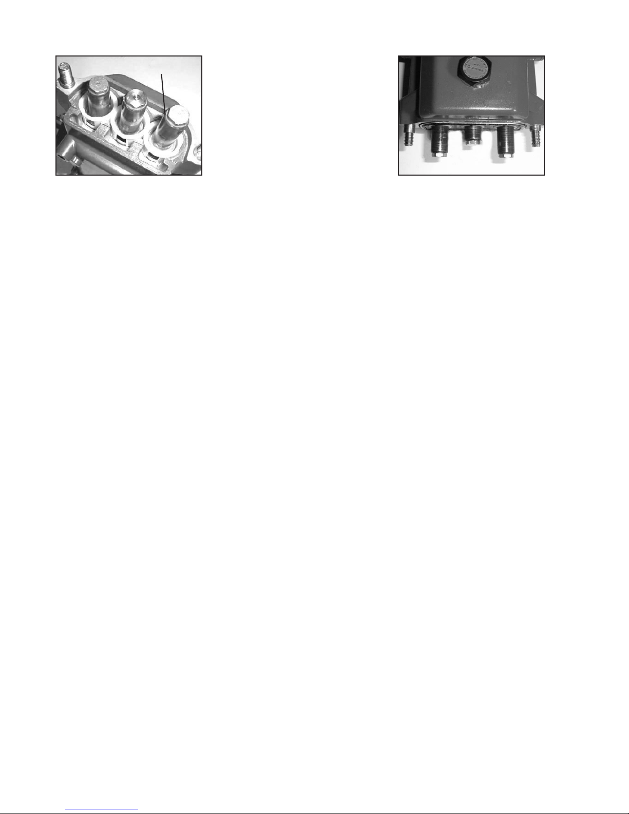
41A 44 34 35 36
1. With a 22mm socket, remove
the three discharge (43)
and three inlet (41) manifold
plugs.
3. Use a small slide hammer
to remove valve seats (37)
from manifold (29). Inspect
valve plate (36) and valve
seats (37) for wear. If excessive pitting is seen, replace
the worn parts. Check valve
seat o-ring (38) for wear and
replace as necessary.
2. Check o-ring (44) for wear and replace as necessary. Remove the
discharge spring retainer (34), valve spring (35), and valve plate
(36).
4. Drain the oil from the pump.
Turn the pump over to remove
the four manifold stud nuts
(46) with a 19mm wrench.
5. Tap the back of the valve casing
(29) with a rubber mallet.
6. Remove the inlet valve retainer assembly (34A-39)
NOTE: Contact Giant Industries for Service School Information. Phone: (419)-531-4600
40 36 35 34A
7. Remove the o-ring, (40), valve plate (36), valve spring (35), spring
retainer (34A). Check valve retainer o-ring (40) for wear.
7A. Reassembly valve assemblies and install into manifold (29). Tighten
plugs to 51 ft.-lbs. (70 Nm) for SP100W(HK)/SP200W or 59 ft.-lbs.
(80 Nm) for SP351W.
7
Page 8

REPAIR INSTRUCTION - SP100W/SP100HK/SP200W/SP351W PUMPS
8. With a valve puller remove
the valve seat (37) and o-ring
(38) replace if worn. If excessive pitting is seen, replace
the worn parts. Check valve
seat o-ring (38) for wear and
replace as necessary.
10. With a at headed screw-
driver remove the weep return
plate (48). Remove the o-ring
(49) and check for wear.
30 31 32 33 39A
9. Remove the spacer (39A), pressure spring (33), support ring (32
or 31A for SP100HK), v-sleeve (31), and pressure ring (30), from
the manifold (29) and check for wear.
31A for SP100HK
49
50
51
11. Inspect seals (50), seal sup-
port ring (51) and O-ring (49)
and replace as necessary.
12. Inspect ceramic plunger
(24A) tips for wear. If necessary, replacement of the
ceramic plungers may be accomplished by removing the
plunger bolt assemblies (24)
with a 13mm wrench. Ce-
ramic plungers should now
slide off the stainless steel
plunger base (22). Exces-
sive resistance to plunger
removal may be overcome
by heating the stainless steel
plunger base. This will melt
any excess loc-tite beneath
the ceramic plunger allowing
easy removal.
8
Page 9
REPAIR INSTRUCTION - SP100W/SP100HK/SP200W/SP351W PUMPS
24E
13. Replace copper ring
(24E) onto plunger bolt
(24B). Slide plunger bolt
assembly (24) into ceramic
plunger (24A). Apply a light
lm of loc-tite to plunger bolt
threads and place plunger
assembly onto stainless
steel plunger base (22)
and tighten to 310 in.-lbs.
(35 Nm) for SP100W(HK)/
SP200W and 265 in.-lbs. (30
Nm) for SP351W.
Gear End Disassembly
14. To replace plunger oil
seals (26), proceed to “Gear
End Disassembly” section
below. Otherwise, continue as
described below.
15. Before replacing pump
manifold (29), rst rotate
crankshaft (18) until two
outside plungers (24A) extend
evenly forward. Next lubricate v-sleeves (50) in the rear
v-sleeve housing (48) and
slide housing over plungers.
Lubricate ceramic plungers
with a light lm of oil. Carefully
and evenly slide manifold over
plungers and press manifold
rmly against crankcase (1).
Replace manifold stud bolts
(45), washers (47) and nut
(46) and tighten to 59 ft.-lbs.
(80 Nm).
16. Remove the crankcase cover screws (9). Inspect the crankcase cover o-ring (4) for wear. Replace if necessary.
17. Inspect the dipstick (5) vent hole for signs of clogging. Clean if necessary.
18. To remove the crankshaft (18), rst remove the bearing cover plates (12). Remove the key (19).
19. With a 5 mm allen wrench remove the connecting rod screws (21) and rear portion of connecting rod assemblies
(20). Push the connecting rod (20) and plunger rod (22) down as far as possible into the crankcase housing.
20. Hold the pump rear assembly with a wooden xture, or other suitable device, in order to secure it while removing
the crankshaft (18). Using a plastic mallet, tap the crankshaft from one side while turning it from the other side.
The turning insures that during this sequence the crankshaft does not become wedged against the front portion
of the connecting rods (20). The far side bearing (15) will remain in the crankcase (1). When free, the crankshaft can be removed by hand. The opposite side crankshaft seal (14) will be removed by this procedure. It is
important that you turn the crankshaft (18) constantly while tapping from the opposite end to avoid any
binding. The crankshaft bearing (15) remains on the crankshaft as it is removed. If necessary, use a bear-
ing puller to remove the crankshaft bearing (15).
21. Remove the front portion of the connecting rods (20) and plunger base assembly (22) from the rear of the pump
by pulling straight out of the crankcase crosshead guides. Notice that the connecting rod (20) halves are
numbered or colored. Connecting rods must be positioned with their numbers or colors on the upper
left-hand side, in the same numerical sequence as when they were removed.
22. Using a dowel and a rubber mallet, tap the oil seals (26) out from the rear of crankcase (1). The area onto which
the oil seal rests should be clean and dry. Put a small drop of loc-tite on the oil seals and place into crankcase
with lips facing the rear of the pump.
23. To remove the crosshead pin (23) from the crosshead (22), the assembly should be positioned on a wooden
xture to avoid damage to crosshead. Drive out the pin on opposite side of mark located on the crosshead. On
those pumps without mark on crosshead, drive out pin by tapping on tapered side of pin.
24. To remove the bearing (15) remaining in the crankcase (1), insert small end of Giant bearing tool and tap with
a rubber mallet until bearing and seal (14) are completely removed. The bearing can only be removed from
the inside by inserting the Giant Bearing Tool through the opposite side of the crankcase. The crosshead
guide in the crankcase should be inspected for possible damage.
9
Page 10

Check Daily Weekly 50 Hrs.
Every
500 hrs
Every
1500 hrs
Every
3000 hrs
Oil Level/Quality X
Oil Leaks X
Water Leaks X
Belts, Pulley X
Plumbing X
Oil Change (1 quart) p/n 01154 X X
Plunger Packing Kit (1 kit/pump)
See page 6 for kit list
X
Valve Assembly Kit (1 kit/pump)
See page 6 for kit list
X
Oil Seal Kit (1 kit/pump)
See page 6 for kit list
X
Preventative Maintenance Check List & Recommended Spare Parts List
Recommended Spare Parts
REPAIR INSTRUCTION - SP100W/SP100HK/SP200W/SP351W PUMPS
25. To reassemble, place the far bearing (15) in the crankcase (1) bearing housing and with the Giant Bearing
tool as a driver, tap into the crankcase using a rubber mallet.
26. Insert the far side crankshaft oil seal (14) with the Giant Bearing Tool making sure it is rmly seated and well
oiled. Always make sure that the crankshaft seal lip does not show signs of wear and that the garter spring
is rmly in place on the seal before reinserting into the pump. Replace the bearing cover (12) and o-ring (13)
and tighten securely.
27. Replace the front portion of the connecting rod (20) and plunger rod/ crosshead assembly (22) by press-tting
the crosshead pin (23). Make sure to insert the beveled edge of the crosshead pin into crosshead. If the
crosshead has a mark, install pin from marked side. The crosshead pin (23) should not extend beyond
either side of the crosshead (22) in order to prevent damage to the crosshead bore of the crankcase
(1).
28. Place each crosshead/ plunger assembly into the pump making sure that all of the parts are well oiled before
insertion into the crankcase (1). Notice that the connecting rod (20) halves are numbered or colored.
Connecting rods must be positioned with their numbers or colors on the upper left-hand side, in the
same numerical sequence as when they were removed.
29. Replace near side bearing (15) on crankshaft by using the Giant Bearing Tool and mallet to tap into place.
Take the crankshaft (18) end with the bearing (15) and insert the other end through the bearing housing and
tap with a rubber mallet until the bearing is seated.
30. When reassembling the connecting rods (20), note that the connecting rod halves are numbered or colored
and that the numbers or colors must be matched and aligned. Torque the connecting rod bolts to 310 in.-lbs.
(35 Nm).
31. Insert the near side crankshaft oil seal (14) with the Giant Bearing Tool making sure it is rmly seated and well
oiled. Replace the bearing cover (12) and o-ring (13) and tighten securely.
See steps 7A-15 above for re-installing uid end onto the gear end.
32. Fill the crankcase (1) with 24 oz. (0.7 liters) of Giant Industries’ oil and check the oil level with the dipstick (5).
Proper level is center of two lines. Reinstall the pump into your system.
7
7
7
Pump Mounting Selection Guide
Bushings
07175 - 28 mm Tapered H Bushing
Pulley & Sheaves
01055 - 9.75” Cast Iron 2 gr. - AB Section
01062 - 7.75” Cast Iron - 2 gr. - AB Section
Rails
07358 - Plated Steel Channel Rails
(L=9.18” x W=1.88” x H=3.00”)
10
Page 11

SP100W/SP100HK/SP200W/SP351W - DIMENSIONS
INCHES (mm)
11
Page 12

GIANT INDUSTRIES LIMITED WARRANTY
Giant Industries, Inc. pumps and accessories are warranted by the manufacturer to be free from
defects in workmanship and material as follows:
1. For portable pressure washers and self-service car wash applications, the discharge
manifolds will never fail, period. If they ever fail, we will replace them free of charge.
Our other pump parts, used in portable pressure washers and in car wash applications,
aaaaaaaaaaaare warranted for ve years from the date of shipment for all pumps used in NON-
SALINE, clean water applications.
2. One (1) year from the date of shipment for all other Giant industrial and consumer
pumps.
3. Six (6) months from the date of shipment for all rebuilt pumps.
4. Ninety (90) days from the date of shipment for all Giant accessories.
This warranty is limited to repair or replacement of pumps and accessories of which the manufacturer’s evaluation shows were defective at the time of shipment by the manufacturer. The following
items are NOT covered or will void the warranty:
1. Defects caused by negligence or fault of the buyer or third party.
2. Normal wear and tear to standard wear parts.
3. Use of repair parts other than those manufactured or authorized by Giant.
4. Improper use of the product as a component part.
5. Changes or modications made by the customer or third party.
6. The operation of pumps and or accessories exceeding the specications set forth
in the Operations Manuals provided by Giant Industries, Inc.
Liability under this warranty is on all non-wear parts and limited to the replacement or repair of those
products returned freight prepaid to Giant Industries which are deemed to be defective due to workmanship or failure of material. A Returned Goods Authorization (R.G.A.) number and completed
warranty evaluation form is required prior to the return to Giant Industries of all products under
warranty consideration. Call (419)-531-4600 or fax (419)-531-6836 to obtain an R.G.A. number.
Repair or replacement of defective products as provided is the sole and exclusive remedy provided
hereunder and the MANUFACTURER SHALL NOT BE LIABLE FOR FURTHER LOSS, DAMAGES,
OR EXPENSES, INCLUDING INCIDENTAL AND CONSEQUENTIAL DAMAGES DIRECTLY OR
INDIRECTLY ARISING FROM THE SALE OR USE OF THIS PRODUCT.
THE LIMITED WARRANTY SET FORTH HEREIN IS IN LIEU OF ALL OTHER WARRANTIES OR
REPRESENTATION, EXPRESS OR IMPLIED, INCLUDING WITHOUT LIMITATION ANY WARRANTIES OR MERCHANTABILITY OR FITNESS FOR A PARTICULAR PURPOSE AND ALL SUCH
WARRANTIES ARE HEREBY DISCLAIMED AND EXCLUDED BY THE MANUFACTURER.
GIANT INDUSTRIES, INC., 900 N. Westwood Ave., Toledo, Ohio 43607
Phone: (419) 531-4600 FAX (419) 531-6836, www.giantpumps.com
Copyright 2018 Giant Industries, Inc.
03/18 SP100W(HK)_SP200W_SP351W.indd
 Loading...