

Page 1
Model
SP100W
Triplex Ceramic
Plunger Pump
Operating Instructions/
Repair and Service
Manual
Updated 8/97
Contents:
Installation Instructions: page 2
Pump Specifications: page 3
Parts List/Torque Specs.: page 4
Exploded View / Kits: page 5
Trouble Shooting: page 6
Repair Instructions: page 7
Dimensions: back page
Warranty Information: back page
Page 2
INSTALLATION INSTRUCTIONS
Installation of the Giant Industries, Inc.,
pump is not a complicated procedure, but
there are some basic steps common to all
pumps. The following information is to be
considered as a general outline for installation. If you have unique requirements, please
contact Giant Industries, Inc. or your local
distributor for assistance.
1. The pump should be installed flat on a base to
a maximum of a 15 degree angle of inclination
to ensure optimum lubrication.
2. The inlet to the pump should be sized for the
flow rate of the pump with no unnecessary
restrictions that can cause cavitation. Teflon
tape should be used to seal all joints. If pumps
are to be operated at temperatures in excess of
1200 F, it is important to insure a positive head
to the pump to prevent cavitation.
3. The discharge plumbing from the pump
should be properly sized to the flow rate to
prevent line pressure loss to the work area. It is
essential to provide a safety bypass valve
between the pump and the work area to protect
the pump from pressure spikes in the event of a
blockage or the use of a shut-off gun.
4. Use of a dampener is necessary to minimize
pulsation at drive elements, plumbing, connections, and other system areas. The use of a
dampener with Giant Industries, Inc. pumps is
optional, although recommended by Giant
Industries, Inc. to further reduce system pulsation. Dampeners can also reduce the severity of
pressure spikes that occur in systems using a
shut-off gun. A dampener must be positioned
downstream from the unloader.
5. Crankshaft rotation on Giant Industries, Inc.
pumps should be made in the direction designated by the arrows on the pump crankcase.
Reverse rotation may be safely achieved by
following a few guidelines available upon
request from Giant Industries, Inc. Required
horsepower for system operation can be obtained from the charts on pages 3-6.
6. Before beginning operation of your pumping
system, remember: Check that the crankcase
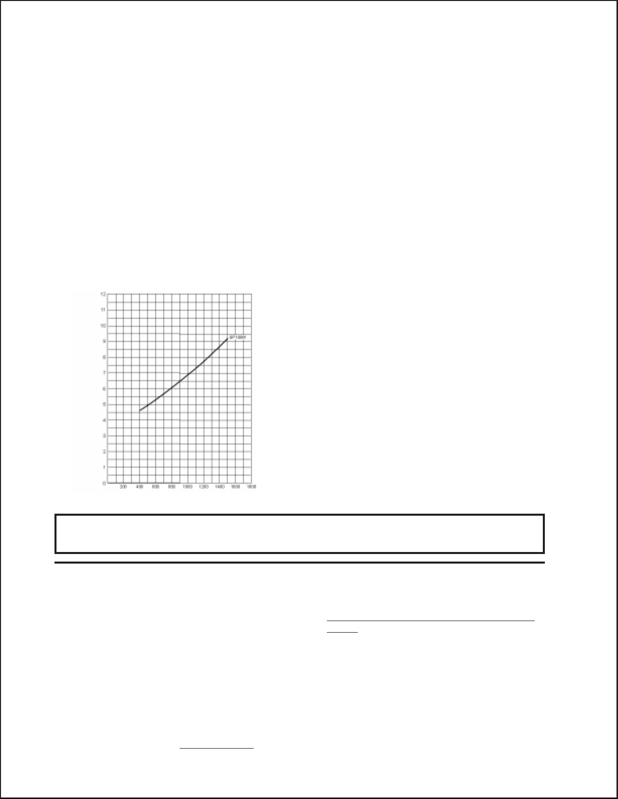
NPSHR (FT-HEAD)
and seal areas have been properly lubricated per
recommended schedules. Do not run the pump
dry for extended periods of time. Cavitation will
result in severe damage. Always remember to
check that all plumbing valves are open and that
pumped media can flow freely to the inlet of the
RPM
pump.
Finally, remember that high pressure operation in a pump system has many advantages. But, if it is used
carelessly and without regard to its potential hazard, it can cause serious injury.
IMPORTANT OPERATING CONDITIONS
Failure to comply with any of these conditions invalidates the warranty.
1. Prior to initial operation, add oil to the
crankcase so that oil level is between the two
device must be installed in the discharge of the
system.
lines on the oil dipstick. DO NOT OVERFILL.
3. Acids, alkalines, or abrasive fluids cannot be
SAE 80W-140 Gear Oil
pumped unless approval in writing is obtained
before operation from Giant Industries, Inc.
Crankcase oil should be changed after the
first 50 hours of operation, then at regular
intervals of 500 hours or less depending on
operating conditions.
4. Run the pump dry approximately 10 seconds
to drain the water before exposure to freezing
temperatures.
2. Pump operation must not exceed rated
pressure, volume, or RPM.
A pressure relief
Page 3
Specifications
9.7
Model SP100W
Volume ........................................................................................................ Up to 11.2 GPM
Discharge Pressure ..................................................................................... Up to 2000 PSI
Inlet Pressure .............................................................................................. Up to 90 PSI
Maximum Speed of Crankshaft .................................................................. Up to 1420 RPM
Plunger Diameter ........................................................................................ 26mm
Stroke .......................................................................................................... 20mm
Crankcase Oil Capacity .............................................................................. 24 fl.oz.
Temperature of Pumped Fluids .................................................................. Up to 160
Inlet Ports ................................................................................................... (2) 3/4" NPT
Discharge Ports .......................................................................................... (2) 3/8" NPT
Crankshaft Mounting .................................................................................. Either Side
Shaft Rotation ................................................................................ Top of Pulley Towards Fluid End
Weight......................................................................................................... 31 lbs.
Crankshaft Diameter................................................................................... 28mm
Consult the factory for special requirements that must be met if the pump is to
operate beyond one or more of the limits specified above.
o
F
PULLEY INFORMATION
Pulley selection and pump speed are based on a 1725
RPM motor and "B" section belts. When selecting
desired GPM, allow for a ±5% tolerance on pumps
output due to variations in pulleys, belts and motors
among manufacturers.
1. Select GPM required, then select appropriate
motor and pump pulley from the same line.
2. The desired pressure is achieved by selecting the
correct nozzle size that corresponds with the pump
GPM.
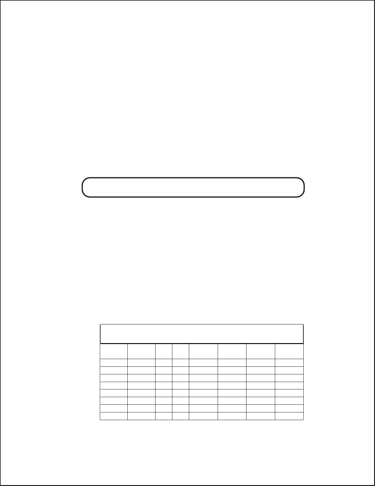
SP100W PULLEY SELECTION & HORSEPOWER
REQUIREMENTS
PUMP
PULLEY
9.75" 4.15" 700 5.5 4.5 5.7 7.2 7.5
9.75" 4.70" 800 6.3 5.2 6.5 8.2 8.6
9.75" 5.25" 900 7.1 5.8 7.3 9.2 9.7
9.75" 5.50" 950 7.5 6.1 7.7
9.75" 5.80" 1000 7.9 6.5 8.1 10.2 10.8
9.75" 6.90" 1200 9.4 7.7 9.7 12.3 12.9
9.75" 7.45" 1300 10.2 8.4 10.5 13.3 14.0
9.75" 8.10" 1420 11.2 9.2 11.5 14.5
MOTO R
PULLEY
RPM GPM 1200 PSI 1500 PSI 1900 PSI 2000 PSI
HORSEPOWER INFORMATION
Horsepower ratings shown are the power requirements for the pump. Gas engine power outputs must
be approximately twice the pump power requirements shown above.
We recommend that a 1.1 service factor be specified
when selecting an electric motor as the power source.
To compute specific pump horsepower requirements,
use the following formula:
(GPM X PSI) / 1460 = HP
10.2
Page 4

SP100W PARTS LIST
ITEM PART DESCRIPTIONS QTY
1 07294 Crankcase 1
2 07295 Oil Filler Cap 1
2A 07296 Gasket, Oil Filler Cap 1
3 07297 Cover, Crankcase 3
4 07298 O-Ring, Crankcase Cover 1
5 07299 Oil Dipstick 1
6 01009 O-Ring, Dip Stick 1
7 07186 Oil Sight Glass 1
8 07187 Gasket, Oil Sight Glass 1
9 01010 Screw, Crankcase Cover 4
10 01011 Spring Washer, Cover Screw 4
11 07109 Oil Drain Plug 2
11A 07182 Gasket for Oil Drain Plug 2
12 07302 Bearing Cover 2
13 07303 O-Ring, Bearing Cover 2
14 07459 Seal, Crankshaft 2
15 07306 Roller Bearing 2
16 07114 Screw & Washer,
Bearing Cover 6
17 07308 Shaft Protector 1
18 13349 Crankshaft 1
19 07252 Woodruff Key 1
20 07310 Connecting Rod Assy. 3
21 07311 Screw & Washer, Conn. Rod 3
22 07315 Crosshead with Plunger Base 3
23 07314 Crosshead Pin 3
24A 07346 Ceramic Plunger, SP100W 3
24B 07360 Bolt Assembly, SP100W
(Items 24B, 24C, 24D, 24E) 3
24C 07023 O-Ring, Bolt Assy. (Viton) 3
24D 07203 Support Ring 3
24E 07258 Copper Seal Washer 3
ITEM PART DESCRIPTIONS QTY
25 07317 Flinger 3
27 08058
27A 08059 O-Ring 3
27B 08060 Seal Housing 3
28 07319 Shim, Stud 2
29 07320 Manifold, SP100W 1
30 07335 Pressure Ring 3
31 07336 V-Sleeve 3
32 07337 Support Ring 3
33 07338 Pressure Spring 3
34 07325-0100 Spring Retainer, Discharge 3
34A 07326-0100 Spring Retainer, Inlet 3
35 07312-0100 Valve Spring 6
36 07327 Valve Plate 6
37 06014 Valve Seat 6
38 06015 O-Ring, Valve Seat 6
39 07328 Valve Retainer, Inlet 3
39A 07329 Spacer 3
40 12057 O-Ring, Inlet Valve Retainer 3
41 07331 Plug, Inlet 3
41A 07213 Plug, Discharge 3
42 07332 O-Ring, Inlet Plug 3
42A 07214 O-Ring, Discharge Plug, 3
43 07333 Stud Bolt 4
44 07158 Hex Nut, Stud Bolt 4
45 07159 Spring Washer, Stud Bolt 4
46 07347 Weep Return Plate 1
47 07344 O-Ring, Weep Plate 1
48 07348 Weep Return Seal 3
49 07349 Seal Support Ring 3
1
Oil Seal 3
1
Earlier (non-weep) versions only had an oil seal. They did not have items 27, 27A and 27B.
SP100W TORQUE SPECIFICATIONS
Position Part# Description Torque Amount
24B 07360 Tension Screw 228 in.-lbs.
41 or 41A 07331 or 07213 Plug, Inlet and Discharge 103 ft.-lbs.
44 07158 Nut, Stud Bolt 52 ft.-lbs.
Page 5

SP100W EXPLODED VIEW
SP100W REPAIR KITS
Plunger Packing Repair #09077
Qty. Part # Description
3 07336 V-Sleeve
Ceramic Plunger Kit #09079
Qty. Part # Description
3 07346 Ceramic Plunger
3 07360 Bolt Assy. (24B-E)
3 07317 Flinger
Weep Repair Kit #09075
Qty. Part # Description
1 07344 O-Ring,Weep Return
Plate
3 07348 Seal, Weep Return
Inlet Valve Kit #09069
Qty. Part # Description
3 07326-0100 Inlet Spring Retainer
3 07312-0100 Valve Spring
3 07327 Valve Plate
3 06014 Valve Seat
3 06015 O-Ring, Valve Seat
3 12057 O-Ring, Inlet Valve Retainer
3 07332 O-Ring, Inlet Plug
Discharge Valve Kit #09068
Qty. Part # Description
3 07214 Discharge Plug O-Ring,
3 07325-0100 Spring Retainer, Discharge
3 07312-0100 Valve Spring
3 07327 Valve Plate
3 06014 Valve Seat
3 06015 O-Ring, Valve Seat
Page 6

PUMP SYSTEM MALFUNCTION
MALFUNCTION
The Pressure and/
or the Delivery
Drops
Water in crankcase
Noisy Operation
CAUSE
Worn packing seals
Broken valve spring
Belt slippage
Worn or Damaged nozzle
Fouled discharge valve
Fouled inlet strainer
Worn or Damaged hose
Worn or Plugged relief valve on pump
Cavitation
Unloader
High humidity
Worn seals
Worn bearings
Cavitation
REMEDY
Replace packing seals
Replace spring
Tighten or Replace belt
Replace nozzle
Clean valve assembly
Clean strainer
Repair/Replace hose
Clean, Reset, and Replace worn parts
Check suction lines on inlet of
pump for restrictions
Check for proper operation
Reduce oil change interval
Replace seals
Replace bearings, Refill crankcase
oil with recommended lubricant
Check inlet lines for restrictions
and/or proper sizing
Rough/Pulsating
Operation with
Pressure Drop
Pressure Drop at
Gun
Excessive Leakage
Worn packing
Inlet restriction
Accumulator pressure
Unloader
Cavitation
Restricted discharge plumbing
Worn plungers
Worn packing/seals
Excessive vacuum
Cracked plungers
Inlet pressure too high
Replace packing
Check system for stoppage, air
leaks, correctly sized inlet
plumbing to pump
Recharge/Replace accumulator
Check for proper operation
Check inlet lines for restrictions
and/or proper size
Re-size discharge plumbing to
flow rate of pump
Replace plungers
Adjust or Replace packing seals
Reduce suction vacuum
Replace plungers
Reduce inlet pressure
High Crankcase
Temperature
Wrong Grade of oil
Improper amount of oil in crankcase
Giant oil is recommended
Adjust oil level to proper amount
Page 7

REPAIR INSTRUCTION - SP100W SERIES
41A 44 34 35 36
1. With a 22mm socket, remove
the three discharge (43) and
three inlet (41) manifold plugs.
7. Use a small slide hammer to
remove valve seats (37) from
manifold (29). Inspect valve
plate (36) and valve seats (37)
for wear. If excessive pitting
is seen, replace the worn parts.
Check valve seat o-ring (38)
for wear and replace as necessary.
2. Check o-ring (44) for wear and replace as necessary. Remove the
discharge spring retainer (34), valve spring (35), and valve plate (36).
8. Drain the oil from the pump.
Turn the pump over to remove
the four manifold stud nuts
(46) with a 19mm wrench.
9. The front oil seal (31A) can
now be removed by inserting a
screwdriver through the rear
of the retainer and tapping the
seal out through the front of
the retainer. Remove any excess old loc-tite from retainer.
To replace oil seal, apply a
light film of loc-tite around
outside edges of seal. Tap seal
firmly into the retainer with a
wooden dowel making certain
that the spring side of the seal
is installed first and that the
seal sits squarely in the retainer.
NOTE: Contact Giant Industries for Service School Information. Phone: (419)-531-4600
Page 8

SP100W DIMENSIONS
GIANT INDUSTRIES LIMITED WARRANTY
Giant Industries, Inc. pumps and accessories are warranted by the manufacturer to be free from
defects in workmanship and material as follows:
1. Five (5) years from the date of shipment for all pumps used in portable pressure
washers with NON-SALINE, clean water applications.
2. Two (2) years from the date of shipment for Giant pumps used in car wash applications.
3. One (1) year from the date of shipment for all other Giant industrial and consumer
pumps.
4. Six (6) months from the date of shipment for all rebuilt pumps
5. Ninety (90) days from the date of shipment for all Giant accessories.
This warranty is limited to repair or replacement of pumps and accessories of which the manufacturers
evaluation shows were defective at the time of shipment by the manufacturer. The following items
are NOT covered or will void the warranty:
1. Defects caused by negligence or fault of the buyer or third party.
2. Normal wear and tear to standard wear parts.
3. Use of repair parts other than those manufactured or authorized by Giant.
4. Improper use of the product as a component part.
5. Changes or modifications made by the customer or third party.
6. The operation of pumps and or accessories exceeding the specifications set forth
in the Operations Manuals provided by Giant Industries, Inc.
Liability under this warranty is on all non-wear parts and limited to the replacement or repair of those
products returned freight prepaid to Giant Industries which are deemed to be defective due to
workmanship or failure of material. A Returned Goods Authorization (R.G.A.) number and completed
warranty evaluation form is required
warranty consideration. Call (419)-531-4600 or fax (419)-531-6836 to obtain an R.G.A. number.
Repair or replacement of defective products as provided is the sole and exclusive remedy provided
hereunder and the MANUFACTURER SHALL NOT BE LIABLE FOR FURTHER LOSS, DAMAGES,
OR EXPENSES, INCLUDING INCIDENTAL AND CONSEQUENTIAL DAMAGES DIRECTLY OR
INDIRECTLY ARISING FROM THE SALE OR USE OF THIS PRODUCT.
THE LIMITED WARRANTY SET FORTH HEREIN IS IN LIEU OF ALL OTHER WARRANTIES OR
REPRESENTATION, EXPRESS OR IMPLIED, INCLUDING WITHOUT LIMITATION ANY WARRANTIES OR MERCHANTABILITY OR FITNESS FOR A PARTICULAR PURPOSE AND ALL SUCH
WARRANTIES ARE HEREBY DISCLAIMED AND EXCLUDED BY THE MANUFACTURER.
prior to the return to Giant Industries of all products under
8/97 SP100.PM5
 Loading...