

Giant P200A Series, P225, P226, P228, P223 Operating Instructions/ Repair And Service Manual

Triplex Ceramic
Plunger Pump
Operating Instructions/
Series
Repair and Service
Manual
P200A-16mm versions
For Models:
P225
P226
P223
P228
Updated 03/19
Contents:
Installation Instructions: page 2
Pump Specications: pages 3
Exploded View: page 4
Parts List: page 5
Kits & Torque Specications: page 5
Recommended
Spare Parts List: page 7
Repair Instructions: pages 6-7
Dimensions: back page
Warranty Information: back page

INSTALLATION INSTRUCTIONS
Required NPSH refers to water: specic weight
1kg/dm3, viscosity 1°E at maximum permissible
revolutions.
Operation and Maintenance
Check oil level prior to starting and ensure a
trouble-free water supply.
Important! If there is a danger of frost, the
water in the pump and in the pump ttings (particularly the unloader valve) must be emptied.
The second discharge port can also be used
and the pump run “dry” for 1-2 minutes for this
purpose.
Oil: Use only SAE 20W-50 (p/n 01153). Use
7.5 uid ounces (0.22 L) for short crankcase
covers and 9.0 uid ounces (0.27 L) for extend-
ed crankcase covers.
Initial change after 50 operating hours and then
every 500 operating hours, after 1 year if used
less.
Caution when operating in damp places or
with high temperature uctuations. Oil must
be changed immediately, should condensate
(frothy oil) occur in the gear box.
Keep NPSH under control.
Maximum input pressure 145 PSI (10 bar),
maximum suction head -4.35 PSI (-0.3 bar).
Make sure suction pulsation is sufciently
dampened - water column resonance must be
avoided.
When the pump is in operation, the drive shaft
end and the coupling must be covered up by
either a contact-protector or by a coupling bell.
Pressure in discharge line and in pump must
be at zero before any maintenance to the
pump takes place. Close up suction line. Disconnect fuses to ensure that the driving motor
does not get switched on accidentally.
Make sure that all parts on the pressure side
of the unit are vented before starting the pump.
In order to preven air, or an air-water mixture
being absorbed and to prevent cavitation occurring, the pump NPSHR suction head and
water temperature must be kept under control.
Cavitation and/or compression of gases
lead to uncontrollable pressure kicks which
can ruin pump and unit parts and also be
dangerous to the operator or anyone standing nearby.
Giant Plunger Pumps are suitable for pumping clean water and other non-agressive or
abrasive media with a specic weight similar to
water.
Before pumping other liquids - especially
inammable, explosive and toxic media -
the pump manufacturer must under all circumstances be consulted with regard to the
resistance of the pump material. It is the responsibility of the equipment manufacturer
and/or operator to ensure that all pertinent
safety regulations are adhered to.
Safety Rules
Pump operation witout safety valve as well
as any excess in temperature or speed limits,
automatically voids the warranty. The safety
valve must be regulated in accordance with the
guidelines for liquid spraying units so that the
maximum admissible operating pressure can
not be exceeded by more than 10%.
2

Specications
ModelS P225/P226/P223/P228
Max.
Max.
Flow
Flow
Model GPM l/min PSI bar RPM PSI bar in mm in mm BHP kW
P225 0.9 3.4 2000/3000 140/200 1750 145 10 0.63 16 0.13 3.4 1.9 1.4
P226 1.5 5.7 2000/3000 140/200 1750 145 10 0.63 16 0.22 5.5 3.1 2.3
P225 1.6 6.1 2000/3000 140/200 3450 145 10 0.63 16 0.13 3.4 3.3 2.5
P223 1.7 6.4 2000/3000 140/200 1750 145 10 0.63 16 0.25 6.3 3.5 2.6
P228 1.8 6.8 2000/3000 140/200 1750 145 10 0.63 16 0.28 7.0 3.7 2.8
P225 2.8 10.6 2000/3000 140/200 3450 145 10 0.63 16 0.22 5.5 5.8 4.3
P223 3.0 11.4 2000/3000 140/200 3450 145 10 0.63 16 0.25 6.3 6.2 4.6
P228 3.3 12.7 2000/3000 140/200 3450 145 10 0.63 16 0.28 7.0 6.9 5.2
*
Positive inlet pressure required- Make sure that suction pulsation is sufciently dampened-water column resonance must be avoided.
Common Specications U.S. Metric
Max. Temperature of Pumped Fluids .....................160o F .......................................................................70o C
Inlet Ports .................................................................................................................................... (2) 1/2” BSP
Discharge Ports ........................................................................................................................... (2) 3/8” BSP
Shaft Rotation ............................................................................................... Top of Pulley Towards Fluid End
Crankshaft Diameter..............................................0.98” ...................................................................... 24 mm
Key Width .............................................................. 0.31” ........................................................................ 8 mm
Shaft Mounting ..................................................................................................... Right Side Facing Manifold
Weight ...................................................................11.7 lbs. .................................................................. 5.3 Kg
Crankcase Oil Capacity ......................................... 7.5 .oz. ............................................................ 0.22 Liter
Extended Crankcase Oil Capacity ......................... 9.0 .oz. ............................................................ 0.27 Liter
Volumetric Efciency @ 1750 RPM .......................................................................................................... 0.94
Volumetric Efciency @ 3450 RPM .......................................................................................................... 0.87
Mechanical Efciency @ 3450 RPM ........................................................................................................ 0.86
Nominal/
Intermittent
Pressure
Nominal/
Intermittent
Pressure
Max.
Speed
Max.
Inlet
Pressure
Max.
Inlet
Pressure
Plunger
Diameter
Plunger
Diameter
Stroke Stroke Power
Req’d
Power
Req’d
Consult the factory for special requirements that must be met if the
pump is to operate beyond one or more of the limits specied above.
NOTE:
In order to drive the pump from the side opposite the present shaft extension,
simply remove the valve casing from the crankcase and rotate the pumps 180
degrees to the desired position. Be certain to rotate the seal case (item #20) as
well, so that the weep holes are down at the six o’clock position. Exchange the
oil ll and the oil drain plugs, also. Refer to the repair instructions as necessary
for the proper assembly sequence.
HORSEPOWER RATINGS:
The rating shown are the power requirements for the pump. Gas engine power outputs
must be approximately twice the pump power requirements shown above.
We recommend a 1.15 service factor be specied when selecting an electric motor as the
power source. To compute specic pump horsepower requirements, use the following
formula:
HP = (GPM X PSI) / 1450
3

Exploded View - P225/P226/P223/P228 Pumps
4

Spare Parts
P225/P226/P223/P228 Pumps
ITEM PART NO. DESCRIPTION QTY.
1 08300 Crankcase 1
2 06773 Oil Dipstick with O-Ring 1
3 08302 Crankcase Cover, Short 1
3 08302-L Crankcase Cover, Long 1
3A 07190 Drain Plug & Gasket 1
3B 13262A Gasket 1
4 08005 O-Ring 1
5 06273 Oil Drain Plug 1
5A 08192 Gasket 1
6 07188 Screw, Crankcase Cover 4
6A 01176-2 Spring Washer 12
7 08303 Bearing Cover I 2
8 08490 Sight Glass 1
9 08492 O-Ring 1
10 07225 Screw with Lock Washer 8
11 01166 Radial Shaft Seal 1
12A 08020 Ball Bearing 1
12B 01020 Ball Bearing 1
13 06694 Crankshaft (P225) 1
13 08465 Crankshaft (P226) 1
13 06547 Crankshaft (P223) 1
13 12258 Crankshaft (P228) 1
14 06207 Fitting 1
15 08333 Connecting Rod 3
16 06561 Plunger Complete, 16mm 3
16A 06562 Plunger Base 3
ITEM PART NO. DESCRIPTION QTY.
16B 07778 Plunger Pipe 3
16C 08456 Tension Screw 3
16D 07676 Copper Gasket 3
17 08442 Wrist Pin 3
18 07770 O-Ring 3
19 08356-0010 Oil Seal 3
20 06563 Seal Case 3
21 08443 O-Ring 3
23 06315 V-Sleeve 6
24 06290 Pressure Ring 3
25 06564 Weep Return Ring 3
26 06565 Valve Casing 1
27 07849 Valve Seat 6
28 07491 Valve Plate 6
29 07906 Valve Spring 6
30 07907 Valve Spring Retainer 6
31 07853 O-Ring 6
32 07928 Valve Plug 6
32X 07946A Valve Assembly Complete 6
33 07913 O-Ring 6
34 08316 Hex Head Cap Screw 8
38 13338 Plug, 3/8” BSP 1
38A 08486 Copper Crush Washer, 3/8” 1
39 07109 Plug, 1/2” BSP 1
39A 07661 Seal 1
Repair Kits - P225/P226/P223/P228 Pumps
Plunger Packing Kit
Part # 09525
Item # Part # Description Qty.
23 06315 V-Sleeve 6
24 06290 Pressure Ring 3
Valve Assembly Kit
Part # 09116
Item # Part # Description Qty.
32X 07946A Valve Assembly Complete 6
31 07853 O-Ring 6
33 07913 O-Ring 6
Oil Seal Kit
Part # 09144
Item # Part # Description Qty.
19 08356-0010 Oil Seal 3
Pump Torque Specications - P225/P226/P223/P228 Pumps
Item Part No. Description Lubrication Torque Amount
3A 07190 Drain Plug 22 ft.-lbs. (30 Nm)
5 06273 Oil Drain Plug w/Gasket 22 ft.-lbs. (30 Nm)
6 07188 Screw, Short Cover 88 in.-lbs. (10 Nm)
10 07225 Screw w/Lock Washer 88 in.-lbs. (10 Nm)
16C 08456 Tension Screw Loctite 243 200 in.-lbs. (22.5 Nm)
16D 07676 Copper Gasket Loctite 243 N/A
32 07928 Valve Plug Loctite 243 55 ft.-lbs. (75 Nm)
34 08316 Hex Head Cap Screw 106 in.-lbs. (12 Nm)
5

REPAIR INSTRUCTIONS - P225/P226/P223/P228 PUMPS
NOTE: Always take time to lubricate all metal and nonmetal parts with a light lm of oil before reassembly.
This step will ensure proper t, at the same time protecting the pump nonmetal parts (i.e., the elastomers)
from cutting and scoring.
1. With a 22mm socket
wrench, remove the (3)
discharge valve plugs
and (3) inlet valve plugs
(32) Inspect the o-ring
(33) for wear and re-
place if damaged.
4. Remove the o-ring (31).
Inspect all parts for wear
and replace as necessary. Apply one drop of
Loctite 243 to the valve
plugs (32) and tighten to
55 ft.-lbs. (79 Nm).
2. Using a needle nose
pliers, remove the inlet
and discharge valve as-
semblies (32X).
5. Next, use a 5mm allen
wrench to remove the 8
socket head cap screws
(34).
3. By inserting a small
screw driver between
the valve seat (27) and
the valve spring retainer
(30), the valve assembly
can be separated.
6. Carefully slide the valve
casing (26) out over the
plungers.
7. Remove the weep return
ring (25), pressure ring
(24), and v-sleeve (23)
from the valve cas-
ing (26). Remove the
v-sleeve (23A) from the
seal case (20). Inspect
all parts, including o-ring
(21) for wear and replace as necessary
8. Check surfaces of
plunger (16). A damaged surface will cause
accelerated wear on
the seals. Deposits of
any kind must be carefully removed from the
plunger surface. A damaged plunger must be
replaced!
9. If the crankcase oil
seals (19) are to be replaced, they can be removed by prying loose
with a at screwdriver.
Take care not to make
contact with the plunger.
6
REPAIR INSTRUCTIONS - P225/P226/P223/P228 PUMPS
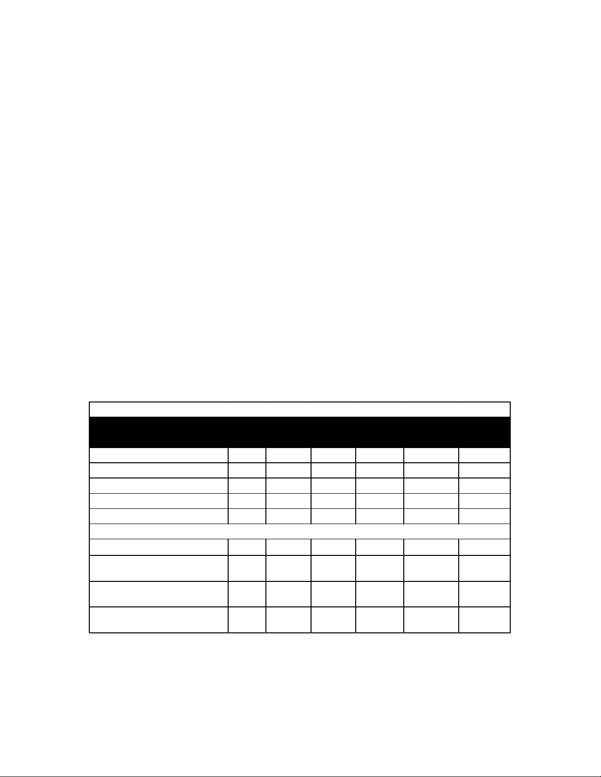
Check Daily Weekly 50 Hrs.
Every
500 hrs
Every
1500 hrs
Every
3000 hrs
Oil Level/Quality X
Oil Leaks X
Water Leaks X
Belts, Puelly X
Plumbing X
Oil Change (1 quart) p/n 01153 X X
Seal Spare Parts (1 kit/pump)
(see page 9 for kit list)
X
Oil Seal Kit (1 kit/pump)
(see page 9 for kit list)
X
Valve Spare Parts (1 kit/pump)
(see page 9 for kit list)
X
Preventative Maintenance Check List & Recommended Spare Parts List
Recommended Spare Parts
10. If the ceramic plunger pipe
(16B) is damaged, remove the
plunger bolt (16C). Discard
the old plunger pipe (16B)
and copper gasket (16D), and
clean the old locktite from the
plunger bolt (16C) and plunger
base (16A). Replace the
plunger with the new one and
locktite the plunger bolt and
torque to 220 in.-lbs. (22.5
Nm).
NOTE: If there are
deposits of any kind
(i.e., lime deposits) in
the valve casing, be
certain that the weep
holes in the weep
return ring (25) and
valve casing (26) have
not been plugged.
Reassembly sequence of the P225/P226/P223/P228 Pumps
1) If oil seals (19) were removed, replace with seal lip towards crankcase. Lubricate seals before
replacing.
2) Replace seal case (20) with o-rings (21) over plungers. Generously lubricate o-rings and oil seal
before reassembly. Replace v-sleeve (23A) over plungers (16).
3) Generously lubricate v-sleeve (23). Assemble v-sleeves (22) into valve casing (#26). Assemble
weep return ring (25) and pressure ring (24) over plungers (16). Slide valve casing over plungers
and seat rmly. Replace the eight socket head cap screws (34) and tighten to 106 in.-lbs. (12 Nm)
in a crossing pattern.
4) Replace the six o-rings (31) and the six valve assemblies (32X). Now replace the six valve plug orings (33). Apply one drop of Loctite 243 to the valve plugs (32) and tighten to 55 ft.-lbs. (75 Nm).
NOTE: Contact Giant Industries for Service School Information. Phone: (419)-531-4600
7

P225/P226/P223/P228 DIMENSIONS - Inches (mm)
GIANT INDUSTRIES LIMITED WARRANTY
Giant Industries, Inc. pumps and accessories are warranted by the manufacturer to be free from
defects in workmanship and material as follows:
1. For portable pressure washers and self-serve car wash applications, the discharge
manifolds will never fail, period. If they ever fail, we will replace them free of charge.
Our other pump parts, used in portable pressure washers and in car wash applica-
tions, are warranted for ve years from the date of shipment for all pumps used in
NON-SALINE, clean water applications.
2. One (1) year from the date of shipment for all other Giant industrial and consumer
pumps.
3. Six (6) months from the date of shipment for all rebuilt pumps.
4. Ninety (90) days from the date of shipment for all Giant accessories.
This warranty is limited to repair or replacement of pumps and accessories of which the manufacturer’s evaluation shows were defective at the time of shipment by the manufacturer. The following
items are NOT covered or will void the warranty:
1. Defects caused by negligence or fault of the buyer or third party.
2. Normal wear and tear to standard wear parts.
3. Use of repair parts other than those manufactured or authorized by Giant.
4. Improper use of the product as a component part.
5. Changes or modications made by the customer or third party.
6. The operation of pumps and or accessories exceeding the specications set forth
in the Operations Manuals provided by Giant Industries, Inc.
Liability under this warranty is on all non-wear parts and limited to the replacement or repair of those
products returned freight prepaid to Giant Industries which are deemed to be defective due to work-
manship or failure of material. A Returned Goods Authorization (R.G.A.) number and completed
warranty evaluation form is required prior to the return to Giant Industries of all products under war-
ranty consideration. Call (419)-531-4600 or fax (419)-531-6836 to obtain an R.G.A. number.
Repair or replacement of defective products as provided is the sole and exclusive remedy provided
hereunder and the MANUFACTURER SHALL NOT BE LIABLE FOR FURTHER LOSS, DAMAGES,
OR EXPENSES, INCLUDING INCIDENTAL AND CONSEQUENTIAL DAMAGES DIRECTLY OR
INDIRECTLY ARISING FROM THE SALE OR USE OF THIS PRODUCT.
THE LIMITED WARRANTY SET FORTH HEREIN IS IN LIEU OF ALL OTHER WARRANTIES OR
REPRESENTATION, EXPRESS OR IMPLIED, INCLUDING WITHOUT LIMITATION ANY WARRANTIES OR MERCHANTABILITY OR FITNESS FOR A PARTICULAR PURPOSE AND ALL SUCH
WARRANTIES ARE HEREBY DISCLAIMED AND EXCLUDED BY THE MANUFACTURER.
GIANT INDUSTRIES, INC., 900 N. Westwood Ave., Toledo, Ohio 43607
PHONE (419) 531-4600, FAX (419) 531-6836, www.giantpumps.com
Copyright 2018 Giant Industries, Inc.
12/18 P200-16mm.indd
 Loading...