

Page 1

Models
Operating Instructions /
GP5132, GP5132-SSP,
GP5136, GP5142 & GP5145
Triplex Ceramic
Plunger Pump
Manual
Updated 05/18
Contents:
Installation Instructions: page 2
Pump Specications: page 3
Exploded View: page 4
Parts List: page 5
Kits/Torque Specs: page 6
Repair Instructions: page 7
Dimensions: back page
Warranty Information back page
Page 2

INSTALLATION INSTRUCTIONS
Figures for speed (rpm) and pressure apply to
interval operation with cold water.
For continual operation, the speed of all pump
models must be limited to 700 rpm and the
max. operating pressure reduced by 10%.
Required NPSH refers to water: Specic weight
1kg/dm3, viscosity 1°E at max. permissible revolutions.
Operation and Maintenance
Check oil level prior to starting and ensure trouble-free water supply. Oil: Use only 1.2 gallons
(4.6 liters) of Industrial Gear Lube Oil (Giant p/n
01154) or ISO VG 220 (e.g. Aral Degol BG220)
or SAE 90 gear oil.
Initial change after 50 operating hours and then
every 500 operating hours.
Caution when operating in damp places or
with high temperature uctuations. Oil must
be changed immediately, should condensate
(frothy oil) occur in the gear box.
Keep NPSH under control.
Max. input pressure 145 PSI (10 bar), max. suc-
tion head -4.35 PSI (-0.3 bar).
Safety Rules
Pump operation without safety valve as well
as any excess in temperature or speed limits
automatically voids the warranty. The safety
valve must be regulated in accordance with
the guidelines for liquid spraying units so that
the admissible operating pressure can not be
exceeded by more than 10%.
When the pump is in operation, the open shaft
end must be covered up by a shaft protector
(21), the driven shaft side and coupling by a
contact-protector.
Pressure in discharge line and in pump must
be at zero before any maintenance to the pump
takes place. Close up suction line. Disconnect
fuses to ensure that the driving motor does not
get switched on accidently.
Make sure that all parts on the pressure side of
the unit are vented and relled, with pressure at
zero, before starting the pump.
In order to prevent air, or an air/water-mixture
being absorbed and to prevent cavitation occuring, te pump-npshr, positive suction head and
water temperature must be kept under control.
Cavitation and/or compression of gases lead
to uncontrollable pressure-kicks which can
ruin pump and unit parts and also be dangerous to the operator or anyone standing
nearby.
Giant plunger pumps are suitable for pumping clean water and other non-agressive or
abrasive media with a specic weight similar to
water.
Before pumping other liquids - especially
inammable, explosive and toxic media - the
pump manufacturer must under all circumstances be consulted with regard to the
resistance of the pump material. It is the responsibility of the equipment manufacturer
and/or operator to ensure that all pertinent
safety regulations are adhered to.
2
Page 3

GP5100 SERIES PUMP SPECIFICATIONS
Max.
Flow
Max.
Pressure
Max.
Speed
Power
Req’d.
Max.
Temp.
Plunger
Diameter
NPSH
Required
Model GPM PSI RPM HP F in Ft-Head
GP5132 27.7 2900 1000 57 140 1.26 27.9
GP5132* 40 3000 1444 83 140 1.26 27.9
GP5136 33.8 2320 910 56 140 1.42 27.9
GP5142 40.4 1885 800 54.4 140 1.65 N/A
GP5145 43.5 1450 750 45 140 1.77 29.5
* Intermittent rating
Max.
Flow
Max.
Pressure
Max.
Speed
Power
Req’d.
Max.
Temp.
Plunger
Diameter
NPSH
Required
Model L/min Bar RPM kW C mm mWs
GP5132 104.9 200 1000 42.8 60 32 8.5
GP5132* 151.4 207 1444 61.9 60 32 8.5
GP5136 127.8 160 910 41.8 60 36 8.5
GP5142 153.0 130 800 40.6 60 42 N/A
GP5145 164.6 100 750 33.6 60 45 9.0
* Intermittent duty only.
Horsepower Ratings:
We recommend a 1.15 service factor be specied when selecting an electric motor as the power source.
To compute electric motor horsepower required, use the following formula: HP = (GPM X PSI) / 1450.
The formula to determine the horsepower required for a gas engine is: HP = (GPM X PSI) / 1150.
The formula to determine the horsepower required for a diesel engine is: HP = (GPM X PSI) / 1250.
For the Application of a Hydraulic Motor:
To Determine the Torque of a Hydraulic Motor -- (GPM x PSI x 36.77) / RPM = Torque (in-lbs)
Calculating RPM / GPM of Pump:
A pump must be connected to an electric motor or gas or diesel engine with the correct ratio of pulleys
and belts to attain the required speed and GPM. The use of a Variable Frequency Drive (VFD) may also
be used to control the RPM of a properly sized electric motor when variable ows are required.
(Max. Pump RPM / Rated Pump GPM) x Required Pump GPM = Required Pump RPM
To calculate a pulley diameter one (1) pulley diameter and the required pump RPM must be known:
(Pump RPM x Pump Pulley Diameter) / Motor RPM = Motor Pulley Diameter
(Motor RPM x Motor Pulley Diameter) / Pump RPM = Pump Pulley Diameter
Common Specications:
Inlet Pressure ..-4.35 to 145 PSI (-0.3 to 10 Bar)
Max. Temperature ..................140 oF (60 oC)
Crankshaft Diameter..............1.38” (35mm)
Crankcase Oil Capacity .........1.2 Gal. (4.6 L)
Inlet Ports ..............................(2) 1-1/2” NPT
Discharge Ports .....................(2) 1” NPT
Stroke ....................................1.81” (46mm)
Weight ...................................179 lbs (81kg)
Shaft Rotation ..Top of Pulley Toward Fluid End
Materials Used for MP Pumps:
Manifold ........ Nickel-Plated Spheroidal Cast Iron
Plungers ....... Solid Ceramic Oxide
Valves ........... Duplex Steel/Plastic Retainer
Seals............. Nitrile with Fabric Reinforcing
Gear End ...... Spheroidal Cast Iron
Consult the factory for special requirements that
must be met if the pump is to operate beyond
one or more of the limits specied above.
3
Page 4
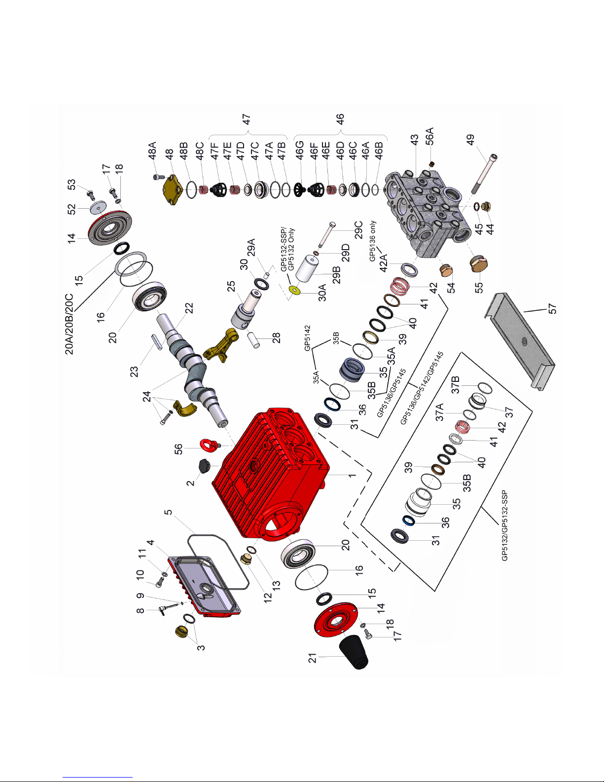
EXPLODED VIEW - GP5132, GP5132-SSP, GP5136, GP5142 & GP5145 PUMPS
4
Page 5

GP5132, GP5132-SSP, GP5136, GP5142 & GP5145 SPARE PARTS LIST
ITEM PART DESCRIPTION QTY.
1 13266 Crankcase 1
2 13000 Oil Filler Plug Assembly 1
3 05943 Oil Sight Glass Assy. 1
4 13267 Crankcase Cover 1
5 13268 O-Ring 1
8 07105 Oil Dip Stick 1
9 01009 O-Ring, Dip Stick 1
10 07008 Inner Hexagon Screw 4
11 06725 Spring Washer 4
12 07703 Drain Plug, 3/4” BSP 1
13 07704 Gasket, Drain Plug 1
14 13271 Bearing Cover 2
15 13272 Radial Shaft Seal 2
16 08182 O-Ring 2
17 13358 Hexagon Screw 8
18 06725 Spring Washer 8
20 13206 Taper Roller Bearing 2
20A 13207 Shim, 0.1mm 1-5
20B 04723 Shim, 0.15mm 1-5
20C 04724 Shim, 0.2mm 1-5
21 13273 Shaft Protector 1
22 13274 Crankshaft 1
23 13275 Fitting Key 1
24 13276 Connecting Rod Assy. 3
25 13279 Crosshead Assy. 3
28 13281 Crosshead Pin 3
29A 07125 Centering Sleeve 3
29B 13022 Plunger Pipe (GP5132) 3
29B 13022-SS Plunger Pipe (GP5132-SSP) 3
29B 07130 Plunger Pipe (GP5136) 3
29B 07736 Plunger Pipe (GP5142) 3
29B 13283 Plunger Pipe (GP5145) 3
29C 13031 Tensioning Screw 3
29D 07755 Copper Ring 3
30 13282 Oil Scraper 3
30A 05889 Washer for Drip Shield
(GP5132/-SSP Only) 3
31 13284 Radial Shaft Seal 3
35 13359 Seal Sleeve (GP5132/-SSP) 3
35 13288 Seal Sleeve (GP5136) 3
35 04325 Seal Sleeve (GP5142) 3
35 13287 Seal Sleeve (GP5145) 3
35A 13289 O-Ring (GP5136) 3
35A 08183 O-Ring (GP5142)
35A 13286 O-Ring (GP5145) 3
35B 08183 O-Ring (except GP5142) 3
35B 13286 O-Ring (GP5142 only)
36 13360 Grooved Ring
(GP5132/-SSP) 3
36 13291 Grooved Ring (GP5136) 3
36 04323 Grooved Ring (GP5142) 3
36 13290 Grooved Ring (GP5145) 3
37 13361 Seal Case (GP5132/-SSP) 3
37A 07700 O-Ring (GP5132/-SSP) 3
37B 07653 O-Ring (GP5132/-SSP) 3
ITEM PART DESCRIPTION QTY.
39 13026 Pressure Ring
(GP5132/-SSP) 3
39 07142 Pressure Ring (GP5136) 3
39 07744 Pressure Ring (GP5142) 3
39 13293 Pressure Ring (GP5145) 3
40 13027 V-Sleeve (GP5132/-SSP) 6
40 07144 V-Sleeve (GP5136) 6
40 07745 V-Sleeve (GP5142) 6
40 13294 V-Sleeve (GP5145) 6
41 13028 Sleeve Support Ring
(GP5132/-SSP) 3
41 07146 Sleeve Support Ring
(GP5136) 3
41 07746 Sleeve Support Ring
(GP5142) 3
41 13296 Sleeve Support Ring
(GP5145) 3
42 07173 Tension Spring
(GP5132/-SSP) 3
42 07147 Tension Spring (GP5136) 3
42 13297 Tension Spring (GP5142) 3
42 13297 Tension Spring (GP5145) 3
42A 13298 Spring Guide
(GP5136 only) 3
43 13300 Valve Casing 1
44 07109 Plug, 1/2” BSP 1
45 06272 Copper Washer, 1/2” BSP 1
46 13302 Suction Valve Assy. 3
46A 12055 O-Ring 3
46B 08059 O-Ring 3
46C 13304 Suction Valve Seat 3
46D 13306 Valve Plate 3
46E 13307 Valve Spring 3
46F 13308 Spring Tension Cap 3
46G 13309 Spacer Pipe 3
47 13311 Discharge Valve Assy. 3
47A 13289 O-Ring 3
47B 07700 O-Ring 3
47C 13314 Discharge Valve Seat 3
47D 13306 Valve Plate 3
47E 13307 Valve Spring 3
47F 13308 Spring Tension Cap 3
48 13316 Plug 3
48A 07008 Inner Hexagon Screw 12
48B 07740 O-Ring 3
48C 07232 Pressure Spring 3
49 13339 Inner Hexagon Screw 8
52 13362 Disc for Crankshaft 1
53 13358 Hexagon Screw 1
54 06626 Plug, 1” NPT 1
55 06627 Plug, 1-1/2” NPT 2
56 07623 Eye Bolt 1
56A 22610 Plug, 1/4” NPT 3
57 04334 Drip Tray 1
5
Page 6

GP5132, GP5132-SSP, GP5136, GP5142 and GP5145 REPAIR KITS
Plunger Packing Kits
GP5132/GP5132-SSP #09290
Item Part# Description Qty.
35B 08183 O-Ring 3
36 13360 Grooved Ring 3
37A 07700 O-Ring 3
37B 07653 O-Ring 3
40 13027 V-Sleeve 6
GP5136 #09229
Item Part# Description Qty.
35A 13289 O-Ring 3
35B 08183 O-Ring 3
36 13291 Grooved Ring 3
40 07144 V-Sleeve 6
GP5142 #09767
Item Part# Description Qty.
35A 08183 O-Ring 3
35B 13286 O-Ring 3
36 04323 Grooved Ring 3
40 07745 V-Sleeve 6
GP5145 #09228
Item Part# Description Qty.
35A 13286 O-Ring 3
35B 08183 O-Ring 3
36 13290 Grooved Ring 3
40 13294 V-Sleeve 6
Oil Seal Kit
GP5100 Series, #09230
Item Part # Description Qty.
31 13284 Oil Seal 3
Valve Assembly Kits
Inlet Valve Kit, GP5100 Series, #09231
Item Part # Description Qty.
46A 12055 O-Ring 1
46B 08059 O-Ring 1
46C 13304 Valve Seat 1
46D 13306 Valve Plate 1
46E 13307 Valve Spring 1
Discharge Valve Kit, GP5100 Series, # 09232
Item Part # Description Qty.
47A 13289 O-Ring 1
47B 07700 O-Ring 1
47C 13314 Valve Seat 1
47D 13306 Valve Plate 1
47E 13307 Valve Spring 1
Complete Valve Repair Kit, #09812
Item Part # Description Qty.
46A 12055 O-Ring 3
46B 08059 O-Ring 3
46C 13304 Inlet Valve Seat 3
46D 13306 Valve Plate 3
46E 13307 Valve Spring 3
46F 13308 Spring Tension Cap 3
46G 13309 Spacer Pipe 3
47A 13289 O-Ring 3
47B 07700 O-Ring 3
47C 13314 Discharge Valve Seat 3
47D 13306 Valve Plate 3
47E 13307 Valve Spring 3
47F 13308 Spring Tension Cap 3
48B 07740 O-Ring 3
GP5132, GP5132-SSP, GP5136 GP5142 & GP5145 Series
Torque Specications and Lubrication Information
Position Item# Description Lubrication/Loctite Torque Amount
1 13266 Crankcase Molycote Cu-Paste
3 05943 Oil Sight Glass Assembly Loctite 572 22 ft.-lbs. (30 Nm)
10 07008 Inner Hexagon Screw 33 ft.-lbs. (45 Nm)
12 07703 Drain Plug, 3/4” BSP 74 ft.-lbs. (100 Nm)
17 13358 Hexagon Screw 33 ft.-lbs. (45 Nm)
24 13276 Connecting Rod Assy. 22 ft.-lbs. (30 Nm)
29C 13031 Tension Screw, Plunger Loctite 243 22 ft.-lbs. (30 Nm)
31 13284 Radial Shaft Seal Loctite 403
48A 07008 Inner Hexagon Screw, Plug Pro Pack 550 35 ft.-lbs. (47 Nm)
49 13339 Inner Hexagon Screw, Valve Casing 89 ft.-lbs. (120 Nm)
6
Page 7

GP5132, GP5132-SSP, GP5136, GP5142 and GP5145 REPAIR INSTRUCTIONS
To Check Valves
Remove inner hexagon screw (48A) and remove plugs (48) with a screwdriver. Check O-rings on plugs (48).
Pull out tension spring (48C). Remove the spring tension disc (47F) from discharge valve lying underneath by
screwing in the M10-screw. Take out spring (47E) and plate (47D). Pull out valve seat (47C) by means of an
valve puller. Check sealing areas of plate and valve seat for damage and replace worn parts. Check O-rings
(47A) and (47B). Screw spacer pipe (46G) out of spring tension cap (46F) in the suction valve lying underneath.
Remove suction valve by screwing in an M10-screw. Check O-ring (46A) and (46B). If valve seat (46C) remains
in the valve casing (43) then carry forth as described for discharge valve. When reassembling, use new O-rings
if possible and oil them before installing.
Tighten inner hexagon screws (48A) to 35 ft.-lbs. (47 Nm).
To Check Seals and Plunger Pipe
Loosen the inner hexagon screws (49) and pull off valve casing (43) to the front. Pull seal sleeves (35) out of
guides in crankcase and over the plunger pipe (29B). Pull support ring (41), sleeves (40) and pressure ring (39)
out of seal sleeve.
Check plunger surfaces, sleeves (40) and grooved rings (36). Replace worn parts.
If the plunger pipe is worn out, loosen tension screw (29C) and pull off plunger pipe to the front. Clean contact
surfaces of plunger (25) thoroughly. Then place new plunger pipe carefully through the oiled seals into the seal
case. Check o-rings on seal sleeves and seal case (GP5132/GP5132-SSP only) and replace worn o-rings. Then
push seal sleeve together with plunger pipe into the crankcase guide. Turn gear carefully until plunger (25) comes
up against the plunger pipe. Put a new copper gasket (29D) onto the tension screw (29C). Cover the thread of
tension screw and the gasket with glue and tighten to 29 ft.-lbs. (30 Nm).
Important! Care must be taken that no glue gets between the plunger pipe (29B) and the centering sleeve
(29A). The plunger pipe should not be strained by eccentric tightening of the tension screw or through damage
to front of surface of plunger, otherwise it will probably break. Tighten the inner screws (49) for the valve casing
evenly to 89 ft.-lbs. (120 Nm).
To Dismantle Gear
Drain oil after dismantling valve case and plunger pipes and screw off crankcase cover (4) and bearing cover
(14).
Loosen con rod screws (24), push stem of con rod as far as possible into the crosshead guide and carefully
push out the radial shaft seals (31).
Important! Connecting rods are marked for identication. Do not twist con rod halves. Con rod is to be reinstalled
in the same position on shaft journals.
While slightly turning the crankshaft, hit it out carefully to one side with a rubber hammer.
Important! Do not bend con rod shank. Finally, check surfaces of shaft, con rod, crosshead and plungers (25)
as well as radial shaft seals (15, 31) and taper roller bearings (20).
To Reassemble
Using a soft tool, press in the outer bearing ring until it lines up with the outer edge of the bearing hole. Remove
bearing cover together with shaft ring and O-ring. Fit shaft with pressed-on bearing parts through the bearing
hole on the opposite side. Press in outer bearing ring and tension it inwards with the bearing cover, keeping the
shaft in vertical position and turning it slowly so that the taper rollers of the bearings touch the edge of the outer
bearing ring. Adjust axial bearing clearance with tting discs 0.1mm (20A). Shaft should turn easily with very
little clearance. Tighten inner hexagon screws on con rod (24) to 22 ft.-lbs. (30 Nm).
Important! There should be enough clearance for the con rod to move sideways a little on the journals.
Important! The 1/2” BSP connection in the crankcase serves the purpose of
draining leakage water. The connection should not be closed (see the drawing
to the right).
7
Page 8

dimensions
10mm X 63mm Key
outlet
2 x 1” nPt
18.9”
4.61” 13.9”
3.06”
2.68”
9.06”
2.87”
8.27”
10.2”
9.69”
4.33”
2.17”
7.68”
20.6”
inlet
3 x 1-1/2” nPt
19.1”
GIANT INDUSTRIES LIMITED WARRANTY
Giant Industries, Inc. pumps and accessories are warranted by the manufacturer to be free from
defects in workmanship and material as follows:
1.For portable pressure washers and car wash applications, the discharge manifolds will never fail,
period. If they ever fail, we will replace them free of charge. Our other pump parts, used in portable
pressure washers and in car wash applications, are warranted for ve years from the date of shipment
for all pumps used in NON-SALINE, clean water applications.
2. One (1) year from the date of shipment for all other Giant industrial and consumer pumps.
3. Six (6) months from the date of shipment for all rebuilt pumps.
4. Ninety (90) days from the date of shipment for all Giant accessories.
This warranty is limited to repair or replacement of pumps and accessories of which the manufacturer’s evaluation shows were defective at the time of shipment by the manufacturer. The following
items are NOT covered or will void the warranty:
1. Defects caused by negligence or fault of the buyer or third party.
2. Normal wear and tear to standard wear parts.
3. Use of repair parts other than those manufactured or authorized by Giant.
4. Improper use of the product as a component part.
5. Changes or modications made by the customer or third party.
6. The operation of pumps and or accessories exceeding the specications set forth
in the Operations Manuals provided by Giant Industries, Inc.
Liability under this warranty is on all non-wear parts and limited to the replacement or repair of
those products returned freight prepaid to Giant Industries which are deemed to be defective due to
workmanship or failure of material. A Returned Goods Authorization (R.G.A.) number and completed
warranty evaluation form is required prior to the return to Giant Industries of all products under warranty
consideration. Call (419)-531-4600 or fax (419)-531-6836 to obtain an R.G.A. number.
Repair or replacement of defective products as provided is the sole and exclusive remedy provided
hereunder and the MANUFACTURER SHALL NOT BE LIABLE FOR FURTHER LOSS, DAMAGES,
OR EXPENSES, INCLUDING INCIDENTAL AND CONSEQUENTIAL DAMAGES DIRECTLY OR INDIRECTLY ARISING FROM THE SALE OR USE OF THIS PRODUCT.
THE LIMITED WARRANTY SET FORTH HEREIN IS IN LIEU OF ALL OTHER WARRANTIES OR
REPRESENTATION, EXPRESS OR IMPLIED, INCLUDING WITHOUT LIMITATION ANY WARRANTIES
OR MERCHANTABILITY OR FITNESS FOR A PARTICULAR PURPOSE AND ALL SUCH WARRANTIES ARE HEREBY DISCLAIMED AND EXCLUDED BY THE MANUFACTURER.
GIANT INDUSTRIES, INC., 900 N. Westwood Ave., Toledo, Ohio 43607
Phone (419) 531-4600, FAX (419) 531-6836, www.giantpumps.com
© Copyright 2018 Giant Industries, Inc.
05/18 GP5132_GP5136_GP5145.indd
 Loading...