

Page 1

Triplex Ceramic
Plunger Pump
Operating Instructions /
Models
GP5120, GP5122 & GP5124
Manual
updated 01/17
Contents:
Installation Instructions: page 2
Pump Specications: page 3
Exploded View: page 4
Parts List: page 5
Kits/Torque Specs: page 6
Repair Instructions: page 7
Dimensions: back page
Warranty Information back page
Page 2

INSTALLATION INSTRUCTIONS
Operation and Maintenance
Check oil level prior to starting and ensure
trouble-free water supply.
Important! If there is a danger of frost, the water in the pump and in the pump ttings (particularly the unloader valve) must be emptied. The
second discharge port can also be used and the
pump run “dry” for 1-2 minutes for this purpose.
Oil: Use only 1.2 gal. (4.6 L) SAE 80W-90 Industrial Gear Lube Oil.
Before putting the pump into operation for
the rst time, and every time the suction line
is emptied, the plugs (37) must be removed
and the pump cranked manually or started
briey until water emerges out of the plug
bores. This procedure serves to vent the
drip-return so that the low-pressure seals
(32) do not run dry.
Thereafter the plugs (34) must be screwed back
on and tightened.
Initial oil changed after 50 operating hourse and
then every 1000 operating hours, or after 1 year
if used less.
Caution when operating in damp places or with
high temperature uctuations. Oil must be
changed immediately should condensate (frothy
oil) occur in the gear box.
NPSH values must be respected.
Max. input pressure 145 PSI (10 bar), max.
suction head -4.35 PSI (-0.3) bar. Make sure
that suction pulsation is sufciently dampened -
water column resonance must be avoided.
Safety Rules
A safety valve is to be installed in accordance
with the guidelines for liquid spraying units so
that the admissible operating pressure cannot
be exceeded by more than 10%.
Pump operation without a safety valve as well
as any excess in temperature or speed limits
automatically voids the warranty.
When the pump is in operation, the shaft end
must be covered by shaft protector (21) and the
driven shaft side and coupling by a protective
cover.
Pressure in the discharge line and in the pump
must be at zero before any maintenance to the
pump takes place. Close off suction line.
Take necessary precautions to ensure that the
driving motor cannot get switched on accidently
(by disconnecting the fuses, for example).
Make sure that the pump and all parts on the
pressure side of the unit are vented and relled,
with pressure at zero, before starting the pump.
In order to prevent air, or an air/water mixture
being absorbed and to prevent cavitation oc-
curring, the pump positive suction head (npshr)
and water temperature must be respected.
Cavitation and/or compression of gases lead
to uncontrollable pressure spikes which can
ruin pump and unit parts and also be dan-
gerous to the operator and anyone standing
nearby.
Giant plunger pumps are suitable for pump-
ing clean water and other non-aggressive or
abrasive media with a specic weight similar to water. Before pumping other liquids
- especially ammable, explosive and toxic
media - Giant must be consulted with regard
to the resistance of the pump material. It is
the reposnsibility of the equimpment manufacturer and/or operator to ensure that all
pertinent safety regualtions are adhered to.
2
Page 3

GP5120/GP5122/GP5124 SERIES PUMP SPECIFICATIONS
Max.
Flow
Max.
Pressure
Max.
Speed
Power
Req’d.
Max.
Temp.
Plunger
Diameter
NPSH
Required
Model GPM PSI RPM HP °F in Ft-Head
GP5120 10.5 8700 1000 63.3 140 0.787 27.9
GP5122 11.9 7250 930 59.0 140 0.866 27.9
GP5124 13.2 5800 850 53.8 140 0.945 27.9
Max.
Flow
Max.
Pressure
Max.
Speed
Power
Req’d.
Max.
Temp.
Plunger
Diameter
NPSH
Required
Model L/min Bar RPM kW °C mm mWs
GP5120 40.0 600 1000 47.2 60 20 8.5
GP5122 45.0 500 930 44.0 60 22 8.5
GP5124 50.0 400 850 40.1 60 24 8.5
Horsepower Ratings:
We recommend a 1.15 service factor be specied when selecting an electric motor as the power source.
To compute electric motor horsepower required, use the following formula: HP = (GPM X PSI) / 1450.
The formula to determine the horsepower required for a gas engine is: HP = (GPM X PSI) / 1150.
The formula to determine the horsepower required for a diesel engine is: HP = (GPM X PSI) / 1250.
For the Application of a Hydraulic Motor:
To Determine the Torque of a Hydraulic Motor -- (GPM x PSI x 36.77) / RPM = Torque (in-lbs)
Calculating RPM / GPM of Pump:
A pump must be connected to an electric motor or gas or diesel engine with the correct ratio of pulleys
and belts to attain the required speed and GPM. The use of a Variable Frequency Drive (VFD) may also
be used to control the RPM of a properly sized electric motor when variable ows are required.
(Max. Pump RPM / Rated Pump GPM) x Required Pump GPM = Required Pump RPM
To calculate a pulley diameter one (1) pulley diameter and the required pump RPM must be known:
(Pump RPM x Pump Pulley Diameter) / Motor RPM = Motor Pulley Diameter
(Motor RPM x Motor Pulley Diameter) / Pump RPM = Pump Pulley Diameter
Common Specications:
Inlet Pressure ..-4.35 to 145 PSI (-0.3 to 10 Bar)
Max. Temperature ..................140 oF (60 oC)
Crankshaft Diameter..............1.38” (35mm)
Crankcase Oil Capacity .........1.2 Gal. (4.6 L)
Inlet Ports ..............................(2) 3/4” BSP
Discharge Ports .....................(2) 1/2” BSP
Stroke ....................................1.81” (46mm)
Weight ...................................176 lbs (80 kg)
Shaft Rotation ..Top of Pulley Toward Fluid End
Materials Used for MP Pumps:
Manifold ........AISI 303 Stainless Steel
Plungers .......Solid Ceramic
Valves ........... Duplex Steel
Seals............. Aramide/Teon Packing
Gear End ...... Spheroidal Cast Iron
Crankshaft .... Drop-forged and case-hardened
Consult the factory for special requirements that
must be met if the pump is to operate beyond
one or more of the limits specied above.
3
Page 4
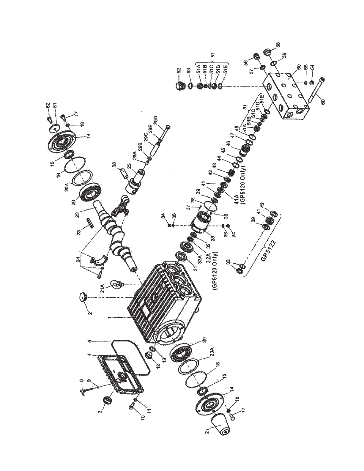
EXPLODED VIEW - GP5120, GP5122 & GP5124 PUMPS
4
Page 5

GP5120, GP5122 & GP5124 SPARE PARTS LIST
ITEM PART DESCRIPTION QTY.
1 13266 Crankcase 1
2 13000 Oil Filler Plug Assembly 1
3 05943 Oil Sight Glass Assy. 1
4 13267 Crankcase Cover 1
5 13268 O-Ring 1
8 07105 Oil Dip Stick 1
9 01009 O-Ring, Dip Stick 1
10 07008 Inner Hexagon Screw 4
11 06725 Spring Washer 4
12 07703 Drain Plug G 3/4” 1
13 07704 Gasket, Drain Plug 1
14 13271 Bearing Cover 2
15 13272 Radial Shaft Seal 2
16 08182 O-Ring 2
17 13358 Hexagon Screw 8
18 06725 Spring Washer 8
20 13206 Taper Roller Bearing 2
20A 13207 Fitting Disc (Shim) 1-5
21 13273 Shaft Protector 1
21A 07623 Eye Bolt 1
22 13274 Crankshaft 1
23 13275 Fitting Key 1
24 13276 Connecting Rod Assy. 3
25 13279 Crosshead Assy. 3
28 13281 Crosshead Pin 3
29A 07125 Centering Sleeve 3
29B 04489 Pluger Extension (GP5120) 3
29B 04500 Pluger Extension (GP5122) 3
29B 04506 Pluger Extension (GP5124) 3
29C 07126 Plunger Pipe (GP5120) 3
29C 04501 Plunger Pipe (GP5122) 3
29C 07127 Plunger Pipe (GP5124) 3
29D 04507 Tensioning Screw 3
29E 07755 Copper Ring 3
31 13284 Radial Shaft Seal 3
32 13037 Grooved Ring (GP5120) 3
32 06249 Grooved Ring (GP5122) 3
32 13049 Grooved Ring (GP5124) 3
32A 08346 Support Ring (GP5120 only) 3
33 04490 Seal Sleeve (GP5120) 3
33 04509 Seal Sleeve
(GP5122 & GP5124) 3
33A 04491 Centring Ring (GP5120) 3
33A 04502 Centring Ring (GP5122) 3
33A 04508 Centring Ring (GP5124) 3
34 06589 Plug, 1/8” BSP 6
35 06709 Seal 6
ITEM PART DESCRIPTION QTY.
36 07023 O-Ring 3
37 22764 Notched Pin 3
38 07303 O-Ring 3
39 04492 Guide Ring (GP5120) 3
39 04503 Guide Ring (GP5122) 3
39 04381 Guide Ring (GP5124) 3
41 07783 Spiral Ring (GP5120) 6
41 04504 Spiral Ring (GP5122) 6
41 07685 Spiral Ring (GP5124) 6
41A 04475 Guide Ring (GP5120 only) 3
42 04476 Support Disc (GP5120) 3
42 04505 Support Disc (GP5122) 3
42 04510 Support Disc (GP5124) 3
43 07210 Pressure Spring (GP5120) 3
43 07338 Pressure Spring
(GP5122 & GP5124) 3
44 07150 O-Ring (GP5120) 3
44 12055 O-Ring
(GP5122 & GP5124) 3
45 04493 Support Ring (GP5120) 3
45 07693 Support Ring
(GP5122 & GP5124) 3
46 04477 Seal Case (GP5120) 3
46 04511 Seal Case
(GP5122 & GP5124) 3
47 06266 Support Ring 3
48 07150 O-Ring 3
50 04494 Valve Casing
(GP5120 & GP5122) 1
50 04512 Valve Casing (GP5124) 1
51 04513 Valve Assembly 6
51A 06939 Spring Tension Cap 6
51B 06377 Valve Spring 6
51C 06938 Valve Plate 6
51D 06937 Valve Seat 6
51E 04123 O-Ring 6
52 05971 Plug, M33 x 1.5 3
53 05972 O-Ring 3
54 07423 Plug, 1/4” BSP 3
55 07161 Copper Ring, 1/4” 3
56 13434 Plug, 1/2” BSP 1
57 06272 Copper Seal Ring 1
58 07703 Plug, 3/4” BSP 1
59 07704 Copper Seal Ring 1
60 13339 Inner Hexagon Screw 8
61 13362 Disc for Crankshaft 1
62 13358 Hexagon Screw 1
5
Page 6

GP5120, GP5122 and GP5124 REPAIR KITS
Plunger Packing Kits
GP5120 - #09784
Item Part# Description Qty.
36 07023 O-Ring 3
38 07303 O-Ring 3
39 04492 Grooved Ring 3
41 07783 Spiral Ring 6
41A 04475 Guide Ring 3
44 07150 O-Ring 3
45 04493 Support Ring 3
47 06266 Support Ring 3
48 07150 O-Ring 3
GP5122 - #09785
Item Part# Description Qty.
36 07023 O-Ring 3
38 07303 O-Ring 3
39 04503 Guide Ring 3
41 04504 Spiral Ring 6
44 12055 O-Ring 3
45 07693 Support Ring 3
47 06266 Support Ring 3
48 07150 O-Ring 3
Valve Assembly and Oil Seal Kits
Valve Assembly Kit - #09787
Item Part # Description Qty.
47 06266 Support Ring 3
48 07150 O-Ring 3
51 04513 Valve Assembly 6
53 05972 O-Ring 3
Oil Seal Kits
GP5120 - #09783
Item Part # Description Qty.
32 13037 Grooved Ring 3
32A 08346 Support Ring 3
GP5122 & GP5124 - #09230
Item Part # Description Qty.
31 13284 Oil Seal 3
GP5124 - #09786
Item Part# Description Qty.
36 07023 O-Ring 3
38 07303 O-Ring 3
39 04381 Guide Ring 3
40 07718 Support Ring 3
41 07685 Spiral Ring 6
44 12055 O-Ring 3
45 07693 Support Ring 3
47 06266 Support Ring 3
48 07150 O-Ring 3
GP5120, GP5122 & GP5124 Torque Specications
Position Item# Description Torque Amount - Ft.-lbs (NM)
24 13276 Connecting Rod Assy. 22 (30)
29D 04507 Tension Screw, Plunger 26 (35)
52 05971 Plug 107 (145)
60 13339 Inner Hexagon Screw, Valve Casing 74-89 (100-120)
6
Page 7

GP5120, GP5122 and GP5124 REPAIR INSTRUCTIONS
To Check Valves
Discharge Valves: remove valve plugs (52) using allen wrench. Using a screwdriver, carefully push the exposed
spring tension cap (51A) to the side to remove it from the valve seat (51D). Take out the spring tension cap,
valve spring (51B) and valve plate (51C). Pull out valve seat (51D) using an extractor tool (ø12-ø16 mm).
To dismantle the complete valve, place a screwdriver through a gap in the spring tension cap, press on the valve
plate and lever the valve apart. Tighten plugs (52) at 107 ft.-lbs. (145 Nm).
Suction Valves: remove hexagon socket screws (60) and pull valve casing (50) past the plungers (29A-29E) and
to the front. Continue as described above under Discharge Valves.
Examine valves and replace worn parts.
To Check Seals and Plunger Pipe
Unscrew the 8 hexagon socket screws (60) and pull the valve casing (50) off to the front. Pull seal sleeves (33)
out of the guides in the crankcase. Remove seal case (46) from the seal sleeve (33) where necessary. Take
tension spring (43) and seal unit (39-42) out of the seal sleeve. Remove plugs (34). Check that the leakage
bores are free from deposits of all kinds. Check plunger surfaces and seals. Replace worn seals. After removing
support disc (31), check leakage seal (32) and replace if necessary. If the plunger surface is worn remove tension
screw (29D), clean the centring hole and the front of the plunger crosshead (25). Then carefully thread a new
plunger pipe through oiled seals into the seal sleeve. Put centring sleeve (29A) together with plunger extension
(29B) onto plunger crosshead (25). Place the seal sleeves together with the plunger pipe into the drive. Put a
new copper seal ring (29E) onto tension screw (29D). Lightly coat the threads of the tension screw as well as
the seal ring with glue (Loctite) and tighten at 26 ft.-lbs. (35 Nm).
Important! Glue must never come between plunger extension (29B), plunger pipe (29C) and centring sleeve
(29A). Deformation of the plunger pipe due to excessive tightening of the tension screw or dirt or damage on
the front surface can cause the plunger pipe to fracture. The seal sleeves must be tted so that grooved pins
(37) are on top. Put tension spring (43) into seal casing (33) and place the seal case (46) into the valve casing.
Carefully centre the valve casing with the tted seal cases onto the seal sleeves and against the crankcase.
Then tighten hexagon socket screws (60) to 74-89 ft.-lbs. (100-120 Nm) to secure the valve casing.
To Dismantle Gear
Drain oil after dismantling valve casing and plunger pipes. Remove crankcase cover (4) and bearing cover (14).
Remove connecting rod screws (24), push the front connecting rod parts as far as possible into the crosshead
guide and carefully push out the radial shaft seals (31).
Important! Do not twist the connecting rod halves. The connecting rods are marked for identication and must
be remounted onto the shaft journals in their exact original position.
Turn the crankshaft lightly and hit it out to one side using a rubber hammer.
Important! Do not bend connecting rod shanks. Examine the surfaces of the crankshaft, connecting rods,
crossheads and plungers (25) as well as radial shaft seals (15, 31) and taper roller bearings (20) for wear.
To Reassemble
Using a soft tool, press in the outer bearing ring on one side until it lines up with the outer edge of the bearing
hole. Screw on the bearing cover together with shaft ring and o-ring. Fit the crankshaft with pressed-on bearing
parts through the bearing hole on the opposite side. Press in outer bearing ring and tension it inwards with the
bearing cover, keeping shaft in vertical position and turning it slowly so that the taper rollers of the bearings touch
the edge of the outer bearing ring. Adjust axial bearing clearance with shims 0.1 mm (20A). Shaft should turn
easily with very little clearance. Tighten hexagon socket screws on connecting rod (24) at 22 ft.-lbs. (30 Nm).
Important! A little clearance must exist to enable slight sideward movement of the connecting rod on its
journal.
Important! The 1/2” BSP connection in the crankcase serves the purpose of
draining leakage water. The connection should not be closed (see the drawing
to the right).
7
Page 8

d i m e n s i o n s - i n c h e s (m m )
GIANT INDUSTRIES LIMITED WARRANTY
Giant Industries, Inc. pumps and accessories are warranted by the manufacturer to be free from
defects in workmanship and material as follows:
1.For portable pressure washers and car wash applications, the discharge manifolds will never fail,
period. If they ever fail, we will replace them free of charge. Our other pump parts, used in portable
pressure washers and in car wash applications, are warranted for ve years from the date of shipment
for all pumps used in NON-SALINE, clean water applications.
2. One (1) year from the date of shipment for all other Giant industrial and consumer pumps.
3. Six (6) months from the date of shipment for all rebuilt pumps.
4. Ninety (90) days from the date of shipment for all Giant accessories.
This warranty is limited to repair or replacement of pumps and accessories of which the manu-
facturer’s evaluation shows were defective at the time of shipment by the manufacturer. The following
items are NOT covered or will void the warranty:
1. Defects caused by negligence or fault of the buyer or third party.
2. Normal wear and tear to standard wear parts.
3. Use of repair parts other than those manufactured or authorized by Giant.
4. Improper use of the product as a component part.
5. Changes or modications made by the customer or third party.
6. The operation of pumps and or accessories exceeding the specications set forth
in the Operations Manuals provided by Giant Industries, Inc.
Liability under this warranty is on all non-wear parts and limited to the replacement or repair of
those products returned freight prepaid to Giant Industries which are deemed to be defective due to
workmanship or failure of material. A Returned Goods Authorization (R.G.A.) number and completed
warranty evaluation form is required prior to the return to Giant Industries of all products under warranty
consideration. Call (419)-531-4600 or fax (419)-531-6836 to obtain an R.G.A. number.
Repair or replacement of defective products as provided is the sole and exclusive remedy provided
hereunder and the MANUFACTURER SHALL NOT BE LIABLE FOR FURTHER LOSS, DAMAGES,
OR EXPENSES, INCLUDING INCIDENTAL AND CONSEQUENTIAL DAMAGES DIRECTLY OR INDIRECTLY ARISING FROM THE SALE OR USE OF THIS PRODUCT.
THE LIMITED WARRANTY SET FORTH HEREIN IS IN LIEU OF ALL OTHER WARRANTIES OR
REPRESENTATION, EXPRESS OR IMPLIED, INCLUDING WITHOUT LIMITATION ANY WARRANTIES
OR MERCHANTABILITY OR FITNESS FOR A PARTICULAR PURPOSE AND ALL SUCH WARRANTIES ARE HEREBY DISCLAIMED AND EXCLUDED BY THE MANUFACTURER.
GIANT INDUSTRIES, INC., 900 N. Westwood Ave.,
Toledo, Ohio 43607, Phone (419) 531-4600, FAX (419) 531-6836,
www.giantpumps.com
© Copyright 2017 Giant Industries, Inc.
01/17 GP5120_GP5122_GP5124.indd
 Loading...