

Page 1
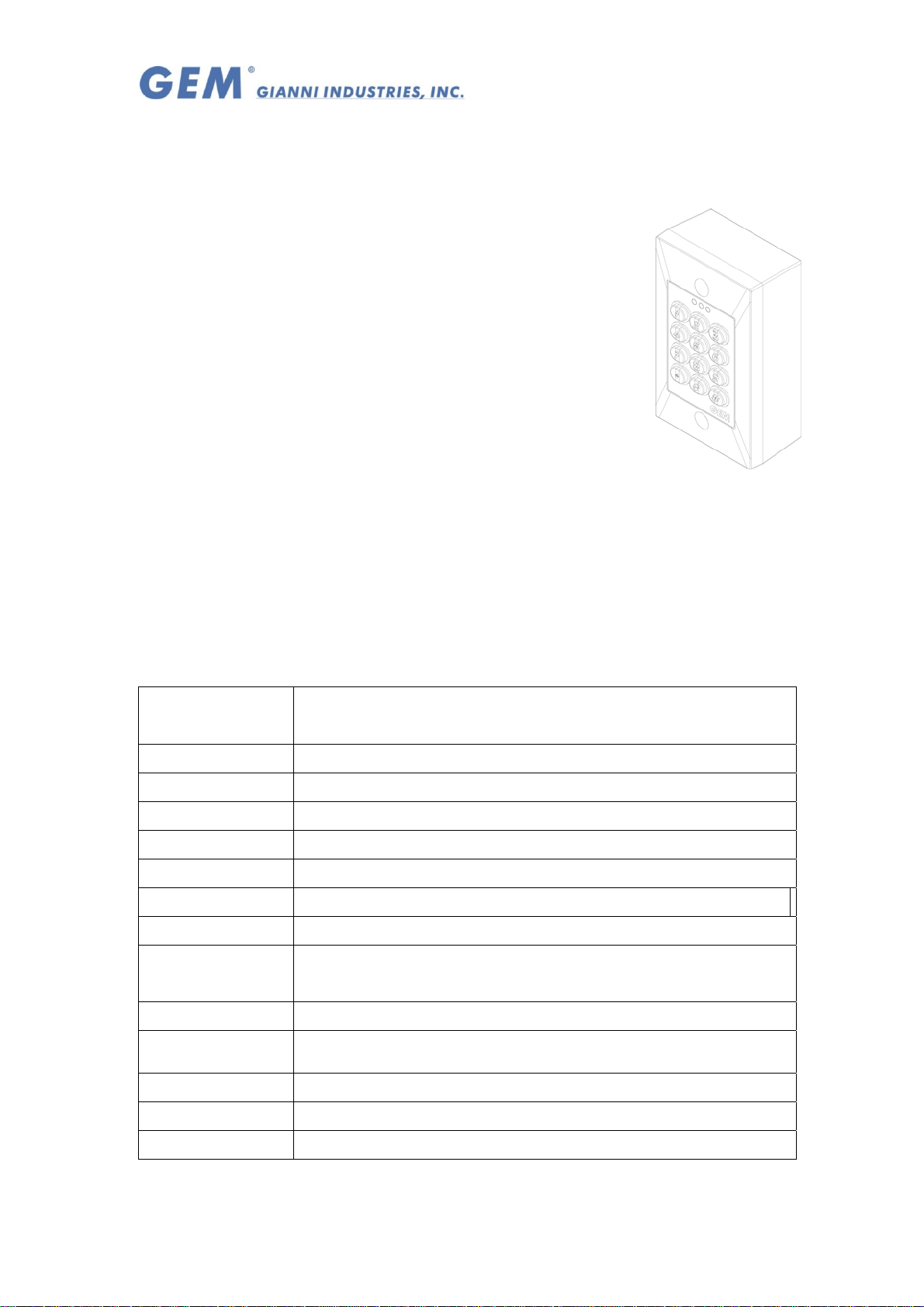
ST-630E Stand-Alone Access Control
Operation Manual
Ⅰ Features
z Master Card and Codes
z Auto Reset Function
z Security System Setting/ Release
Synchronize with Security System
z
z Entering/Exiting Programming Mode: Only Proximity
Codes + Proximity, Codes or Proximity
z Door Status Monitor Function
z
Anti Pass Back Function
z
Emergent Access Alarm, Time Delay Alarm and Forced
Door Alarm
z Dual relays programmable On/Off or pulsed or latched mode
z LED Indicator to distinguish the status
z Use for all kinds of the electric lock.
output
Ⅱ. The Specifications:
Part No. ST-630E
Connection Connection/ Stand-alone
/Users 1000
/Record Volumes 1000
Reader Application WG26,WG34
Keys 12 Keys (0-9,*,#)
Interface RS485
Proximity Distance About 125 and 15 cm/13.56 for around 7 cm
Proximity
125Khz (EM)
Frequency
Indicators 3 LEDs
Dimension (mm) 114(L) x 69.5(W) x 10(D)mm
Operating Voltage:
Temperature -5 C-60 C
Humidity
Copyright All Rights Reserved. Page 1 of 5
P-MU-ST-630 Ver. A Publish: 2009.01.08
5%-95%(Non-condensing)
12 VDC
Page 2
Indicators Status and Default Val ue
Ⅲ
Beep & LED indication:
Mode
Yellow(flashing
slowly)
Normal
LED
Programming
Normal
Beep
Programming
Factory Default Setting:
Green On Valid entry, door relay active
Red
Yellow(flashing
Quickly)
Red flashing
Quickly)
1 Beep
2 Beep Invalid cards, Mistake Codes
1 Beep Valid Entry, exit the Program Mode.
2 Beep Input mistake or other failure operation
Signal
Status
Power-on, stand-by
Warning, invalid card or code, tamper, alarm relay
active
Enter Programming Mode.
Card read, or clear the memory
Invalid card、keypress、entry program mode
Access Mode Card only (0000)
Card Memory All Bits
Transaction Memory (MAX 1000 cards)
Master codes (Master Password) *123456#
(All) Functions of Alarm Clear the function (00)
Door Relay Time 5 Seconds
Key Timeout 5 Seconds
Awaiting code timeout 5 Seconds
Programming mode timeout 25 Seconds
Copyright All Rights Reserved. Page 2 of 5
P-MU-ST-630 Ver. A Publish: 2009.01.08
0 pcs
Page 3

Ⅳ Operation Instruction:
*xxxxxx#
* # Exit Program Mode
01*xxxxxx xxxxxx # Change Default Password, Press twice new 6-digital Codes
02*xxxx #
05*xxx# Access only with the password, 0000-Unavaliable (Default, 0000)
12*XXXX*XXXXX#
13*xxxxx*XXXXX*N #
Enter Program Mode,Enter 6-digital Codes,(Default 123456)
Controller Station Setting[001-254]
Adding or Revised the Cards No. 10*xxxx*XXXXXXXXXX #
Slot Position =00001~01000 and enter the 10 digital Cards No.
Adding the batch series Cards No.. XXXX=the beginning position
*XXXXX=the quantities of the batch series card No.
(The access mode is for Card Only) (ps. x≦01000)
Modify the cards access parameter
xxxxx= The beginning slot position
XXXXX= the ending slot position From=00001~01000
N is 0= Access not allow,1=Card only, 2=Cards or Code,
3=Card & Code, 4= Clear card information
(When modify the Mode to “Card or Code” or “ Card & Code”,the
default Code is 0000.
14*xxxxx*XXXX#
15*99# Clear all Cards (Not including Master Cards)
17*xxxxxxxxxx#
21*xxx# Alarm Time Delay Setting xxx=000~255 Seconds
22*xxx#
26*xxxxx*XXXXX#
Set the position of the Code; xxxxx=slot position XXXX=4-digital
Code (Position =00001~01000)
When forget the Cards slot position,can clear the cards information
by enter Cards No..
Dual relays programmable time delay xxx=000~250 Seconds
(External Relay for Security System)
(000 Latched Operation) (Default is 15 Seconds)
Master Cards Setting x=(1 or 2). 2 Master Card available 25*X#
In the normal status, proximity the Master cards to Program Mode.
Security Cards arrange Setting XXXXX=00001~01000 .The arrange
of the No. should be continuing which can’t skip the No.
x=0 General Setting Mode (Default x=0) 30*x#
x=1 Card Only. Access the door by reading cards that no matter the
cards are set into the system or not.
Anti Pass Back Function
32*x#
33*x#
Copyright All Rights Reserved. Page 3 of 5
P-MU-ST-630 Ver. A Publish: 2009.01.08
x=0/ OFF X=1/ ON
Two Doors Synchronize x=0 OFF X=1 ON,Access
Page 4

Controller and Reader can open different doors.
34*99#
35*x# (for connecting
controller)
38*x#
51*99#
55*99#
70*X# [For LCD series] X=0 Screen Backlight ON ,x=1 Screen Backlight Off automatically
71*XXXXXX XXXXXX #
Reset the function of
x=1=
access record to duty
x=0= access record Not to Duty
(x= default is 0)
x=0 Green LED is controlled by Controller x=1 Green LED is
controlled by external system
(The second Relay contact to the Door Status and
Green LED flash can
Reset to Default, and clean the controller memory to the factory
default
Add New Cards,read card once and 1 Beep heard for adding the
new card. Read card twice and 2 Beep heard to delete the cards.
(After add Cards,the default access mode is “Card Only”)
Emergent Code Setting,Enter twice 6-Digital Code。
Enter the Code can link to the other relay to activate the external
Anti Pass Back.
negatron (-) ,
synchronize with Security System.
system. 22*xxx # for setting the active time. (second)
xxx=000~255 Seconds
72*xxx#
73*x #
74*x# X=1 Door Left Open Alarm and Force Open Mode are ON; X=0 OFF
76*x#
99*
Door Left Open Alarm Time Delay - The door does not close after the
limited time, and the controller will output the alarm.
x=1 Enter the emergent code or press 99* with Security Cards, the
relay of the controller/ ON; X=0 OFF
X=1 Emergent Alarm /ON,x=0 OFF
When setting or Release the External Relay, Please enter the
codes99*and then read the security card.
(Operating in the Normal Mode.)
Ⅴ、 Wiring diagram:
Copyright All Rights Reserved. Page 4 of 5
P-MU-ST-630 Ver. A Publish: 2009.01.08
Page 5

Copyright All Rights Reserved. Page 5 of 5
P-MU-ST-630 Ver. A Publish: 2009.01.08
 Loading...