

Page 1
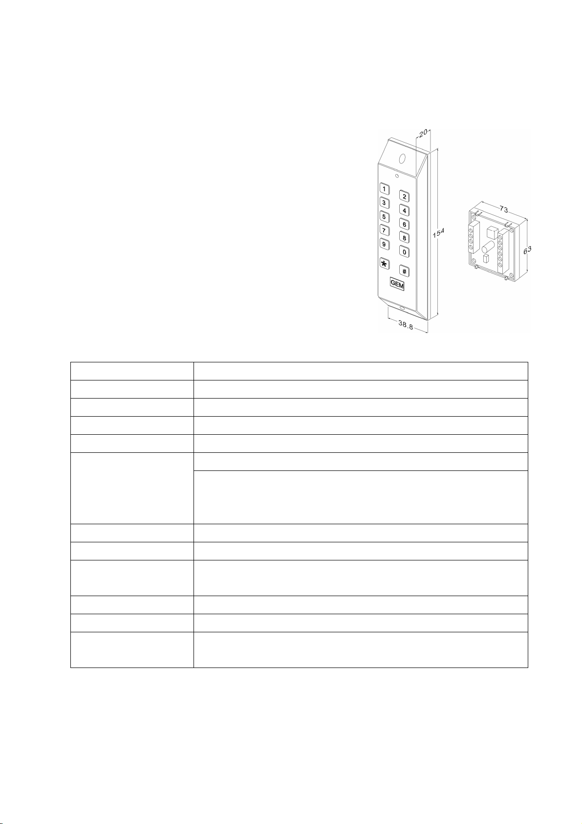
DG-100 Split Digital Keypad
Operation Manual
Ⅰ. Features
1. Memory volume up to 99 PINs
2. Split controller and keypad for high security
3. Up to 29-digit-fuzzy-code password protected design
4. Deftly dimension for narrow jamb
5. 1 LED indicator & buzzer for status indication
6. Fully programmable via keypad
7. Lockout function
8. Metal casing for enhanced safety and durability
9. Keypad with beep sound
Ⅱ. Specifications
Operating Voltage 12VDC
Current Draw Holding: 15mA, Pull in: 70mA @12VDC
Keypad
Output
Relay Electric Current
Memory Volume
Relay Strike Time 01~99 seconds or Toggle Mode (00)
LED Status Indication 3 colors LED indicator display (Red/Yellow/Green)
Lockout Function
Ambient Humidity 5%~95% (Non-condensing)
Operating Temperature
EPROM
6X2 matrix keypad (0~9,*,#)
Relay(Dry contacts: N.O./N.C./Com.)
1A MAX @24VDC ;0.5A @ 120VAC
99 PINs
*000:master code
*001~099:PINs (user codes)
*100:relay strike time
The controller will be lockout for 60 seconds upon 30 consecutive master
codes or invalid PINs attempt. (Keypad without beep sound)
-20℃~+70℃
Non-volatile memory allows remaining all setting codes in the event of total
power failure.
Copyright All Rights Reserved.
P-MU-DG100-4C Ver.D Publish:2009.12.02 Page: - 1 -/ 4
Page 2
Ⅲ. Indicator Status & Default Setting Parameters
Beep & LED Indication:
Mode Status
Green On Relay Strike Time
LED
Beep
Red On Power on
Yellow On In setting mode
1 Beep Key press, valid PINs
2 Beeps Enter or exit setting mode
3 Beeps Incorrect input
5 Beeps Master Code back to 1234 (cleared settings)
Factory Default Setting:
Master Code 1234 (4 digits)
Relay Strike Time 5 seconds
Pressed Key Time Delay 30 seconds
Setting Mode Time Delay 50 seconds
Ⅳ. Operation Instruction
Enter Setting Mode
Enter the master code twice (Default value:“1234”) to enter setting mode (2 Beeps)
Note: 1. After 50 seconds if no data entered, it will automatically exit the setting mode.
2. The controller will be lockout for 60 seconds upon 30 consecutive master codes or invalid
PINs attempt.
Exit Setting Mode
Press # to exit setting mode or after 50 seconds if no data entered, it will automatically exit the setting
mode.
Add new PINs (In setting mode)
1. Enter slot position*001(*001~*099)
2. Enter the 4-digit PINs (1 beep)
3. Press “#” to exit setting mode
Note: 1. “0000”, “1234” and any master code cannot be used for PINs
2. Up to 29-digit-fuzzy-code password protected design
e.g. Press 59632548745233058403256905194→open the door (The valid PINs are “5194”)
Copyright © Gianni industries, inc. All Rights Reserved.
P-MU-DG100-4C Ver. D Published on 2009.12.02 Page: - 2 -/ 4
Page 3

Set the Relay Strike Time (In setting mode)
1. Press *100
2. Press 05(01~99)(1 beep)
Press 05 will set the relay strike to 5 seconds, relay set to toggle mode
3. Press “#” to exit setting mode
In Toggle mode, the relay will switch between N.C. contact and N.O. contact upon enter PIN once.
Delete PINs (In setting mode)
1. Press *006 (e.g. code to delete)
2. Press 0000(1 beep)
3. Press “#” to exit setting mode
Change Master Code (In setting mode)
1.Press *000
2. Enter 4-digit new master code (1 beep)
3. Press “#” to exit setting mode
Master Code reset to default value “1234”
1. Insert the reset jumper into 1-2 (5 beeps)
2. Master Code reset to default value “1234” (must release the jumper as soon as 5 beeps, otherwise
could clear all PINs)
3. Insert the jumper back into 2-3
(Note: Only after 5 beeps, the system will execute the reset process)
Master Code reset to default value“1234” and Clear all PINs
1. Insert the reset jumper into 1-2 (5 beeps)
2. Master Code reset to default value“1234”
3. Clear all PINs (wait after 5 seconds) (5 beeps)
4. Insert the jumper back into 2-3
Copyright © Gianni industries, inc. All Rights Reserved.
P-MU-DG100-4C Ver. D Published on 2009.12.02 Page: - 3 -/ 4
Page 4

Bla ck
White
Green
Bla ck
White
Green
Res et
Res et
12312
3
Electric Lock
Master Co de reset to
default value or cl ear
default value or clear
Ⅴ. Wiring Diagram
Fail-Safe Mo de
Electric Lock
Fail S ecure Mode
-
Power Supply
Power Supply
Exit Button
Exi t Button
Vin
Vin
+
-
N.O .
COM
N.C .
P
P
+
-
N.O .
COM
N.C.
P
P
PB
RC
PB
RC
+
-
R
+
-
R
Vout
Vout
Blu e
Red
all PINs
Blu e
Red
Mas ter Code reset t o
all PINs
Note:
1. It is suggested to use #22~26 AWG insulation wire.
2. The door strike or relay must have a varistor or a diode across the door strike terminals to suppress
the back EMF of the strike – failure to do so will damage the relay contacts and electronic components,
or even burns the controller.
Warranty:
The product is warranted against defects in material and workmanship while used in normal service for a
period of 1 year from the date of sale to the original customer. The GEM policy is one of continual
development and improvement; therefore GEM reserves the right to change specifications without notice.
Copyright © Gianni industries, inc. All Rights Reserved.
P-MU-DG100-4C Ver. D Published on 2009.12.02 Page: - 4 -/ 4
 Loading...