

Page 1
EASIPROX St and Alone Reader
Operation Manual
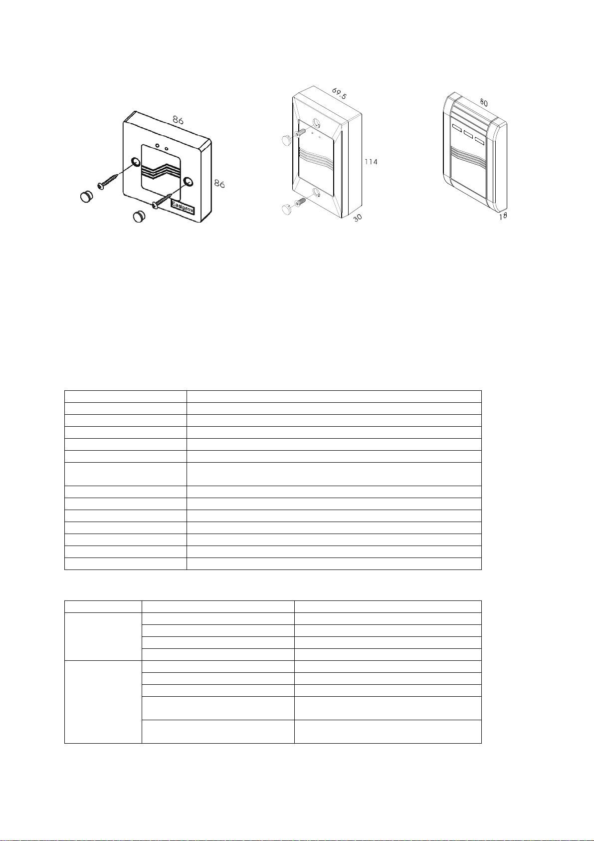
114
Unit: mm
EASIPROX EASIPROX-ANSI EASIPROX-980-40
I. Features
1. Memory volume up to 2000 proximity cards/tokens. Reading time approx. 0.5 seconds.
2. Programming via Master Card.
3. Preventing re-entering the same card.
4. Non-volatile memory stores all cards even in the event of total power failure or when the reader is
not in use for a long time.
5. Epoxy sealed. Standard size of single-gang box.
II. Specification
Operating Voltage 12 VAC/VDC
Current Draw Pull In: 70 mA/12 VDC; Holding: 45 mA/12 VDC
RF Frequency 125 KHz (ABA form code)
Read Range 10~15 cm (depending on local installation conditions)
Input 1 contact for Request-To-Exit button
Output 1 relay (Dry contacts: N.O./N.C./Com.)
LED Status Indication 2-LED indicators (Yellow & Green / Red); 3-LED indicators
(Yellow, Green, Red)
Memory Volume 2000 proximity cards/tokens
Format EM-400x 64-bit Standard R/O or Compatible
Relay Rating Max. 5A/250 VAC
Relay Strike Time 0.7 ~ 42 seconds
Ambient Humidity 5%~95% (Non-condensing)
Operating Temperature -20°C~70°C
EMC Specification Meet CE requirement
III. LED Status Indication
Mode Signal Status
Standby
Programming
Yellow & Green LED flash No Master Card (empty memory)
Yellow LED On Standby
Green LED On Relay strike time
Red LED On Invalid card
Green LED flash Add cards
Red LED flash Delete cards
Yellow & Red LED flash Clear memory
Yellow LED flash Adjustment of relock time (1 ~ 60
flashes, 0.7 ~ 42 seconds)
Green LED flash Clear all memory (including Master
Card)
Copyright © Gianni Industries, Inc. All Rights Reserved.
P-MU-EASIPROX Ver. F Published on 2011.02.14 Page: 1/ 4
Page 2
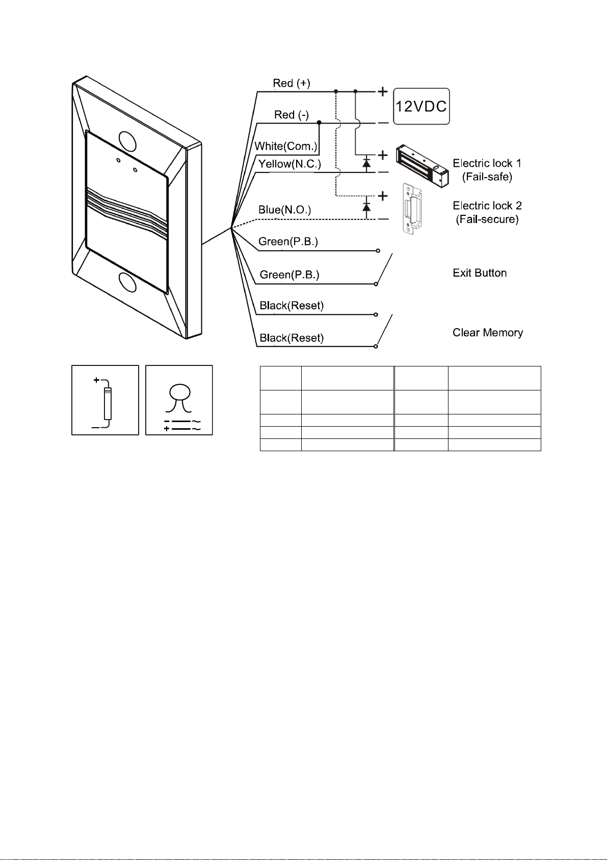
IV. Wiring Diagram
For DC use only For AC/DC
Note:
1. It is suggested to use #22~26 AWG insulation wire.
2. It is suggested to use a linear power supply unit to prevent the reduction of reading range.
3. The door strike or relay must have a varistor or a diode across the door strike terminals to suppress
the back EMF of the strike. Failure to do so will damage the relay contacts and electronic components
, or even burn the controller.
4. Exit button is at N.O. contact.
V. Operation Instruction
1. Set Master Card
Yellow and Green LED flash indicates that the memory is empty. The first card read by the reader
will be the Master Card.
Read the Master Card (Yellow LED stay on), enter standby mode
Note: The same Master Card can be used on more than one reader.
2. Add new cards
1. Read Master Card once (Green LED stay on for 3 seconds, then flash), enter adding card mode
2. Read the new card(s) (relay active → successfully adding the new card)
3. Read Master Card once (Green LED off, Yellow LED stay on), back to standby mode
Note: It is suggested to use the card of ABA form codes and make a list of the cards added to the
reader.
3. Delete cards
1. Read Master Card twice within 2 seconds (Red LED stay on for 3 seconds and flash), enter
deleting card mode
2. Read the card(s) (Green LED stay on → successfully delete cards)
3. Read Master Card once (Red LED off, Yellow LED stay on), back to standby mode
Copyright © Gianni Industries, Inc. All Rights Reserved.
P-MU-EASIPROX Ver. F Published on 2011.02.14 Page: 2/ 4
Red 12 VDC
(polarity free)
Red 12 VDC
(polarity free)
White Com. Black Clear all memory
Yellow N.C. Black Clear all memory
Blue N.O.
Green Exit Button
Green Exit Button
Page 3
4. Clear all memory
1. Read Master Card 3 times, each time within 2 seconds of interval (Yellow & Red LED stay on for
3 seconds and flash), enter clearing memory mode
2. Read any EM-400x 64-bit R/O compatible card except Master Card (Green LED flash → in the
process of clearing all memory, including Master Card)
3. Empty memory and back to default value (Yellow & Green LED flash)
4. Follow step 1 to set new Master Card
If the Master Card is lost, follow the steps below to clear all memory:
1. Turn off the power
2. Connect the two black cables and turn on the power
3. In the process of clearing all memory, including Master Card (Green LED flash)
4. Disconnect the two black cables (Yellow & Green LED flash → memory is empty)
5. Set relock time
1. Read Master Card 4 times, each time within 2 seconds of interval (Yellow LED stay on for 3
seconds, then flash), enter relock time setting mode
2. Each flash indicates 0.7 seconds. If the relock time is set to 5 seconds, after 7 flashes, read the
Master Card once. (Yellow LED stay on), back to standby mode
Note: The longest relock time is 42 seconds (60 flashes). After 60 flashes, the Yellow LED will
automatically stay on and go back to standby mode.
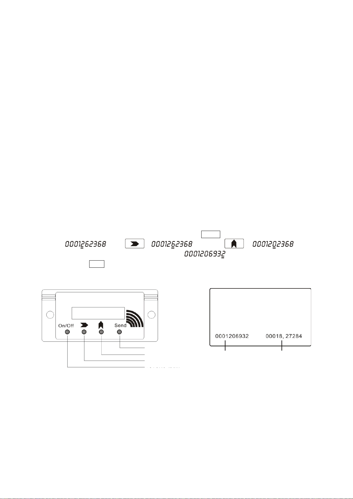
VI. TS-980 Tag Simulator (optional)
TS-980 Tag Simulator simulates any card/tag number stored in the memory of the reader. When you
plan to delete a lost card/tag from the memory, Tag Simulator is used to transmit the number of the lost
card/tag to the reader and then you can begin to delete it from the memory.
For example: delete the card, ABA code 0001206932. Press On/Off continuously. When the screen
displays , press → , and press → .
Repeat the preceding step. When the screen displays
, and the reader enters deleting
card mode, press Send (The distance between the Tag Simulator and the reader must be within 3 cm.)
Card deletion is completed.
Send card No.
0to9
Next digit
Power
Decimal ABA form code, decimal
Warranty
The product is warranted against defects in material and workmanship while used in normal service for
a period of 1 year from the date of sale to the original customer. The GEM policy is one of continual
development and improvement; therefore GEM reserves the right to change specifications without
notice.
Copyright © Gianni Industries, Inc. All Rights Reserved.
P-MU-EASIPROX Ver. F Published on 2011.02.14 Page: 3/ 4
Page 4

Annex: User List
Slot Number ABA Form Code User Name Note
Copyright © Gianni Industries, Inc. All Rights Reserved.
P-MU-EASIPROX Ver. F Published on 2011.02.14 Page: 4/ 4
 Loading...