

Page 1
AD-425S Automatic Door Operator
Instruction Manual
General Safety Precautions
z This instruction manual is intended solely for use by qualified professionals. All
installations, electrical connections and adjustments must follow the installation
instructions.
z Please read this manufacturer's instructions carefully before installing this unit. Incorrect
installation may result in severe personal injury and/or damage to property.
z Packaging materials (plastic and polystyrene, etc) should be disposed of without causing
environmental damage and should be kept out of reach of children.
z Do not install this unit in a chemical explosive environment or atmosphere to prevent a
risk of explosion. The location of this unit is important in achieving proper performance
and normal operating life. This unit should be installed in a safe operating condition
z Make sure the construction‘s strength and stability are up to standard. Manufacturer will
not be held responsible for any damage resulting from incorrect use of this unit.
z These safety devices (e.g. photocell and emergency stop) must follow the technical
safety regulations and current safety standards, including limiting of forces and speeds to
ensure the door operator works very well at all times.
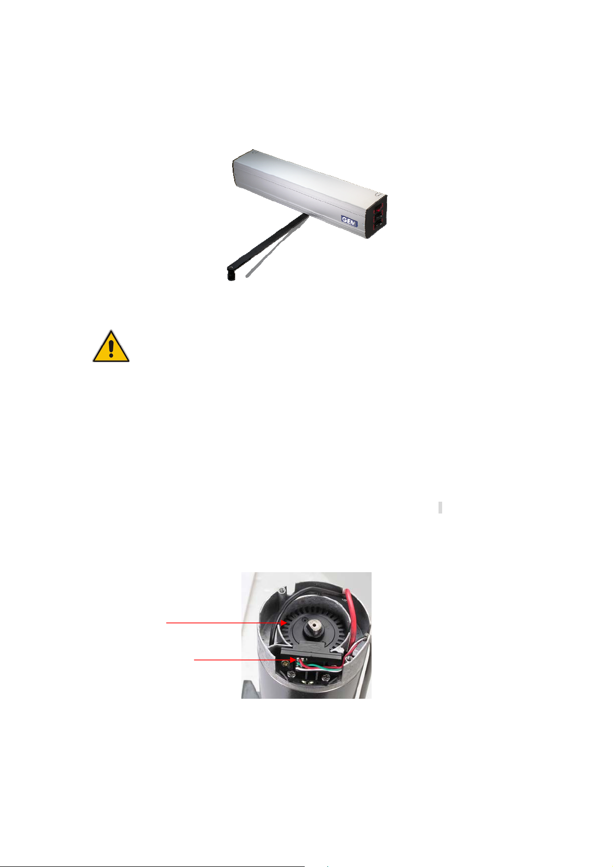
Encoder
Photocell
z The safety devices must protect any areas where the risk exits of being crushed, cut or
gagged or where there are any other risks generated by the motorized door or gate.
Apply hazard areas notices required by applicable regulations.
z Each installation must clearly show the identification details of the motorized door/gate.
Copyright All Rights Reserved.
P-MU-AD425S Ver. A Publish:2008.07.11 Page: 1/ 20
Page 2

z Make sure the voltage specified as correct for the device.
z Must provide at least 10 seconds rest time between every restarting cycle to ensure
z Make sure to turn the power off before installing and checking this unit and to avoid the
adequate residual current can be returned to power system.
risk of fingers that are in contact with the electronic components. External
interconnection wiring should be performed wearing the antistatic glove.
Security S tatement
According to operating instructions, motorized door installer and the manufa cturer of
the machinery have the same obligations:
z The technical documents and the annex to the AD-4 25S Automatic Door Operator must
be kept and placed at the disposal of competent national authorities for at least 5 years
from the manufacturing dates. CE attestation of conformity should deliver it to the
customers.
z Should you have other queries, please refer to the http://gianni.tw
full details and other relevant documentations.
to download AD-425S
Manufacturer's Declaration
Gianni Industries, Inc.
Address: No. 306-1 Hsin Shu Road, Hsin Chuang, Taipei, Taiwan 242
E-mail:info@gianni.com.tw
http://gianni.tw
Herewith declares that AD-425S Automatic Door Operator for swing doors: (One way
direction only.)
z AD-425S Automatic Door Operator can not be installed with other mechanism except
electric door locks.
z Conformity with other CE directives: Electromagnetic Compatibility Directive
2004/108/EC(EN61000-6-1、 EN61000-6-3 、EN61000-3-2、 EN61000-3-3)
z Product life: 5 years
z Product should be operated under the recommended door weight. A reduction in
performance is to be expected when the access is made to operate at the maximum
permissible weight.
z Service class, product operation times and the number of consecutive cycles have been
statistically analyzed to determine under average operating conditions, and it does not
represent for use under a special condition. (See Figure 1)
z The characteristic performance of door operation may be affected by different
independent variables like friction, offset (balancing), environmental factors and so on.
These factors may change the performance of the door operator’s working life or parts.
Furthermore, the assembly must be considered and enables infinite durability and
continuous operation.
Copyright All Rights Reserved.
P-MU-AD425S Ver. A Publish:2008.07.11 Page: 2/ 20
Page 3
All Packing materials
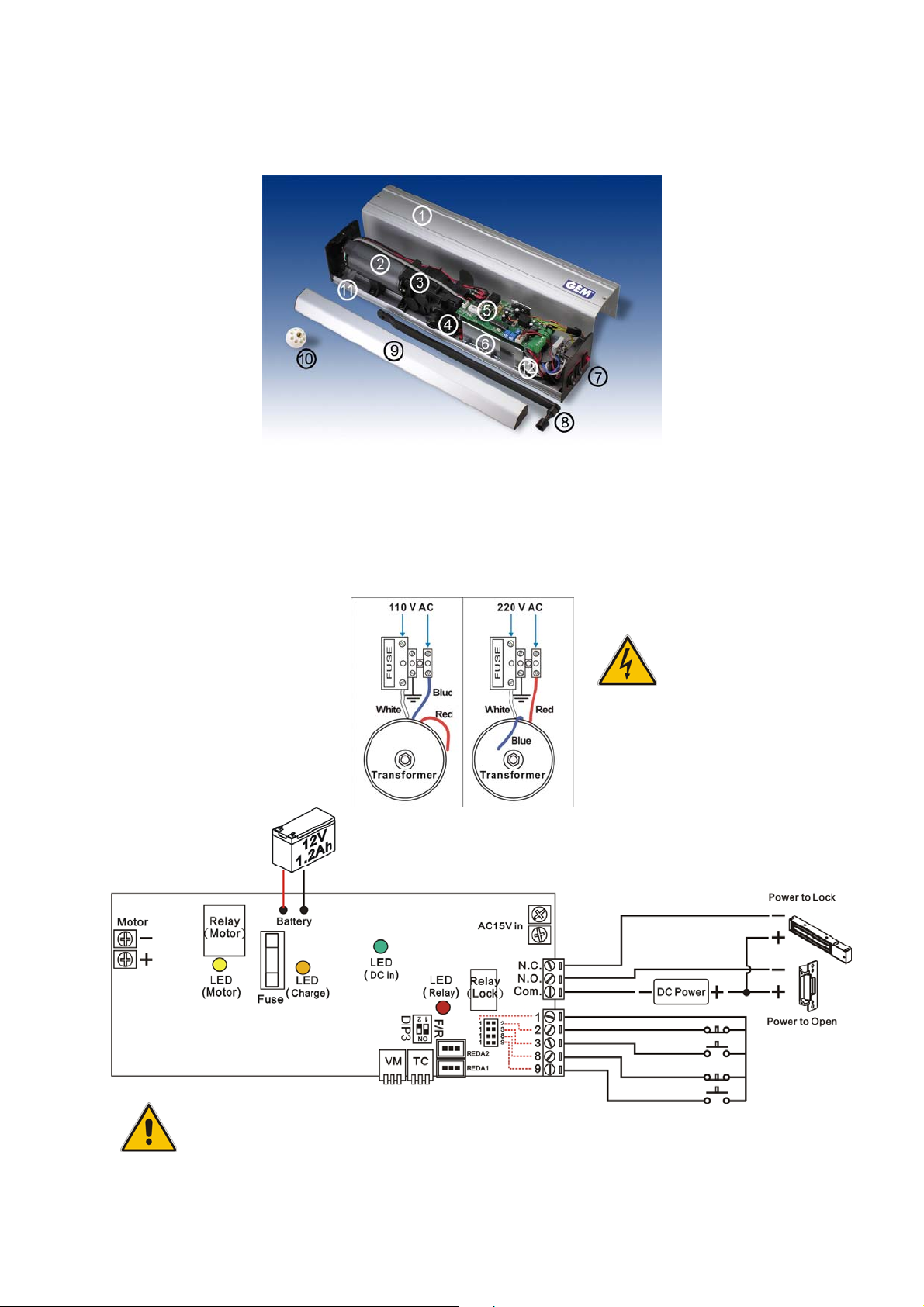
1. Construction Name
1 Cover ○2 Motor ○3 Reducer ○4 Square Couplings ○5 Control Board ○6 Battery
○
7 Power Switch ○8 Operating Arm ○9 Sliding Rail ○10 Stopper Ball ○11 Baseplate
○
12 Transformer
○
2. Control Board
Make sure the voltage
specified as correct for the device.
For safety reasons, we recommend user not to install this operator with a Fail-Secure
Electric Locks (Power to open) in case of emergencies or power interruption s.
Copyright All Rights Reserved.
P-MU-AD425S Ver. A Publish:2008.07.11 Page: 3/ 20
Page 4
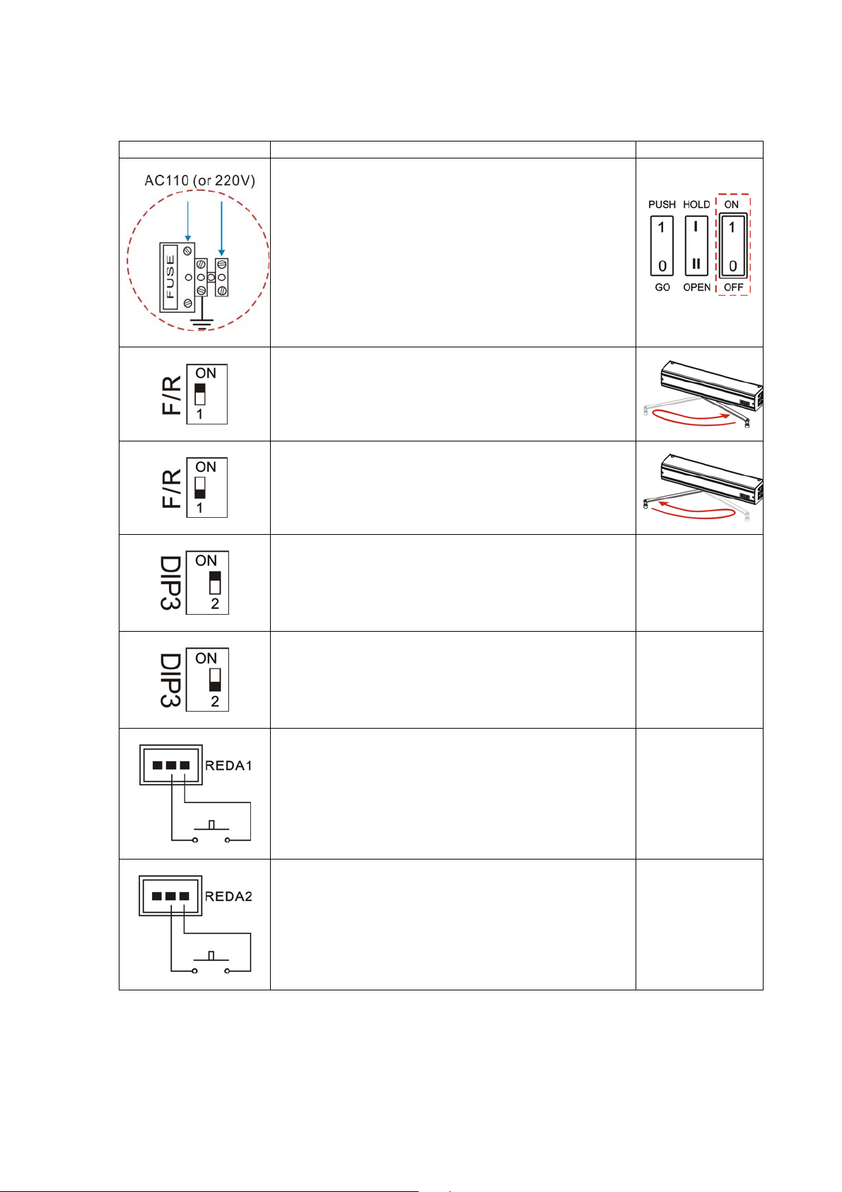
3. Control Board Guide
Input/Output Contact Explanation Remark
Make sure the input is used correctly (AC110 or 220V).
When turn on the power switch, it enters a learning
mode.
AD-425S Operating Arm turns clockwise. (See Figure
5~8)
AD-425S Operating Arm turns counter-clockwise. (See
Figure 5~8)
DIP3 switch ON, when the external pressure force either
“WIND” or “MAN MADE FORCE” occurs, AD-425S will
automatically open and close.
DIP3 switch “2”, when the external pressure force either
“WIND” or “MAN MADE FORCE” occurs, AD-425S can
be manually opened and closed.
REDA1 internal connector links up the control unit.
REDA2 external connector links up the control unit.
Power Switch
When Lock is
opened and wait
up to
0.7seconds, the
Motor will be
activated.
When Lock is
opened and wait
up to
0.7seconds, the
Motor will be
activated.
Copyright All Rights Reserved.
P-MU-AD425S Ver. A Publish:2008.07.11 Page: 4/ 20
Page 5
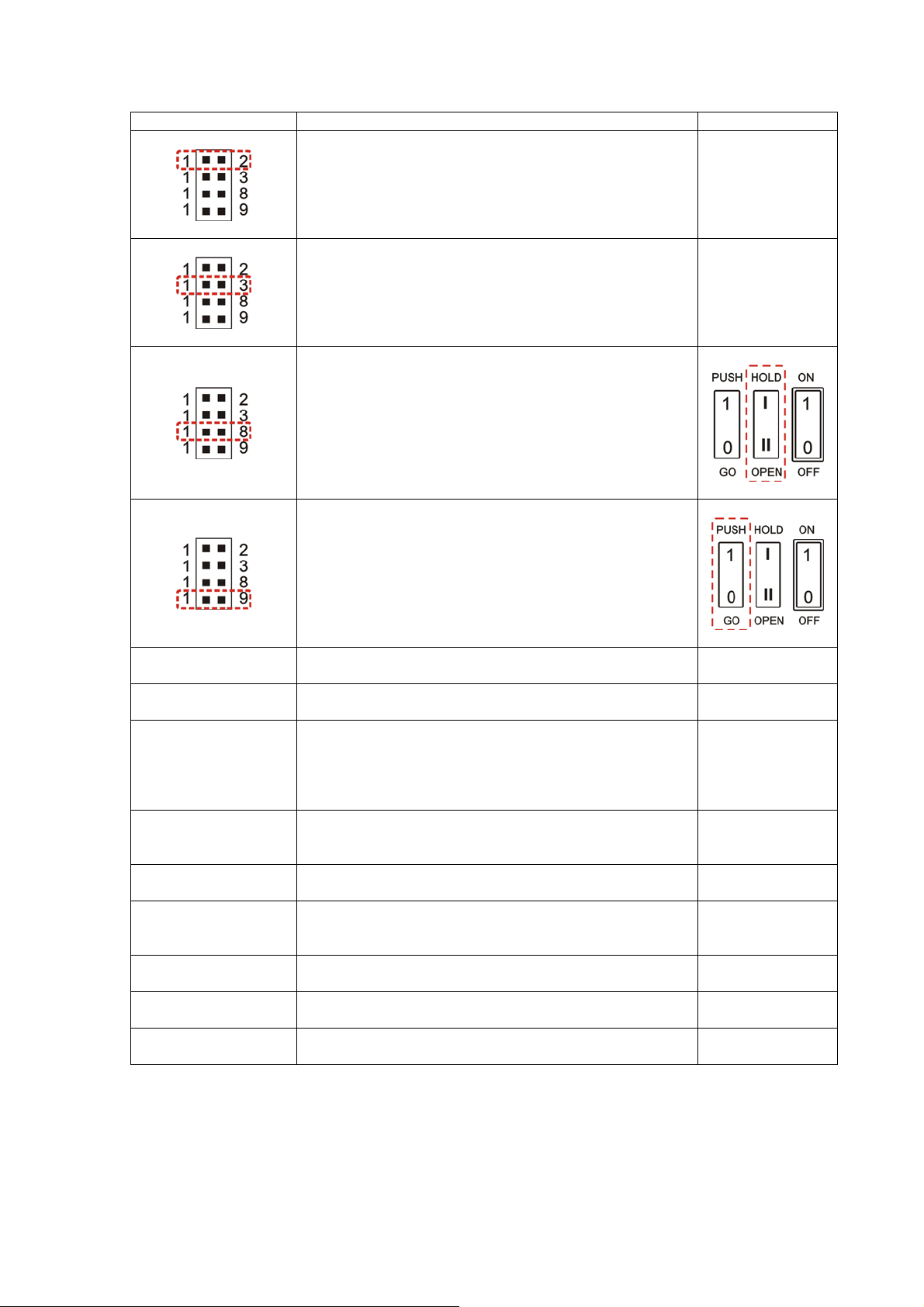
Input/Output Contact Explanation Remark
Jumper 1-2 is N.C. contact. N. C. (default)
Jumper 1-3 is N.O. contact. N. O. (default)
Jumper 1-8 is N.C., or using the “OPEN” switch.
AD-425S becomes automatic mode. When the
connector is N.O. or using the “HOLD” switch, and then
change to manual mode.
Jumper 1-9 is N.O., or using the “GO” switch.
AD-425S becomes manual mode. When the connector
is N.C. or using the “PUSH” switch, and then change to
automatic mode.
LED (Relay)
LED (DC in)
Relay(Lock) Action indicator. See page 3
PCB power status indicator. See page 3
This battery has
Battery Contact and
LED (Charge)
LED (Charge) indicates the battery charge is working
properly. The optimum operating temperature for the
rechargeable battery is 5℃ up to 40 ℃.
an expected life
of 250 recharge
cycles at full
charge.
Battery
BATTERY Battery Contact.
Specification (12
V ,1.2 Ah)
LED (Motor)
N. C.
N. O.
Com.
AC 15V IN
Motor power status indicator. See page 3
N. C. is a normally closed contact, and it is for
fail-safe (Power to Lock) Electric Locks.
N. O. is a normally open contact, and it is for
fail-secure (Power to Open) Electric Locks.
Com. contact is a dry contact compatible with N. O. and
N. C. contacts.
The 15V AC power is transformed from 110 or 220 VAC
by the transformer to the Control Board.
All GEM electric
locks are
suitable.
Copyright All Rights Reserved.
P-MU-AD425S Ver. A Publish:2008.07.11 Page: 5/ 20
Page 6
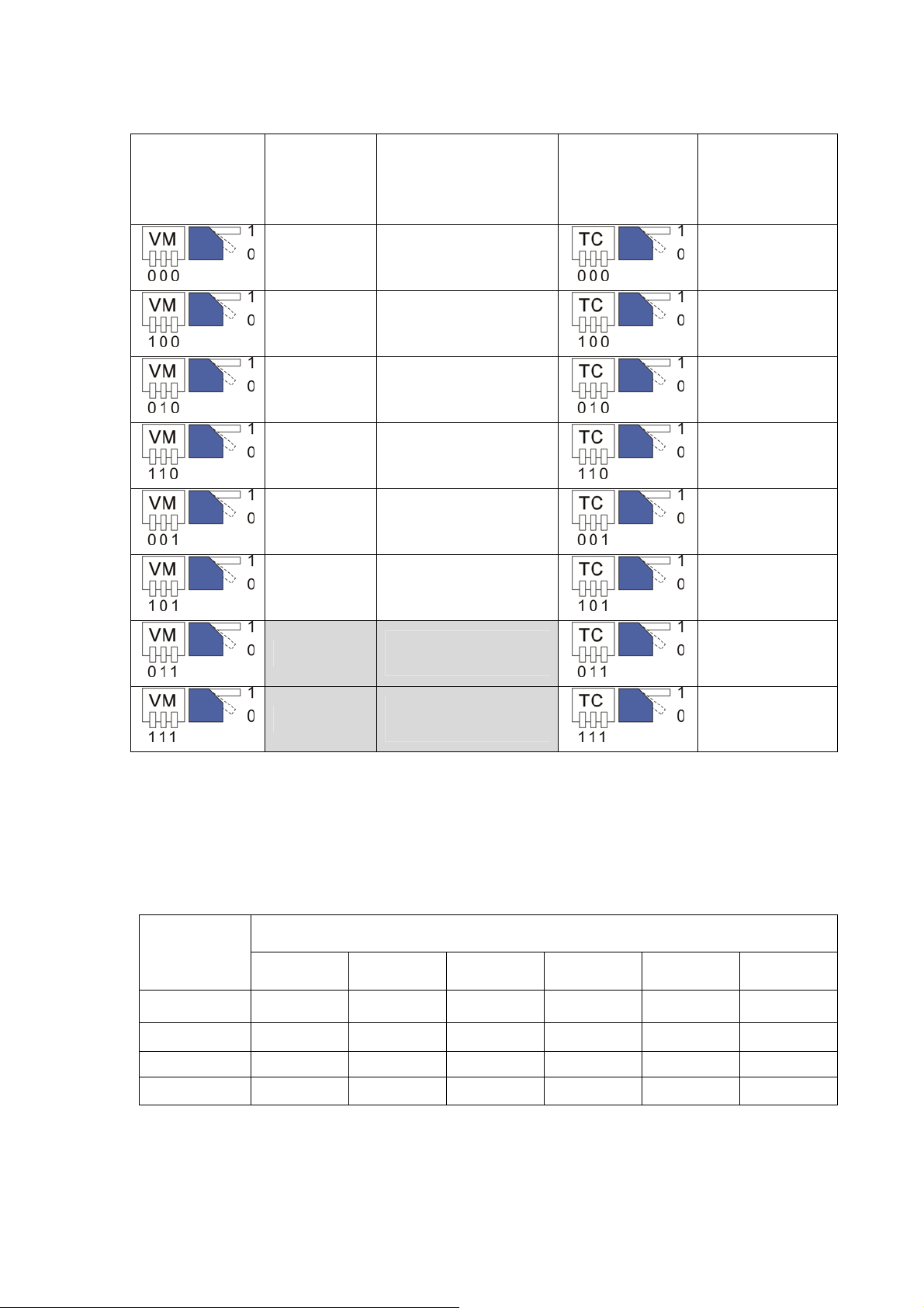
The opening, closing and maintain -open time illustration table.
VM
(Opening and
Closing Time
Adjustment )
Opening and
Closing
Operating
Time
Total Opening and
Closing Time (VM+
Brake Time)
TC Time
(Maintain -open
time adjustment)
Maintain -open
time
(See Figure 4)
2 4.5
3 6.0
5 8.0
7 9.5
2
4.5 (With high torque
output)
3
6.0 (With high torque
output)
5
8.0 (With high torque
output)
1
5
10
15
20
25
30
7
9.5 (With high torque
output)
35
z For the wider door leaf, we suggest that you can extend the opening and closing time or
adjust the high torque output. For the 95cm~120cm door width, please refer the gray
region for setting. The high torque output enhanced the door stability.
z The opening operation based on 90° angle; however, there would be time dif ference from
the setting angles.
z Please refer to the below table for TC settings.
Door width
(cm)
50 kg 60 kg 70 kg 80 kg 90 kg 100 kg
Door weight (kg)
75 cm 20 s 20 s 22 s 22 s 25 s 28 s
85 cm 20 s 20 s 22 s 22 s 25 s 28 s
100 cm 22 s 22 s 24 s 24 s 27 s 30 s
120 cm 22 s 22 s 24 s 24 s 27 s 30 s
Copyright All Rights Reserved.
P-MU-AD425S Ver. A Publish:2008.07.11 Page: 6/ 20
Page 7

5. Specification
Power Input
Current (See Figure 2) 3.5A max., 0.6A average
Torque 30Nm
Opening/Closing time (VM)
Maintain - Open time (TC) 1~35 seconds
Battery Specification 12V 1.2AH
Temperature -20 ~+55℃℃ (Battery 5 ~40℃℃)
Degree of Protection IP 12D
Product Weight 6.5 kg
Voltage: 8~24VDC
Motor specification
Battery charge 12V=0.15A (Normal); 0.3A (Peak)
Dimensions
Door Dimensions
(Figure 1)
Maximum current : 4A
Power consumption : 65W
Maximum rotation frequency: 2400 RPM
110V (or 220V) AC,50-60Hz
4.5~9.5 s (90°)
Operator: 526(L) x 100(W) x 96(D) mm
Arm: 375 mm
Door width : 75~120 cm
Door weight : 50~100 kg
Figure 1
Door Width(cm)
Door Weight(kg)
Service Class A: average of up to 600 cycles
per day
Service Class B: average of under 200 cycles
per day
This warranty is only for our specified door leaf
width and door leaf weight.
z Figure 2: Automatic door operator power consumption graph. Wh en activated the curre nt
will increase from 0 to 3.5A, and will decrease to 0.5~0.6A afterward. The deceleration
time will cause the current up to 1.8A.
Figure 2
Copyright All Rights Reserved.
P-MU-AD425S Ver. A Publish:2008.07.11 Page: 7/ 20
Page 8

Installation instructions
z Refer to figure 3 for in-swing door (right-hand).
Figure 3
z Opening, Closing action time and Maintain time illustration. AD-425S will be
automatically counted the round trip distance and can be adjusted the opening, closing
and break time.
Figure 4
Opening angle: 90 degrees.
Beginning
Destination
Brake for wall blanking function.
VM action time is the opening and closing time.
TC Maintain time of 1-35 seconds
.
Prepare the installation
To mount the AD-425S depends on the direction way of the doors, out-swing, in-swing, rightopen and left-hand doors by adjusting the F/R switch and the direction of the Operating Arm.
For the safety reason, AD-425S must be installed indoor.
Copyright All Rights Reserved.
P-MU-AD425S Ver. A Publish:2008.07.11 Page: 8/ 20
Page 9

Figure 5: For right-hand and out-swing door. F/R switch set 「ON」. Operating Arm mounts to
left-side.
Figure 6: For left-hand and out-swing door. F/R switch set 「1」. Operating Arm mounts to
right-side.
Figure 7: For right-hand and in-swing door. F/R switch set 「1」. Operating Arm mounts to
left-side.
Figure 8: For left-hand and in-swing door. F/R switch set 「ON」. Operating Arm mounts to
right-side.
Figure 5 Figure 6 Figure 7 Figure 8
To mount the operator on a right-hand door, Operating Arm mounts to left-side. (See Figure 9)
To mount the operator on a left-hand doo r, Operating Arm mounts to right-side. (See Figure 10)
Mount the Operating A rm
Figure 9 Figure 10
z Required Tools
Copyright All Rights Reserved.
P-MU-AD425S Ver. A Publish:2008.07.11 Page: 9/ 20
Page 10

z Figure 11~13 showing an operator installation of a minimum door leaf width and a
maximum opening angle. The opening angle is recommend ed not excess to 120∘.
Figure 11
Figure 12 Figure 13
z Figure 14: Automatic door operator dimension
Figure 14
z Install AD-425S on an out-swing door, make sure that the distance between the header
and leaf is not more than 60mm, and the space between the header and Sliding Rail
mounting hole must be 60mm. (See Figure 15)
z Install AD-425S on an in-swing door, make sure that the distance between Square
Couplings and hinge is not more than 74mm , the space between header and the bottom
of AD-425S must be 23mm, and the space between header and Sliding Rail mounting
hole must be 39mm (See Figure 16)
Figure 15 Figure 16
z All dimensions and units are in millimeters unless otherwise specified.
z Make sure AD-425S performance is effectively; no extra door closer required.
z Warning: The AD-425S installation should regard the external and internal pressure
Copyright All Rights Reserved.
P-MU-AD425S Ver. A Publish:2008.07.11 Page: 10/ 20
conditions. To assure the pr oper operation and the finest performance, please make a
regular check for your operator.
Page 11

AD-425S Template Installation Instruction
Figure 17 Out-swing door (Right-Hand Open)
Figure 18 Out-swing door (Left-Hand Open)
Figure 19 In-swing door (Right-Hand Open)
Figure 20
In-swing door (Left-Hand Open)
Copyright All Rights Reserved.
P-MU-AD425S Ver. A Publish:2008.07.11 Page: 11/ 20
Page 12

Installation Steps Out-swing door( Right-Hand Open )
Step Figures Explanation
Place the AD-425S template to the right position on
Step 1.
the door header. See the figure presented for an
out-swing door (Right-Hand Open), more details
shown in Figure 17.
Step 2.
Step 3.
Step 4.
Mark for pilot holes.
Mark six pilot holes, one cable hole and center line.
Drill a pilot hole.
(Use the center pointer)
Step 5.
Step 6.
Copyright All Rights Reserved.
P-MU-AD425S Ver. A Publish:2008.07.11 Page: 12/ 20
Drill six Ø 9.5mm pilot holes and one Ø 18mm cable
hole.
Tap and insert a Blind Nut.
Page 13

Steps Figures Explanation
Use Allen Wrench to tighten the Blind Nut. This will
Step 7.
Blind Nuts Installation illustration
compress the screw so that it remains permanently
fixed in the hole. Repeat these steps on other Blind
Nuts. (Do not over tighten the Blind Nut.)
Step 8.
Step 9.
Step 10.
Blind Nuts installation completed.
Place the sliding rail template to the right position on
the door. See the figure presented for an out-swing
door (Right-Hand Open), more details shown in Figure
17.
Mark for pilot holes.
(Use the center pointer)
Step 11.
Drill three Ø 9.5mm pilot holes.
Copyright All Rights Reserved.
P-MU-AD425S Ver. A Publish:2008.07.11 Page: 13/ 20
Page 14

Steps Figures Explanation
Use Allen Wrench to tighten the Blind Nut. This will
Step 12.
compress the screw so that it remains permanently
fixed in the hole. Repeat these steps on other Blind
Nuts. (Do not over tighten the Blind Nut.)
Step 13.
Step 14.
Step 15.
Blind Nuts installation completed.
Insert two mounting screws. (Screw specification: 6 X
20 mm)
This is the position of Mounting Hanger.
Step 16.
Mount the automatic door operator.
Step 17.
Tighten the other 4 screws. (Screw specification: 6 X
20 mm)
Copyright All Rights Reserved.
P-MU-AD425S Ver. A Publish:2008.07.11 Page: 14/ 20
Page 15

Steps Figures Explanation
Step 18.
Step 19.
Step 20.
Tighten screws.
Insert screws (6 x 95 mm) to the Operating Arm on
Square See the figure presented for a out-swing door
(Right-Hand Open), more details shown in Figure 9.
Tighten nut at other end of screw.
Step 21.
Step 22.
Step 23.
Use the 10mm wrench to tighten nuts.
Insert pin to avoid the screws from loosing.
Slide the Operating Arm to Sliding Rail.
Copyright All Rights Reserved.
P-MU-AD425S Ver. A Publish:2008.07.11 Page: 15/ 20
Page 16

Steps Figures Explanation
Step 24.
Step 25.
Step 26.
Fix the Sliding Rail on the door leaf. (Screw
specification: 6 X 20 mm)
Slide in the Sliding Rail Cover.
Attach two Side Ends.
Step 27.
Step 28.
Step 29.
Depending on the door leaf opening angle, there may
need a Stopper Ball.
Optional electric lock, wireless push button, microwave
sensor, reader and other accessories ca n be used with
the AD-425S operator. See the Control Board guide
above on Page 3-5 to wire this application.
After the initial installation, please connect AC power
and turn the switch on.
Copyright All Rights Reserved.
P-MU-AD425S Ver. A Publish:2008.07.11 Page: 16/ 20
Page 17

Steps Figures Explanation
Step 30.
Step 31.
Step 32.
First opening movement, the AD-425S will be
automatically set the opening angle and distance.
Attach the cover.
Attach the Operating Arm cap.
Make final
settings and
adjustments
Change
battery
Please refer to page 4~6 for more details of the setting.
Battery is located on the back of Control Board.
Remove the Fixing Plug and old battery, replace the
new battery, then tighten the Fixing Plug.
Copyright All Rights Reserved.
P-MU-AD425S Ver. A Publish:2008.07.11 Page: 17/ 20
Page 18

Trouble shooting
Problem Possible Cause Solution
Make sure the Control Board and fuse are
working properly and connected properly.
No AC power
The door does not
respond.
Motor have no power
(LED motor light not on.)
Jumper 1-9, or PUSH Switch
setting is incorrect.
Door accidentally locked.
Safety contacts are open
Make sure all motor terminals are connected
properly.
Jumper 1-9 is N.O., or using the “GO” switch.
AD-425S becomes manual mode. When the
connector is N.C. or using the “PUSH” switch,
and then change to automatic mode.
Attach any flexible items (eg, rubber or others) to
the Door-stop for increasing damping capacity.
We recommend you to use the electromagnetic
lock.
Turn to “OPEN” Mode.
The door can
automatically open
but doesn’t close.
Check Jumper 1-2 (N. C.)
The automatic close function
does not respond.
Copyright All Rights Reserved.
P-MU-AD425S Ver. A Publish:2008.07.11 Page: 18/ 20
Page 19

Problem Possible Cause Solution
Contact your local distributor to check the
The door
automatically
open but doesn’t
close.
Safety devices are on
“REDA 1”, “REDA 2” contacts
are on.
Photocell and Safety Device. (keep the device
clean)
Check the “REDA 1”, “REDA 2” contacts are
working properly. Remove the obstacles.
The door
automatically opens
and closes by itself.
The door
automatically stops
before reaching the
preset destination.
LED(Relay)
indicates in the
opposite status.
LED(Charge) not
working.
The sensor detects something
moving.
The Encoder may be
incorrect.
The AD-425S stops operating
automatically when the door
is interrupted for three times.
The input power is low . Make sure the Power input is working properly.
The direction of Operating
Arm is incorrect.
Fuse burn out.
Wires loose Check the wiring
Check the “REDA 1”, “REDA 2” contacts are
working properly. Remove the obstacles.
When the encoder is incorrect, please contact
your local distributor.
Make sure the door swing freely without any
obstruction.
Adjust the F/R. (Restart the power)
Replace fuse.(250V, 5A)
Maintenance ( every 6 months)
Turn the power off. Please ensure and switches are “OFF”
z Clean and lubricate all moving components.
z Check that all screws are well tightened.
z Check all wiring is working normally .
Turn the power on. Please ensure that switches are “ON”.
z Check the door movement stability.
z Check the condition of the hinges.
z Check all functions of the AD-425 are working normally. .
Normal Operation:
During maintenance, in case of malfunction or emergency, please ensure the power is “OFF”
and the operator is working manually . For the safety reason, we recommen d user do not install
this operator with a Fail-Secure Electric Locks (Power to open).
Copyright All Rights Reserved.
P-MU-AD425S Ver. A Publish:2008.07.11 Page: 19/ 20
Page 20

General Safety Precautions
The following precautions are essential for the user.
z Read the precaution below carefully as it contains important
information about safe installation and maintenance.
z This instruction must be conducted to all potential users.
z The product must be used in visible place.
z The manufacturer will not be held responsible for any
damage caused by improper use of this unit.
z Do not use the door closer with the AD-425S.
z Do not put any obstacle in the door path when operating.
z Do not allow children to play or stay within the field of action
of the motorized door or gate. Keep remote control or any
other control devices out of the reach of children, in order to
avoid an unexpected accident happened. Do not attempt to
modify or fix this unit. Contact your local distributor when
any service is needed.
z To assure the finest performance, please follow the
operation instructions. Contact qualified personnel to make
regular maintenance checks. All installation, maintenance
and repair work must be documented and made available
to the user.
Distributor:
Copyright All Rights Reserved.
P-MU-AD425S Ver. A Publish:2008.07.11 Page: 20/ 20
 Loading...