

Gianni Ferrari Turbo 1, Turbo 4, Turbo 2 User Manual
©GF Gianni Ferrari 10-2001
USER MANUAL
Turbo 1 - 2 - 4

Operator’s Manual Turbo 1 - 2 - 4
Page 1
©GF Gianni Ferrari 10-2001
INDEX
1 IDENTIFICATION DATA
2 TO OUR CUSTOMERS
3 OPERATOR’S RESPONSIBILITIES
4 SAFETY REGULATIONS
5 TECHNICAL FEATURES
6 DIMENSIONS
7 TRANSPORT
8 CONTROLS AND INSTRUMENTS
9 STARTING AND USING THE MACHINE
10 GRASS CUTTING AND PICK-UP
11 PRACTICAL SUGGESTIONS
12 INSPECTIONS AND MAINTENANCE
13 MOUNTING THE MOWER DECK
14 MOWER DECK VERTICAL SETTING
15 BLADES REPLACEMENT - SHARPENING
16 HYDRAULIC LIFT FOR FRONT ATTACHMENTS
17 HYDRAULIC COLLECTOR DUMPING
18 HYDRAULIC COLLECTOR ELEVATOR
19 ACOUSTIC LEVEL AND VIBRATIONS
20 MAIN MAINTENANCE OPERATIONS
21 SAFETY LABELS
Attached:
- Wiring diagram
- Engine operator’s manual

Operator’s Manual Turbo 1 - 2 - 4
Page 2
©GF Gianni Ferrari 10-2001
1 – IDENTIFICATION DATA
CE mark with the above data consists of an indelible label affixed on the rear right side of the body.
The serial number of the machine is stamped on the rear side of the right frame.
Please indicate this number when requesting technical assistance or ordering spare parts.
Serial number ………………………………………………..
TECHNICAL INFORMATION
MODEL Turbo 1 Turbo 1 Turbo 2 Turbo 2 Turbo 4 Turbo 4
ENGINE Lombardini Focs
1003
KUBOTA V 1105
Lombardini Focs
1404
KUBOTA V
1505
Lombardini Focs
1404
KUBOTA V
1505
DISPLACEMENT 1028 cc 1123 cc 1371 cc 1498 cc 1371 cc 1498 cc
KW 18.2 18.7 22.5 25 22.5 25
N° CYLINDER 3 3 4 4 4 4
RPM 3000 3000 3000 3000 3000 3000
TYPE 4 – DIESEL 4 – DIESEL 4 – DIESEL 4 – DIESEL 4 – DIESEL 4 – DIESEL
FUEL TANK CAPACITY 25 lt. 25 lt. 25 lt. 25 lt. 25 lt. 25 lt.
WEIGHT KG :BASE MACHINE
DECK 130 CM
DECK 150 CM
DECK 160 CM
COLLECTOR
ELEVATOR
KG. 690
130
150
160
100
110
KG. 700
130
150
160
100
110
KG. 780
130
150
160
110
115
KG. 800
130
150
160
110
115
KG. 840
130
150
160
110
115
KG. 860
130
150
160
110
115
GROUND CLEARENCE cm. 17 cm. 17 cm. 17 cm. 17 cm. 17 cm. 17
WHEEL DRIVE 2 2 2 2 4 4
FRONT WHEELS 23x10.50-12 23x10.50-12 23x10.50-12 23x10.50-12 23x10.50-12 23x10.50-12
REAR WHEELS 16x6.50-8 16x6.50-8 18x8.50-8 18x8.50-8 18x8.50-8 18x8.50-8
FORWARD SPEED 0-18 KM/H 0-18 KM/H 0-18 KM/H 0-18 KM/H
REVERSE SPEED 0-9 KM/H 0-9 KM/H 0-9 KM/H 0-9 KM/H

Operator’s Manual Turbo 1 - 2 - 4
Page 3
©GF Gianni Ferrari 10-2001
2 – TO OUR CUSTOMERS
- We are proud to welcome you amongst our customers.
- Before starting work, the operator should become thoroughly familiar with the instructions in this manual in order to
use and service the machine in the best possible way.
- The machine has been designed and built in order to offer the best service in the most varied conditions. As always,
the quality of the job will depend upon correct routine maintenance of the equipment.
- Contact the dealer for specific information and advice on matters not covered in this handbook. He will be more than
happy to offer assistance regarding use and maintenance of the machine.
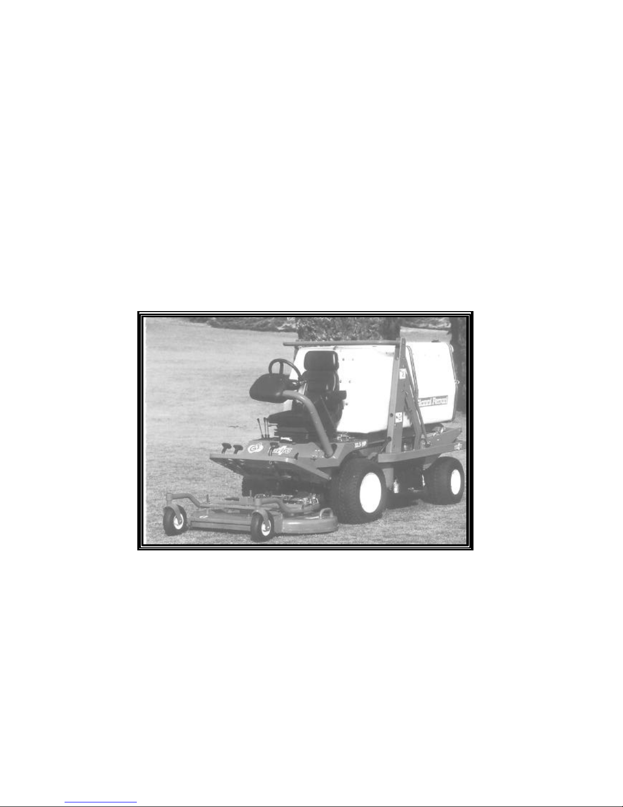
Turbo 1-2-4 is a professional self-propelled mower. This machine has been designed solely for grass cutting and
care in parks and gardens, in the specifications described in this Operator’s Manual.
The operator is responsible for any damage which may occur through improper use and operation outside the
bounds of any instructions given in this manual.
3 – OPERATOR’S RESPONSIBILITIES
- The operator must carefully read this manual and become familiar with the correct way in which to operate,
lubricate and service the machine.
- The operator is responsible for inspecting the machine and must replace or repair those parts subject to continuous
wear which could if neglected cause harm to others.
- The operator is responsible for any harm to third parties, to himself or to property resulting from improper use of
the machine or by failure to comply with the instructions given in this manual.
- The machine has been designed for professional users and should only be used after an adequate training period.
Never allow children or untrained personnel to use the machine. Never carry passengers.
- The operator must not tamper with the machine, or make modifications to it or to any accessories fitted, or fit any
parts or equipment which have not been supplied by our company.
- The machine must only be used for its intended purpose of grass cutting.
- Only use spare parts or accessories which have been designed and supplied by our company for the specific model
in your possession. Please contact your retailer for further information. It is absolutely forbidden to make changes
or to modify the machine other than in the ways expressly indicated in this manual.
The user and the operator are responsible for accidents and hazards caused to other people and to their
goods.
THIS SYMBOL IS USED TO DRAW YOUR ATTENTION TO THE SAFETY PRECAUTIONS
WHICH MUST BE TAKEN BY THE OPERATOR TO AVOID ACCIDENTOR INJURY.
PAY THE UTMOST ATTENTION WHEN YOU SEE THIS SYMBOL: YOUR SAFETY AND THOSE
OF OTHERS WILL BE AT STAKE.
THE OPERATOR MUST COMPLY WITH THE SAFETY INSTRUCTIONS GIVEN IN THIS
MANUAL WHEN USING THE MACHINE.

Operator’s Manual Turbo 1 - 2 - 4
Page 4
©GF Gianni Ferrari 10-2001
4 – SAFETY REGULATIONS
THE PRUDENT OPERATOR IS THE BEST OPERATOR.
Many accidents can be prevented by compliance with the instructions given in this manual. The machine must ONLY
be used by professionally trained operators.
GENERAL INSTRUCTIONS
1) Carefully read all parts of this manual.
2) Before starting work, always inspect all parts of the machine for any malfunction, loose bolts and screws, worn
belts, blades and any other damaged or badly fixed parts. It is absolutely forbidden to use the machine unless it is in a
perfect condition. Always carry out the recommended inspections and maintenance operations before use.
3) Become familiar with all parts and controls of the machine before starting up.
4) Never carry passengers on the machine and never allow children or untrained personnel to use it.
5) Ensure that the operating area of the machine clear of persons (other than the operator). Particularly check that there
are no children, animals or obstructions nearby.
Never allow anyone to stand near the machine while it is working or manoeuvering.
6) Only use genuine parts and accessories supplied by our company and never carry out or permit any modifications or
changes to the machine. Contact your Dealer for information.
7) Ensure that the work area is clear of any object which could damage the machine or cause injury to any person, such
as glass, metal, wood etc.
8) Replace all damaged, illegible or missing safety or warning decals and ensure that they are kept clean and legible.
Check the list of decals in the relative safety section.
9) Only engage the PTO when sitting on the seat having checked for enarby persons and objects.
10) The operator must ensure that his/her hands, feet, clothing and hair are kept away from all moving parts.
11) Never use the machine without first checking that all guards and covers are serviceable and in their correct
positions.
12) If the machine hits or drags up an object, immediately stop it, put on the parking brake, switch off the engine,
remove the key, disengage the PTO, rest the machine on the ground and check all parts. Before restarting check that
conditions have been reset for optimum machine operation.
13) When the machine is not in use, disengage the PTO, lower the attachment allowing it to rest on the ground, switch
off the engine, remove the key and set the parking brake.
14) When moving to another location out of the operating area, disengage the PTO and keep the mower deck or other
attachment as indicated in the paragraph relating to the attachment itself. As for driving on roads, remember to comply
with the rules pertaining to the Country in which you are operating.
15) Never dismount from the machine whilst it is in motion or when the engine is running.
16) Never switch on the engine in a closed place or without adequate ventilation. Exhaust fumes are toxic.
17) Never allow work with flames or sparks to be carried out near the fuel tank or the battery. Leave the engine cooling
before parking the machine in closed places. If you have to empty the tank from fuel, execute this operation outdoor.
18) Never park the machine on a downward slope. If this is necessary for short periods and with the possibility of a
visual control, try to park transversally to the slope and check that the parking brake is engaged. However, follow the
limits that are specified in the next pages.
19) Always use the machine and attachments at a speed compatible with safety requirements.
20) ALWAYS TAKE GREAT CARE WHEN USING THE MACHINE ON SLOPES, ESPECIALLY WHEN
WORKING TRANSVERSALLY TO THE SLOPE.
TURBO 4: ON SLOPES USE THE TRANSMISSION SELCTOR IN «POSITION A» (PERMANENT 4
WHEEL DRIVE – SEE CONTROLS SECTION – TRANSMISSION SELECTOR), IN WHICH THE
MAXIMUM IS OBTAINED. AVOID POSITION C.
REDUCE FORWARD SPEED TO A MINIMUM AND REST THE MOWER DECK AND OTHER
ATTACHMENTS ON THE GROUND, EVEN WHEN TRANSPORTING THE MACHINE TO ANOTHER
LOCATION.
WHEN USING THE MACHINE A WARNING BUZZER WILL SOUND TO INDICATE WHEN THE
MACHINE IS REVERSING, COLLECTOR DUMPING, LIFTING AND DURING HOPPER RAISING
AND LOWERING OPERATIONS. A SAFETY DEVICE WILL PREVENT THE COLLECTOR FROM
BEING DUMPED, RAISED OR LOWERED WHILE THE PTO IS ENGAGED.
IT IS ESSENTIAL TO DISENGAGE THE PTO WHENEVER THE MOWER DECK OR OTHER
ATTACHMENT WITH SPINNING BLADES ARE RAISED.

Operator’s Manual Turbo 1 - 2 - 4
Page 5
©GF Gianni Ferrari 10-2001
THE MAXIMUM SLOPE ON WHICH THE MACHINE MAY BE USED SHALL NOT EXCEED
27% (15°).
AVOID OBSTRUCTIONS AND IRREGULAR GROUND WHICH COULD AFFECT THE STABILITY OF
THE MACHINE.
NEVER USE THE GRASSCATCHER HIGH DUMP ELEVATOR WHEN WORKING ON SLOPES.
21) Always wear suitable clothing when using and servicing the machine: goggles, gloves, shoes and other protective
garments.
22) In conclusion, pay attention to all hidden dangers not expressly mentioned in this manual in order to ensure
both your own safety and that of others.
Safety devices
The machine is equipped with the following safety devices:
The electric horn sounds:
1. when the hand brake is on and the unit is advancing
2. when the coolant temperature is too high
3. by manual operation with pushbutton
4. when the hydraulic oil temperature is too high
The buzzer sounds:
1. when the unit is going in reverse
2. during grasscatcher dumping
3. during grasscatcher lifting
The engine does not start when:
1. the hand brake is not on or when the operator is not seated on the seat
2. the PTO is engaged
3. forward and reverse pedals are not in neutral position
4. the body is open.
The engine turns off:
1. at any time when the operator stands up or takes his/her weight off the seat
2. during grasscatcher dumping or lifting when the PTO is engaged
3. if the body is open
In order to keep the engine running when the unit is stationary and in neutral the PTO must always be disengaged and:
a. either the hand brake shall be engaged,
b. or the operator is on the seat.
- Check the above described function of the electric horn and of the buzzer
- Check the non-starting of the engine in each of the 4 described conditions. It is important for safety that the
test with operator out of place and with absence of hand brake is executed on a level ground and with the
operator standing little up from the seat itself.
- Check the engine switching off in every of the 3 described conditions. It is important for safety that the test
with operator out of place is executed on a level ground and with the operator standing little up from the
seat itself.
THE MACHINE MUST BE REFUELLED IN THE OPEN OR IN A SUFFICIENTLY WELL
VENTILATED PLACE. THE ENGINE MUST BE SWITCHED OFF AND THE AREA MUST BE WELL
CLEAR OF NAKED FLAMES AND SPARKS.
ENSURE THAT DIESEL FUEL IS USED IF MACHINE IS POWERED BY A DIESEL ENGINE.
“The operator can work only if all these devices are operating. He must control their correct
operation at least once a week according to the under reported description”.

Operator’s Manual Turbo 1 - 2 - 4
Page 6
©GF Gianni Ferrari 10-2001
5 – TECHNICAL FEATURES
Hydrostatic transmission with variable displacement pump
- Front axle with piston hydraulic transmission fixed on the differential gear with final drives in oil bath; differential
lock; disc brakes
- Rear axle with piston hydraulic transmission (Turbo 4 only)fixed on the steering differential gear with cascade final
drives in oil bath
Steering and controls
- Steering wheel with hydraulic power steering;
- Forward and reverse with separate pedals;
- Service brake by means of hydraulic transmission; parking and emergency disc brake controlled by pedal.
- Turbo 4: service brake by means of hydraulic transmission; parking and emergency disc brake controlled by pedal.
- Turbo 2 and Turbo 1: service disc brake on the front wheels controlled by independent pedal.
PTO
- Manual engagement with belt tensioning system;
- Transmission with quick coupling telescopic cardan shaft;
- Automatic safety braking on shaft rotation on disengagement;
- Rotation speed: 2900 rpm.
Front attachment coupling
- 2 arms with 2 cylinder hydraulic lifting system.
Grass collection
- Central intake of cut grass by means of a turbine.
Electrical system
- 12 V 75 Amp battery.
- Electric starter, hour meter
- Safety microswitches
- Grass distributor control motor
- Warning buzzer to indicate full load, reverse motion, elevator operation and collector dumping
OPTIONS
- 1.000 litres capacity, hydraulically lifted grasscatcher (700 litres for Turbo1). Rear automatic opening during
grasscatcher dumping. Internal grass distributor, movable by electrical control. Full load warning buzzer.
- Hydraulic grasscatcher elevator discharging up to 210 cm.
- Lighting set
ACCESSORIES
- 130 or 150 cm. mower deck– Central discharge For grass collection.
Mechanical gear box in oil bath.
2 disks with 8 articulated impact-proof blades.
130 or 150 cm. cutting width.
Cutting height adjustable from 2 to 9 cm.
Dumping device for cleaning and maintenance operations.
- 130 cm. mower deck– Side discharge As above with cut grass side discharge.
-160 cm. mower deck-Rear discharge w/o pick-up As above with cut grass rear discharge, 3 disks with 12 articulated
impact-proof blades. 160cm cutting width
- 150 cm. snow blade 150 cm. working width with hydraulic positioning.
- 100 cm. aerator With bladed rotor. Working width 100 cm.
Operator’s Manual Turbo 1 - 2 - 4
Page 7
©GF Gianni Ferrari 10-2001
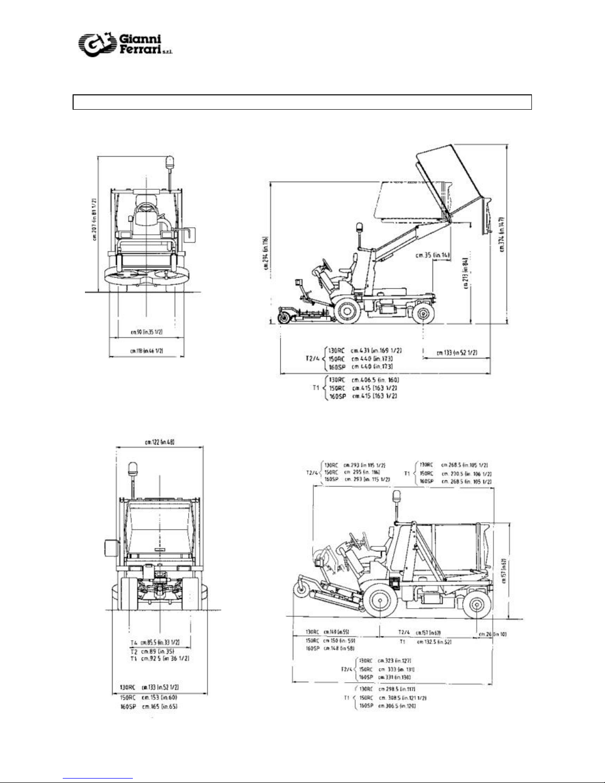
6 - DIMENSIONS
Operator’s Manual Turbo 1 -2 - 4
Page .
©GF Gianni Ferrari 10-2001
8
7 - TRANSPORT
The following operation must be executed with engine switched off.
Lifting must be carried out by fixing
suitable slings in three positions (2 in the
front side of the machine, see picture on the
left; 1 on the rear side, see picture on the
right).
The machine may be transported either
unpackaged or palletized and wrapped in
heat-shrunk polyethylene. It must be firmly
fixed and fastened to the transporter loading
platform.
It is also necessary to ensure that the parking brake is engaged and all wheels are chocked.
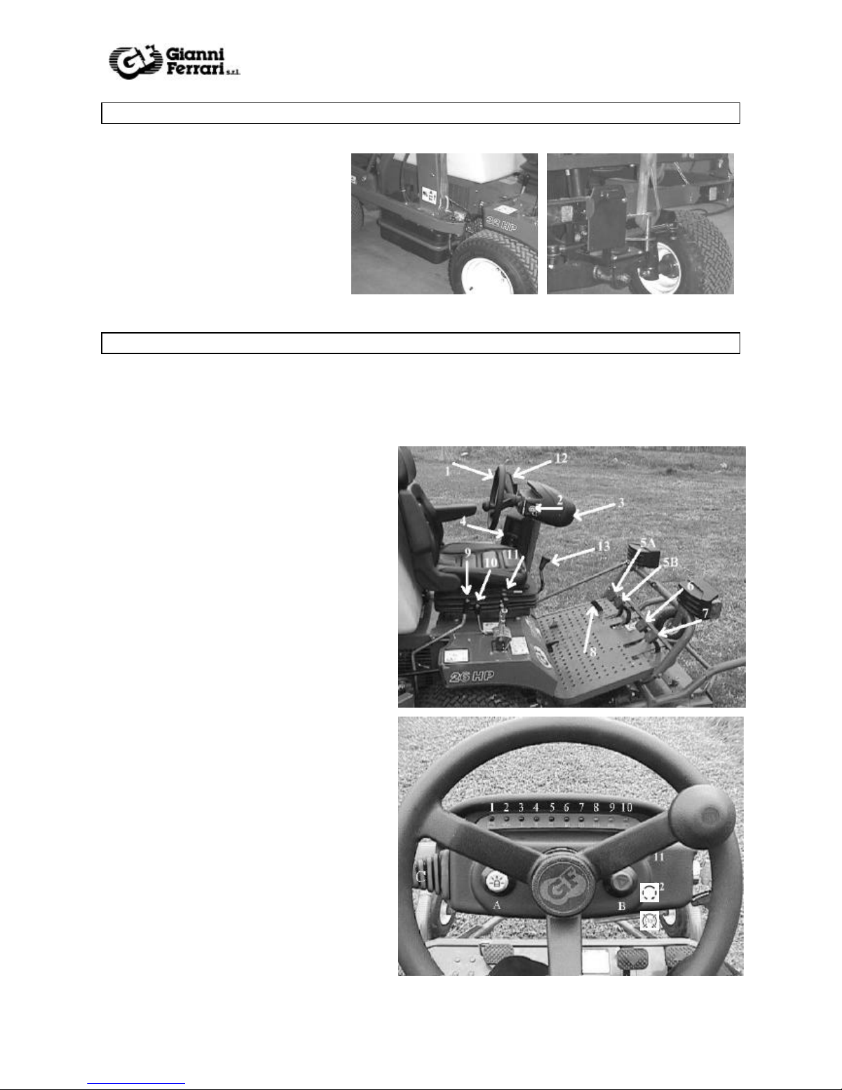
8 – CONTROLS AND INSTRUMENTS
IN EMERGENCY CONDITION:
To stop every movement turn the counter clockwise
For blades and turbine movements release the PTO lever.
To stop other movements it is enough leaving the driving control that will return to the neutral position.
As it concerns the emergency braking please see chapter 5.
1 Steering wheel
2 Starter key
3 Central control panel (see following pictures)
4 Side control panel (see following pictures)
5A Parking brake pedal
5B Brake pedal (Turbo 2 only – equipped with
lighting set)
6 Reverse pedal
7 Forward pedal
8 Differential lock
9 PTO engagement lever
10 Throttle lever
11 Hydraulic controls levers (see chapter 10).
12 Mirror (supplied only when the lighting set is
equipped)
13 Speed selection lever (Turbo2 only)
Central control panel
1 Battery alternator
2 Oil pressure
3 Coolant max temperature
4 Oil filter clogging
5 Glow plugs preheating
6 Fuel stock
7
8 Direction indicator
9 Side light (*)
10 Lower beams (*)
11 Start
12 Stop
 Loading...