

Page 1
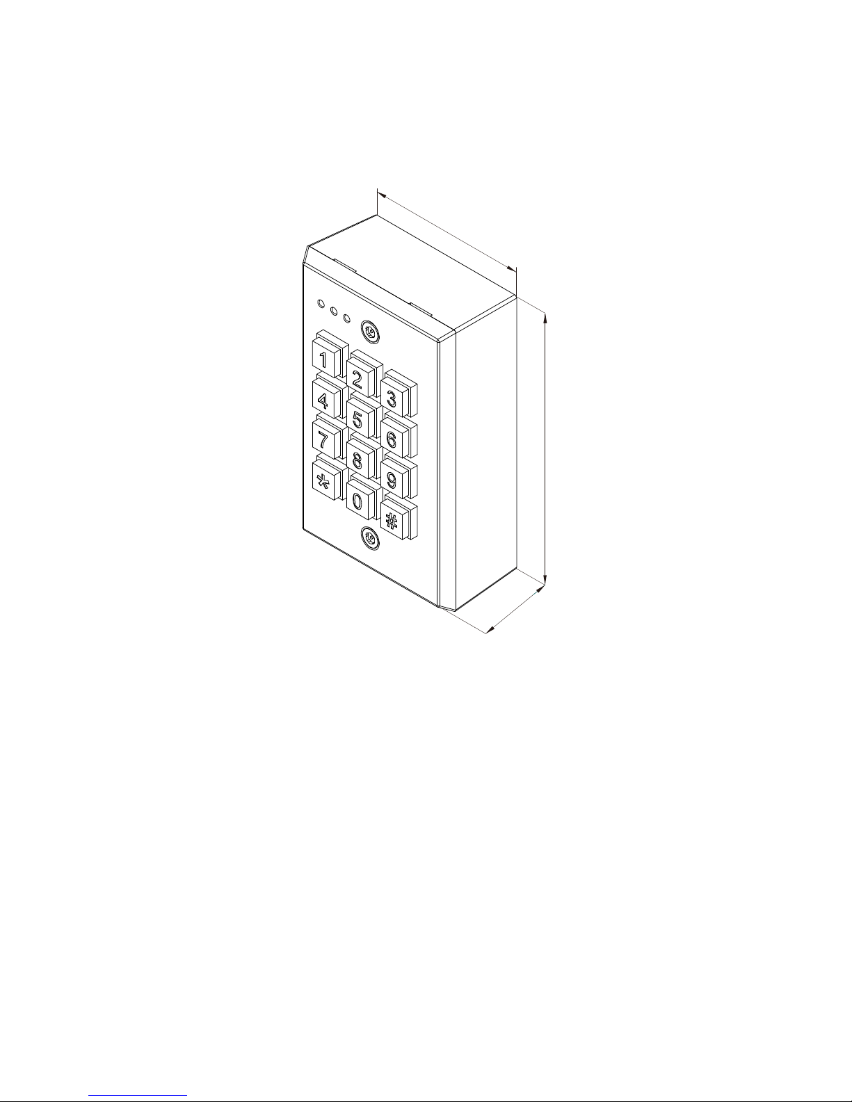
DG-20 Digital Keypad
Operation Manual
114
6
9
.
5
3
5
.
3
Unit: mm
I.Features:
1. Allows up to 99 access PINs.
2. 3 LED indicators & buzzer for status indication . Keypad with beep sound.
3.
Maximum 20-digit-code password anti-trailing design or lockout for 30 seconds after
entering 5 times invalid PINs (The keypad without beep sound during the period time).
4. Non-volatile memory due to power failure.
5. Built-in tamper switch.
6. AUX signal outputs : In-built additional outputs for contact with other access control
devices.
II. Specifications:
Copyright All Rights Reserved.
P-MU-D
G-20 Ver. A Publish: 2010.06.28 Page: - 1 -/ 5
Page 2
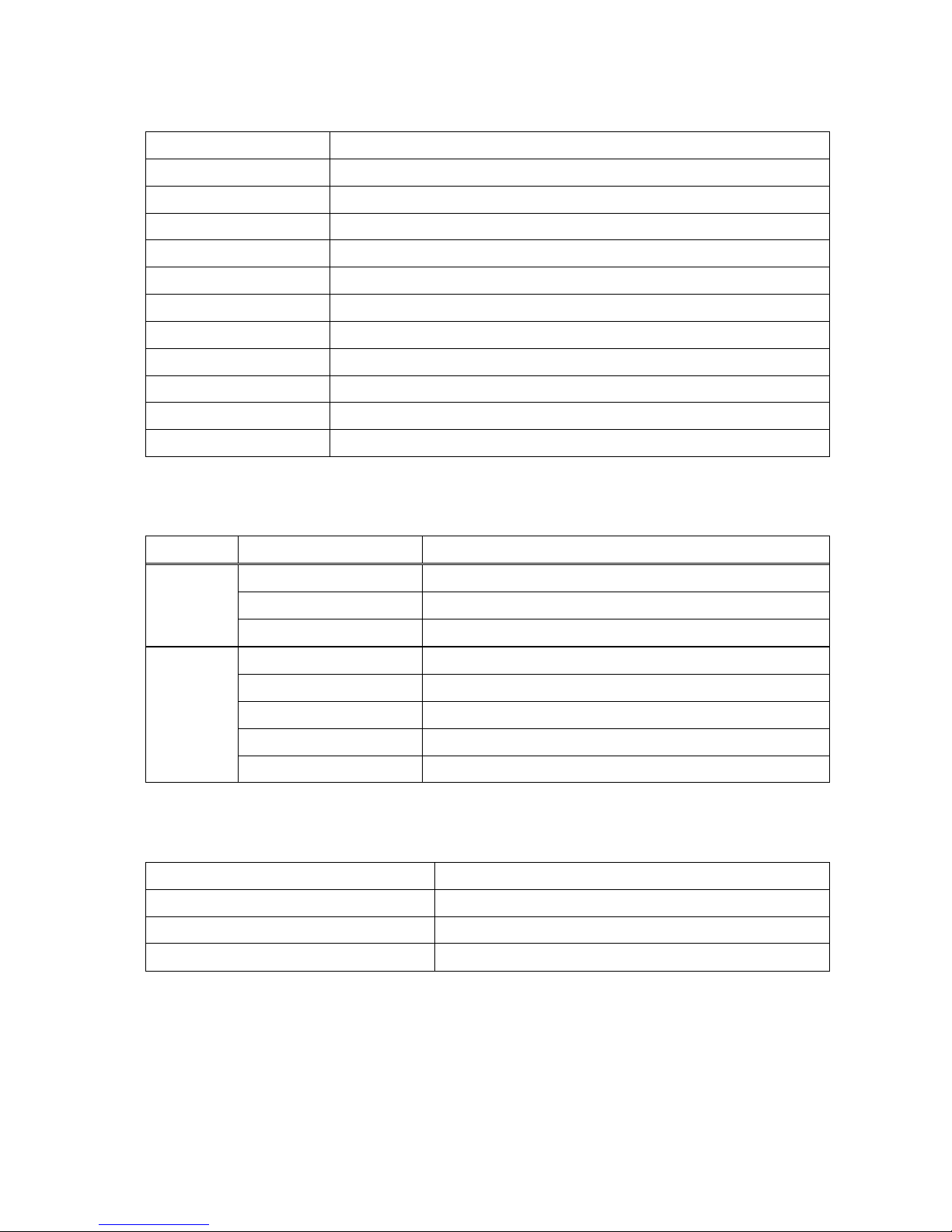
Operating Voltage 12VDC/AC
Current Draw
Holding: 50mA/12VDCćPull-in: 130 mA/12VDC
Keypad
4X3 matrix 12-digit (0~9-Ŏ,#)
Input 1 contact for Request-To-Exit button
Output 1 relay (N.O./N.C./Com. Dry contacts)
Optional PIN length 4~8 digit (master code & PINs must be same length)
Relay Electric Rating Max.12A/14VDC
Memory Volume 99 PINs
Relay Strike Time 01~99 seconds , Toggle mode (00)
LED Status Indication 3 LED indicators display (Red & Yellow/ Green / Yellow)
Ambient Humidity 5%~95% (Non-condensing)
Operating Temperature -20°C~+70°C
III. Status Indication & Default Setting Parameters:
Mode Status
Green Relay active
Yellow AUX Output active
LED
Red Normal (Power On)
1 Short Beep Key in
1 Long Beep Valid PINs
3 Beeps (Da,Da,Da) Enter programming mode, completed setting
1Long Beep (Da) Incorrect input
Beep
1 Longer Beep Reset
IV. Factory Default Setting:
Master Code 1234 (4 digit)
Relay Strike Time (Time Delay Setting) 5 seconds
Pressed Key Time Delay 60 seconds (Fixed)
Programming Mode Time Delay 90 seconds (Fixed)
Copyright All Rights Reserved.
P-MU-D
G-20 Ver. A Publish: 2010.06.28 Page: - 2 -/ 5
Page 3

V. Operation Instruction:
1. Enter programming mode:
Press the master code twice 1234 1234 to enter programming mode (1 beep, yellow
LED on).
2. Exit programming mode:
Press # , back to stand by mode (Red LED on).
3. Change Master Code(default 4-digitĂ1234)
1. Enter programming mode
2. Press*00
3. Select length of digit and reset PINs (4 digit ~ 8 digit)
4. Exit programming mode.
(All setting must contain same length of digit with the master PINs).
4. Adding / Change Master Code
a.
1. Enter programming mode
2. Press*(01~19)
3. (4 digit ~ 8 digit)
4. Exit programming mode.
b.
1.Enter programming mode
2.PressŎ6(20~99)
3. (4 digit ~ 8 digit)
4. Exit programming mode
5. Clear user's PINs
1. Clear individual user's PINs : Enter programming mode, press *50 - (01~99),
exit programming mode.
2. Clear all users' PINs : Enter programming mode, press *50 - 00, exit programming
mode.
6.
Enter Relay programming mode (default : 5 seconds)
(Press 00 to Toggle mode, Press 05 = 5 seconds, etc.)
Enter programming mode, press *20 - (00~99), exit programming mode.
7. Keypad Lockout Function (default : cancel)
Enter keypad lockout function : Enter programming mode, press *51, exit programming
mode. (Repeat the setting once = cancel the function).
8. Change programming mode (default : 0)
1. 20 PINs mode : Enter programming mode, press *53 - 0, exit programming mode.
(Press upto 20 PINs and will lockout 30 seconds in the absence of valid PINs).
Copyright All Rights Reserved.
P-MU-D
G-20 Ver. A Publish: 2010.06.28 Page: - 3 -/ 5
Page 4

2. Individual PINs set : Enter programming mode, press *53 - 0, exit programming mode.
(Alarm sound for any invalid PINs, or lockout 30 seconds in case of continue 5 sets of
invalid PINs).
9. Change operation mode (default : 0)
1. Ordinary mode : Enter programming mode, press *52 - 0, exit programming mode.
2. Bypass mode : Enter programming mode, press *52 - 1, exit programming mode.
(Bypass mode equal to Toggle mode)
10. Adding Bypass mode PINs
Enter programming mode, press *54 - (4 digit ~ 8 digit), exit programming mode.
11. AUX Output mode (default : 7)
1. Cancel AUX function : Enter programming mode, press *57 - 0, exit programming
mode.
2. Invalid PINs output signal : Enter programming mode, press *57 - 2, exit programming
mode
.
3. Bell sound for * key : Enter programming mode, press *57 - 3, exit programming mode.
4. Contact push-button output signal : Enter programming mode, press *57 - 6, exit
programming mode.
5. Set AUX PINs as output signal : Enter programming mode, press *57 - 7, exit
programming mode. (e.g. Be compelled or for emergency purpose)
12. AUX
output time delay (default : 000)
ĞPress 000 = toggle mode, press 005 = 5 seconds, etc.ğ
Enter programming mode, press *58 - (000~999), exit programming mode.
(When apply 11-2 and 11-3 can not allow 000 for time delay setting).
13. Adding AUX output PINs
Enter programming mode, press *40 - (4 digit ~ 8 digit) - exit programming mode.
Copyright All Rights Reserved.
P-MU-D
G-20 Ver. A Publish: 2010.06.28 Page: - 4 -/ 5
Page 5
Copyright All Rights Reserved.
P-MU-DG-20 Ver. A Publish: 2010.06.28 Page: - 5 -/ 5
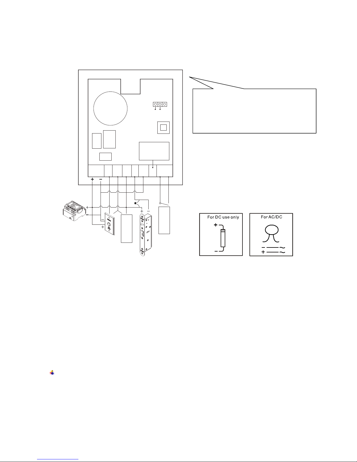
IV. Wiring Diagram:
System
Restore
Output signal
Tamper switch
AUX
Relay
N.O:20A
N.C:12A 14VDC
7A 120VAC
12V
DC/AC
P.B
COM AUX
NC
COM NO Tamper
F
ai
l
-
s
a
f
e
Drawing indicated connecting locks must be
“Fail-safe” version. Please connect negative
wire of the lock to N.O. contact if applying
“Fail-secure” locks to avoid damage.
NoteĈ
1. Recommend to apply single voltage power supply unit and beware of AC or DC version of the
connecting locks.
2. It is suggested to use # 22~26 AWG insulation wire.
3. Exit button is at N.O. contact.
4. With CE qualification EMC specification.
5. The door locks or relay must have a varistor or a diode across the door locks terminals to sup press the
back EMF of the locks-failure to do so will damage the relay contacts and electronic components , or
even burns the controller.
Warranty:
The product is warranted against defects in material and workmanship while used in normal service for a
period of 1 year from the date of sale to the original customer. The GEM policy is one of continual
development and improvement ; therefore GEM reserves the right to change specifications without notice.
 Loading...