

Page 1
5D000XX/F
FT-M1211A
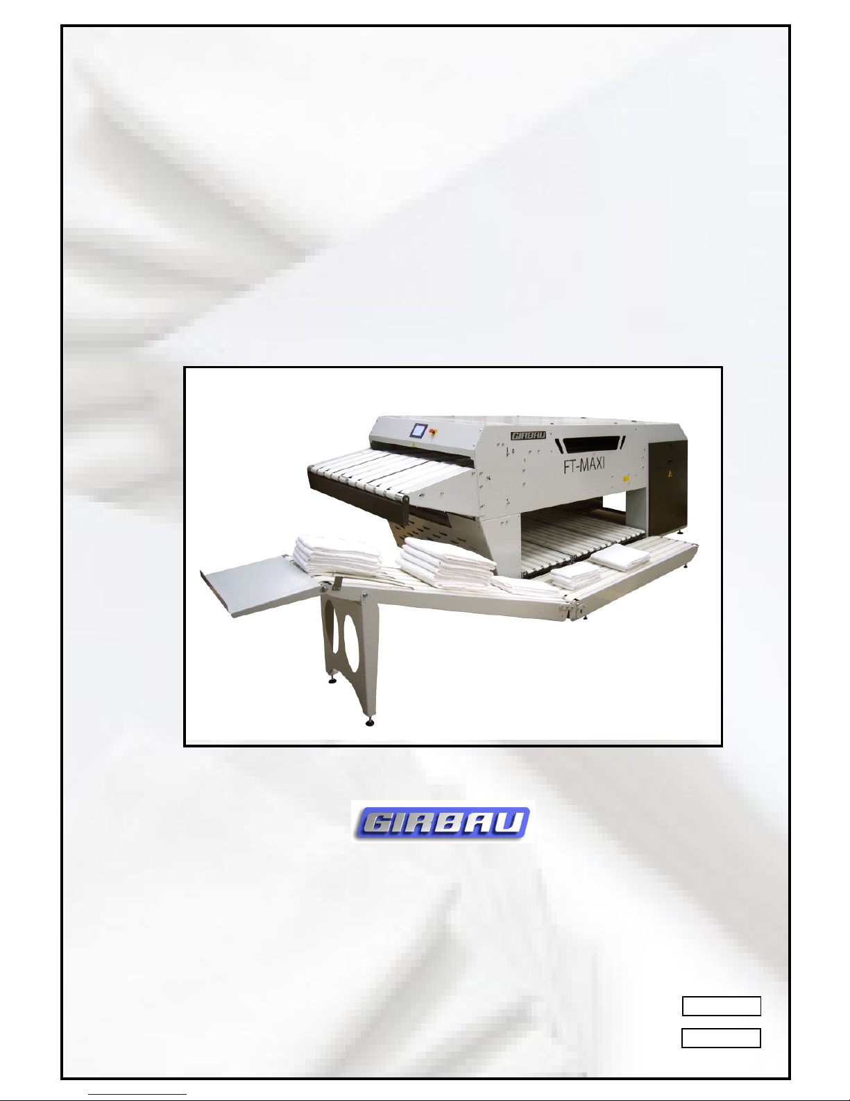
FT-MAXI
FOLDER
GIRBAU , SA
Crta de Manlleu, km.1
08500 VIC (Barcelona) .SP AIN
Tel. 34 93 8861 100
Fax 34 93 8860785
[email protected]
www.girbau.com
USA et CANADA :
CONTINENT AL GIRBAU Inc.
2500 St ate Road 44
WI 54904 Oshkosh .USA
Tel. 34 93 8861100 1(920) 231-8222
Fax 1(920) 231-4666
info @continentalgirbau.com
www.continentalgirbau.com
Page 2

Modele Series
FT-MAXI From PLP243
Page 3

3 FT-M1211A
TECHNICAL MANUAL
1st part Generalities, Installation, Fonctioning
2nd part separate Electrical and pneumatic schemas
3rd part separate Automation
Translation of the original note
Page 4

FT-M1211A 4
TABLE OF CONTENTS
CE DECLARA TION OF CONFORMITY.................................................................................................6
1 PRESENT ATION...............................................................................................................................7
1.1 Conditions of use ....................................................................................................................7
1.2 Generalities ............................................................................................................................. 7
1.3 Warnings................................................................................................................................. 8
1.4 Functioning pictograms......................................................................................................... 10
1.5 Technical characteristics ...................................................................................................... 11
2 HANDLING AND INST ALLA TION ..................................................................................................... 20
2.1 Handling ................................................................................................................................ 20
2.2 Installation ............................................................................................................................. 21
2.3 Connecting to electrical and pneumatic supplies..................................................................21
2.4 T esting...................................................................................................................................23
2.4.1 Check of the sense of rotation of motors .....................................................................23
3 SAFETY .......................................................................................................................................... 24
3.1 Generalities ........................................................................................................................... 24
3.2 Stopping the machine............................................................................................................ 24
3.3 Intervention during operation ................................................................................................. 25
4 PRINCIPLES AND FUNCTIONING..................................................................................................26
4.1 Principles .............................................................................................................................. 26
4.2 Functioning............................................................................................................................27
5 MAINTENANCE OPERATIONS.......................................................................................................29
5.1 General maintenance............................................................................................................29
5.2 Servicing of the filter / Regulator ........................................................................................... 31
6 SPARE PARTS ............................................................................................................................... 36
6.1 Basic emergency kit - FT-MAXI -2011-06 .............................................................................. 36
6.2 Maintenance kit - FT-MAXI -201 1-06...................................................................................... 36
6.3 Annual preventive kit of maintenance - FT -MAXI -201 1-06..................................................... 36
6.4 Maintenance kit - L5 - L6 - L7 - FT -MAXI -201 1-02................................................................ 36
6.5 Maintenance kit - M5 - FT-MAXI -201 1-02..............................................................................37
6.5 Maintenance kit - M5 - FT-MAXI -201 1-02..............................................................................37
6.6 Maintenance kit - M6 - FT-MAXI -201 1-02..............................................................................37
6.7 Maintenance kit - Q5 - FT -MAXI -2011-02.............................................................................. 37
6.8 Maintenance kit - Q6 - FT -MAXI -2011-02.............................................................................. 37
6.9 Maintenance kit - Q7 - Q8 - Q9 - FT -MAXI -201 1-02.............................................................. 37
7 EXPLODED VIEWS........................................................................................................................41
4M05675 Feeding table ............................................................................................................. 43
4M05635 Straps - Feeding t able ............................................................................................... 43
4M05632 Feeding table .............................................................................................................. 45
09-0031 Kit.................................................................................................................................47
4M05674 Frame.........................................................................................................................49
4M05616 Folding table ............................................................................................................... 51
4M05622 Central table ............................................................................................................... 53
4M05975 Template ..................................................................................................................... 55
4M05681 St acker flap................................................................................................................ 57
4M05954 Belt guide feeding table..............................................................................................59
4M05698 Cross module meca.................................................................................................. 61
4M05613 Belt guide FT-MAXI ....................................................................................................63
4M05699 Cross module straps.................................................................................................. 65
4M05619 Tubulure of blowing LG985......................................................................................... 67
4M05633 Cross module motor ..................................................................................................69
4M05637 Liaison cross + Fold con + Feed con........................................................................71
4M05640 Casing .......................................................................................................................73
Page 5

5 FT-M1211A
09-0145 B (part 2) Kit................................................................................................................. 75
09-0147 A - 09-0165 A Kit..........................................................................................................77
09-0148 A Kit .............................................................................................................................79
09-0124F Kit .............................................................................................................................81
4M05631 Shuttle LU450 ............................................................................................................ 83
4M05646 Shuttle LU450 - Straps ...............................................................................................83
4M05644 Shuttle LU450 - Kit 09-0146A ....................................................................................83
4M05601 Shuttle LU615 ............................................................................................................ 85
4M05636 Shuttle LU615 - Straps............................................................................................... 85
4M05644 Shuttle LU450 - Kit 09-0146A ....................................................................................85
4M05923 Unidirectional roller LU=600....................................................................................... 87
4M05924 Unidirectional roller LU=530....................................................................................... 87
4M05925 Unidirectional roller LU=435....................................................................................... 89
4M05926 Unidirectional roller LU=365....................................................................................... 89
4M05947 Discharge conveyor ..................................................................................................91
4M05634 Discharge conveyor ..................................................................................................91
4M05977 Storage tray options....................................................................................................93
4M05749 Conveyor with free rolls option ...................................................................................95
Page 6

FT-M1211A 6
CE DECLARATION OF CONFORMITY
Page 7

7 FT-M1211A
1 PRESENTATION
1.1 GENERAL PRECAUTIONS
Conditions of use :
It is IMPERITIVE that before any person begins to work with this machine or provides
for its maintenance ( commissioning, maintenance, dismantling...), thoroughly reads and
respects the entirety of the instructions contained within this manual, as well as those concerning
the controls sections ( electric and pneumatic schemas).
Those individuals that will be responsible for the maintenance of this machine are to
be properly trained and qualified to do so
GIRBAU machines have been conceived while keeping in mind the aim of limiting potential
risks to personnel, given the current technologies available. It is therefore absolutely forbidden
to attempt any maneuver or intervention whatsoever that has not been intended for in the
normal usage of the machine and notably to attempt to reach into the machine without
previously ensuring that it has been completely stopped ( see Chapter 3 Safety) or to modify
a cycle or one of its protective coverings.
The machines must be powered by an electrical supply that meets all current norms
and maintained in good condition following maintenance instructions.
Note : The machine’s identification plate is located on the lower left side in the back of the
machine.
1.2 GENERALITIES
This machine has been especially created for the folding of dry bath towels.
Any other utilization is strictly forbidden and is not considered to be in any case as ‘normal
usage’ of the machine.
However, dry and ironed articles can be p assed through the machine.
The machine is delivered with the feet attached, though they are adjustable. One of the
sides of the machine can be placed against a wall so as to save space.
Plan a space behind and above the machine to open completely the back cover .
The covers that are equipped with safety latches must be put back in place before operating the machine.
The first and second longitudinal folds are made by jets of air . The cross folds are made by
the means of an inversion conveyor belt combined with a jet of air. All of the folds can be
set and modiffied with the aid of the touch screen.
All of the towels can be stacked. The number of articles per stack can be set between 1 to
20. The maximum height of the stack is 250 mm.
The stacks can be discharged on the sides of the machine onto a discharge conveyor .
The moveable guards that are equipped with safety sensors will provoke the immediate
stoppage of the machine once they are opened and will prevent the restarting of the machine
until they are closed and or put back into place (folding table protection grill, cross access
door).
Page 8
FT-M1211A 8
Do not try to remedy a jamming of the machine while the machine is running, which
could lead to serious injuries.
Place the main switch to the OFF position before any intervention on the machine.
Do not turn on the machine until the problem has been resolved. Otherwise, damage
to the mechanical .and electrical components could result.
Incorrect settings that provoke jamming will lead to the damaging of the machine.
Jamming which is accompanied by a loud noise or a grinding sound could be caused
by a problem with one or more of the machine’s components.
Stop the machine to prevent further damage and call a qualified person.
Note : The more centered the article is the better the quality of the fold
The Jean Michel Company declines all responsibility for material and or other damages
resulting from the usage of the machine outside of that which it was designed and intended
for or in the case in which the instructions outlined in the technical manuals have not been
followed.
1.3 WARNINGS
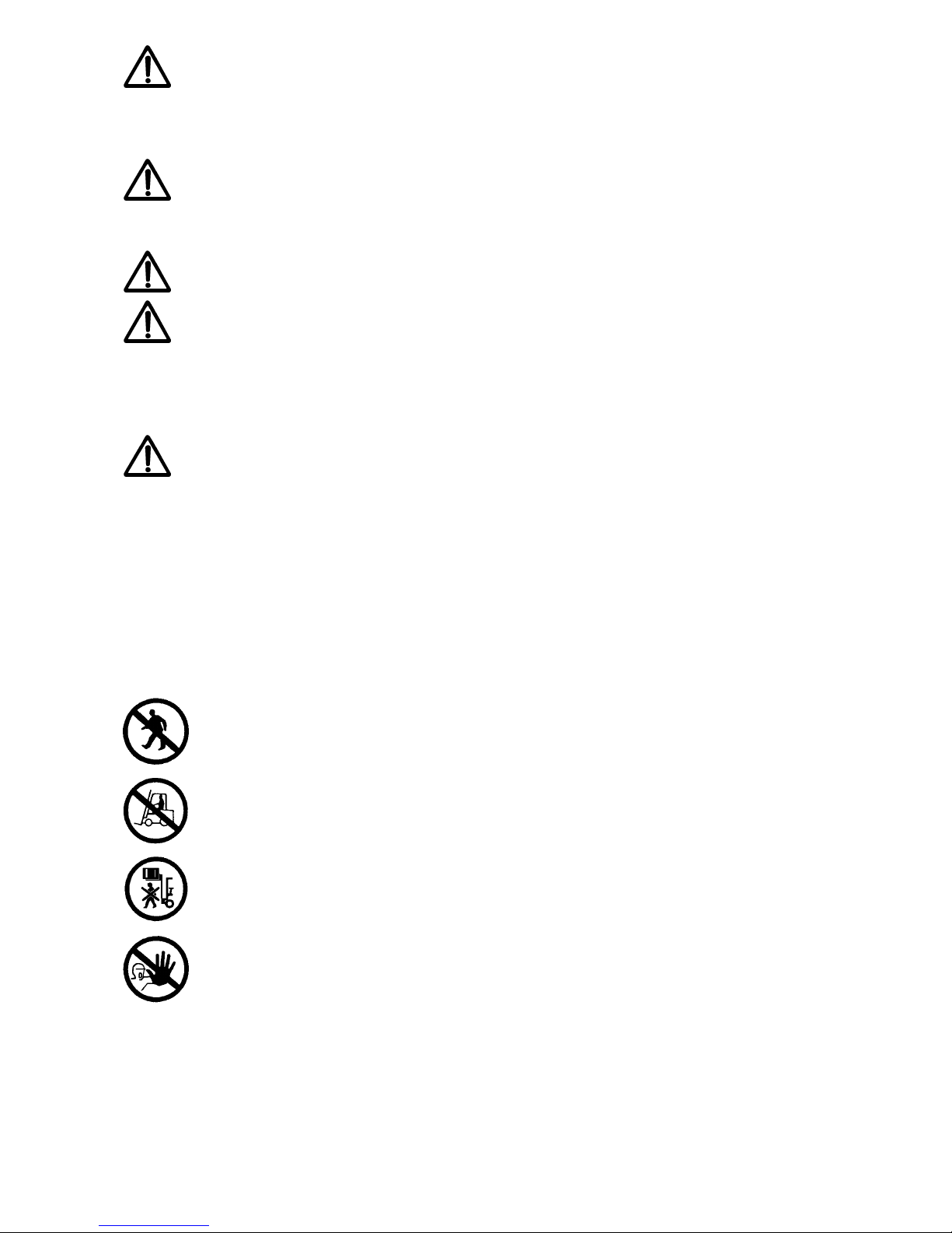
Forbidden pictograms (Red and white circle) :
Entering forbidden
Use of forklift forbidden
Do not stay under load
Access forbidden for unauthorized persons
Page 9
9 FT-M1211A
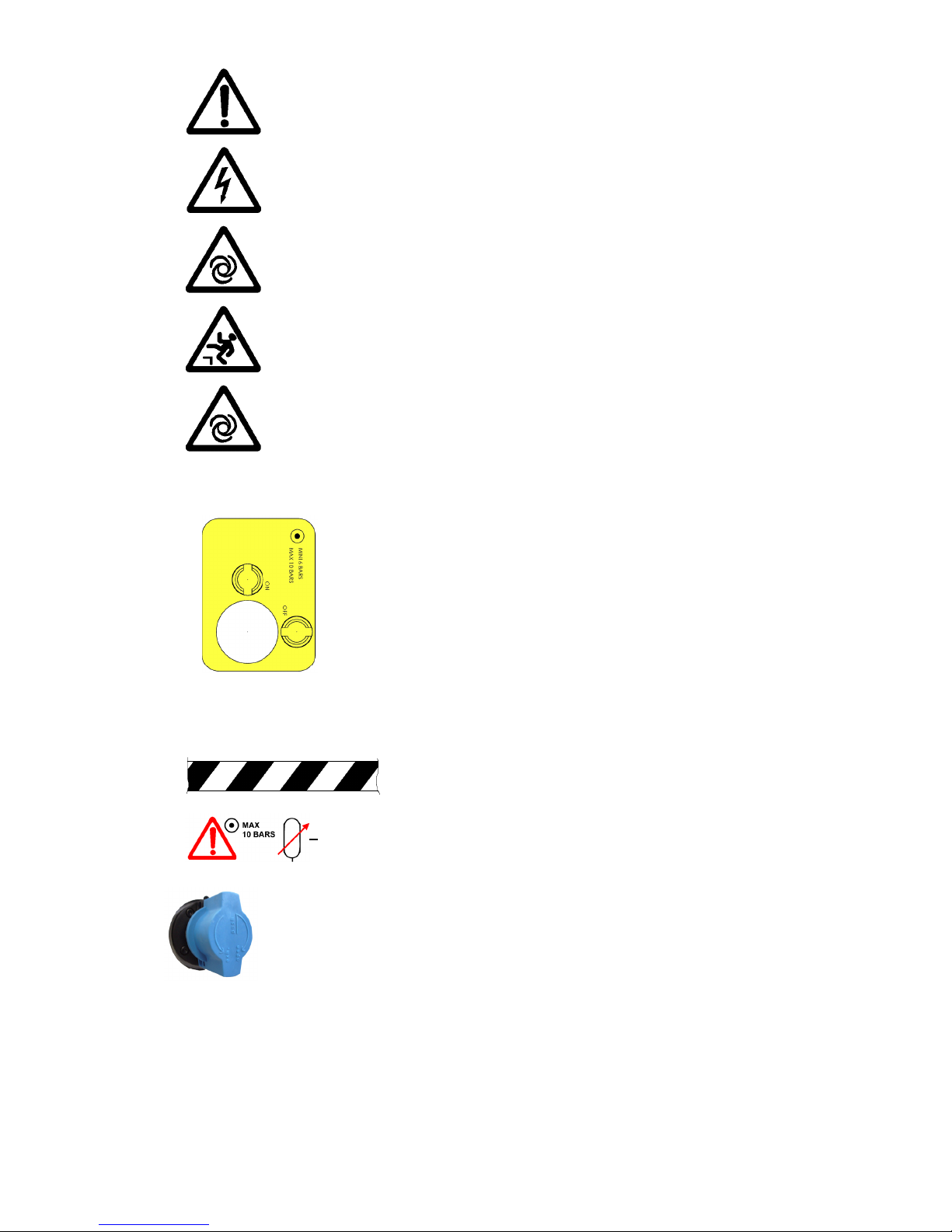
DANGER pictograms (yellow and black triangles) :
General danger
Electrical danger
Mechanical danger
Danger of falling
Mechanical operations
Pneumatic padlockable power
DANGER zone (yellow and black band)
Air suppy
Air supply valve- padlockable
Page 10
FT-M1211A 10
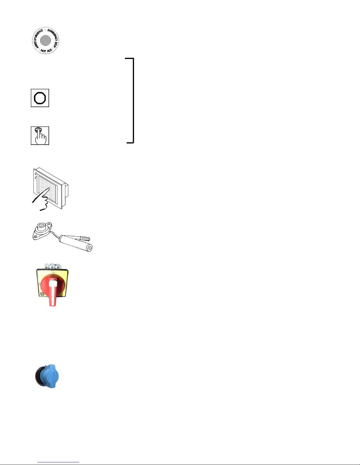
1.4 FUNCTION PICTOGRAMS
Emergency stop
Main On/ Off switch
Stop
Reset
Use touch screen
Lubricate with a grease gun
Turn the selector to ON
These pictograms are found on the touch screen
Turn the selector to OFF and p adlock ( lock not supplied)
Open the air supply valve
Close the air supply valve and padlock ( lock not supplied)
Page 11
11 FT-M1211A
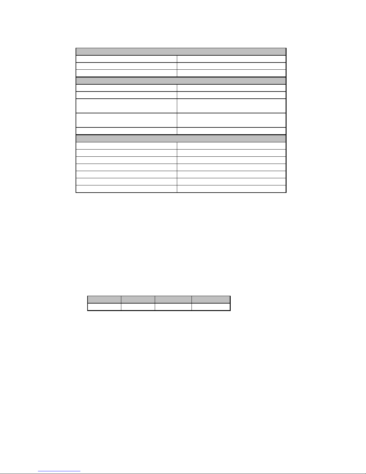
1.5 CARACTERISTIQUES TECHNIQUES
Paint
- T ype : 2 components
- Color : RAL 7035 Light grey
RAL 7022 Dark grey
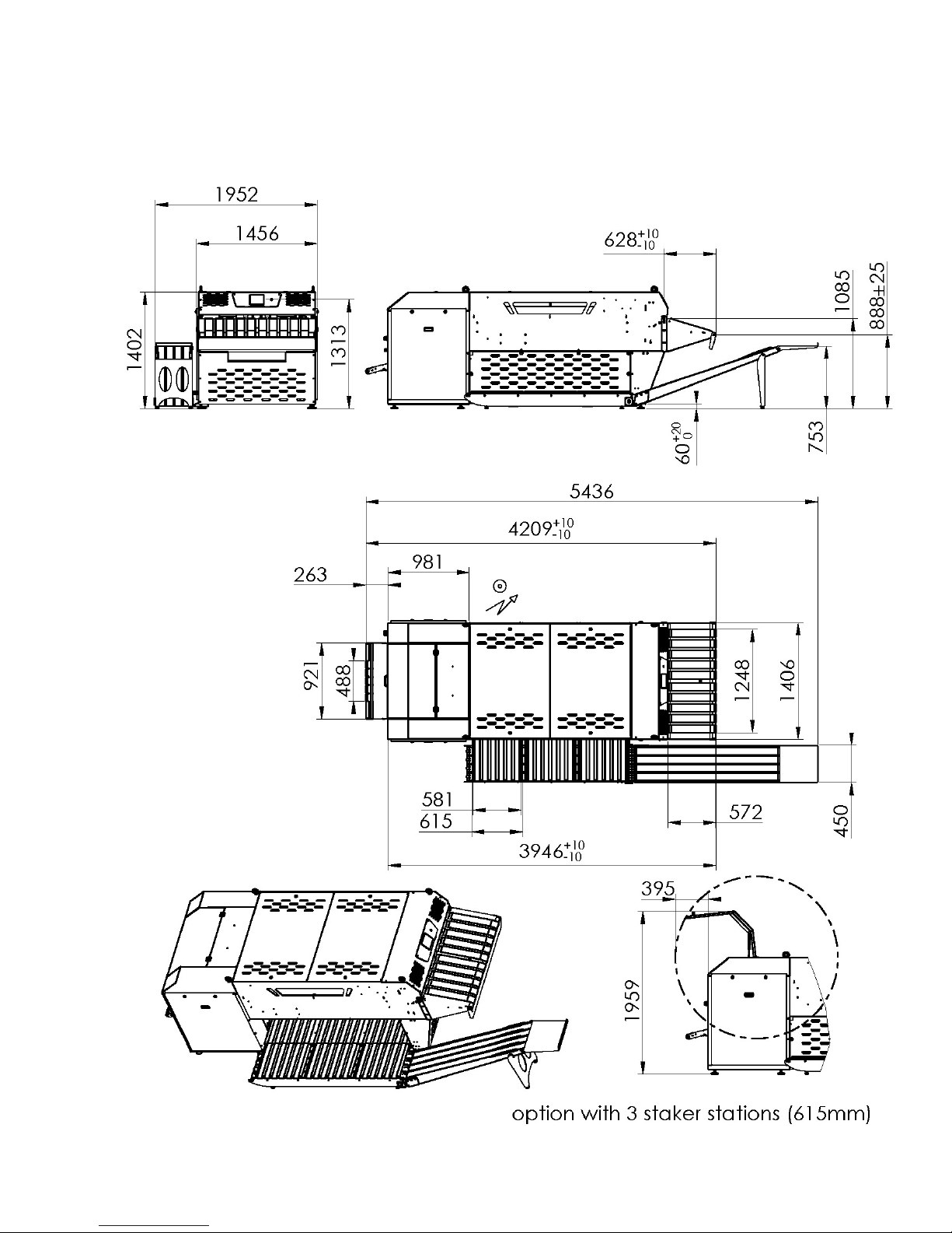
Transport dimensions.
Packaging.
The standard packaging for the machine is cellophane.
If the machine is sent by sea, foresee the use of a box pallet.
Installed power 2,5 KVA
Ga ug e in 230v tri 3 X 4m m ²+ g o ru n d
Ga ug e in 400v tri 3 X 2, 5m m²+gr ound
Maximum air pressure 10 bars
Air supply hose di ame te r Ø15x21
Minimum air pressure
6 bars avec baisse de pre ssi on
tempora i re de 0,5 ba rs maxi
Consumptio n for 100 p i ece s
1-2Nm3/100p
170-335l/100p at 6 bars
Pn euma tic safety P r essostat Set at 4. 8 b ars
Sound le vel a t 1 me te r 75 dbA
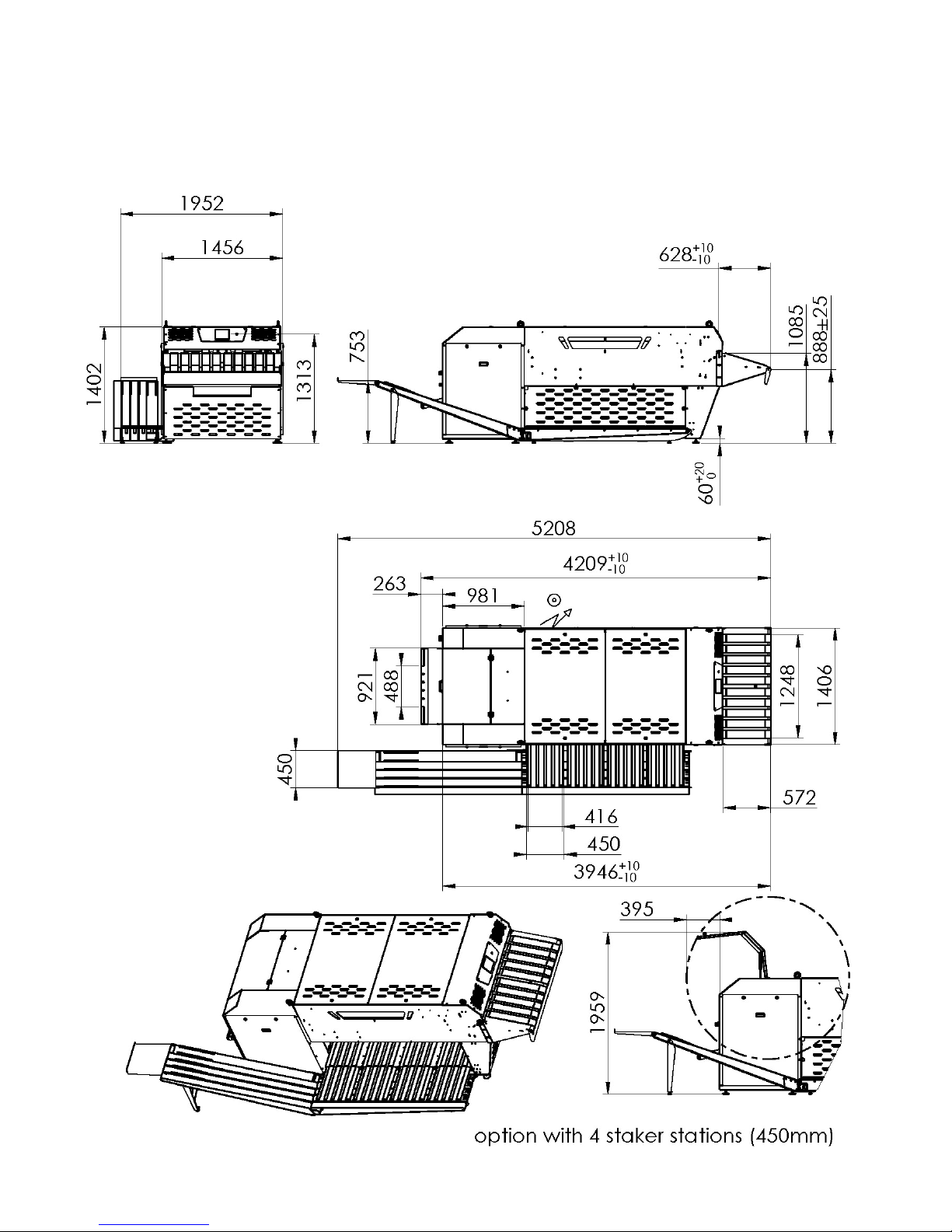
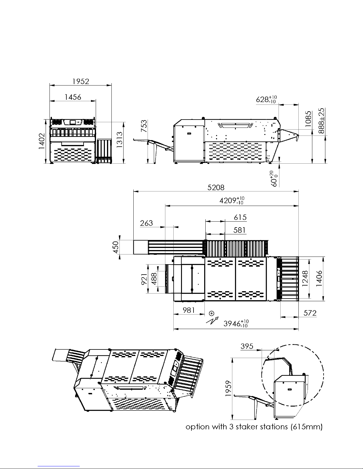
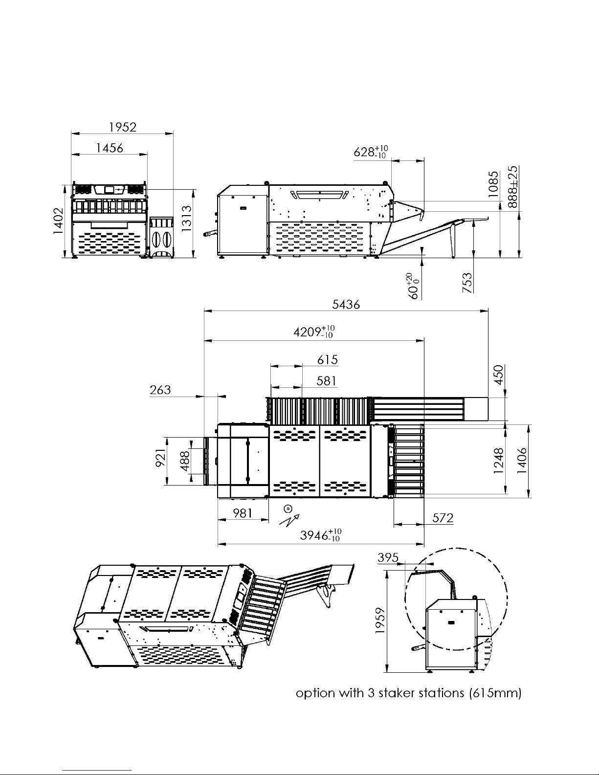
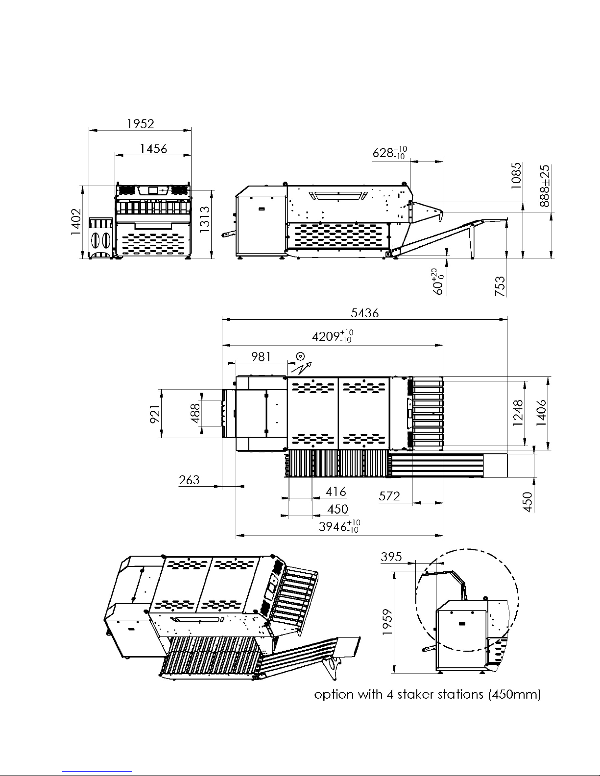
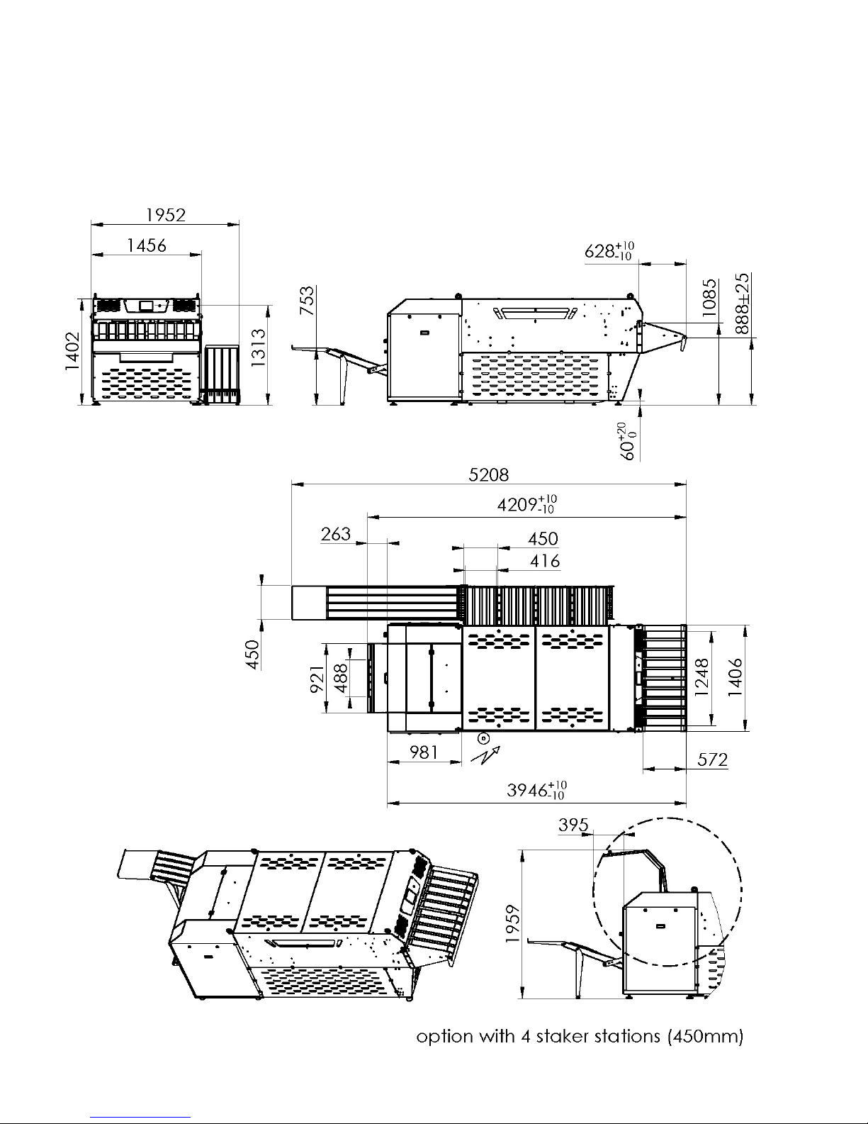
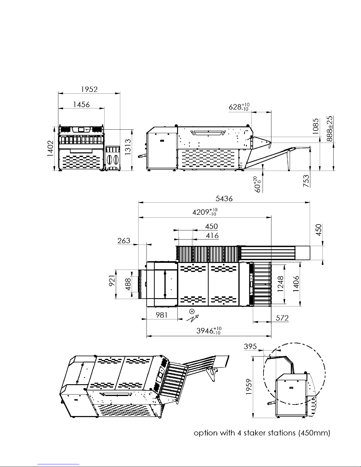
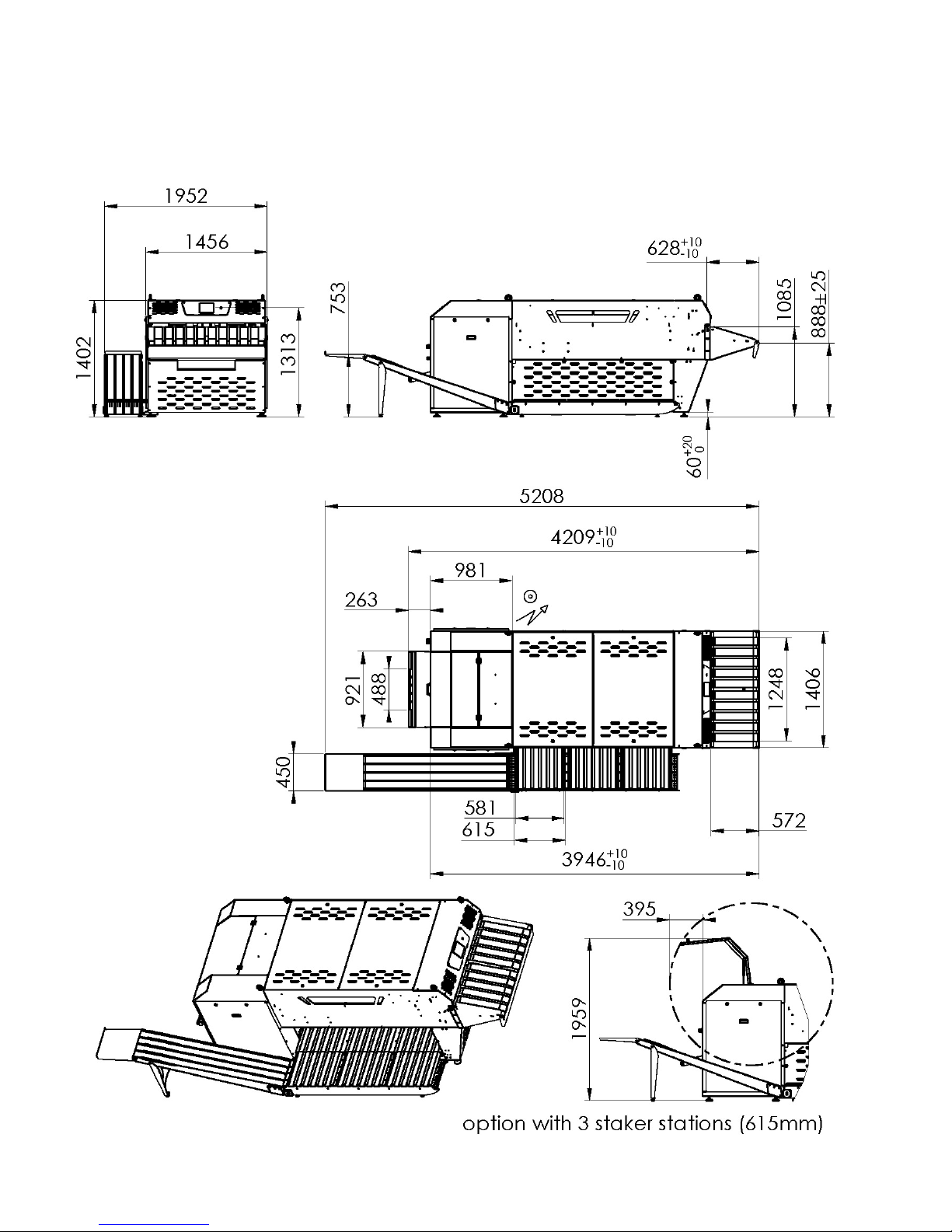
Hei g h t (standard) 1410 mm
Length 3950+10 mm
Use abl e width (Uw) 1952 mm
Wei gh t 1100 kg
Operating temperature range 5°C to 45°C
Humidity 95% à 25% wi thout condensation
ELECTRICITY
COMPRESSED AIR
OTHER CHARA CT ERI STICS
Length (mm) Width (mm) Height (mm) Weight (kg)
4495 1800 2000 1200
Page 12
FT-M1211A 12
IM03019 - C
Page 13
13 FT-M1211A
IM03064 - C
Page 14
FT-M1211A 14
IM03065 - C
Page 15
15 FT-M1211A
IM03066 - C
Page 16
FT-M1211A 16
IM03151 - C
Page 17
17 FT-M1211A
IM03152 - C
Page 18
FT-M1211A 18
IM03153 - C
Page 19
19 FT-M1211A
IM03154 - C
Page 20
FT-M1211A 20
2 HANDLING AND INSTALLATION
2.1 HANDLING
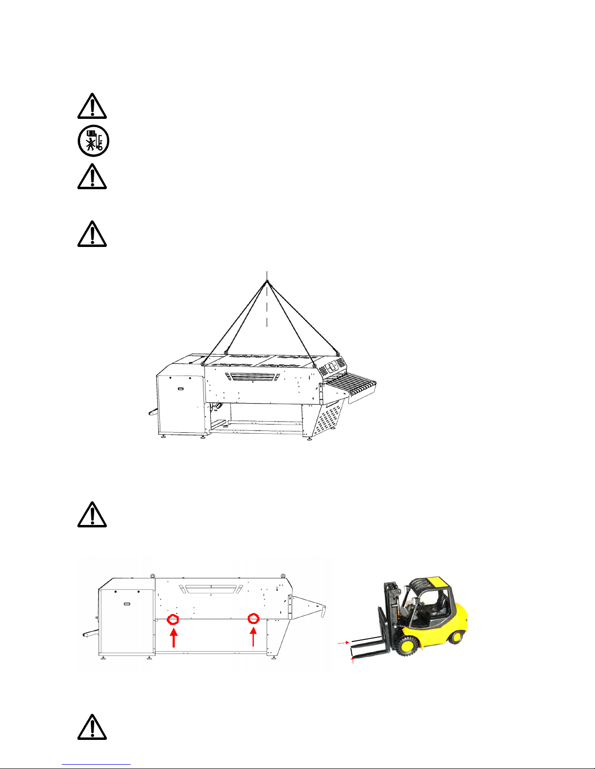
The handling of the machine must be done by qualified personnel.
During handing, nobody should be under the load.
The machine must be handled using the hoist rings otherwise you risk in
twisting the machine.
Use the hoist rings intended for this procedure.
Make sure that the machine is properly balanced.
An elevator carriage should only be used if the following conditions are
met: the elevator carriage«forks» must span the entire wid th of the FT -SMART.
V erify that the forks do not touch the st acker flaps.
< 45°
1600
1600
Page 21
21 FT-M1211A
2.2 INST ALLATION
The floor must be level and capable of supporting the weight of the machine.
The machine must be put by level with regard to the ground
- Connect the compressed air to the main air supply , which must be equipped with a shut off
valve.
- Connect the electricity to the differential circuit breaker corresponding to the machine,
previously installed.
- Check that the voltage of the machine and the factory are compatible.
- Check the pressure for the compressed air.(6 bars recommended)
- Remove the links which maintain the flap s of the st acker .
2.3 CONNECTING TO THE ELECTRIC AND AIR SUPPLIES.
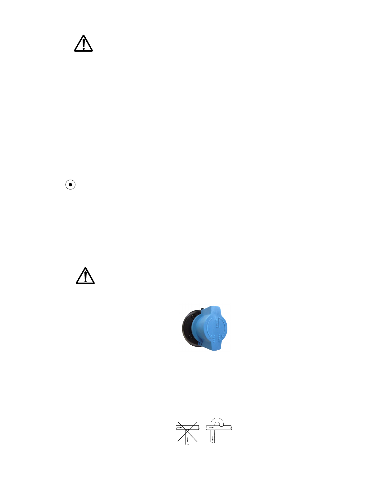
Connecting to the air supply:
The machine is equipped with a central compressed air system with a manometer, a reduction valve and an air filter.
The machine is equipped with an air treatment assembly:
Filter / Regulator / Lubricator (See chapter 5 Maintenance procedures).
The client is responsible to bring the air supply up to the shut off valve.
Additionally , this air must be dry and free of dust.
T o supply the machine, it is necessary to use a hose with a minimum diameter of 15/21
(1/2 pouce).
The air supply must have a constant pressure of 6 bars minimum, in order to obtain, a
decent regulation and to avoid malfunctioning due to drops in pressure.
In the case where the air supply is below the suply point for the machine, foresee the
appropriate connectors.
NOTE : Not respecting these conditions will lead to the poor functioning of the
material.
Page 22

FT-M1211A 22
Connecting to the electrical supply
The electrical installation of the machine must only be performed by qualified
personnel.
- - Make sure that the supply voltage is correct and that the wattage of your system is sufficient
before connecting the machine.
The supply cable should be protected at the head of the line ( at the circuit breaker box)
* Gauge 4 mm² in 230V .
* Gauge 2.5 mm² in 400V .
* 3 phase cable
- Connected by a 4 conductor cable.
L1 Phase 1
L2 Phase 2
L3 Phase 3
PE Ground wire
All of the electrical connections with the machine that preceed must be connected following
the norms in vigor
For more details refer to the electric schemas of the machine(s)
Note: Not respecting these conditions will lead to a deterioration of the electrical
and mechanical elements as soon as the machine is put into use.
Adjustments after machine is in place:
- Test the voltage and the direction of the rotation of the motors.
The adjustment of the speed is done with the aid of the SCHNEIDER touch screen, see the
section Automation.
L1
L2 L3
Page 23
23 FT-M1211A
2.4 TESTING
The testing of the machine should be conducted only by qualified personnel.
The machine should be tested with all the types of articles before the machine is actually
put into use.
Assure that the first pieces of laundry are, if possible, second-rate articles in good condition.
Once the installation is operational, management and maintenance staff should be trained
so that they are familiarized with the machine.
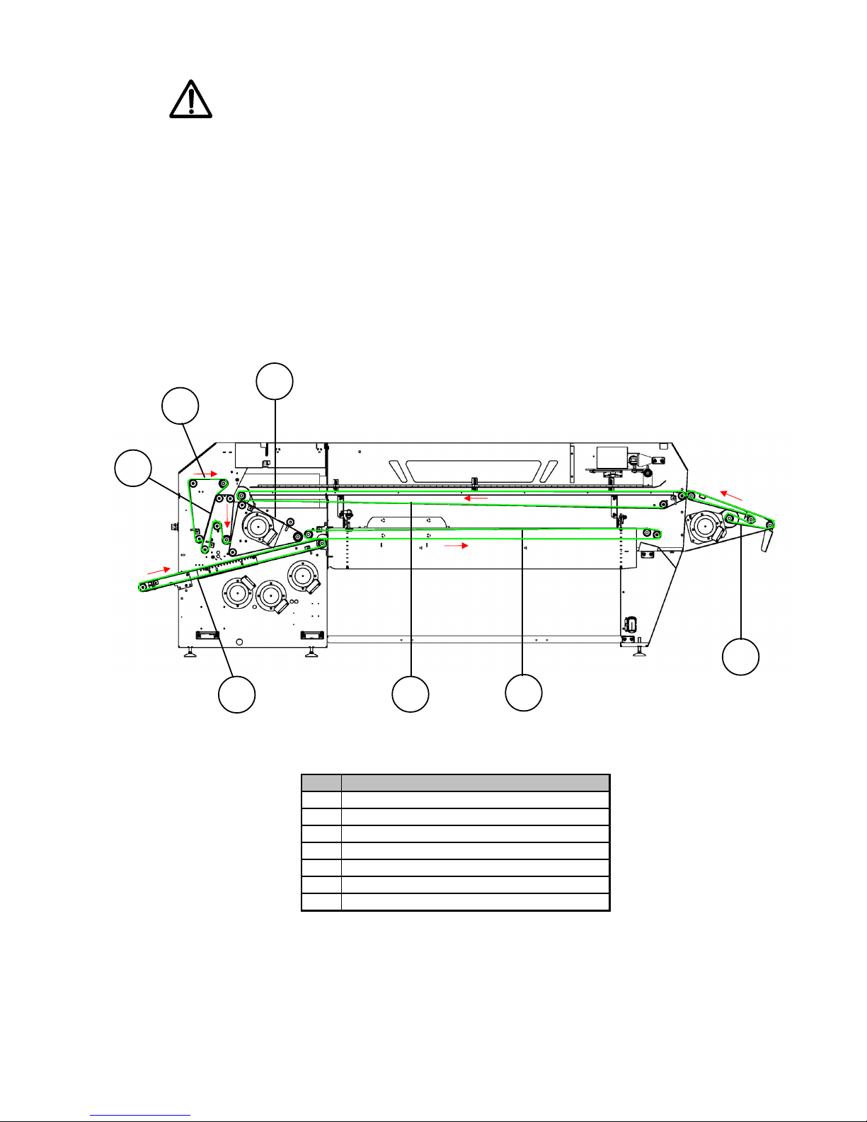
2.4.1 CHECK OF THE SENSE OF ROTATION OF MOTORS
Rep Designation
1 Conveyor feeding
2 Conveyor folding table
3 Reversible conveyor "Boomerang"
4 Reversible conveyor "W"
5 Conveyor delta
6 2éme fold reversible conveyor
7 Flap stacker conveyor
1
7
2
6
4
3
5
Page 24
FT-M1211A 24
3 SAFETY
3.1 GENERALITIES
It is imperative that the Chapter 1 General Precautions be read and respected.
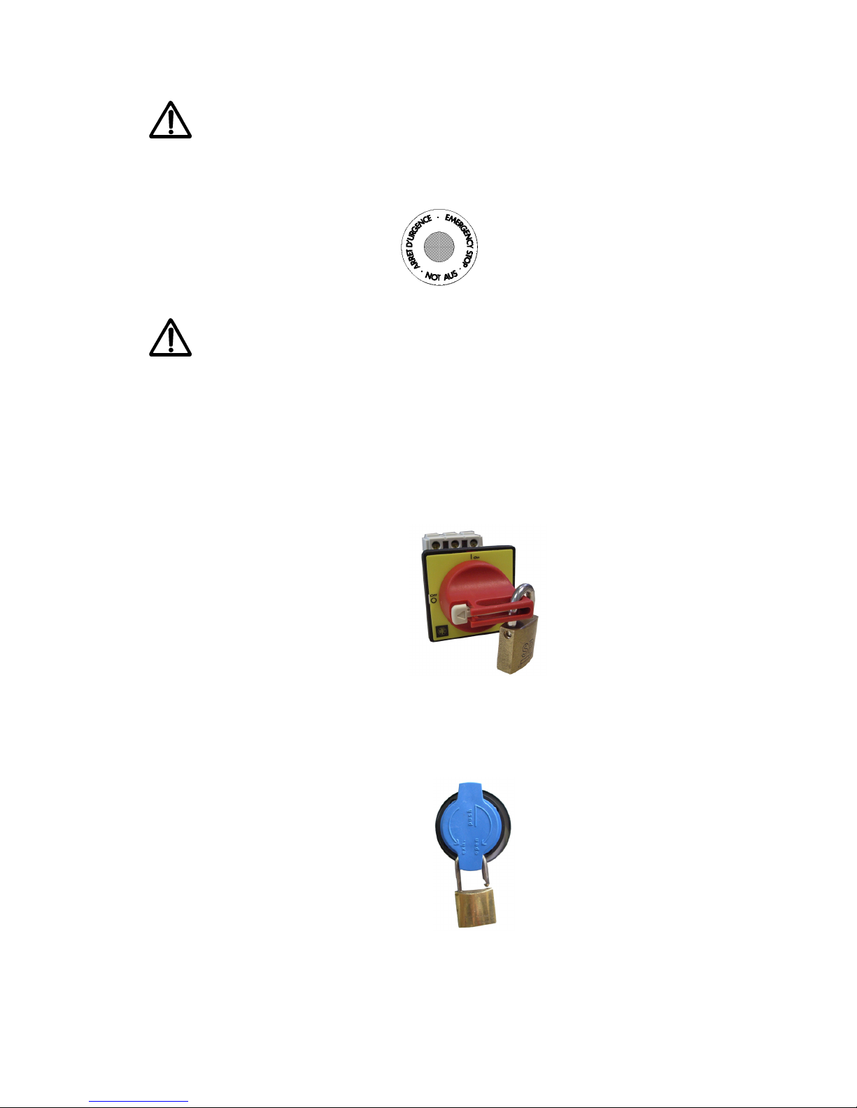
Emergency Stop of the machine :
- Press the button Emergency Stop :
The machine remains in the position that it was in just prior to the moment it was stopped.
The machine should be put back into operation only by the person in charge by
pushing the reset button and is to do so only after having ensured that there is no longer
any danger.
Resetting the machine is authorized if and only if:
- None of the emergency stop push-buttons are still activated,
- All of the moveable guard cont acts are activated,
3.2 STOPPING THE MACHINE
- -Place the main selector into the OFF
position.
padlock not supplied
- Close the air supply valve and padlock it.
padlock not supplied
Page 25
25 FT-M1211A
3.3 INTERVENTION DURING OPERATION
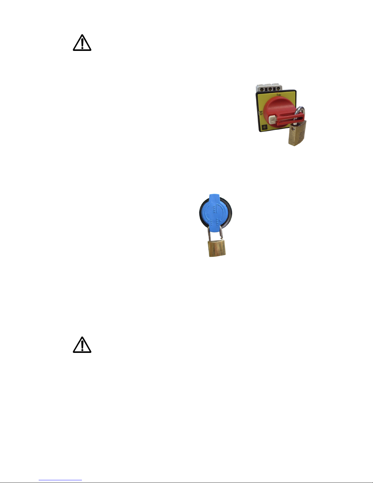
It is strictly forbidden to intervene while the machine is operating
It is essentail that before any intervention the machine has come to a complete stop to:
- Place the main ON/OFF selector in the OFF position and
padlock it
padlock not supplied
- Close the air supply valve and padlock it.
padlock not supplied
The opening of the different mobile safety sensors will automatically shut down the
machine.
The machine can only be put back into operation once all of the elements of the safety
system are reset. It is therefore necessary to frequently test that they function properly .
NEVER ATTEMPT TO EITHER REMOVE OR MODIFY ANY OF THE SAFETY
DEVICES.
If a particular intervention requires any of the fixed protectors to be dismantled ( for
example, hood, bolted grill, ect.), it is necessary to place the principal selector in the OFF
position and padlock it and to close the air supply valve and padlock it.
Before starting back up the machine, ensure that all of the safety protectors have
been remounted and that the keys have been removed from the electrical
cabinets.
Page 26

FT-M1211A 26
4 PRINCIPLES AND FUNCTIONING
4.1 PRINCIPLES
Articles that can be folded :
This is an independant machine for folding laundry . It is designed to fold ironed or wrung-out
laundry such as terry cloth towels, dish towels, T -shirts, ect. These articles can be made out
of terry cloth, linen, cotton and different types of polyester-cotton.
Dimensions for articles to be treated.
• Min width : 260 mm
• Max width: 1200 mm
• Min length: 250 mm
• Max length:: 2350 mm
Rectangular items : for items or other forms including strips or edging, it is best to ask the
laboratory to test.
Folding template
• Width (min x max) : 130mm x400mm
Machine production capacity
Instantaneous production : 800 to 1200 pieces /hour , according to the type of article and the
ability of the operator.
The speed of the conveyor belts is 50 m/min (170 ft/min) for 50Hz.
All of the cross folds are made by a jet of air in combination with the inversion conveyor belt.
All of the cross folds made and raised are considered complete pieces.
The standard machine possesses 3 stacker conveyors of 650mm, 4 stacker conveyors of
415mm and a central conveyor belt which brings the pile to the operator on the right or left
side of the machine. The machine is programmed to sort out the items in 3 categories only
that it contains 3 or 4 stacker flaps.
The different folding programmes can be accessed by using the touch screen.
Do not attempt to remove an item that has already been loaded into the ma-
chine.
Any anomaly of the feeder must be immediately reported to the person in
charge.
Page 27
27 FT-M1211A
4.2 FUNCTIONING
Make sure that nobody puts their hands in the machine.
Verify that all of the protections are in place and that nobody is working on top
of or under the machine
Before starting the machine, check:
- The direction of rotation of the motors,
- The air pressure, which should be 6 bars.
Starting the machine :
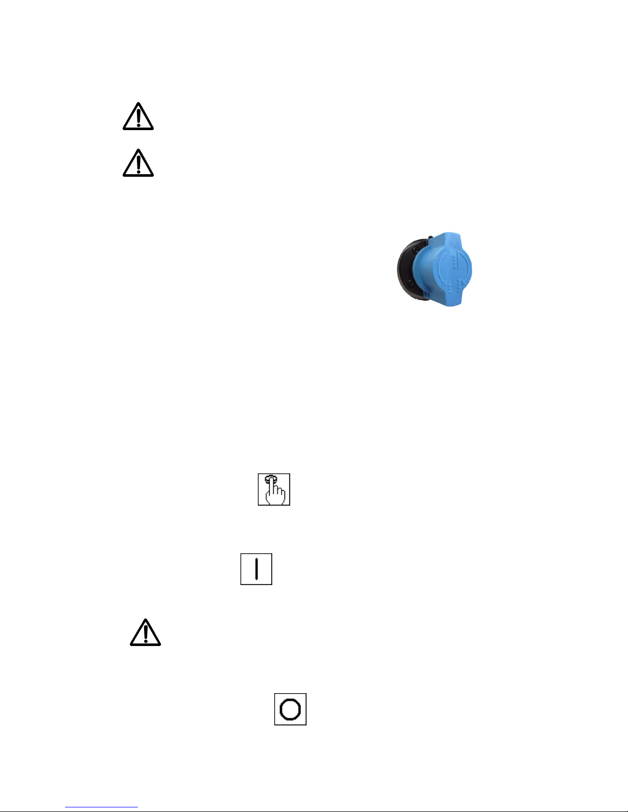
- Open the compressed air-supply valve.
- Check the pressure.
- - Put the main switch into the ON position.
Once all of the safety measures have been taken: :
- Push the RESET button
Once all of the defaults have been cleared:
- Push the ON button
Stopping the machine:
- Check that all of the pieces of laundry have been discharged.
- Push the STOP button .
Page 28

FT-M1211A 28
Put the main switch into the OFF position.
-Close the compressed air supply valve
Page 29
29 FT-M1211A
5 MAINTENANCE PROCEDURES
5.1 GENERAL MAINTENANCE
NOTE : Time of maintenance estimated are calculated for a person competent and formed
in our machine. They are given as a rough guide, without engaging the responsibility of
GIRBAU.
Before any intervention:
- Put the main switch in the OFF position and padlock it.
- Close the compressed air-supply valve and padlock it.
Everyday or every 10 hours (Estimated time of maintenance: 10 minutes)
- Remove any texile articles that remain in the machine.
- Remove the dust from the photocells
- Empty the air filters and fill the lubricator
- Visually inspect the sedimentation canister for the air supply filter (normally empty), see
chapter Air filter/regulator maintenance.
NOTE : If necessary , increase the frequency of the visual inspections to check that the
filter does not fill up during the day . If this does happen, purge the sedimentation canister
filter.
Correct any errors, repair or change any defective pieces
NEVER MODIFY OR REMOVE A SAFETY DEVICE. THE MANUFACTURER
DECLINES ANY RESPONSIBILITY IN CASE OF DISREGARD OF THE PRESENT
INSTRUCTIONS OF SAFETY AND ANY INFORMATION INCLUDED IN THE
CORRESPONDING NOTES
Every week or every 50 hours (Estimated time of maintenance: 15 minutes
including the previous regular maintenances)
- Remove the accumulated dust on the belts and check the condition of the cross fold belts.
- Check the inputs and the outputs on the touch screen.
- Entirely clean the machine
- Test the safeties
- Visually inspect the belts
After the 1st month of use or the 200 first hours (Estimated time of maintenance:
30 minutes to 1 hour if retighten the belts)
- Check the tension of the belts and retighten if necessary .
- Check the nuts and bolts and retighten if necessary
- Check the entirely of the machine.
- Check that all the drive-train components are properly attached
- Check and oil all of the joints
- Verify the p arallelism of the stackers
- Purge both reservoirs of air of the longitudinal blowing
Page 30
FT-M1211A 30
Every month or every 200 hours (Estimated time of maintenance : 2 hours
including the previous regular maintenances)
- Clean the compressed air treatment filter, see Chapter Maintenance of filter/
Regulator/ Air lubricator
- Check the straps and their staples and replace those that are damaged
- Pneumatic control :
Pneumatic regulation of the stacker and shuttles stacker (elimination of the vibrations)
Pressure of regulation of the reservoirs of air for the longitudinal foldings
Purge of the longitudinal reservoirs of air of blowing
Annual maintenance or every 2400 hours (Estimated time of maintenance : 5
hours including the previous regular maintenances)
- Check all of the bearings and joints, replace them if necessary .
- Check the strut cylinders, replace them if necessary .
- Check that the air hoses are not damaged, replace them if necessary .
- Check all of the drive-train components, repair if necessary .
- Check the straps and replace those that are damaged. Replace all the belts elastics of
the transverse module and the belts felts of the stackers
- Check the belts and clean the accumulated dust on the drive-train pulleys.
- Check all of the machine’s functions, as done so during installation
- Check the location of rolls
- Change the filtering cartridge of the FRL
Every 3 years or every 5000 hours (Including the previous regular maintenances)
- Complete Revision of the machine
Checking the safety devices
- Each week check for the proper functioning of the emergency stop button and other safety
sensors.
Maintenance, adjustments and repairs should only be conducted when the
machine is stopped.
Page 31
31 FT-M1211A
5.2 SERVICING OF THE FILTER / REGULATOR
GE NE RAL USAGE CONDITIONS
Fitting and commissioning are to be carried out only by authorized trained personnel
in accordance w ith the operating instructions. These products are intended for use
exclusively with compr essed air.They are not suitable for use with other media
(fluids or gases).
1 - APPLICATION
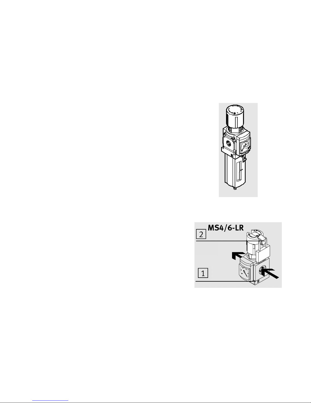
As designed, the filter control valve MS4/6-LFR and
pressure control valve MS4/6-LR(B) control the work
pressure set in the following string. The MS4/6LFR/LR(B) thereby smooths out: fluctuations in
pressure. The filter control valve MS4/6-LFR and
filter MS4/6- LF with centrifugal separator remove dirt
particles and condensate
2 - CONDITI ONS O F USE
• Compare the maximum values specified in these
operating instructions w ith your actual application
(e.g.pressures, torques). Only if the loading limits are
observed can the product be operated in accordance
with the relevant safety guidelines.
• Remove dirt particles in the supply lines by blowing
out the tubing with compressed air. In this way you
will protect the device from premature failure or
heavy wear (see DIN ISO 4414, section 9.4)
• Use the product in its original state without
undertaking any modifications.
3 - FITTING MECHANICAL COMPONENTS
• Use shut-off valves in the compressed air tubing for
exhausting the system (e.g. for replacing a filter).
• Note the direction of flow from 1 to 2. The figure1on
the product housing serves as an orientation
• Place the MS4/6-LF… with sufficient space
underneath the filter bowl (min. 100 mm).
This facilitates replacing the filter cartridge.
.
Page 32
FT-M1211A 32
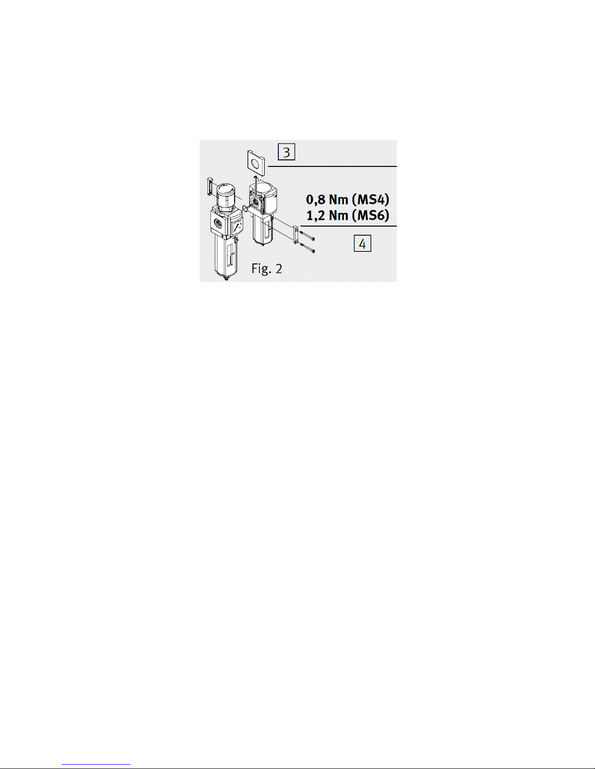
Fitting together with an alr
eady fitted ser vice unit of the
same series (_Fig. 2):
1
.Remove the cover plates3on the sides to be fitted together (push upwards).
2
.Place the module connectors MS4/6-MV4 in the
grooves of the individual units. There must be
a
seal between the individual units.
3
. Insert two screws into the module connectors.
F
itting pneu m atic com p on e n ts
U
sing screw connectors with width across flats larger than A/F 17 (MS4)/ A/F 24 (MS6):
•
Remove the cover3(push upwards).
W
hen using screw connectors:
•
Note the screw-in depth of the connector thread. Screwing in deeply reduces the flow.
•
Screw the connectors into the pneumatic connections using a suitable sealing material.
4
COMMISSIONING
S
etting pressure reg ulat o r MS4/6-LFR / LR(B):
1
.Pull the press ure adjustment button upwards away from the housing (if necessary remove
p
adlock and push in the unlocking device2).
2
.Close the pressure adjustment button completely in the direction “–”.
3
.Pressurize your system slow ly.
4
.Open the pressure adjustment button in the direction “+” until the desired pressure is shown
o
n the manome ter .
T
he maximum permitted work pressure on the type plate must not be exceeded. If the supply
p
ressure is correct, it will be at least 0.5 bar higher than the output pressure.
5
.Press the pressure adjustment button downwards towards the housing. The button will then
l
ock itself against unintentional turning.
I
f required:
•
Press the unlocking device2outwards.
A padlock LRVS
-D secur es the unlocking device.
Page 33
33 FT-M1211A
5
CA RE AND MA INTENANC E
C
ondensate level approx. 10 mm below the filter element (_marking8).
F
ilter/water separator empties automatically (manual emptying:
T
urn the drainage screw 9 in an anticlockwise direction as seen from below).
T
he cond ensate will then flow out.
B
arbed fitting connection for tubing PCN-4-NT already fitted.
R
eplace the filter cartridge if it shows signs of the following:: Low flow despite
u
nmodified pressure setting.
1
- Exhaust the unit.
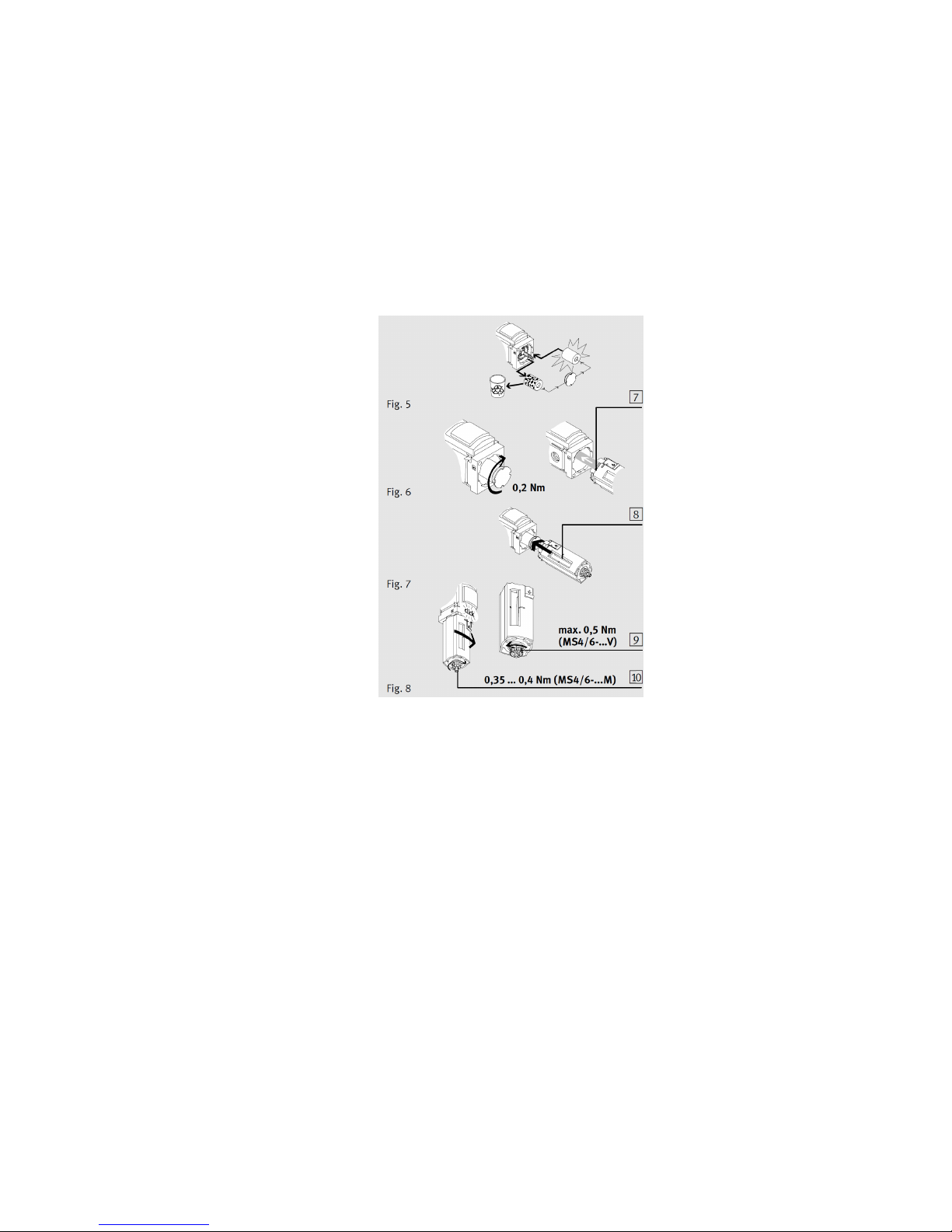
2
.Carry out the following steps (_Fig. 3):
– Push the unlocking slide5in the direct. of the arrow.
– Turn the filter bowl in an anti-clockwise direction (as seen from below).
– Pull the filter bowl away from the unit.
3
.Tur n the filter plate6(in the case of MS4/6-LFM/LFX the complete filter cartridge) i
n
a
n anti- cl ock wis e direc tion.
4
.Replace the filter cartridge if the pores are dirty (_Fig. 5). Grasp the filter cartridge
o
nly at the lower end when it is new. A support span is fitted in the new 5 μm filter
c
art ridge.
5
. Fit the individual parts again in the reverse sequence.
T
he following checks must then be made:
– the locking pin7of the filter bowl must face the large recess in the housing
.
– the unlocking slide must be heard to clip into place when the end stop is
reached (_Fig. 8).
Page 34
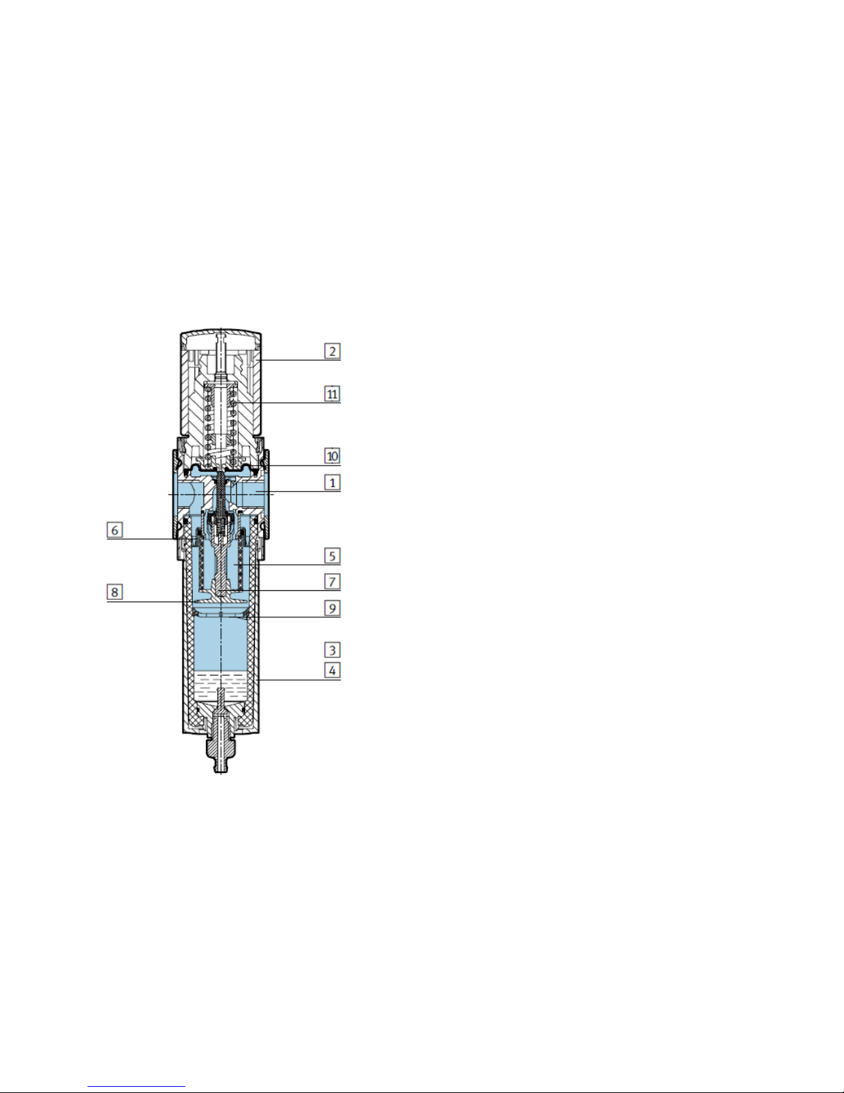
FT-M1211A 34
1
Housing Die-cast alumi nium
2
Rotary knob PA/POM
3
Plastic bowl guard PC
Metal bowl
Wrough t alum i niu m allo y,
die-cas t al u mi n i um
4
Inspection window PA
5
Filter element PE
6
Spin disc POM
7
Filter holder POM
8
Separating plate POM
9
Stabilising disc POM
10
Diaphragm NBR
11
Spring Steel
Seals NBR
RoHS-compliant (not with
va r ia nt E1 , E2, E3 o r E 4)
Note on materials
Free of copper and PTFE
only with cove r plate VS
6-.
Complete re
-
commissioning of the MS4/6
-
LFR in
accordance with the chapter
“
Commissioning”.
M
S4/6- LF/LFM/LFX: Commission the system again.
C
leaning
•
Use only the following cleaning agents:
– water or soap suds (max. +60 °C);
– petroleum ether (free of
aromatic compounds).
Page 35
35 FT-M1211A
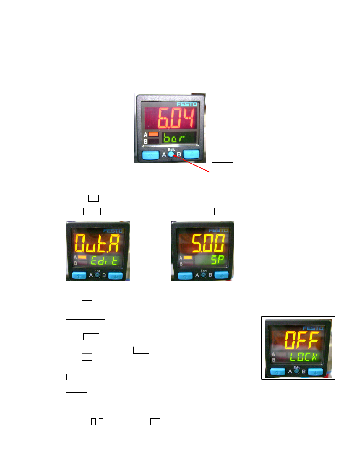
1/ Conn ec t the blue wire to the 0v (4).
-the black wire to the pressure switch input
-the brown wire to the +24v (3)
2
/ Set the pressure to 6 bars using the main pressure regulator.
3
/ Press Ed it.
S
elect O UT A and th en p r e s s sev eral tim es on Edit until SP.
S
et SP to 5 bars (pr es s ur e sw itch t r iggers) us ing the arrow s .
P
ress Edit sev er al times unti l the supply press ur e is dis played.
A
C CES CODE:
T
o enter the acc es s code: Press Edit.
S
el ec t S PEC wi th th e ar ro ws.
P
ress Edit repeatedly until LOCK is displayed.
E
nter the desired code.
P
ress Edit sev er al times unti l the supply press ur e is dis played.
O
F F m e ans th at t he k eybo a rd i s n o t locke d w it h a co de .
R
ESET:
I
f the acce ss code is los t, a res et of the pres s ur e s wit ch is possi ble .
D
i sconnect t he po wer supp ly.
P
ress the A, B (a rrow s) keys and Edit .
C
on nec t t he powe r s up ply aga in.
R
eadjust the settings.
Edit
FESTO SPAB PRESSURE SENSOR PROGRAMMING 14-1051
Page 36

FT-M1211A 36
6 SPARE PARTS
6.1 BASIC EMERGENCY KIT - FT -MAXI - 2011 - 06
6.2 MAINTENANCE KIT - FT-MAXI - 2011 - 06
6.4 MAINTENANCE KIT - L5 - FT -MAXI - 201 1 - 07
6.3 ANNUAL PREVENTIVE KIT OF MAINTENANCE - FT-MAXI - 2011 - 06
Référence Qté Description
10-0178 1 Motor 250W/680Tr/230-400V/50Hz
10-0177 1 Motor brake 250W/680Tr/230-400V/50Hz
10-1210 1 Motor roll cylindrical D80/L44 - 208V
13-3050 1 Disjoncteur contacteur
13-3007 1 Circuit breaker contactor 2,2 - 3,2A
13-3047 1 Circuit breaker contactor inverser 2,2/3,2A
13-3000 1 Contactor control motor 0,28/0,4A
2D 01 90 6 1 Convex alu pulley D40 /L59/D19
Référence Qté Description
15-0034 1 Cell
15-0162 1 Cell
15-0570 1 Inductive sensor
15-0184 1 Impulse generator
ID Qty Description
14-0894 1 Cylinder D32 C50
14-0819 1 Cylinder D25 - L500
15-3189 1 Module 16 inputs BMX DDI I602
15-3194 1 Module 16 output BMX DDO I602
11-0324 12 Crosspiece PA66 D6,2x10 L35
4M05932 1 Motor roll 51x2x120 LG1400 B55,5
4M05922 1 Motor roll 51x2x120 LG1295 B110
4M05921 1 Motor roll 51x2x120 LG983 B55,5
10-0354 1 Push button
10-0557 1 Flat pulley D40
10-0363 1 Roll 50x1,5 LG436/426/ Axle 14
10-0360 1 RF 51x2 L1400-1390 Axle 16xM10
4M05988 1 RF 51 x1 ,5 L915-905 Axle 16xM10
16-0884 1 Belt LA40 LG730
16-0880 1 Belt LA40 LG760
16-0882 1 Belt LA40 LG1125
16-0881 1 Belt LA40 LG2030
16-0876 1 Belt LA40 LG600
Référence Qté Description
2C02514 2 Stapled belt LA100/LG4760
2C01895 5 Stapled elastic cotton belt LA88 - LG831
2C01896 5 Stapled elastic cotton belt LA88 - LG925
14-1126 1 Filtering cartridge
2C01887 10 Felt belt LA95 LG1730
2C01992 4 Stapled belt LA180/LG5985
2C01897 5 Stapled felt belt 1CR LA88 - LG1348
2C02515 5 Stapled felt belt 1CR LA88 - LG2610
Page 37
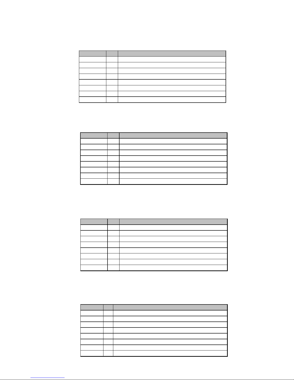
37 FT-M1211A
6.6 MAINTENANCE KIT - M5 - FT-MAXI - 2011 - 07
Référence Qté Description
10-0178 1 Motor 250W/680Tr/230-400V/50H z
10-0177 1 Motor brake 250W/680Tr/230-400V/50Hz
10-1065 1 Roll motor cylindrical D80/L440 220V
13-3007 1 Start motor 2,2/3,2A
13-3047 1 Start motor 2,2/3,2A
13-3044 1 Start motor 0,22/0,32A
13-3050 1 C ontactor control motor
2D01812 1 Convex alu pulley D48/L59/D19
6.7 MAINTENANCE KIT - M6 - FT-MAXI - 2011 - 07
Référence Qté Description
10-1282 1 Motor 250W/830Tr/220-240V/60Hz
10-1283 1 Motor brake 250W/830Tr/220-240V/60Hz B24V
10-1209 1 Roll motor cylindrical D80/L440 400V
13-3007 1 Start motor 2,2/3,2A
13-3047 1 Start motor 2,2/3,2A
13-3044 1 Start motor 0,22/0,32A
13-3050 1 Contactor control motor
2D01812 1 Convex a l u pulley D48/L59/D19
6.5 MAINTENANCE KIT - L6 - L7 - FT -MAXI - 201 1 - 07
Référence Qté Description
10-0401 1 Motor 250W/680Tr/208V/60Hz
10-0402 1 Motor brake 250W/680Tr/208V/60Hz B2
10-1210 1 Roll motor cylindrical D80/L440 208V
13-3050 1 C ontactor control motor
13-3007 1 Start motor 2,2/3,2A
13-3047 1 Start motor 2,2/3,2A
13-3044 1 Start motor 0,22/0,32A
2D01906 1 Convex alu pulley D40/L59/D19
6.8 MAINTENANCE KIT - Q1 - FT-MAXI - 2011 - 07
Référence Qté Description
10-1280 1 Motor 250W/830Tr/440-480V/60H z
10-1281 1 Motor brake 250W/830Tr/440-480V/60Hz B2 4V
10-1270 1 R oll motor cylindrical D80/RL412 440-480V/60HZ/120W/0,72M/S ULCSA
15-3221 1 Start motor 0,9/1,25A
15-3241 1 Start motor 0,9/1,25A
15-3216 1 Start motor 0,28/0,4A
13-3050 1 Contactor control motor
2D 01812 1 Convex alu pulley D48/L59/D19
Page 38
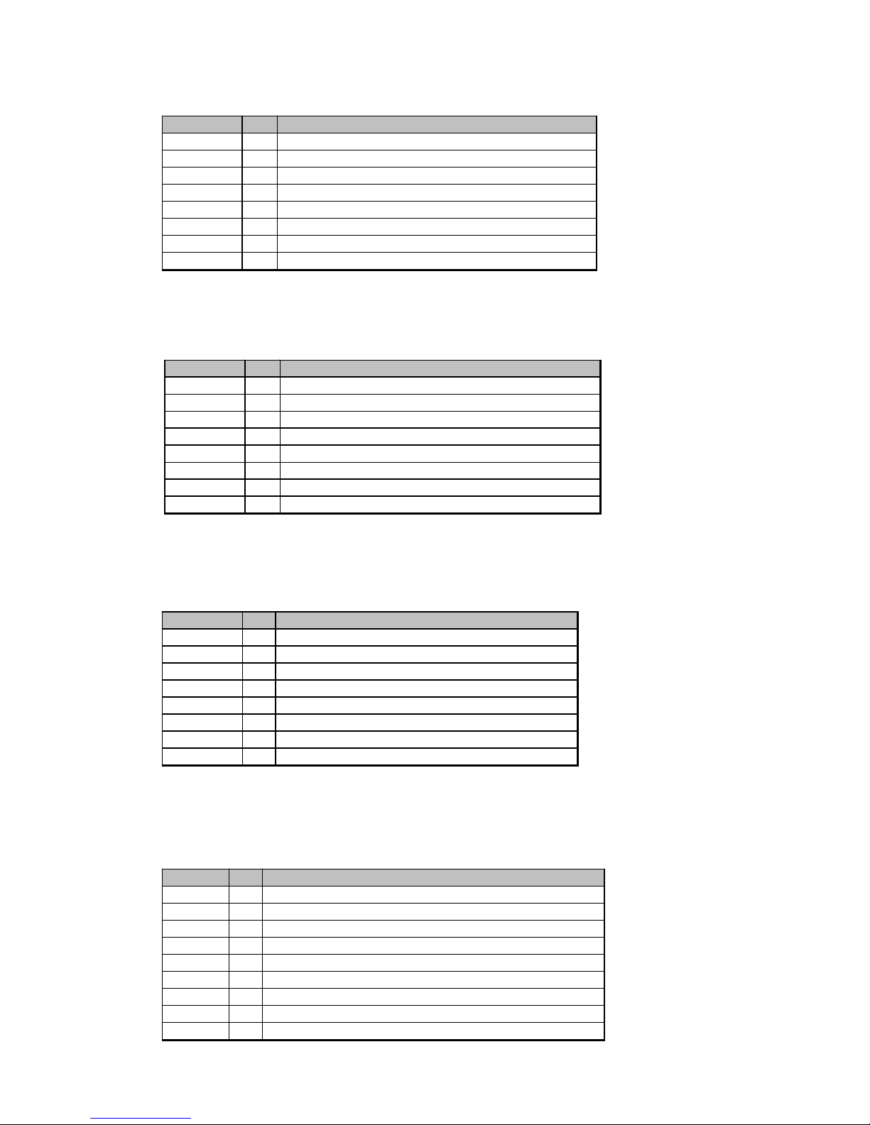
FT-M1211A 38
6.1 1 MAINTENANCE KIT - Q7 - Q9 - FT -MAXI - 201 1 - 07
Référence Qté Description
10-1176 1 Motor 250W/680Tr/480V-60Hz
10-1177 1 Motor brake 250W/680Tr/230-400V-50Hz
10-1209 1 Roll motor cylindrical D80/L440 400V - 75W
13-3004 1 Start motor 0,9/1,25A
13-3064 1 Start motor 0,9/1,25A
13-2999 1 Start motor 0,35/0,5A
13-3050 1 C ontactor commande moteur
2D01906 1 Convex alu pulley D40/L59/D19
6.12 MAINTENANCE KIT - L1 - FT -MAXI - 201 1 - 07
6.9 MAINTENANCE KIT - Q5 - FT -MAXI - 201 1 - 07
Référence Qté Description
10-0178 1 Motor 250W/680Tr/230-400V/50H z
10-0177 1 Motor brake 250W/680Tr/230-400V/50Hz
10-1209 1 Roll motor cylindrical D80/L440 400V
13-3005 1 Start motor 1,1/1,6A
13-3039 1 Start motor 1,1/1,6A
13-3003 1 Start motor 0,55/0,8A
13-3050 1 C ontactor control motor
2D01812 1 Convex alu pulley D48/L59/D19
6.10 MAINTENANCE KIT - Q6 - FT -MAXI - 201 1 - 07
Référence Qté Description
10-1282 1 Motor 250W/830Tr/220-240V/60Hz
10-1283 1 Motor brake 250W/830Tr/220-240V/60Hz/B24V
10-1209 1 Roll motor cylindrical D80/L440 400V
13-3005 1 Start motor 1,1/1,6A
13-3039 1 Start motor 1,1/1,6A
13-3000 1 Start motor 0,28/0,4A
13-3050 1 Contactor control motor
2D01906 1 Convex a l u pulley D40/L59/D19
R éféren ce Qté Description
10-1279 1 Motor 250W/830Tr/208-240V-60Hz
10-1278 1 Motor brake 250W /830Tr-208-240V-60Hz / B24
10-1271 1 R oll motor cylindrical D 80/RL412 208-240V/60HZ - 85W/0,72M/SZ ULCSA
15-3225 1 Start motor 2,2/3,2A
15-3245 1 Start motor 2,2/3,2A
13-3007 1 Start motor 2,2/3,2A
15-3218 1 Start motor 0,45/0,63A
13-3050 1 Contactor control motor
2D 01906 1 Convex alu pulley D40/L59/D 19
Page 39

39 FT-M1211A
TABLE OF CONTENTS
7 EXPLODED VIEWS........................................................................................................................41
4M05675 Feeding table ............................................................................................................. 43
4M05635 Straps - Feeding t able ............................................................................................... 43
4M05632 Feeding table .............................................................................................................. 45
09-0031 Kit................................................................................................................................. 47
4M05674 Frame.........................................................................................................................49
4M05616 Folding table ...............................................................................................................51
4M05622 Central table ............................................................................................................... 53
4M05975 Template ..................................................................................................................... 55
4M05681 St acker flap................................................................................................................ 57
4M05954 Belt guide feeding table..............................................................................................59
4M05698 Cross module meca.................................................................................................. 61
4M05613 Belt guide FT-MAXI ....................................................................................................63
4M05699 Cross module straps.................................................................................................. 65
4M05619 Tubulure of blowing LG985.........................................................................................67
4M05633 Cross module motor ..................................................................................................69
4M05637 Liaison cross + Fold con + Feed con........................................................................71
4M05640 Casing .......................................................................................................................73
09-0145 B (part 2) Kit................................................................................................................. 75
09-0147 A - 09-0165 A Kit..........................................................................................................77
09-0148 A Kit .............................................................................................................................79
09-0124F Kit .............................................................................................................................81
4M05631 Shuttle LU450 ............................................................................................................ 83
4M05646 Shuttle LU450 - Straps ...............................................................................................83
4M05644 Shuttle LU450 - Kit 09-0146A ....................................................................................83
4M05601 Shuttle LU615 ............................................................................................................ 85
4M05636 Shuttle LU615 - Straps............................................................................................... 85
4M05644 Shuttle LU450 - Kit 09-0146A ....................................................................................85
4M05923 Unidirectional roller LU=600....................................................................................... 87
4M05924 Unidirectional roller LU=530....................................................................................... 87
4M05925 Unidirectional roller LU=435....................................................................................... 89
4M05926 Unidirectional roller LU=365....................................................................................... 89
4M05947 Discharge conveyor ..................................................................................................91
4M05634 Discharge conveyor ..................................................................................................91
4M05977 Storage tray options....................................................................................................93
4M05749 Conveyor with free rolls option ...................................................................................95
Page 40

FT-M 121 1A 40
Page 41

41 FT-M1211A
8 EXPLODED VIEWS
Page 42
FT-M 121 1A 42
Page 43
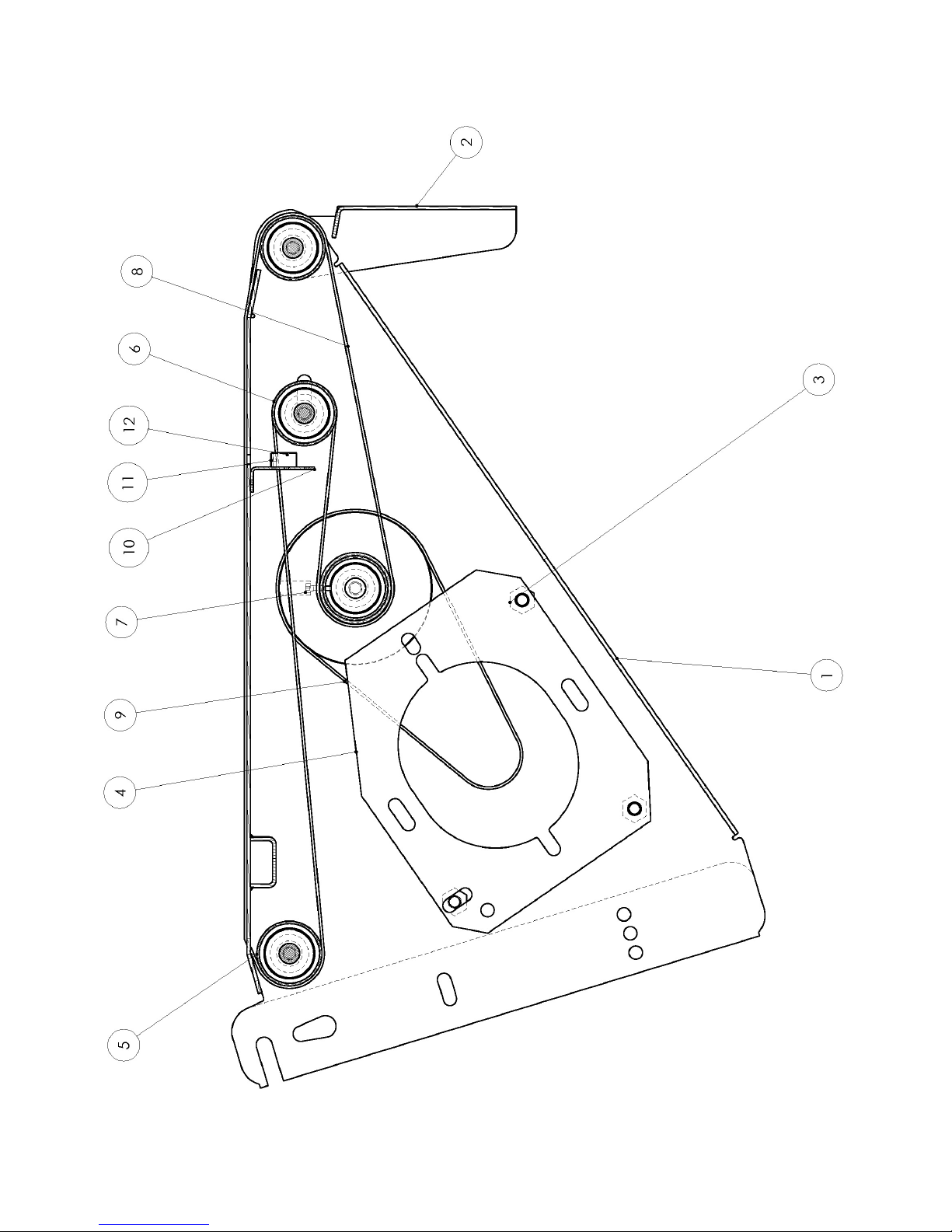
43 FT-M1211A
4M05635 STRAPS- FEEDER TABLE
4M05675 FEEDER TABLE
ID Reference Qty Description
8 2C01887 10 Felt strap 1CR stapled L95 W1730
ID Reference Qty Description
1 2S04691 1 Feeder table reinforcement
2 2T06879 1 Feeder table bib
3 2D01811 3 Motor spacer plate
4 2T06916 1 Counterflange
5 10-0360 2 Roller 51x2 W1400/1395 axle16xM10
6 10-0361 1 Chrome roller 51x2 W1295/1285 axle 16xM10
7 4M05932 1 Motor roller 51x2x120 W1400 B55,5
8 2C01887 10 Felt strap 1CR stapled L95 W1730
9 16-0876 Belt LA40 LG600-TC35ER-JF1
10 2T03557 1 Photocell bracket E3Z
11 15-0162 1 Photocell
12 15-0054 1 Connexion part M8 10m
Page 44
FT-M 121 1A 44
Page 45
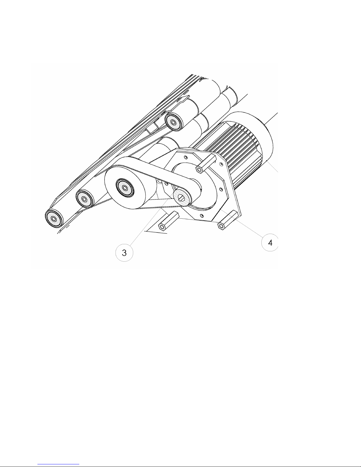
45 FT-M1211A
4M05632 FEEDER TABLE L6-L7
4M05632 FEEDER TABLE M5-Q5
4M05632 FEEDER TABLE M6 - Q6
4M05632 FEEDER TABLE Q1
4M05632 FEEDER TABLE Q7-Q9
ID Reference Qty Description
2 10-0401 1 Motor 250W-680Tr-208V - 60HZ
3 2D01906 1 Convex alu pulley D40/L59/D1L
4 2T07451 1 Motor flange
ID Reference Qty Description
2 10-1280 1 Motor 250W -830Tr/440-480V- 60HZ
3 2D018 12 1 Convex alu pulley D48/L59/D1L
4 2T07451 1 Motor flange
ID Reference Q ty Description
2 10-1176 1 Motor 250W-680Tr-480V - 60HZ
3 2D01906 1 Convex alu pulley D40/L59/D1L
4 2T07451 1 Motor flange
ID Reference Qty Description
2 10-0178 1 Motor 250W-680Tr-230-400V - 5Z
3 2D01812 1 Convex alu pulley D48/L59/D1L
4 2T07451 1 Motor flange
ID Reference Qty Description
2 10-1282 1 Motor 250W-830Tr-220-240V - 60HZ
3 2D01906 1 Convex alu pulley D40/L59/D1L
4 2T07451 1 Motor flange
4M05632 FEEDER TABLE L5
ID Reference Qty Description
2 10-0178 1 Motor 250W-680Tr-230-400V - 50HZ
3 2D01812 1 Convex alu pulley D40/L59/D1L
4 2T07451 1 Motor flange
4M05632 FEEDER TABLE L1
ID Reference Qty Description
2 10-1279 1 Motor 250W-830Tr-208-240V - 60HZ
3 2D01812 1 Convex alu pulley D40/L59/D1L
4 2T07451 1 Motor flange
Page 46
FT-M 121 1A 46
Page 47

47 FT-M1211A
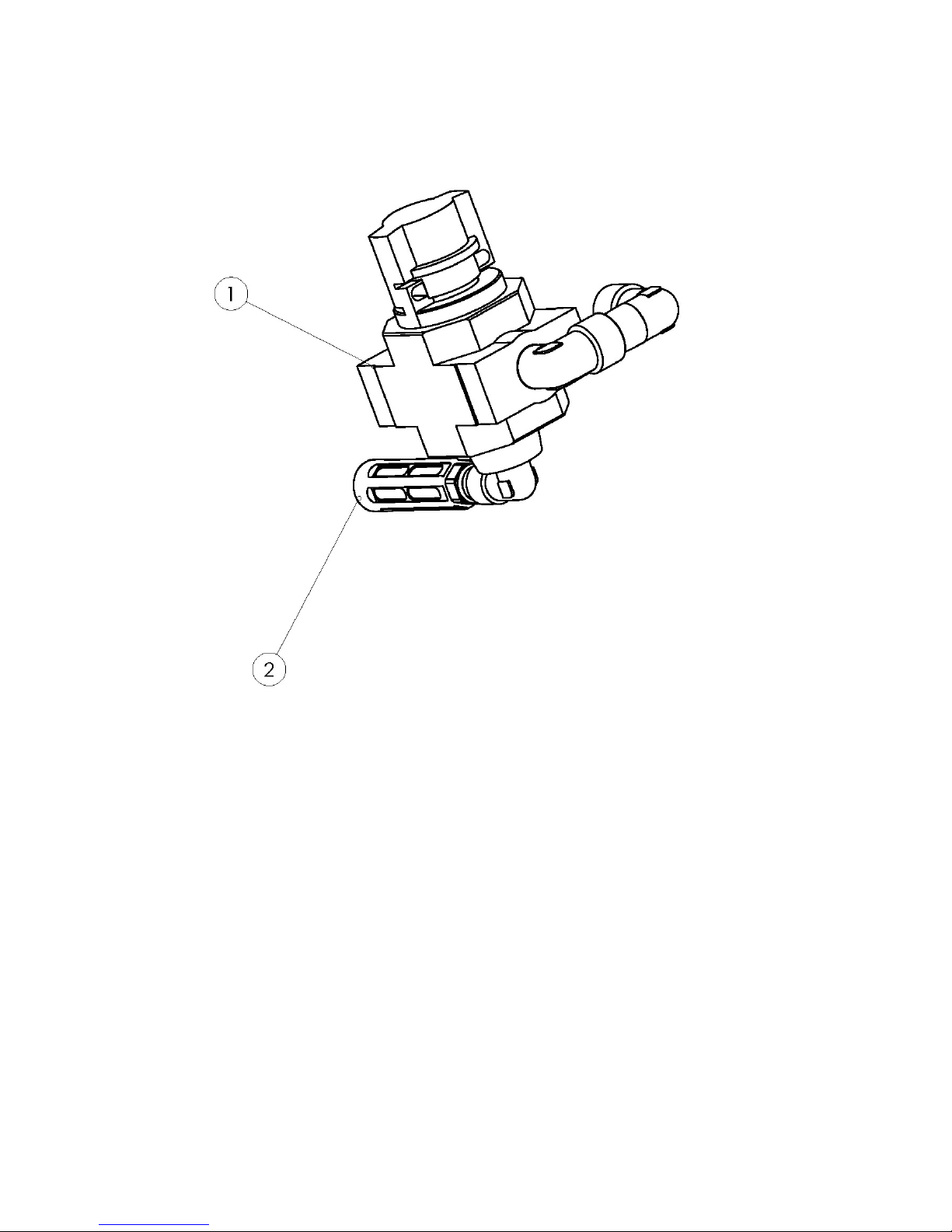
KIT 09-0031 (PART 1)
ID Ref Qty Descripti on
1 14-0967 1 Distributor
2 14-0968 1 Silencer U-3/8 B
Page 48
FT-M 121 1A 48
Page 49

49 FT-M1211A
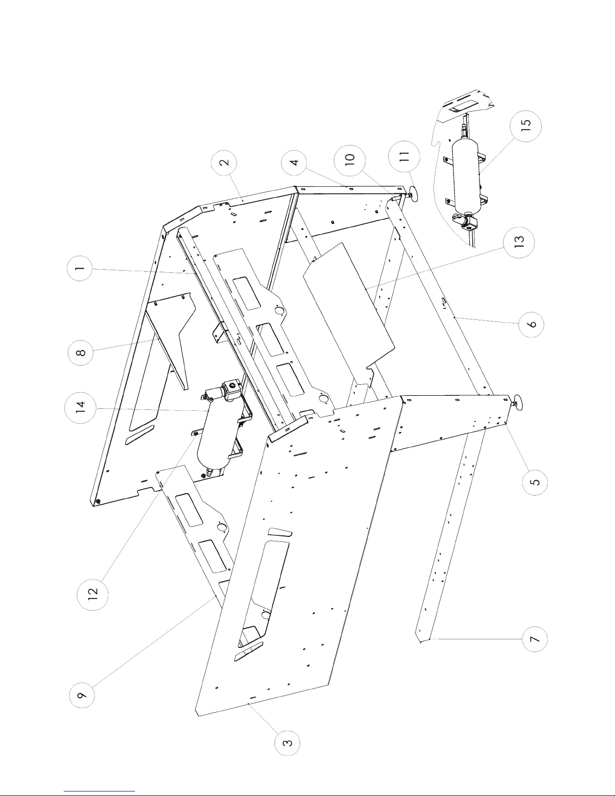
4M05674 FRAME
ID Reference Q ty Description
1 3S01569 1 Cross support beam
2 2S04676 1 Right side frame
3 2S04675 1 Left side frame
4 2T06882 1 Left leg assembly
5 2T068 83 1 Right leg assembly
6 2S04692 2 Cross brace
7 2T069 56 2 Longitudin al cross brace
8 2T068 91 1 Template boomerang guard
9 2T06935 2 Back frame brace
10 12-0393 2 Foot bolt M16x100xD15
11 12-0394 2 Base PA D80 D15
12 2T07003 4 Reservoir bracket
13 2T07013 1 Jet deflector
14 09-0147A 2 Tank left
15 09-0165A 1 Tank right
Page 50
FT-M 121 1A 50
Page 51
51 FT-M1211A
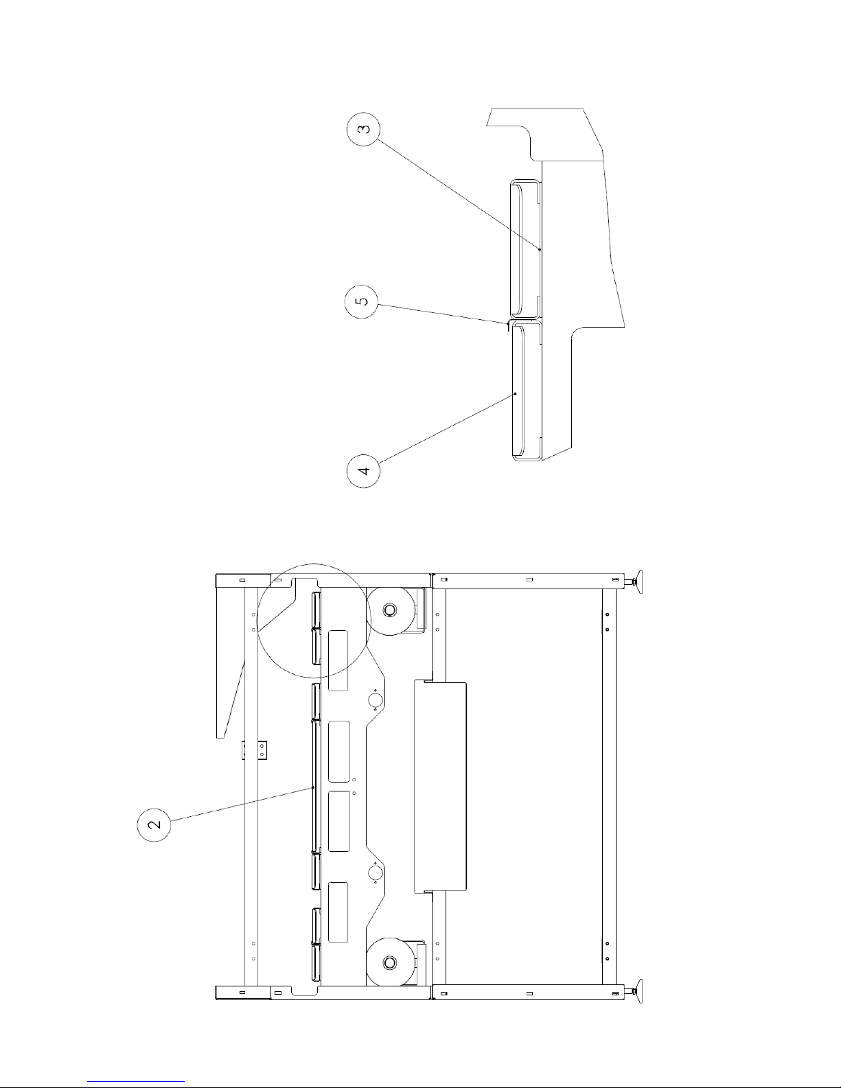
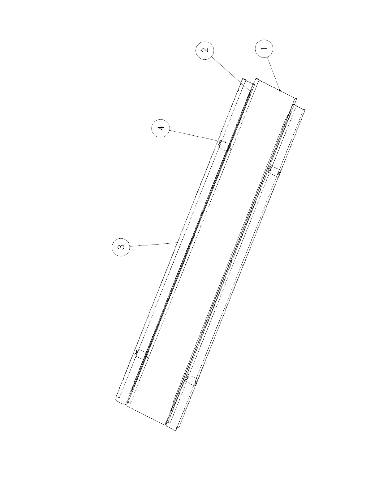
4M05616 FOLDING TABLE
ID Reference Qty Descri ption
2 4M05622 1 Central table
3 2T06927 4 Plate L116/ W60/E2
4 2T06926 4 Sheet m etal cover L2779/W120/H20/E2
5 2T06931 2 Corner piece W20/H10/E1/L2600
Page 52
FT-M 121 1A 52
Page 53
53 FT-M1211A
4M05622 CENTRAL TABLE
ID Reference Qty Descripti on
1 2T06929 1 Sheet metal cover L2829/W440/H2 0/E2
2 2T06931 2 Corner piece W20 /H10/E1/L2600
3 2T06926 2 Sheet metal L2779/W120/H20/E 2
4 2T06927 4 Plate L116/W60/E2
Page 54
FT-M 121 1A 54
Page 55

55 FT-M1211A
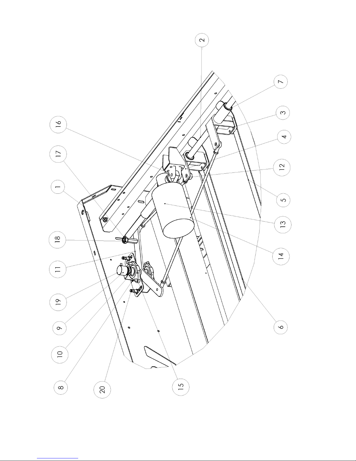
4M05975 TEMPLATE
ID Reference Qty Descri ption
2 2D01821 1 Axle D25/L1394
3 2S04646 1 Left ski guide
4 2S04647 1 Right ski guide
5 2S04694 1 Left ski
6 2S04696 1 Right ski
7 10-0358 4 Ball-bearing bushing Øi25/Øe35/L4 0
8 2T07601 1 Arm support bracket V2
9 2T06801 1 GIO bracket
10 10-0200 2 Flange Ø20/2 holes
11 2S04645 1 Moving arm
12 10-0208 4 Clevis ball joint M10
13 03-0620 0385 1 Galvanized threaded rod M10 L0385
14 03-0620 0675 1 Galvanized threaded rod M10 L0675
15 11-0153 2 Hex bolt CHC M10-25
16 18-0024 1 Electric strut cylinder
17 2D01830 1 Boss D20/W48/D9
18 10-0224 1 Swivel M10
NR 1 5-018 4 1 Impulse generator
NR 15-0570 2 Captor
Page 56
FT-M 121 1A 56
Page 57

57 FT-M1211A
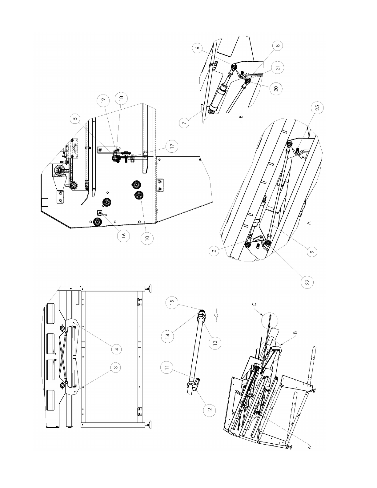
4M05681 STACKER FLAP
ID Reference Qty Descri pti on
2 10-0103 4 Bearing support braket 12
3 2S 0472 7 1 D eposit flap right
4 2S04728 1 Deposit flap left
5 2D01828 2 Boss D20/W25/M10
6 10-0975 2 Swivel M10x1,2F
7 14-0894 2 Strut cylinder D32 C50 DF/AP
8 10-0208 4 Swivel M10
9 03-0620 0500 2 Galvanized threaded rod M10 L0500
10 10-0360 4 Roller 51x2 W1400/1395 Axle16xM10
11 11-0323 6 Cross brace H10/L20/L18 - M6 - L10
12 12-0118 6 Hose clamp for tube Ø14
13 2P03085 2 Blower
14 14-0880 4 Ri ght link ring + nut 1/2, tube 14
15 14-0410 4 Right auto link 3/8 - 8/10
16 4M05954 1 Belt guide
17 11-0160 2 Screw 6 pans CHC M 10-60
18 11-0025 8 Nut H10
19 11-0013 8 Nut HM10
20 11-0230 4 Screw HM 10-40
21 2D01964 4 Screw
Page 58
FT-M 121 1A 58
Page 59

59 FT-M1211A
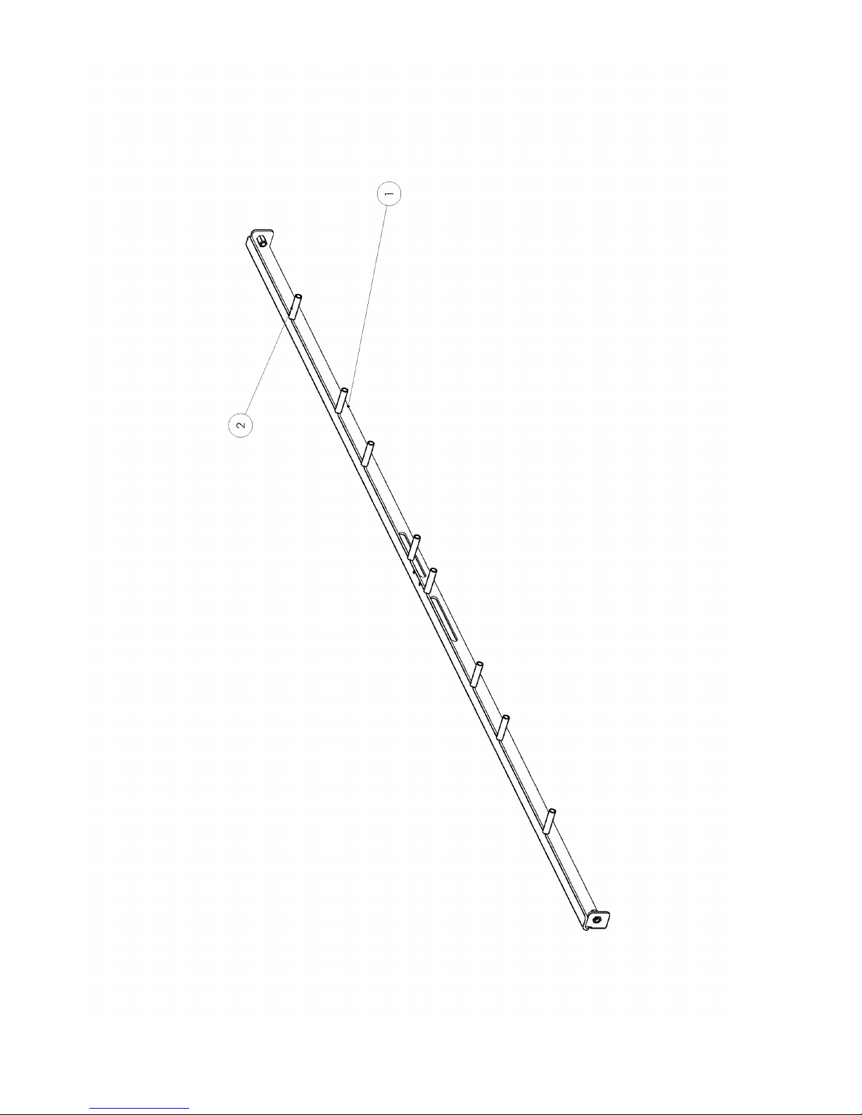
4M05954 BELT GUIDE FEEDING TABLE
ID Reference Qty Description
1 2T07602 1 Simple belt guide
2 11-0324 8 Crosspiece PA66 D6,2x10 L35
Page 60
FT-M 121 1A 60
Page 61

61 FT-M1211A
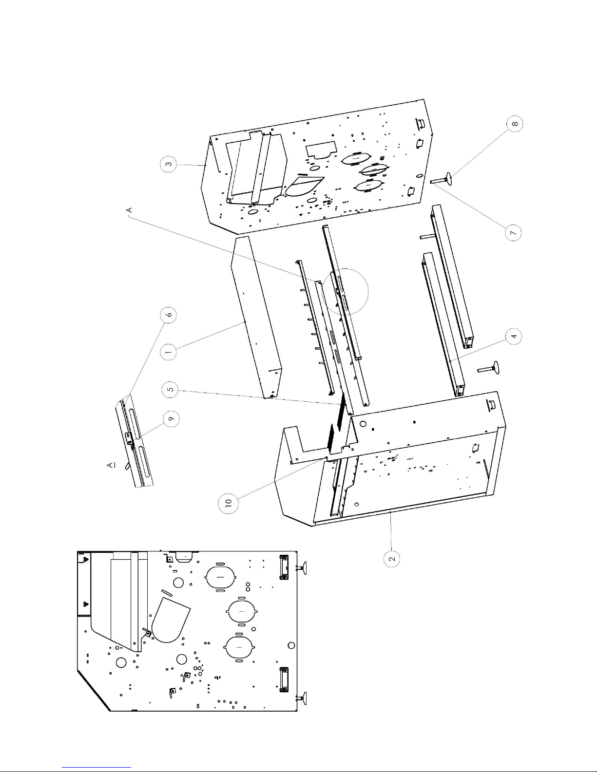
4M05698 CROSS MODULE MECA
ID Reference Qty Description
1 2T06989 1 Upper cross piece
2 3S01573 1 Left cross casing - electric
3 3S0 1574 1 Right cross casing - pneumatic
4 2T06946 2 Lower cross piece
5 4M05613 3 Strape guides
6 2T06947 1 Photocell support plate
7 12-0393 4 Footing bolt M16x100xD15
8 12-0394 4 Footing base PA D80 D15
9 2T03557 1 Photocell bracket E3Z
10 2P03172 2 Brush LG=445
Page 62
FT-M 121 1A 62
Page 63

63 FT-M1211A
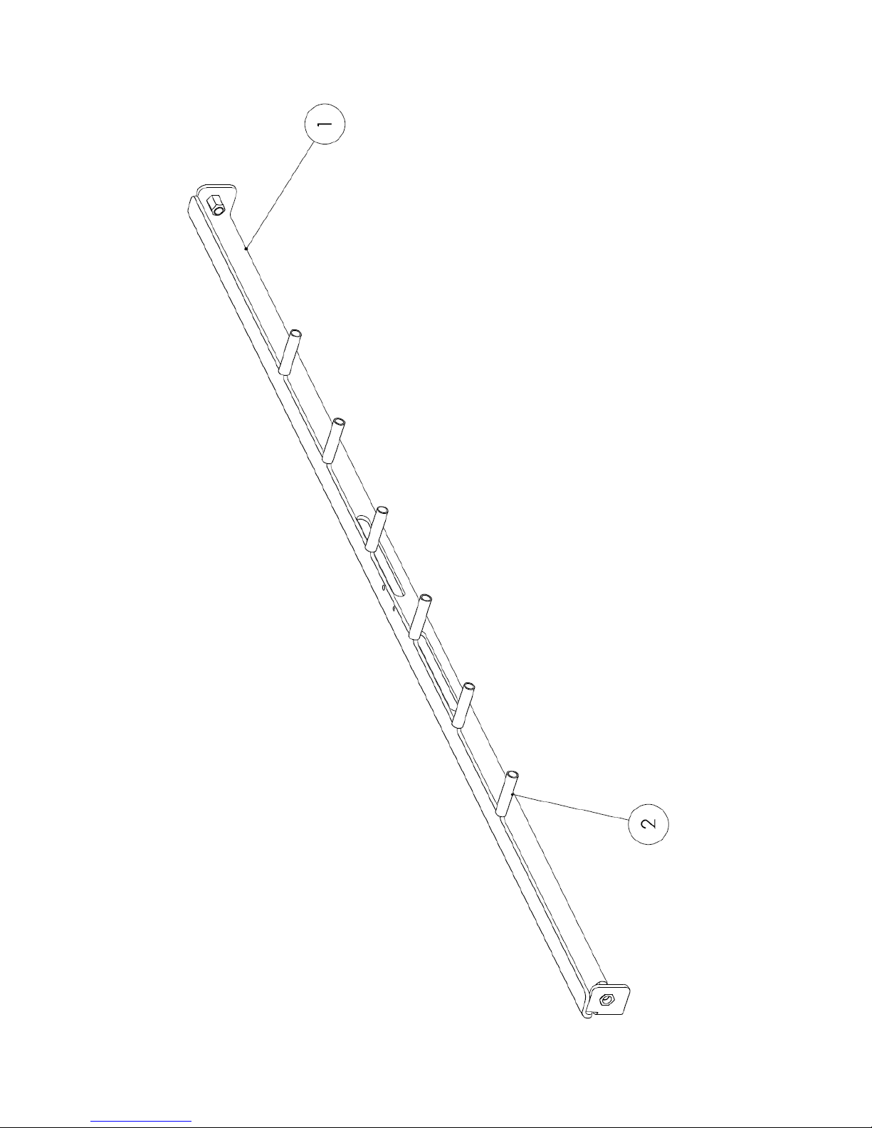
4M05613 BELT GUIDE FT-MAXI
ID Reference Qty Description
1 2T07188 1 Belt guide
2 11-0324 6 Crosspiece
Page 64
FT-M 121 1A 64
Page 65

65 FT-M1211A
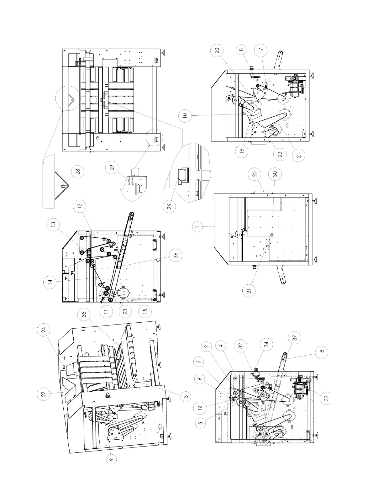
4M05699 TRANSVERSAL MODULE BELTS
ID Reference Qty Description
2 4M05921 5 Motor roller 51x2x120 LG983 B55,5
3 2T07187 1 Table cross
4 10-0354 10 Roller 50x1,5 LG915/905 axle 14xM10
5 4M05922 1 Roller motor 51x2x120 LG 1295 B11 0
6 2D01811 15 Motor spacer plate
7 2T06949 2 Roller support plate
8 10-0557 1 P ulley plate D40
9 2T06955 1 Roller support plate
10 2T06916 1 Counterflange
11 2T07471 1 Sheet metal roll support
12 2C01895 5 Elastic cotton strap stapled W88 LG831
13 2C01896 5 Elastic cotton strap stapled W88 LG925
14 2C01897 5 Elastic cotton strap stapled W88 LG1348
15 2C02515 5 Elastic cotton strap stapled W88 LG2610
16 4M05619 1 Blower tube L=985
17 4M05619 1 Blower tube L=985
18 4M05613 2 Single strap guide
19 16-0883 1 Belt LA40 LG0740-T150
20 16-0881 1 Belt LA40 LG2030-T150
21 16-0882 1 Belt LA40 LG1125-T150
22 16-0880 1 Belt LA40 LG0760-T150
23 16-0883 1 Belt LA40 LG0740-T150
24 2D01848 2 Cylinder support
25 2T06953 1 Belt cover guard
26 15-0162 1 Photocell without reflector
27 2T06952 1 Rear deflector guard
28 15-0034 1 Photocell with reflector
29 11-0320 4 Spacer H10 L55 M6 L10
30 2T06944 1 Electrical casing separation plate
31 2T06990 1 Electric plate
32 2T07294 1 Brace
33 09-0145A 1 Filter regulator
34 09-0145A-V 1 Gate
35 2T07493 2 Rollers rail
36 10-1253 2 Roller 20x1,5 LG866/854 axle RESØ6
37 2T07575 2 Bib cross table
Page 66
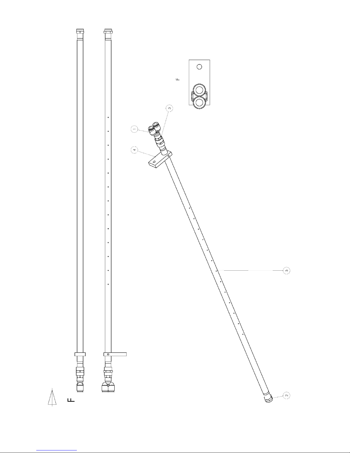
FT-M 121 1A 66
Page 67

67 FT-M1211A
4M05619 TUBULURE OF BLOWING LG985
ID Reference Qty Descri ption
1 14-0885 1 Link auto Y-3/8-10
2 14-0506 1 Link top 3/8F
3 14-0492 1 Link sleeve 3/8F
4 2P03087 1 Sheet metal
5 2D01824 1 Tubulure of blowing
Page 68
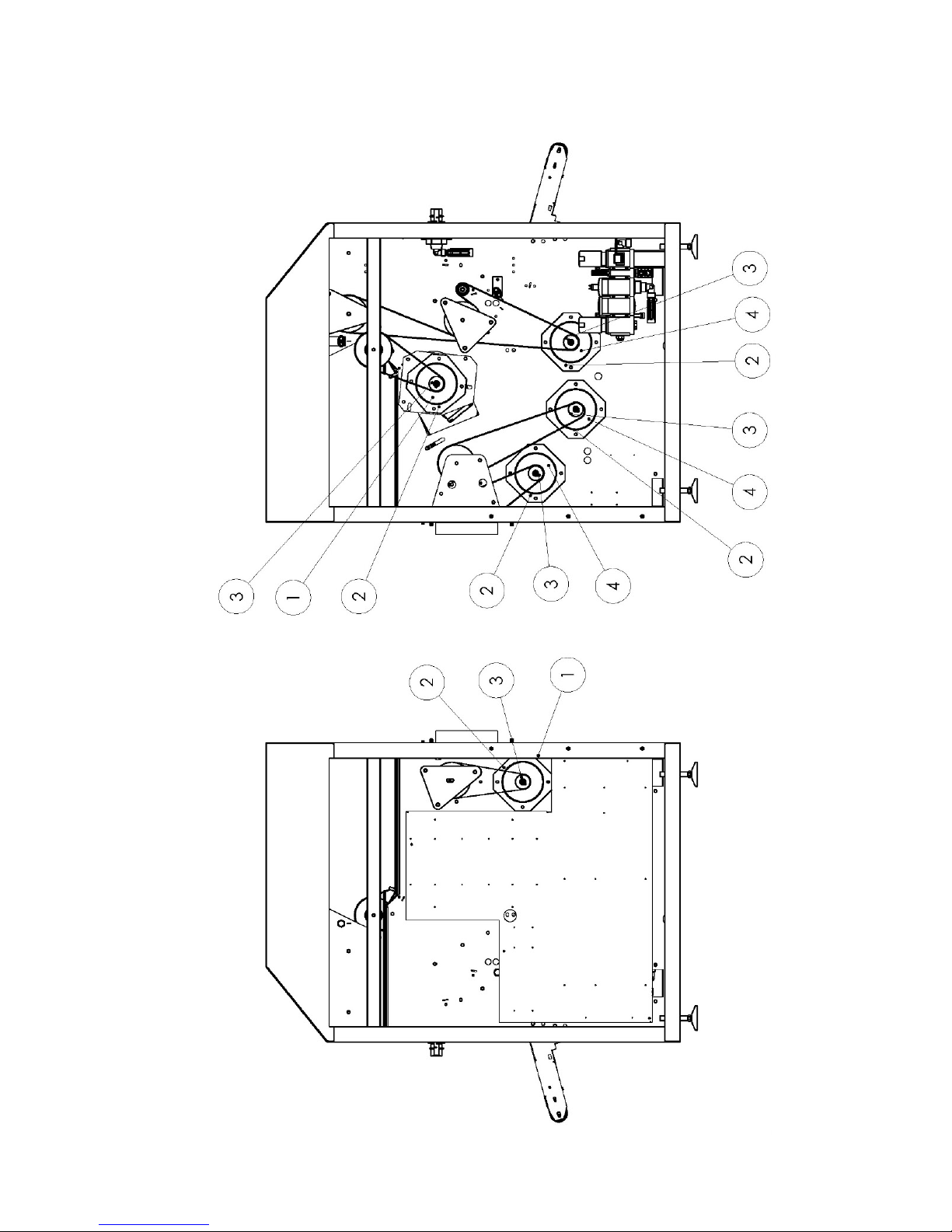
FT-M 121 1A 68
Page 69
69 FT-M1211A
4M05633 CROSS MODULE MOTO L5
4M05633 CROSS MODULE MOTO L6-L7
4M05633 CROSS MODULE MOTO M5-Q5
4M05633 CROSS MODULE MOTO M6-Q6
ID Reference Qty Description
1 10-1278 2 Motor 250W-830TR 208-240V-60Hz/B24V
2 2T07451 5 Motor flange Ø135
3 2D01906 5 Convex alu pulley D40/L59/D19cl
4 10-1279 3 Motor 250W-830TR 208-240V-60Hz
ID Reference Qty Description
1 10-0177 2 Motor 230-400V-50Hz/B24V
2 2T07451 5 Motor flange Ø135
3 2D01812 5 Convex alu pulley D48/L59/D19cl
4 10-0178 3 Motor 250W-680TR 230-400V-50Hz
ID Reference Qty Description
1 10-0402 2 Motor 230-400V-50Hz/B24V
2 2T07451 5 Motor flange Ø135
3 2D01906 5 Convex alu pulley D48/L59/D19cl
4 10-0401 3 Motor 250W-680TR 208V-60Hz
4M05633 CROSS MODULE MOTO Q7-Q9
4M05633 CROSS MODULE MOTO L1
4M05633 CROSS MODULE MOTO Q1
ID Reference Qty Descripti on
1 10-0177 2 Motor 250W-680TR 480V-60Hz/B24V Brake
2 2T07451 5 Motor flange Ø135
3 2D01906 5 Convex alu pulley D48/L59/D19cl
4 10-1176 3 Motor 250W-680TR 480V-60Hz
ID Reference Qty Description
1 10-0177 2 Motor 230-400V-50Hz/B24V
2 2T07451 5 Motor flange Ø135
3 2D01812 5 Convex alu pulley D48/L59/D19cl
4 10-0178 3 Motor 250W-680TR 230-400V-50Hz
ID Reference Qty Description
1 10-1283 2 Motor 250W-830TR-440-480V/60HZ/B24V
2 2T07451 5 Motor flange Ø135
3 2D01906 5 Convex alu pulley D48/L59/D19cl
4 10-1282 3 Motor 250W-830TR 220-240V-60Hz
ID Reference Qty Description
1 10-1281 2 Motor 250W-830TR-440-480V/60HZ/B24V
2 2T07451 5 Motor flange Ø135
3 2D01906 5 Convex alu pulley D48/L59/D19cl
4 10-1280 3 Motor 250W-830TR 440 -480V-60Hz
Page 70
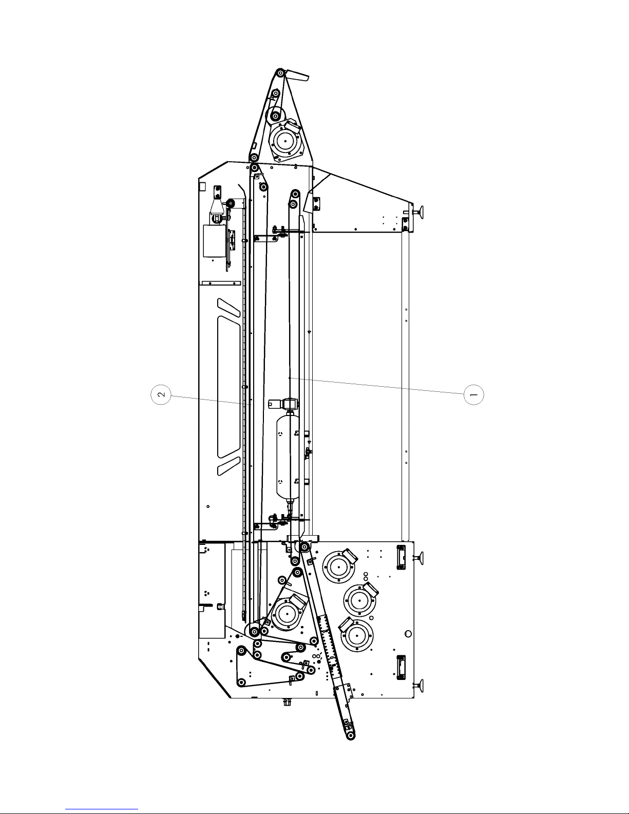
FT-M 121 1A 70
Page 71

71 FT-M1211A
4M05637 LIAISON CROSS + FOLD CONV + FEEDER CONV
ID Reference Qty Description Material
1 2C02514 2 Stapled belt W100/L4760 Felt
2 2C01992 4 Stapled belt W180/L5985 Felt
Page 72
FT-M 121 1A 72
Page 73

73 FT-M1211A
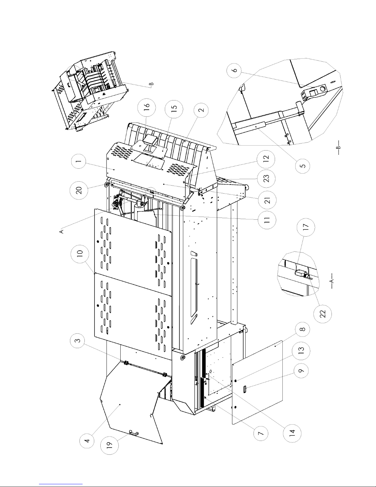
4M05640 CASING
ID Reference Q ty Description
2 2T06881 1 Lower feeder tabl e protection panel
3 12-0217 2 Hinge
4 2S04674 1 Cover guard
5 14-0688 2 Gas cylinder
6 13-0454 1 Security switch
7 16-0065 2 Simple elastic stop D 25 /M8
8 2T07011 2 Cabinet door
9 16-0049 2 Latch handle
10 2T06919 2 Top cover
11 2T06920 2 Central deflector
12 2S04687 1 Front protection guard
13 12-0096 8 Security lock + cam
14 2T06899 2 Cross brace
15 2T07191 1 Operator control console panel
16 SR 1 Production display terminal
17 15-0034 1 Photocell with reflector E3Z
18 13-0454 1 Security switch
19 12-0192 1 Handle
20 11-0406 4 Hoistrings
21 2D01938 1 Ring DE16 DIM8 E5
22 15-0054 1 Connexion part M8 10m
2 3 2T07012 1 Pr otexion sheet metal
Page 74
FT-M 121 1A 74
1
8
2
5
4
6
3
8
Page 75

75 FT-M1211A
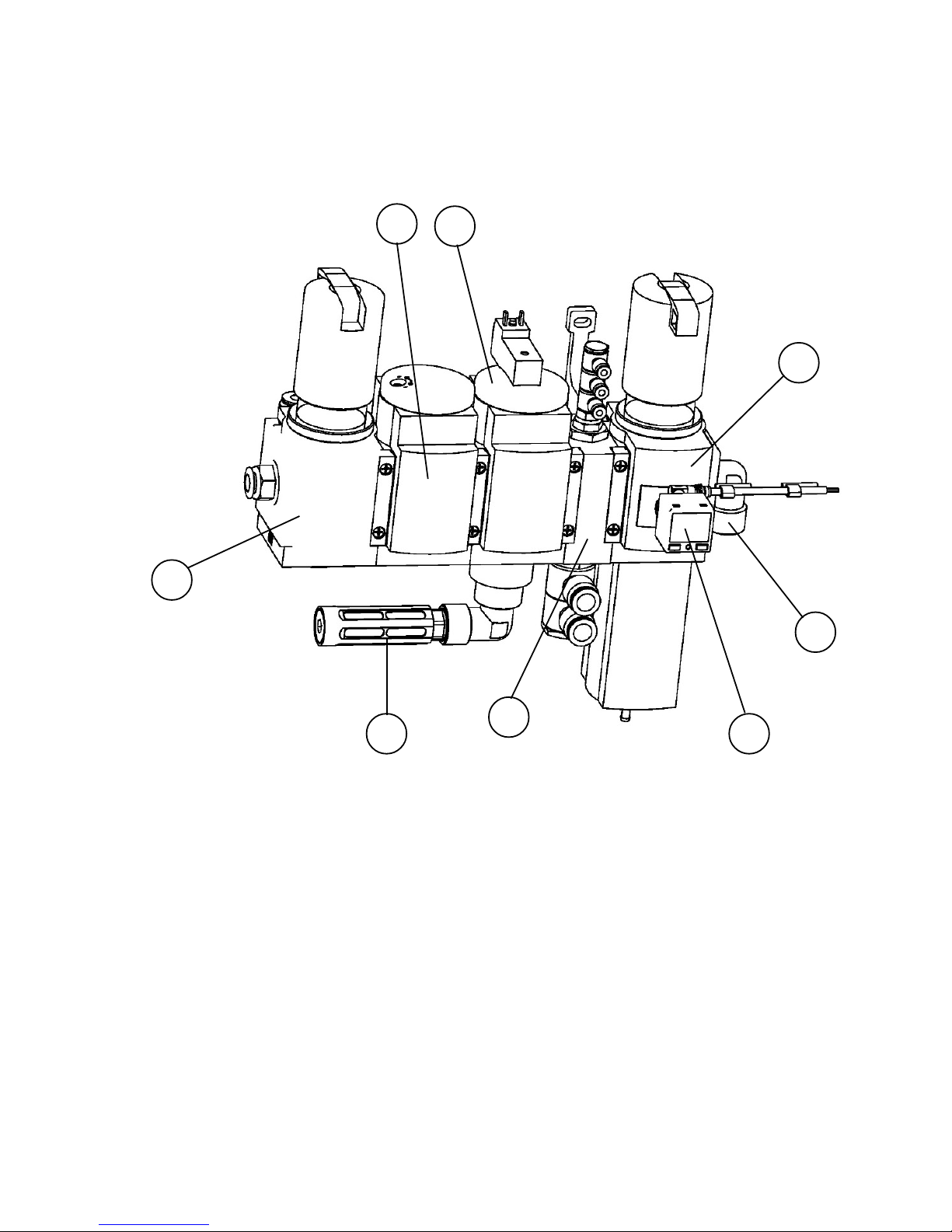
KIT 09-0145 B(PART 2)
ID Reference Qty Descripti on
1 14-1017 1 Distribuidor MS6
2 14-1015 1 Filter MS6-LRB-1/2
3 14-1014 1 Filter MS6-LFR-1/2
4 14-1016 1 Bloc distribuidor MS6
5 14-0568 1 Silencer U-1-1/2B
6 14-1051 1 Pressure captor SPAB-P10R-G18-2P-M8
7 14-0527 1 Link 1/2 - M-F
8 14-1056 1 Distributor MS6-DL-1/2-Z
Page 76
FT-M 121 1A 76
Page 77
77 FT-M1211A
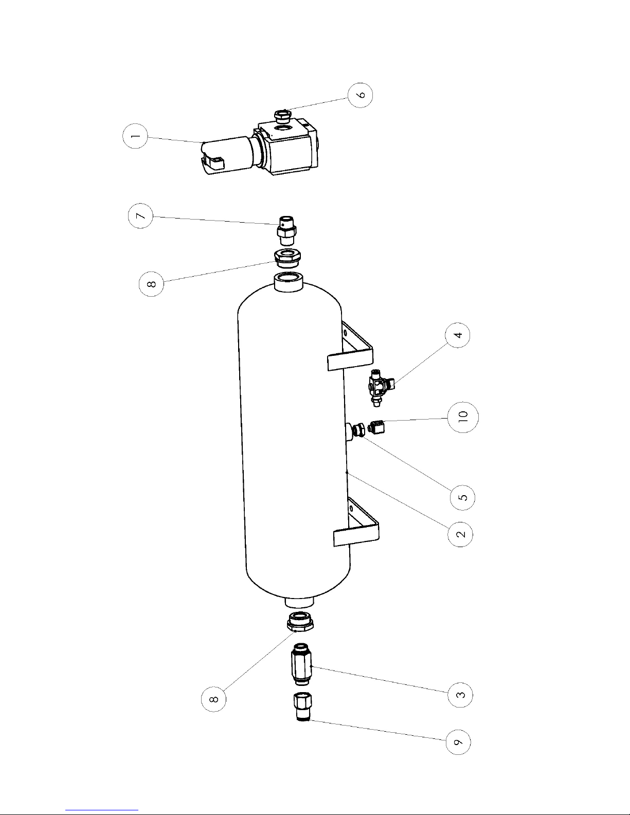
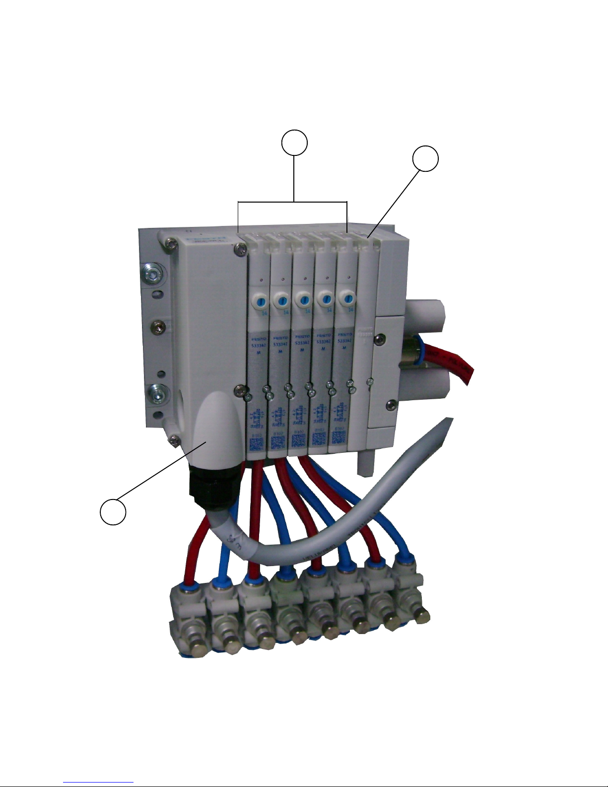
KIT 09-0147 A
KIT 09-0165 A
ID Reference Qty Descripti on
1 14-0887 1 Pressure regulator MS6-LR-1/2 -D6
2 14-0179 1 Tank 10L
3 14-0082 1 Valve 1/2
4 14-0084 1 Valve
5 14-0471 1 Link reduction 3/8M-1/8F
6 14-0473 1 Link reduction 1/2M-3/8F
7 14-0479 1 Link 1/2 M
8 14-0875 2 Link reduction 1M-1/2F
9 14-0989 1 Link auto F1/2-10/12
10 14-0524 1 Link 1/8M-F
Page 78
FT-M 121 1A 78
4
6
5
Page 79
79 FT-M1211A
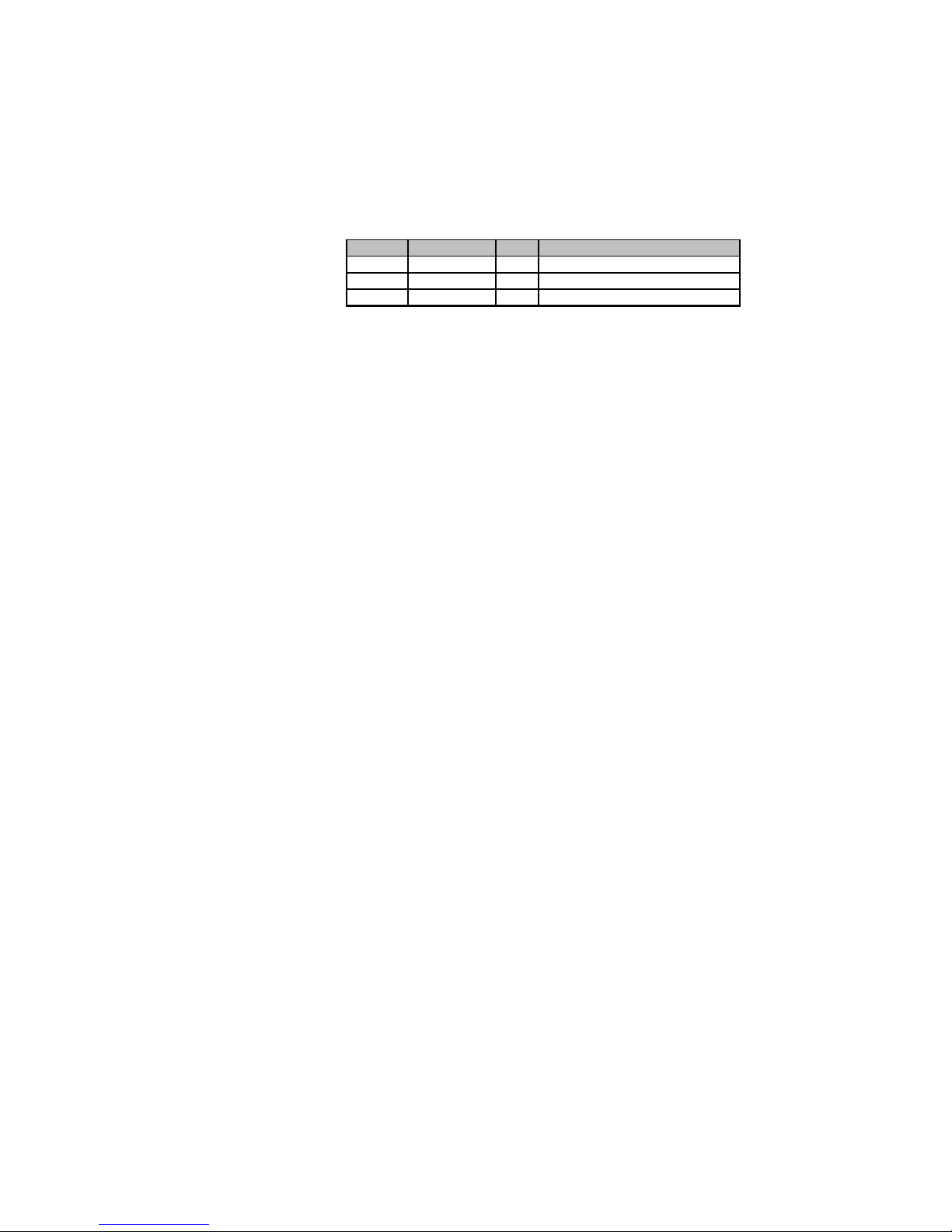
KIT 09-0148A
ID Reference Qty Descri ption
4 14-0969 3 Iron sheet meta l VMPA
5 14-0966 5 Electrodistribuidor VMPA 5/2
6 14-0988 1 Cable connexion VMP ALSO B24
Page 80
FT-M 121 1A 80
1
3
4
2
5
1
14-0184
Page 81
81 FT-M1211A
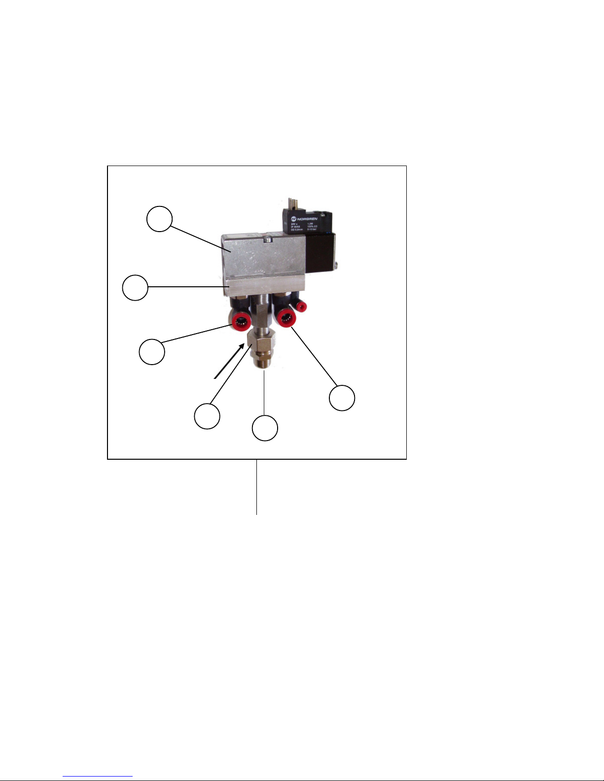
KIT 09-0124F
ID ID Reference Qty Description
1 14-0426 2 Link auto 1/4 - 8/10
2 2P02834 1 Base distributor
3 14-0962 2 Link ring + nut 3/8 tube 14
4 2D01652 1 Link
5 14-1456 1 Distributor
15-0073 5 NR 10m Cable co nnexion part EV type C
14-0184 4
Page 82
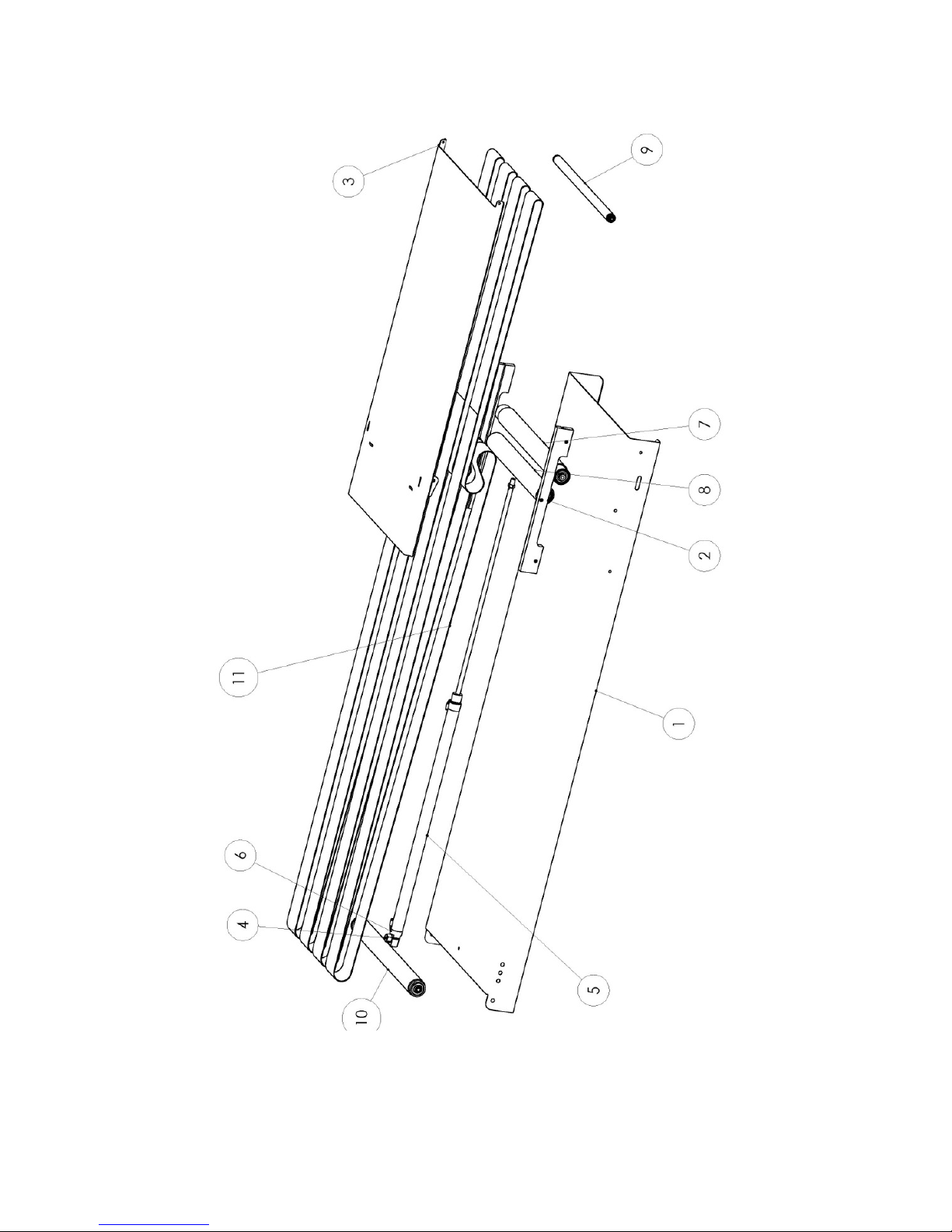
FT-M 121 1A 82
Page 83
83 FT-M1211A
4M05631 SHUTTLE LU450
4M05644 SHUTTLE LU450
KIT 09-0146A
4M05646 SHUTTLE LU450 - STRAPS
ID Reference Qty Descri pti on
11 2C01902 4 Felt strap stapled W60 - L4100
ID Reference Qty Description
5 14-0819 1 Strut cylinder D25-C500
6 14-0429 2 Elbow connector auto M5_4-6
ID Reference Qty Descri pti on
1 2T06897 1 Shuttle base LU0 450
2 2 C01901 2 Shu ttle slide LU6 15
3 3S0 1567 1 Shuttle nose U
4 2D01847 1 Axle 6 Pans-17 W32-D8L19-M6
5 14-0819 1 Cylinder D25-C500
6 14-0429 2 Link auto M5-4-6
7 3D00856 1 Unidirectional roller W=435
8 3D00857 1 Unidirectional roller W=365
9 10-1222 1 Roller 20x1.5 W411/406 Axle 08xM5
10 10-0356 1 Roller 40x1.5 W445/435 Axle 12xM8
11 2C01902 4 Stapeld felt belt LA60-LG4100
Page 84
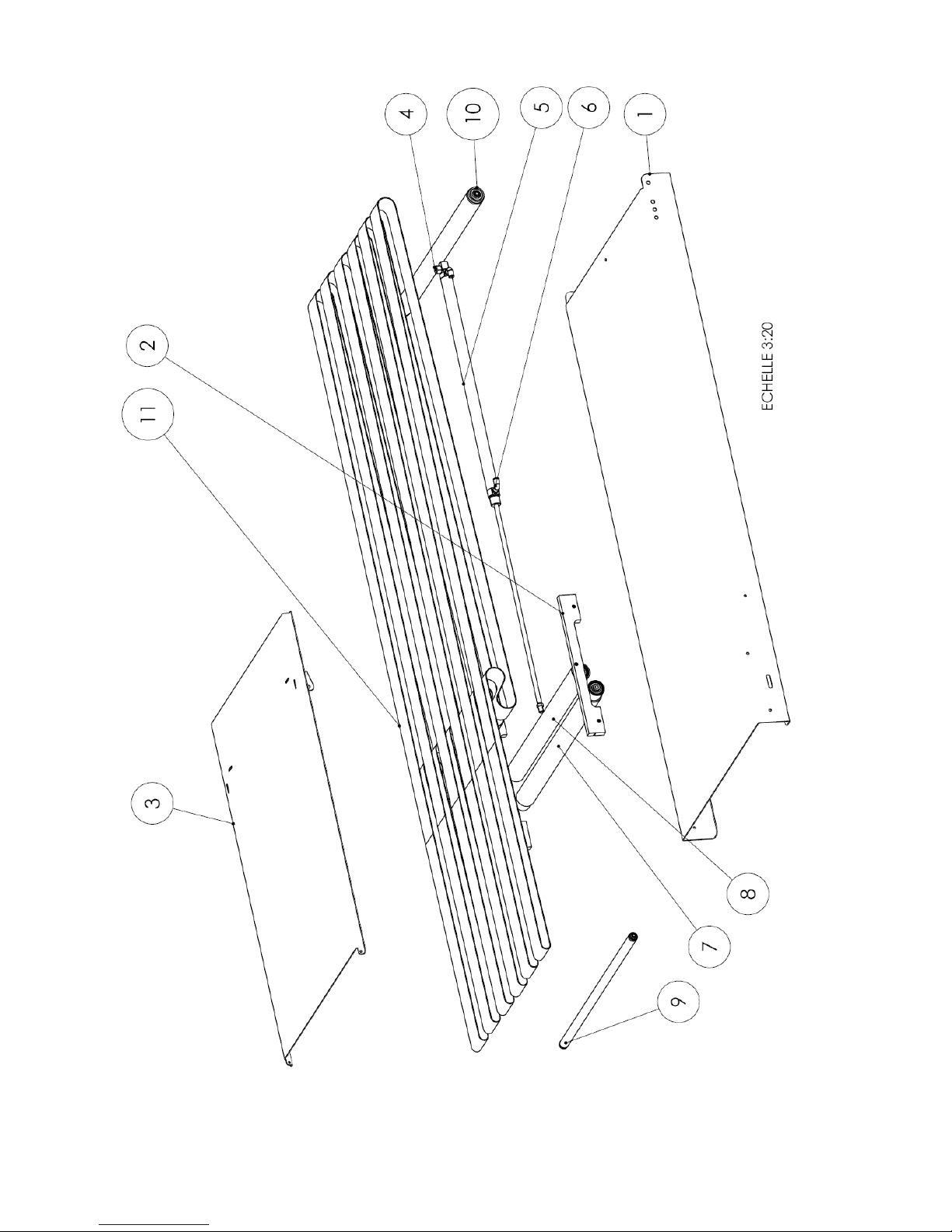
FT-M 121 1A 84
Page 85
85 FT-M1211A
4M05601 SHUTTLE LU615
4M05636 SHUTTLE LU615 - STRAPS
4M05644 SHUTTLE LU450
KIT 09-0146A
ID Reference Qty Descripti on
11 2C01902 6 Felt strap stapled W60 - L4100
ID Reference Qty Description
5 14-0819 1 Strut cylinder D25-C500
6 14-0429 2 Elbow connector auto M5_4-6
ID Reference Qty Description
1 2T06907 1 Shuttle base LU615
2 2C01901 2 Shuttle slide LU615
3 3S01572 1 Shuttle nose LU615
4 2D01847 1 Axle 6 Pans-17 W32-D8L19-M6
5 14-0819 1 Cylinder D25-C500
6 14-0429 2 Link auto M5 4-6
7 3D00850 1 Unidirectional roller LU=600
8 3D00851 1 Unidirectional roller LU=530
9 10-1221 1 Roller 20x1.5 L576/571 AXLE08xM5
10 10-0347 1 Roller 40x1.5 L610/600 AXLE 12xM8
11 2C01902 6 Stapled felt belt LA60-LG4100
Page 86
FT-M 121 1A 86
Page 87
87 FT-M1211A
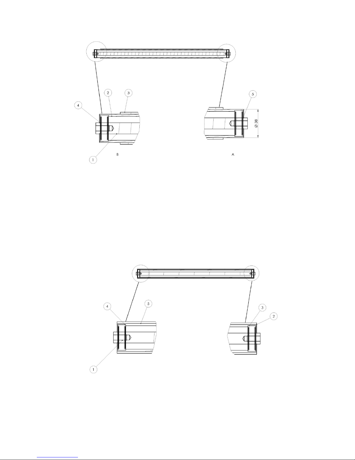
4M05923 UNIDIRECTIONAL ROLLER LU=600
4M05924 UNIDIRECTIONAL ROLLER LU=530
ID Reference Qty Description
1 2D01850 1 Axle D15 L610
2 2D018 51 1 Tube D38/L600
3 16-0021 D38 0545 1 Drum covering auto W50 rough grey
4 10-0312 1 Bearing 15x35x11
5 10-1216 1 Bearing 15x35x11 free wheel
ID Reference Qty Description
1 2D01852 1 Axle D15 L610
2 2D01851 1 Tube D38/L600
3 16-0021 D38 0545 1 Drum covering auto W50 rough grey
4 10-0312 1 Bearing 15x35x11
5 10-1216 1 Bearing 15x35x11 free wheel
Page 88
FT-M 121 1A 88
Page 89
89 FT-M1211A
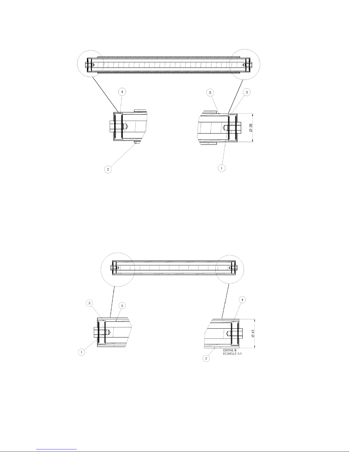
4M05925 UNIDIRECTIONAL ROLLER LU=435
4M05926 UNIDIRECTIONAL ROLLER LU=365
ID Reference Qty Description
1 2D01834 1 Axle D15 L445
2 2D01853 1 Tube D38/L435
3 16-0021 D38 0545 1 Covering spur white W50
4 10-0312 1 Bearing 15x35x11
5 10-1216 1 Bearing 15x35x11 free wheel
ID Reference Qty Description
1 2D01836 1 Axle D15 L375
2 2D01837 1 Tube D38/L365
3 16-0021 D38 0545 1 Covering spur white W50
4 10-0312 1 Bearing 15x35x11
5 10-1216 1 Bearing 15x35x11 free wheel
Page 90
FT-M 121 1A 90
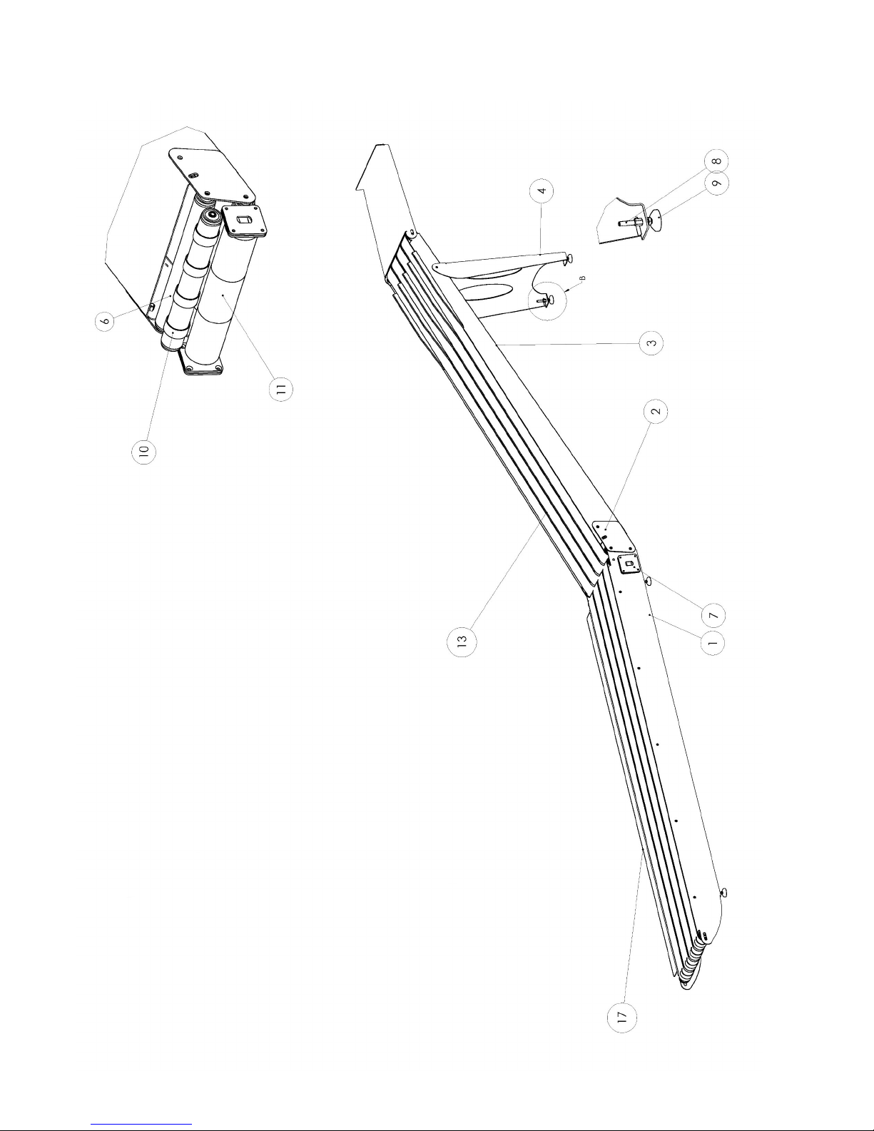
Page 91
91 FT-M1211A
4M05947 DISCHARGE CONVEYOR
ID Reference Qty Description
1 2T06903 1 Common discharge conveyor frame
2 2T07702 2 Discharge conveyor liaison tie spacer
3 2T06902 1 Upper discharge conveyor frame
4 2T06901 1 Discharge conveyor base support
6 10-0363 3 Roller 50x1.5 L436/426 axle 14xM10
7 2T06905 6 Discharge conveyor clearance
8 12-0397 6 Foot bolt M8x60xD10
9 12-0396 6 Foot base PA D40 D10
10 4M05994 1 R oll 50x1,5 LG 43 6/ 42 6 Axle 14xM10 with rings
11 10-1209 1 R oller motor 440/400/75W/0.6M/S
13 2C01990 5 Felt strap stapled 88MM - L8180
14 2T03557 1 Cell support E3Z
15 15-0162 1 Cell
16 15-0 054 1 Connexion part M8 10m
17 2T07701 1 Protection sheet metal
4M05634 DISCHARGE CONVEYOR L5-L6-L7
4M05634 DISCHARGE CONVEYOR M5-M5/M6-M6
4M05634 DISCHARGE CONVEYOR Q5-Q5/Q6-Q6-Q7-Q8-Q9
ID Reference Qty Descripti on
11 10-1065 1 Cylindrical roller motor D80/R L412 220-230-240V/50-60HZ/85W/0,6M
ID Reference Qty Descri ption
11 10-1209 1 Cylindrical roller motor D80/RL412 380-400-420-440-460-480VV50-60Hz
4M05634 DISCHARGE CONVEYOR L1
ID Reference Qty Descri ption
11 10-1271 1 Cylindrical roller motor D80/RL412 208-240V/60HZ/85W/0,72M/SZ ULCSA
ID Reference Qty Descri ption
11 10-1210 1 Cylindrical roller motor D80/RL412 200-208V/50-60HZ/85W/0,6M/SZ
4M05634 DISCHARGE CONVEYOR Q1
ID Reference Qty Descri ption
11 10-1270 1 Cylindrical roller m otor D80/RL412 440-480W/60H Z/120W/0,72M/SZ ULCSA
Page 92
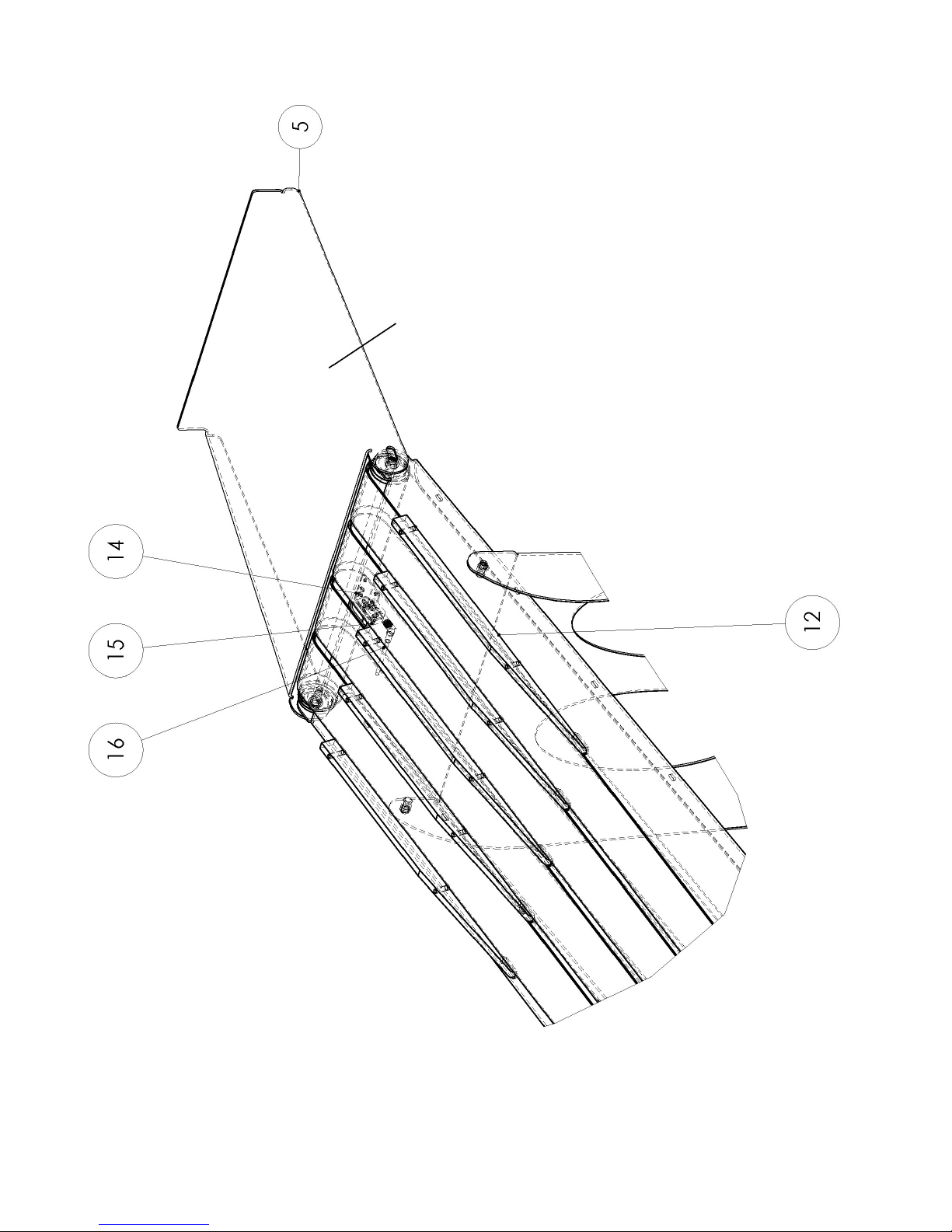
FT-M 121 1A 92
Page 93
93 FT-M1211A
4M05977 STORAGE TRAY OPTION
ID Reference Qty Description
5 2T06900 1 Discharge conveyor storage tray
12 2C01934 5 Conveyor fingers
15 15-0162 1 Photocell E3Z-LS86
16 15-0190 1 M8 right 10m
14 2T03557 1 Cell support E3Z
Page 94
FT-M 121 1A 94
1
2
3
Page 95

95 FT-M1211A
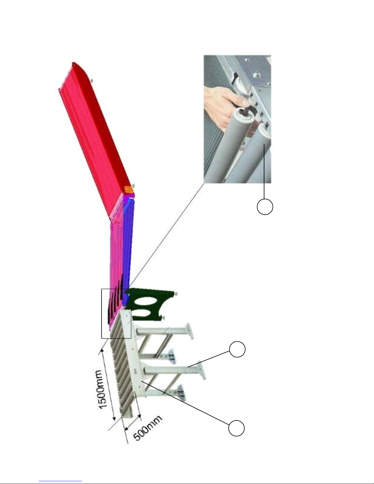
4M05749 CONVEYOR WITH FREE ROLLS OPTION
ID Reference Qty Description
1 4M00964 1 Free roll 1500x53
2 4M01236 1 Height free roll 460-940
3 4M04337/530 1 Roll LA530
NR 1 5-0034 1 Photocell E3Z
NR 15-0048 1 Reflector
NR 1 5-0190 1 Connexion part M8 right 10 m
NR 2T03144 1 Reflector support 60x90
NR 2T0 3557 1 Cell support E3S
NR 4M01239 1 Buffer D530mm
Page 96

FT-M 121 1A 96
 Loading...