

GHZ 1214-30 Datasheet
1214-30
30 Watts, 28 Volts, Pulsed
Radar 1200 - 1400 MHz
GENERAL DESCRIPTION CASE OUTLINE
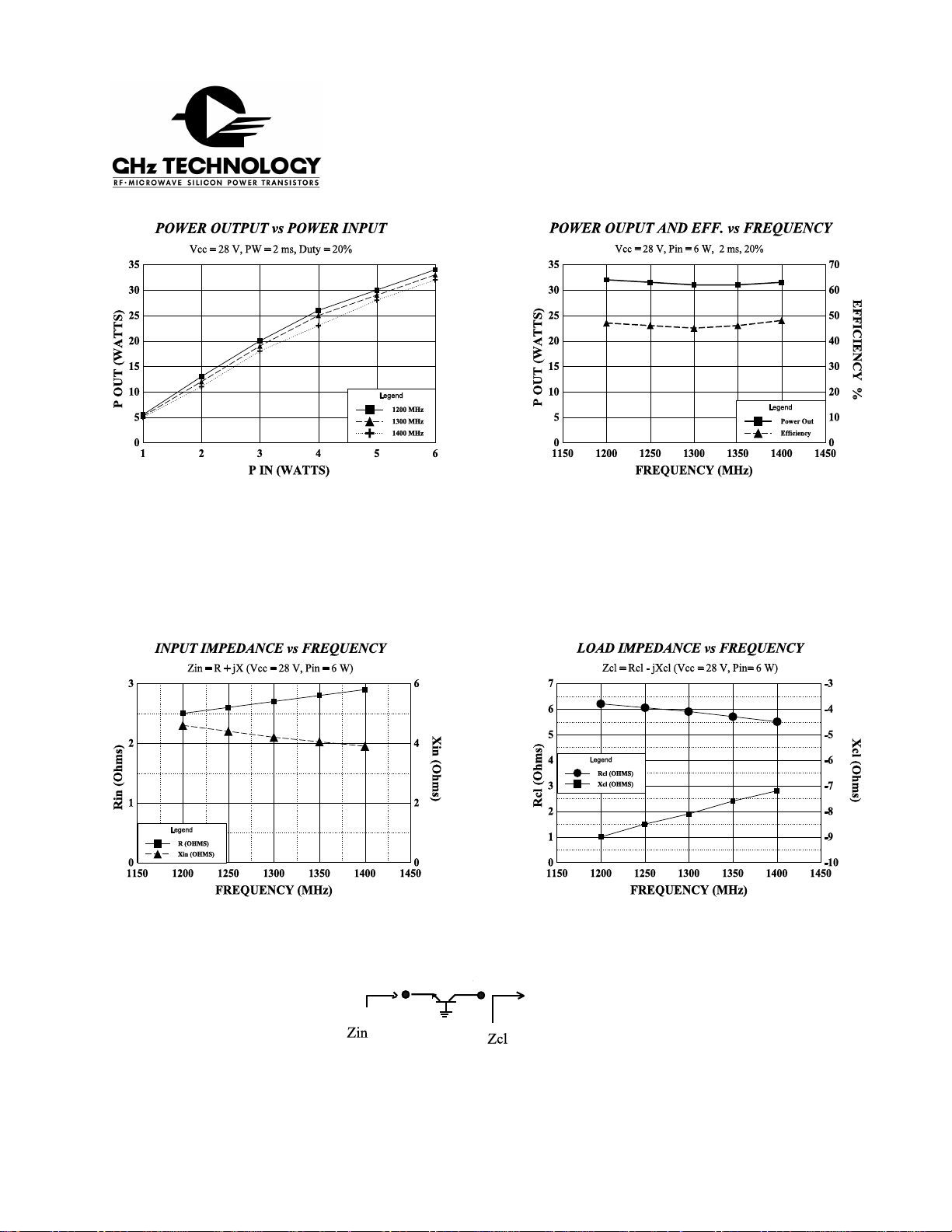
The 1214-30 is an internally matched, COMMON BASE transi stor capable of
providing 30 Watts of pulsed RF output power at two milliseconds pulse
width, twe nty p ercent duty fac tor across the b and 1200 to 1400 MHz. This
hermetically solder-sealed transistor is specifically designed for long pulse
radar applications. It utilizes gold metalization and diffused emitter ballasting
to provide high reliability and supreme ruggedness.
55AW, STYLE 1
ABSOLUTE MAXIMUM RATINGS
Maximum Power Dissipation @ 25 C 88 Watts
Maximum Voltage and Current
BVces Collector to Emitter Voltage 50 Volts
BVebo Emitter to Base Voltage 3.5 Volts
Ic Coll ecto r Current 4.0 Amps
Maximum Temperatures
Storage Temperature - 65 to + 200 C
Operating Junction Temperature + 200 C
ELECTRICAL CHARACTERISTICS @ 25 C
SYMBOL CHARACTERISTICS TEST MIN TYP MAX UNITS
Pout
Pin
Pg
η
c
VSWR
Powe r Out F = 1200-1400 MHz 30 Watts
Powe r Input Vcc = 28 Vo lts 6.0 Watts
Power Gain Pulse Width = 2 ms 7.0 dB
Collector Efficien cy Duty = 20% 48 %
Load Mismatch Tolerance Rated Conditions 3:1
o
o
o
O
CONDITIONS
BVces
BVebo
Hfe
Cob
θ
jc
* Not measureable due to internal prematch network
IssueA July 1997
GHz TECHNOLOGY INC. RESERVES THE RIGHT TO MAKE CHANGES WITHOUT FURTHER NOTICE. GHz RECOM M E NDS THAT BEFORE
TH E PRODUCT(S) DESCRIBED HEREIN ARE WRITTEN INTO SPECIFICATIONS, OR USED IN CRITICAL APPLICATIONS, THAT THE
PERFORMANCE CHARACTERISTICS BE VERIFIED BY CONTACTING THE FACTORY.
GHz Technology Inc. 3000 Oakm ead Village Drive, Santa Clara, CA 95051-0808 Tel. 408 / 986-8031 Fax 408 / 986-8120
Collector to Emitter Breakdown Ic = 50 mA 50 Volts
Emitter to Base Breakdown Ie = 5 mA 3.5 Volts
DC Curre nt Gain Vce=5 V, Ic =500mA 20
Output Capacitanc e* F=1 MHz, Vcb=28V pF
Thermal Resistance Rated Pulse Condition 2.0 C/W
o
1214-30
Typical Impedances
August 1996
 Loading...