

Page 1
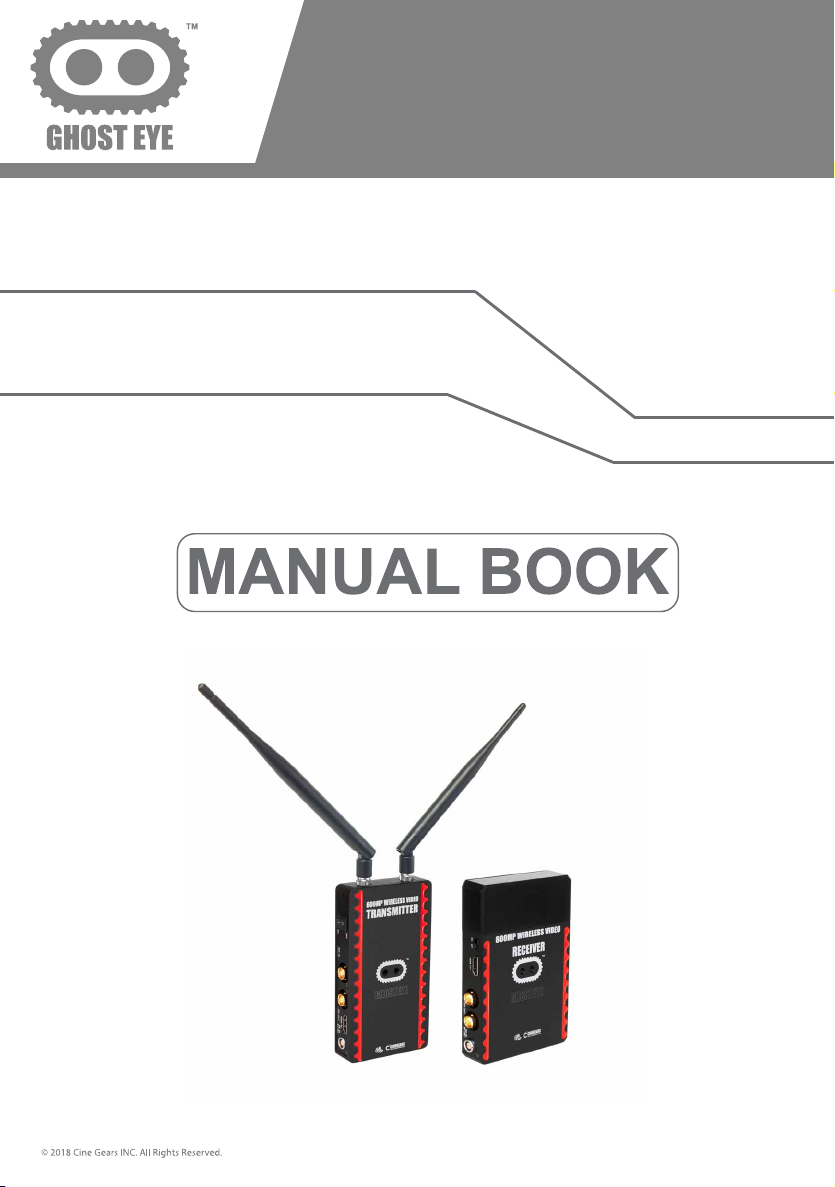
600M PLUS WIRELESS
VIDEO TRANSMISSION SYSTEM
Page 2
Page 3
About the 600M Plus Wireless Video Transmission System 1
Foreword 1
Brief Introduction 1
Features 1
Structure & Interface
Installation
LCD Screen 11
Supports full PSF resolutions 13
Trouble Shooting 14
Disclaimers 15
About Cinegears 17
2Specification
3
7
Page 4
Foreword
Please read this manual carefully before you use this product retain it properly for future
reference.
If there is any doubt or difficulty in the process of product usage, please feel free to contact
us or the dealer.
The company reserves the authority to amend the specification.
Brief Introduction
As the widely use of live broadcasting, there is some problem existing in the process of cable
wiring, such as the high cost and short-life usage of the cable. Also, the cable trod by the crowd
under insufficient site protection is the major cause of cable performance, even lead to the live
broadcast accident. We provide you with more convenient and safer solution for live
broadcasting. The long distance transmission system applied with high-capacity Li-battery, plugand-play setting, can fully meet requirement of outdoor and indoor shooting. Especially, no cable
wiring will bring the safer and more professional experience to you!
Features
Effective range up to 300M, suitable for film shooting, live broadcast, wedding and big
conference use.
Support 1080P/60Hz 4:2:2bit, uncompressed real time HD video transmitting.
Support HDMI/HD-SDI/3G-SDI.
Plug&Play - easy to install.
Support channel switching and broadcasting mode for 1transmitter to multiple receivers.
Compatible EDID 1.1, support HDMI 103 (1.4 3D, optional).
AES128/256 Encryption.
1
Page 5
Specification
Supported
1080psf 23.98/24/25
Supported
Socket; Power ON/OFF
Power ON/OFF
Specification
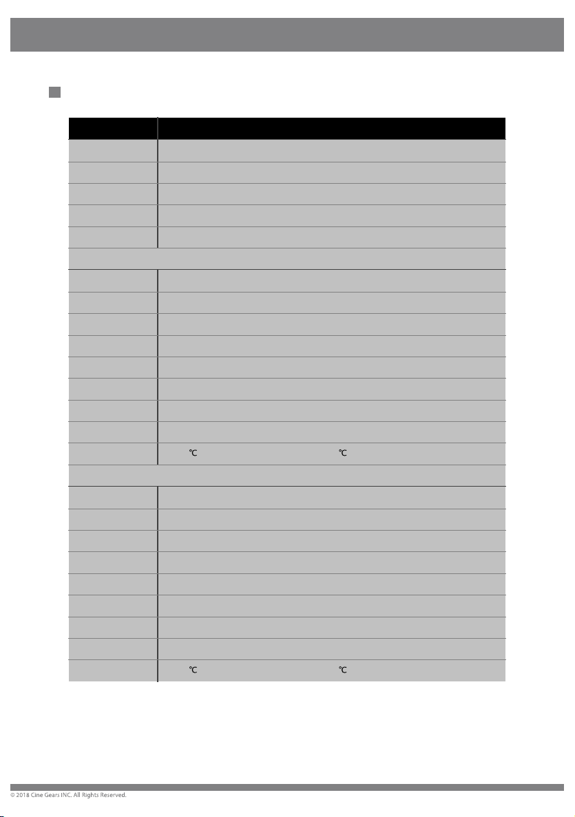
ITEM Specification
Frequency 5.1-5.9(GHz)
Bandwidth 40MHz
Video Formats
Audio Formats
transmission range 300m(MAX)
Antenna External Antenna x 2 pcs
Transmission power 18dbm
Functional Interface
Locating Structure 1/4” Hot-shoe connection
LCD Screen Wireless Channel Info; SDI/HDMI Signal Info; Fan info
Working Voltage 9V-18V
Power Consumption 9W
Dimensions 142.5 x 76 x 24.3 mm
Temperature
Antenna Internal Antenna x 5pcs
Receiving sensitivity -70dBm
Functional Interface
Locating Structure 1/4” Hot-shoe connection; V-Mount
LCD Screen Wireless Channel Info; SDI/HDMI Signal Info
Working Voltage 9V-18V
Power Consumption 7-8W
Dimensions 141 x 100 x 22.4 mm
Temperature -10~60
1080p 23.98/24/25/30/50/60
PCM, DTS-HD, Dolby TrueHD
Transmitter
HDMI Input; SDI Input; SDI Loop Output; Mini USB; LEMO Power IN; Antenna RPSMA
-10~60
(operating) 10%-90% humidity; -40~80 (storage) 10%-90% humidity.
Receiver
SDI Dual Output; HDMI Output; Mini USB; LEMO Power IN; Antenna RPSMA Socket;
(operating) 10%-90% humidity; -40~80 (storage) 10%-90% humidity.
*Since the product’s improving process, all the performance, design and specifications of our products are subject to
minor change without prior notice.
2
Page 6
Structure & Interface
Structure & Interface
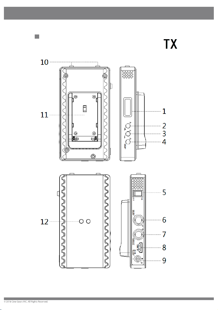
Transmitter 600MP
3
Page 7
Structure & Interface
our
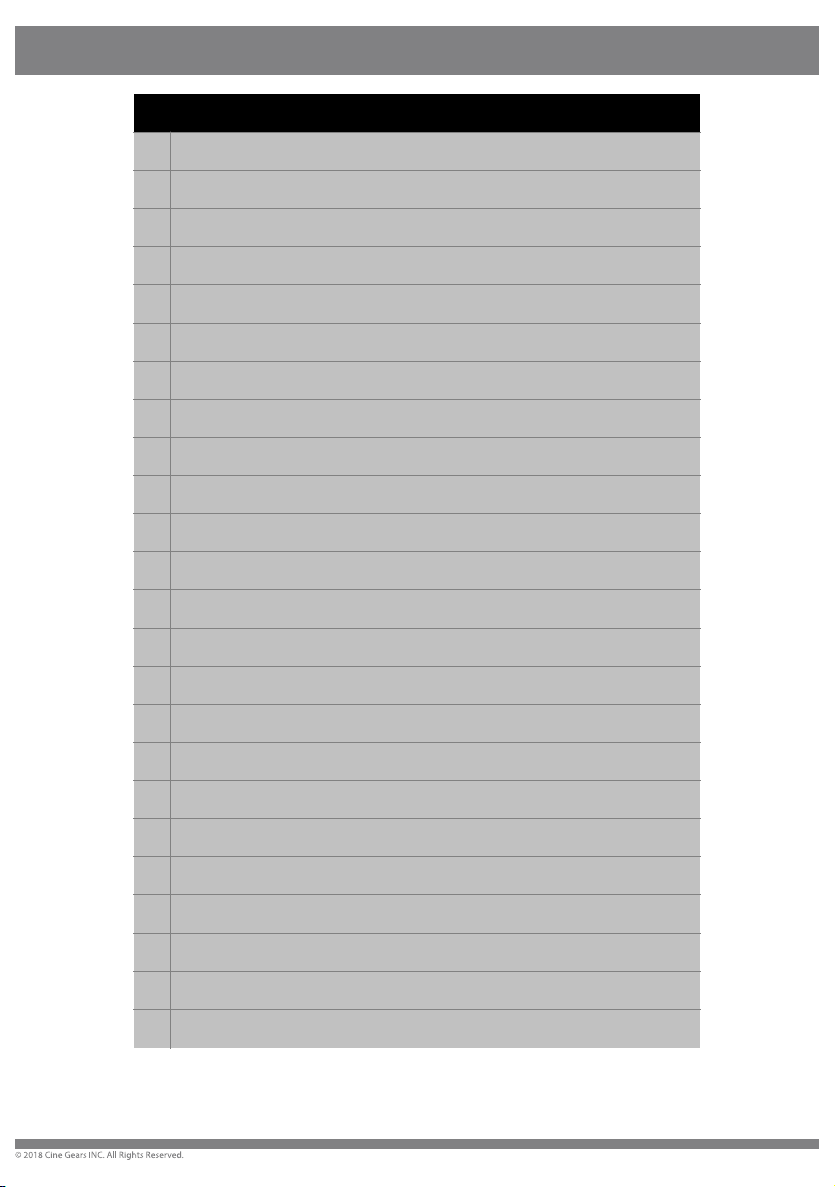
1 LCD Screen
Display the information about the Channel, signal input, capacity, temperature.
2 UP
Select the correct Channel.
3 DOWN
Select the correct Channel.
4 MENU
Unlock the screen and confirm the selection.
5 Power ON/OFF
Power ON/OFF
6 SDI IN
Connect the HD camcorder which support 3G-SDI, HD-SDI
7 SDI OUT (Loop)
Structure
Connect to the HD digital monitor which support 3G-SDI, HD-SDI
8 HDMI IN
Connect to the HD digital camcorder with HDMI OUT
9 Power supply In (Lemo)
Support connecting to the power supply of the camera, or power adaptor.
10 Antenna Socket
SMA socket to connect the antenna.
11 Battery Clip
Support SONY F970/F550 battery to power supply.
12 1/4” Hot-shoe Connection
Support to connect with more methods.
*Since the product’s improving process, all the performance, design and specifications of
products are subject to minor change without prior notice.
4
Page 8
Structure & Interface
Structure & Interface
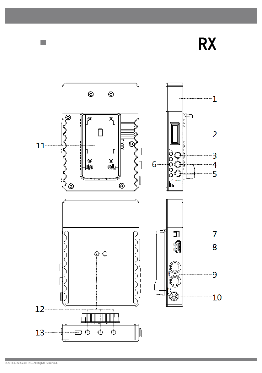
Receiver 600MP
8
5
Page 9
Structure & Interface
1 Antenna
Built-in Antennas.
2 LCD Screen
Display the information about Channels, signal input, capacity, temperature.
3 UP
Select the correct Channel.
4 DOWN
Select the correct Channel.
5 MENU
Unlock the screen and confirm the selection.
6 RSSI Status Display
Signal Strength
Structure
7 Power ON/OFF
Power ON/OFF
8 HDMI OUT
Connect to the TV/Monitor via the HDMI cable.
9 SDI OUT
Connect to the TV/Monitor via the HDMI cable.
10 Power supply In (Lemo)
Support connecting to the power supply of the camera, or power adaptor.
11 Battery Clip
Support SONY F970/F550 battery to power supply.
12 1/4 Hot-shoe Connection
Support to connect with more methods.
6
Page 10
13 Mini USB
For firmware upgrade use.
*Since the product’s improving process, all the performance, design and specifications of our
products are subject to minor change without prior notice.
Installation
For Transmitter
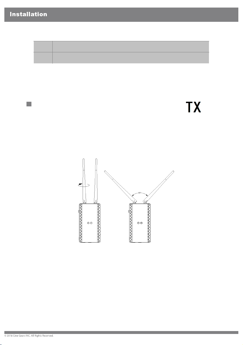
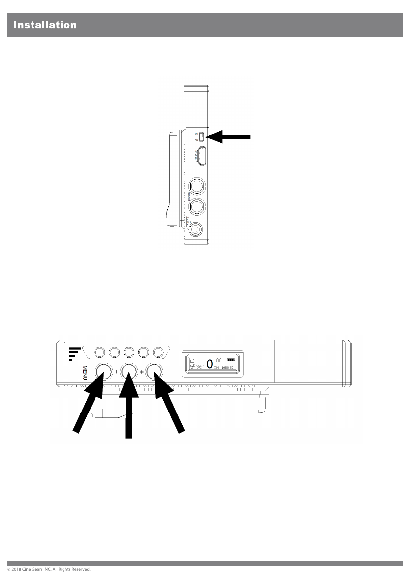
1.Fix the antennas to the transmitter, and arrange them to be right angle as
figured below
.
7
Page 11
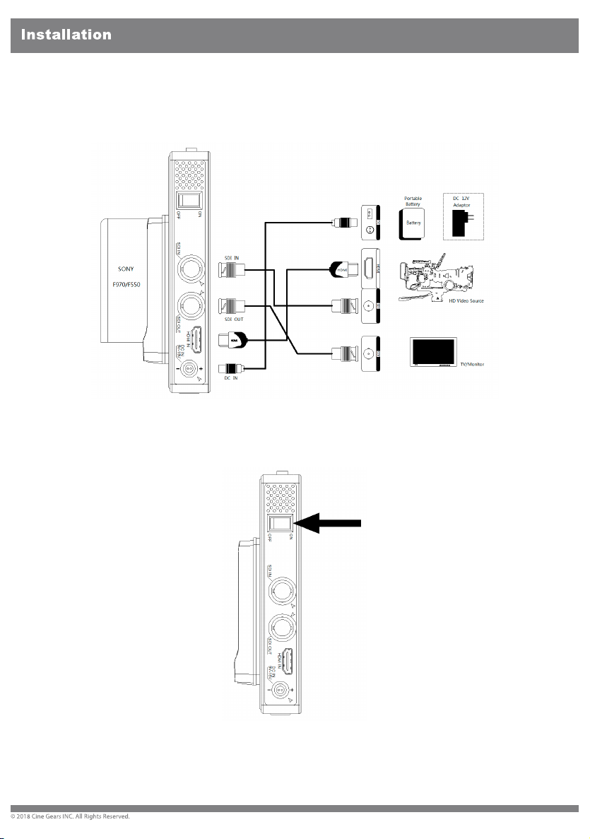
2.Connect the transmitter to the power supply via the certail power
cable
HD
or SONY F970/F550 battery. Connect the SDI/HDMI cable to the
video source.
3.Turn ON the power supply and make sure the transmitter strat to work.
8
Page 12
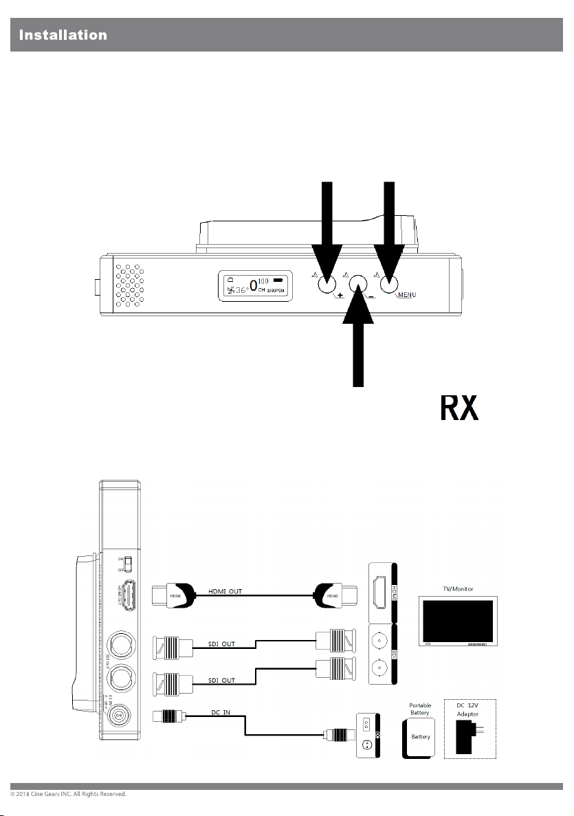
4.Long press the “MENU” button to unlock the screen and then press
“+”
will
or
or “-” button to select the wireless channel that corresponding to the
Receiver, then press the “MENU” button to comfirm.
When the video signal is normally transferred, the LCD screen
display “video”.
For Receiver
1.Connect the Receiver to the power supply via the certain power cable
battery. Conect the SDI/HDMI cable to the TV/Monitor.
12
9
Page 13
2.Turn ON the power supply and make sure the receiver start to work.
“+”
the
display
3. Long press the “MENU” button to unlock the screen and then press
or “ - ” button to select the wireless channel that corresponding to
Transmitter, then press the “MENU” button for confirm.
When the networking is normally connected, the RSSI lights will
signal strength.
10
Page 14
LCD Screen
LCD Screen
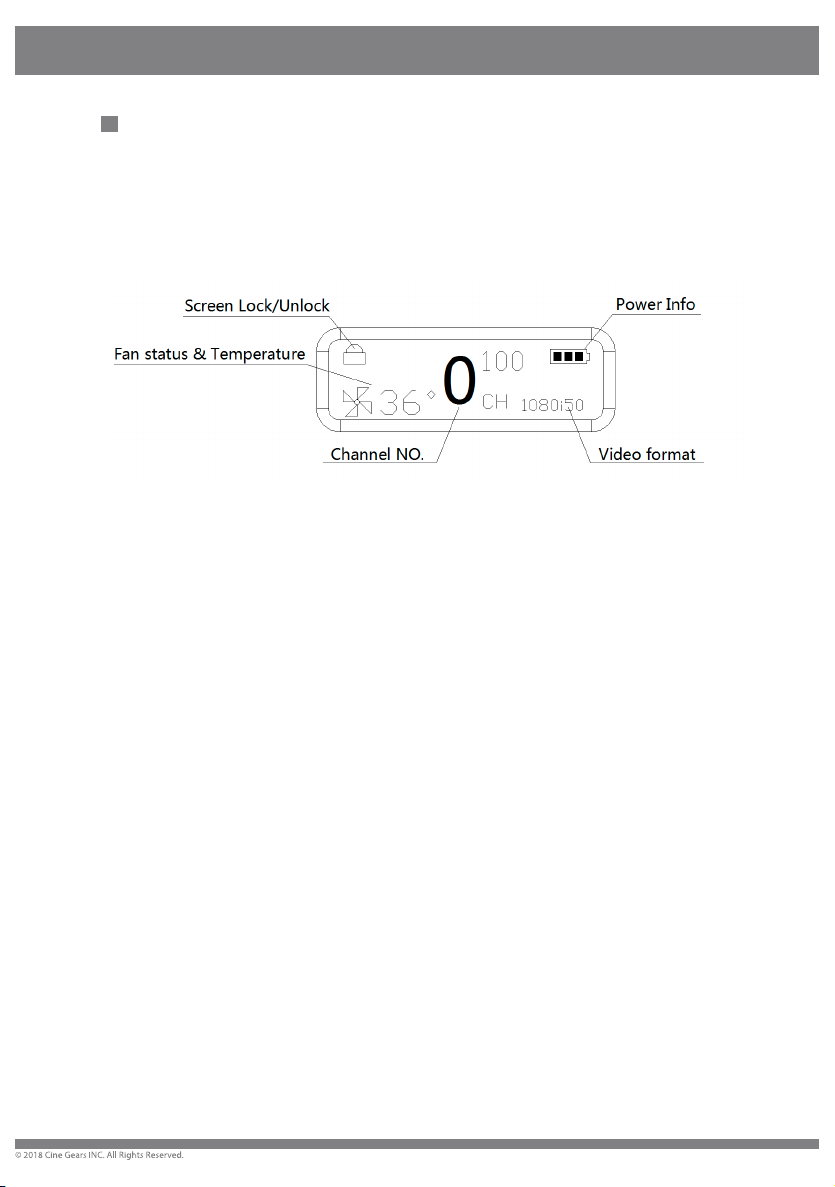
600MP Transmitter LCD Screen
Screen Lock/Unlock : The screen will be always locked unless long press
the MENU button to unlock.
Power Info : Display the current power supply status.
Channel NO. : Display the current Channel NO. of device.
Video format : Display the video source format.
Fan status & Temperature : Display the ventilation fan running status and
inside temperature.
11
Page 15
press
and
LCD Screen
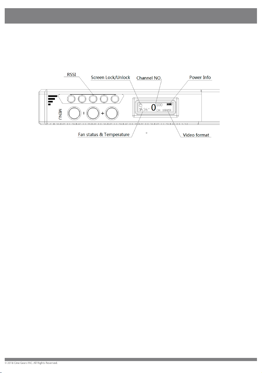
600MP Receiver LCD Screen
Screen Lock/Unlock : The screen will be always locked unless long
Power Info : Display the current power supply status.
the MENU button to unlock.
Channel NO. : Display the current Channel NO. of device.
Video format : Display the video source format.
Fan status & Temperature : Display the ventilation fan running status
inside temperature.
RSSI : Received signal strengh indication.
12
Page 16
Supports full PSF resolutions
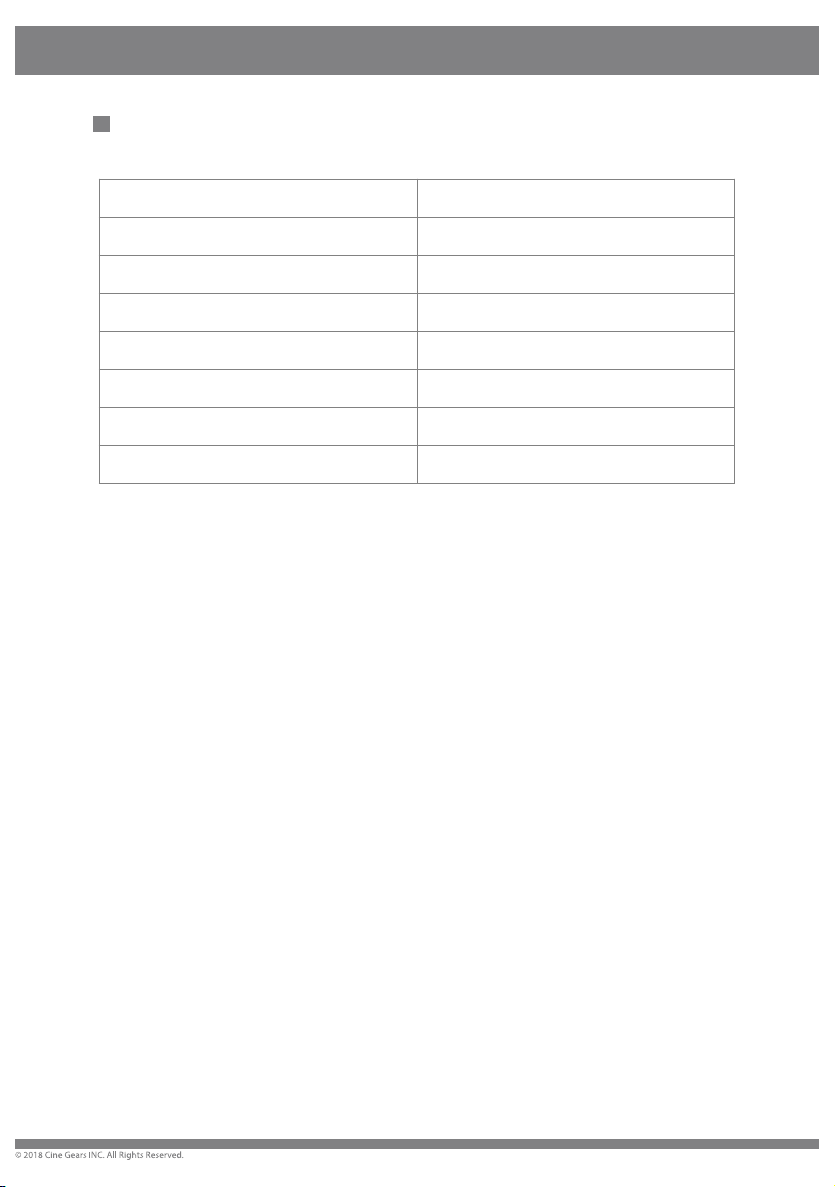
Supports full PSF resolutions
25PFS in = 25PFS out 23.98P in = 23.98P out
29.97PSF in = 29.97PSF out 24P in = 24P out
30PSF in = 30PSF out 25P in = 25P out
50i in = 50i out
59.94i in = 59.94i out
60i in = 60i out
29.97P in = 29.97P out
30P in = 30P out
13
Page 17
Other transmitter is working on the same or
adjacent channel.
Connect the transmitter to video source by SDI/HDMI
cable.
TV.
Unplug and then plug the HDMI cable of the TX and
player.
Trouble Shooting
Trouble Shooting
TROUBLES&POSSIBLE REASONS: SOLUTON:
Displaying “Waiting for connection…” for a long time
Transmitter is not powered up. Power on the transmitter.
Transmitter or receiver is not placed correctly. Place the TX or RX correctly.
The transmitter and receiver are too far away. Move the receiver closer to the transmitter.
Several solid wall partition on TX and RX. Reduce the number of solid walls between TX and RX.
There are so many obstacles between TX and RX. Move the receiver closer to the transmitter.
No Video Signal received
Transmitter and video source are not connected.
OSD Information on TV
The video source is turned OFF Power ON the video source.
Bad contact of cable of transmitter. Remove and then re-plug the transmitter
Abnormal working of transmitter Reboot the transmitter
Problem with cable between TX and video source Change the SDI/HDMI cable
Player NOT support the output resolution format. Switch the output video resolution to other modes.
The TV/Monitor NOT support HDCP authentication Replaced with HDCP-certified TV/Monitor.
No signal input to Receiver or TV/Monitor
Receiver is turned OFF Power on receiver.
Receiver and TV are not connected. Connect receiver and TV/Monitor via SDI/HDMI input.
TV/Monitor NOT switched to SDI/HDMI input. Switch TV/Monitor to SDI/HDMI input.
Bad contact of the cable of receiver or TV/Monitor. Remove then re-plug the SDI/HDMI cable.
TV/Monitor turn into standby mode. Switch the TV/Monitor to normal operation mode.
Abnormal working of receiver. Reboot the receiver.
No image appear on TV/Monitor
Image
Bad contact of receiver or cable. Re-plug the cable of the receiver or TV/Monitor.
Abnormal working of receiver. Reboot the receiver.
Receiver failure. Please contact your retailer.
Abnormal color on TV screen
Bad contact of cable of receiver or TV/Monitor.
Bad contact of cable of transmitter or video source.
Abnormal working of transmitter or receiver. Reboot the transmitter and receiver.
Turn off other transmitter, or change channel.
Unplug and then plug the HDMI cable of the receiver or
141516
Page 18
Page 19
Page 20
17
 Loading...