

Page 1

User Manual for
GHOST Bikes
Page 2

GHOST
User Manual Status 04/2009 // Spec 2010
1.2
1 About this User Manual ............................................................................1.6
1.1 User manual.......................................................................................1.6
1.1.1 Scope.................................................................................................1.6
1.1.2 Referenced documents......................................................................1.7
1.2 Conventions ....................................................................................... 1.7
1.2.1 Symbols..............................................................................................1.7
1.2.2 Definitions of positions ....................................................................... 1.8
1.2.3 List of abbreviations ........................................................................... 1.8
1.2.4 Definitions of terms.............................................................................1.8
2 For Your Safety........................................................................................ 2.10
2.1 Use your bike for its intended purpose.............................................2.10
2.1.1 Who is allowed to ride your bike?.....................................................2.10
2.1.2 How are you allowed to ride your bike? ...........................................2.10
2.1.3 Where are you allowed to ride your bike?........................................ 2.11
2.1.4 In what condition must your bike be for riding?................................ 2.12
2.1.5 What must you not do ...................................................................... 2.13
2.2 Residual risks................................................................................... 2.14
2.2.1 Hazards due to incorrect final assembly ..........................................2.14
2.2.2 Hazards due to improper use........................................................... 2.14
2.3 Disposal............................................................................................2.15
3 Scope of Supply, Technical Data...........................................................3.16
3.1 Scope of supply................................................................................ 3.16
3.2 Technical data.................................................................................. 3.16
4 Design and Function...............................................................................4.17
4.1 Categories........................................................................................ 4.17
4.2 Mountain bike (AMR, AMR Plus, AMR Square, ASX, ERT, FR
Northshore, 4X, DIRT, RT, HTX, MISS, MISS AMR, MISS RT, SE) 4.17
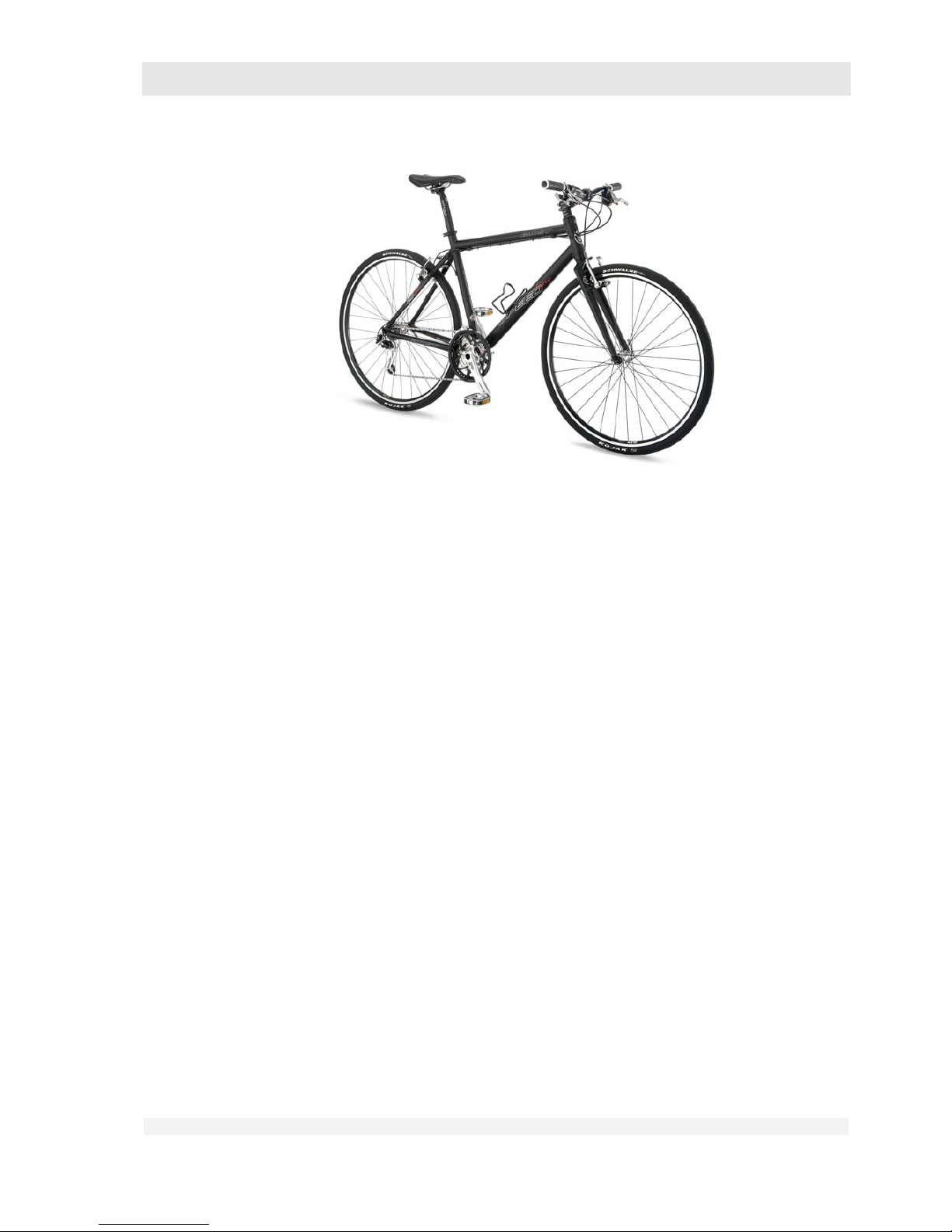
4.3 Cross bike (CROSS Series)............................................................. 4.21
4.4 Street (RACE, SPEEDLINE Series).................................................4.21
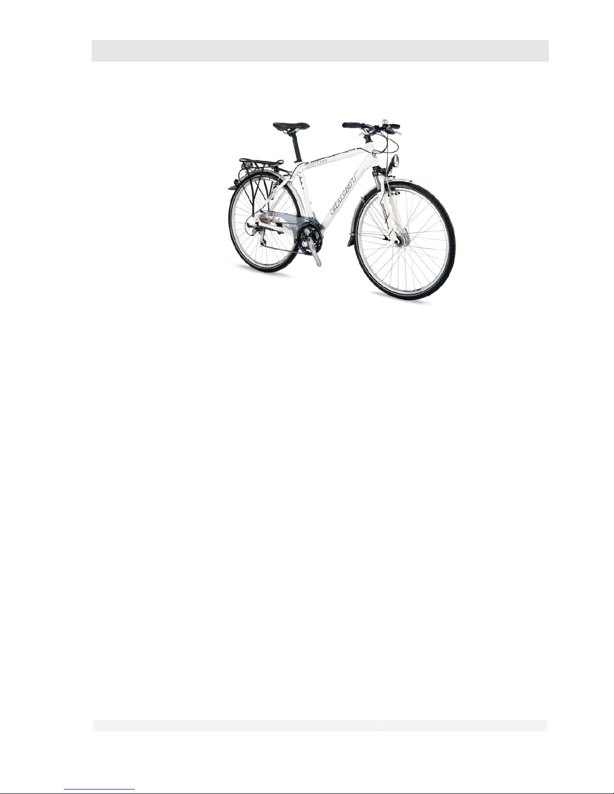
4.5 Trekking bike (TR Series).................................................................4.23
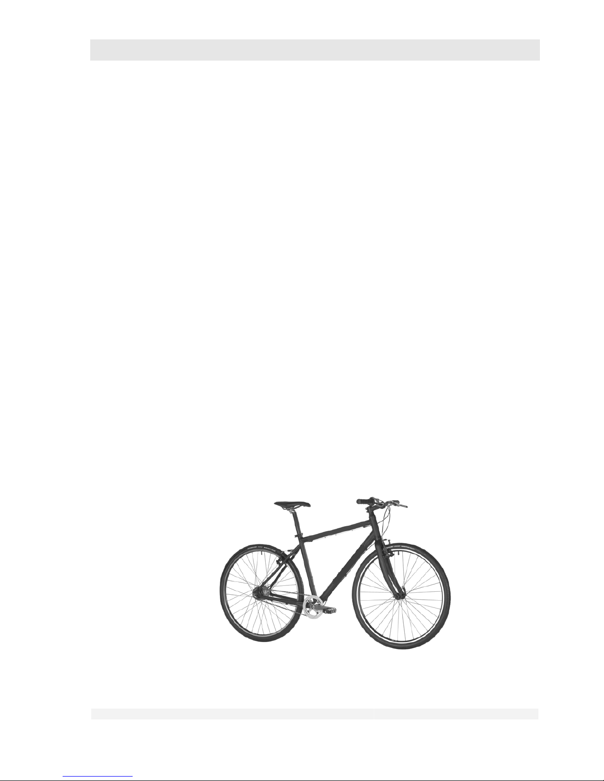
4.6 Children’s bikes (POWERKID Series)..............................................4.24
4.7 General information..........................................................................4.25
4.7.1 Gears................................................................................................4.25
4.7.2 Frames and forks ............................................................................. 4.25
4.8 Notes on carbon materials ............................................................... 4.27
4.8.1 Information on the frame construction..............................................4.28
4.8.2 Proper handling of carbon parts....................................................... 4.28
5 Before Using for the First Time.............................................................. 5.30
6 Before Every Use..................................................................................... 6.31
6.1 Inspect the wheels............................................................................6.31
Page 3

GHOST
User Manual Status 04/2009 // Spec 2010
1.3
6.1.1 Check the installation.......................................................................6.32
6.1.2 Check the wheel rims....................................................................... 6.32
6.1.3 Check the tyres ................................................................................ 6.34
6.1.4 Check other points ........................................................................... 6.37
6.2 Inspect the saddle and saddle post.................................................. 6.38
6.3 Inspect the handlebars and handlebar stem....................................6.39
6.4 Inspect the handlebar attachments..................................................6.40
6.5 Inspect the headset.......................................................................... 6.41
6.6 Inspect the spring fork...................................................................... 6.43
6.7 Inspect the rear wheel suspension ................................................... 6.43
6.8 Inspect the brakes............................................................................ 6.43
6.8.1 Check the rim brake with cable (racing bike version).......................6.44
6.8.2 Check the rim brake with cable (MTB version)................................. 6.47
6.8.3 Check the hydraulic rim brakes........................................................ 6.49
6.8.4 Check the hydraulic disc brake ........................................................ 6.50
6.8.5 Check the back-pedal brake.............................................................6.52
6.9 Inspect the drive and chain .............................................................. 6.52
6.10 Inspect the lighting system............................................................... 6.53
6.11 Inspect the luggage rack..................................................................6.53
6.12 Inspect the mudguards.....................................................................6.53
6.13 Check other points ........................................................................... 6.54
7 Adjusting and Operating the Bike..........................................................7.56
7.1 Adjust the adjustable handlebar stem (option)................................. 7.56
7.2 Adjust the saddle position ................................................................ 7.56
7.3 Adjust the saddle height................................................................... 7.58
7.4 Adjust the spring fork........................................................................7.58
7.5 Adjust the rear wheel suspension .................................................... 7.59
7.6 Operating the gear shift .................................................................... 7.59
7.6.1 Shimano Rapidfire/ Shimano Rapidfire 2-Way Release/
Shimano EZ Fire ..............................................................................7.65
7.6.2 Sram MTB........................................................................................7.67
7.6.3 Twist grip switch............................................................................... 7.68
7.6.4 Shimano STI (on RACE Series only) ...............................................7.69
7.6.5 Sram Force / Rival / Red (on RACE Series only).............................7.70
7.7 Using the brakes .............................................................................. 7.71
7.8 Operating the quick-release hub axle...............................................7.72
7.9 Use of clipless pedals.......................................................................7.79
7.10 Loading the luggage rack................................................................. 7.84
8 Faults When Riding................................................................................. 8.86
8.1 Gear shift, drive................................................................................ 8.86
8.2 Brakes..............................................................................................8.87
8.3 Frame and suspension.....................................................................8.88
8.4 Mudguards, luggage rack, lights ...................................................... 8.89
Page 4

GHOST
User Manual Status 04/2009 // Spec 2010
1.4
8.5 Wheels and tyres..............................................................................8.89
9 After an Accident or Fall.........................................................................9.91
10 Transporting the Bike ...........................................................................10.92
10.1 Removing and installing wheels..................................................... 10.92
10.1.1 All categories except RACE Series................................................ 10.93
10.1.2 RACE Series................................................................................10.108
10.2 Install and remove saddle post with saddle..................................10.115
11 Cleaning and Maintaining the bike.....................................................11.123
12 Storing the Bike for Prolonged Periods ............................................12.127
13 Warranty, Guarantee...........................................................................13.128
General .....................................................................................................13.128
Stability guarantee on frames from model year 2008...................................13.128
14 Delivery Certificate..............................................................................14.129
15 Imprint.................................................................................................. 15.131
Page 5

GHOST
User Manual Status 04/2009 // Spec 2010
1.5
Dear Customer,
We wish to congratulate you on your choice of a bike from our company, and to thank you for the
faith placed in us.
With the purchase of this bike you have acquired a high-quality, environmentally friendly and
sporting means of travel with which you will have a great deal of pleasure while at the same time
doing something for your health and fitness.
Even after providing advice and carrying out the final assembly, your bike dealer is still very
important to you. He is your contact person for maintenance, inspections, modifications and repairs
of all kinds. Should you have any questions about our product, please contact your bike dealer.
Page 6
GHOST
User Manual Status 04/2009 // Spec 2010
1.6
1 About this User Manual
1.1 User manual
Danger of personal injury and material damage!
Failure to observe the information in this user manual can result in dangerous
riding situations, falls, accidents and material damage.
Read this user manual carefully before using your bike for the first time.
All the parts of the bike mentioned below are illustrated in the figures.
Keep this user manual in a safe place and pass it on together with the
bike if you should resell or give away the bike.
It is your responsibility to inspect your bike as prescribed and to have
any necessary work carried out.
If any part(s) of this user manual are not comprehensible, please consult
your dealer.
Danger of personal injury and material damage!
User manual for children and youths
.
This user manual is directed at the guardians
of the children and youths who
use this bike.
If the children and/or youths under your guardianship fail to observe the
information in this user manual this can result in dangerous riding situations,
falls, accidents and material damage.
Where in this user manual sentences such as “You can get ...”, “Have
your bike...” etc. occur, these are directed in each case at the child or
youth and his/her bike.
Go through this user manual together and explain all the points to your
child, in particular the safety precautions.
As guardian you are responsible for ensuring the safety of this bike and
its proper use.
1.1.1 Scope
This user manual applies exclusively to the bikes from GHOST Bikes GmbH with which this user
manual is supplied.
Page 7
GHOST
User Manual Status 04/2009 // Spec 2010
1.7
Danger of personal injury and material damage!
This user manual is not intended to teach you how to ride a bike.
This user manual is not intended to teach you riding techniques.
1.1.2 Referenced documents
• Component user manuals
Danger of personal injury and material damage!
Due to the wide variety of existing bike components, it is not possible to
produce a generally applicable user manual.
Therefore always observe also the information in the component user
manuals supplied with the bike.
This information takes priority in all cases over deviating information in
the following text.
1.2 Conventions
1.2.1 Symbols
Note!
Draws attention to information of particular importance.
Warning!
Draws attention to the possibility of minor personal injuries and possible
material damage.
Danger!
Draws attention to the possibility of serious personal injury or even death.
Page 8
GHOST
User Manual Status 04/2009 // Spec 2010
1.8
Risk of burns!
The temperature is above 45° C (solidification of egg white) and can cause
burns to the human skin.
1.2.2 Definitions of positions
When the positions “right”, “left”, “front” or “rear” are referred to in this user manual, these are
always as seen “in the direction of travel”.
1.2.3 List of abbreviations
StVO
German road traffic regulations
StVZO
German motor vehicle safety standards
MTB
Mountain bike
HWK
Chamber of Commerce
1.2.4 Definitions of terms
Dealer/approved
workshop
In Germany: The term “dealer” and/or “approved workshop” as used
in this user manual refers to dealers with qualifications as twowheeler mechanic and/or bike mechanic who are authorised by the
Chamber of Commerce to operate an approved workshop.
These must also be authorised by the manufacturer of this bike to
inspect and confirm the correct final assembly and safety for use of a
bike.
Correctly tightened
The term “correctly tightened” defines the condition in which the whole
surface of the screw/bolt head is firmly in contact with the component.
Not correctly
tightened
A loose screw or bolt can often be recognised by a protruding bolt
head.
Page 9
GHOST
User Manual Status 04/2009 // Spec 2010
1.9
Wobble
A deviation in concentricity at the wheel rim is referred to colloquially
as “wobble”.
Bar
Common unit of measure for air pressure
inch
abbreviated to ”
English or American unit of length often used for frame and wheel
sizes
1” = 2.54 cm
psi
pounds per square inch; English or American unit for pressure;
1 psi = 0.069 bar
Nm
Newton-metre; unit of measure for (tightening) torque
Hand force
The force that an average person can apply with moderate effort
using one hand.
Page 10
GHOST
User Manual Status 04/2009 // Spec 2010
2.10
2 For Your Safety
2.1 Use your bike for its intended purpose
2.1.1 Who is allowed to ride your bike?
Danger of personal injury and material damage!
The rider must be able to ride a bike, i.e. he/she must have the necessary basic
knowledge about the use of a bike and the necessary feeling of balance to be
able to steer and control a bike.
The rider must be of the right height for this bike (ask your dealer).
The rider must be physically and mentally capable of using this bike on
public roads, as long as the bike is approved for such use.
Children and youths must be able to operate the bike safely. The
operating elements (e.g. brake levers) must be suitable for children’s
hands.
2.1.2 How are you allowed to ride your bike?
Danger of personal injury and material damage!
Sit on the saddle or ride standing up on the pedals.
Hold the left-hand grip of the handlebars with your left hand and the
right-hand grip with your right hand.
When riding, place your left foot on the left pedal and your right foot on
the right pedal.
Use the bike exclusively as a pure means of travel.
Page 11
GHOST
User Manual Status 04/2009 // Spec 2010
2.11
2.1.3 Where are you allowed to ride your bike?
Danger of personal injury and material damage!
All bikes from this manufacturer are divided into categories. You can find the
category of your bike in your BIKE SERVICE CARD. It is entered there by your
dealer on purchase (see also chapter 4).
The following categories apply to streets and paths:
– Street: Asphalted surface
– Path: Sand, gravel or similar surface (e.g. timber access road, field
track)
– Solidified footpath: No or few roots, steps, stones or shoulders, etc.
– Non-solidified footpath: Frequent roots, steps, stones or shoulders,
etc.
– Bike park: Specially marked area for Freeriding, Downhill, 4X and
Dirt
Freeriding: Artistic and sporting use, rapid downhill riding in free
terrain.
Downhill: Downhill riding of specially marked tracks at high to very
high speed
4-X and dirt: Tracks similar to those for BMX
Your safety on these streets and paths depends on your speed.
The higher your speed, the greater your risk!
Note that all streets and paths may be damaged and/or have obstacles
that can impair your safety and damage your bike.
In such areas ride particularly slowly and carefully. If necessary push or
carry your bike over such obstacles.
Danger of personal injury and material damage!
From a technical point of view we have approved the following model series for
use up to
the following streets and paths.
• RACE: Street, no jumps
• Wheels of all categories if fitted with racing bike-type tyres (see below)
Street, no jumps
• SPEEDLINE: Street, paths in exceptional cases with fine and solid
subsoil, no jumps
• CROSS: Paths, no jumps
• TR: Paths, no jumps
• POWERKID 12” and 16”: Paths, no jumps
• POWERKID 20” and 24”: Solidified footpaths, no jumps
• SE, HTX, MISS, RT: Solidified footpaths, no jumps
• AMR, ASX: Non-solidified footpaths
Page 12
GHOST
User Manual Status 04/2009 // Spec 2010
2.12
• AMR Plus, AMR Square, ERT: Non-solidified footpaths in sporting
applications
• 4X, DIRT: Bike park, but without freeriding and downhill
• FR Northshore: Bike park
Sporting application: High speed so that e.g. when riding over edges, steps and
ground waves you jump with your bike.
Bikes of other categories can also be fitted with racing bike or racing bike-type
tyres. Such tyres can be recognised from the maximum width of 28 mm
indicated e.g. by two number of the tyre such as 28-622 or 28-559.
Such bikes may then only be used on asphalted streets.
Please consult your dealer.
Danger of personal injury and material damage!
Whenever using your bike, particularly for
Sporting applications (high-speed riding over edges, street steps,
ground waves, etc.)
Use of your bike in the bike park, for sporting applications, where there
is always a risk of accidents,
Adapt the use of your bike to your riding skills!
2.1.4 In what condition must your bike be for riding?
Your new bike is sports equipment and may only be used on public roads and paths when fitted
with the accessories stipulated in your local motor vehicle safety standards. In order to comply with
the latest motor vehicle safety standards your bike must exhibit i.a. the features described below in
excerpts.
For the full wording of the regulations in Germany, please refer to the StVZO
or consult your dealer.
For use outside Germany, please observe the traffic regulations applicable in
your country. Consult your dealer or the responsible authorities.
• Two independently functioning brakes
• A bell
• Dynamo-powered lights for front (white light) and rear (red light)
Page 13
GHOST
User Manual Status 04/2009 // Spec 2010
2.13
Racing bikes under 11 kg are exempted from the dynamo obligation.
Even racing bikes exempted from the dynamo obligation have to carry battery-
powered lighting during the day.
For the duration of the participation in races, racing bikes are exempted from
this obligation.
• White reflector at the front (often integrated into the front light) and a large red reflector marked
with the letter “Z” at the rear.
• Two yellow reflectors each for front and rear wheel; alternatively: Tyres with reflective stripes on
both sides
• Two yellow reflectors each for right and left pedal
All lighting components and reflector parts must be approved.
The approval is recognisable from the marking with a “K”, a wavy line and a
multi-digit number.
For correct attachment of these parts to your bike, please consult your dealer.
• Chain sprocket guard
2.1.5 What must you not do
Danger of personal injury and material damage!
Many cyclists like to modify their bikes and adapt them to their personal wishes.
Saddle, handlebars, pedals, brakes, tyres, suspension elements – there are
innumerable possibilities for subsequent modification of your bike.
Work on your bike – even seemingly simple operations – requires thorough
training, extensive know-how and great experience.
Unqualified work on your bike can result in dangerous riding situations, falls,
accidents and material damage.
Do not attach any parts to your bike that are not expressly approved for
your bike model.
Exceptions here are bike computers and bottle holders if they have been
selected and fitted by your dealer.
Please consult your dealer.
Have all attachment, modification, service and other work carried out
exclusively by your local approv ed workshop.
Page 14
GHOST
User Manual Status 04/2009 // Spec 2010
2.14
Danger of personal injury and material damage!
Roller training with carbon frame and/or carbon forks:
If your bike is fixed to a training device for roller training, the carbon fabric of
the clamped part may be damaged and break later. This can lead to dangerous
riding situations, falls, accidents and material damage.
Bikes with carbon forks must not be fixed to training devices where the
forks are clamped.
Bikes with carbon frames or frames with saddle and/or seat struts of
carbon must not be fixed to training devices where the rear wheel is
clamped.
2.2 Residual risks
2.2.1 Hazards due to incorrect final assembly
Danger of personal injury and material damage!
Incorrect final assembly of this bike can lead to dangerous riding situations,
falls, accidents and material damage.
Have the correct final assembly and the adjustment of the correct
seating position for you confirmed by your dealer.
Please use the preprinted form in this user manual.
2.2.2 Hazards due to improper use
Danger of personal injury and material damage!
Failure to observe the information in this user manual can result in dangerous
riding situations, falls, accidents and material damage.
Always wear a helmet when riding your bike.
Ride with foresight and defensively.
Do not ride after consuming alcohol.
Ride in such a way that you have your bike under control at all times
and can react correctly in the event of a sudden danger situation.
Be aware that the efficiency of the brakes and dynamo can decrease in
wet weather.
When riding, wear only suitable clothing that does not hinder the
operation of the bike or your sight.
Page 15

GHOST
User Manual Status 04/2009 // Spec 2010
2.15
Always wear tight-fitting legwear when riding. Loose clothing can
become tangled in the bike and lead to serious falls.
In the dark and with poor visibility, wear clothing with reflective stripes
and switch on your lights.
Transport your luggage only on suitable carrier systems. These are bike
backpacks or luggage carriers approved by the bike manufacturer.
Please consult your dealer if you have any questions.
Increased loads extend your braking distance.
Note that some items of clothing and/or the use of a backpack can
hinder your mobility.
Do not exceed the admissible total weight of your bike, see chapter 3.2.
Determine the admissible total weight by picking up your bike with the
complete load and standing in your complete riding gear together with
your bike on calibrated scales.
Observe the maintenance and care instructions in chapters 11 and 12.
2.3 Disposal
Dispose of your bike in an appropriate manner at the end of its service life.
Consult your dealer or an approved recycling company.
Page 16
GHOST
User Manual Status 04/2009 // Spec 2010
3.16
3 Scope of Supply, Technical Data
3.1 Scope of supply
GHOST bike with user manual
3.2 Technical data
Admissible ambient
temperatures
-10 to +50° C
Admissible total weight Trekking: 140 kg
MTB: 120 kg
4X / Dirt: 120 kg
Cross / Speedline: 120 kg
Race: 120 kg
Powerkid 24” (*): 100 kg
Powerkid 20” (*): 80 kg
Powerkid 12” / 16” (*): 50 kg
(*): 12” / 16”, 20” or 24” indicates the wheel size. This is indicated on the tyre. Please consult your
dealer.
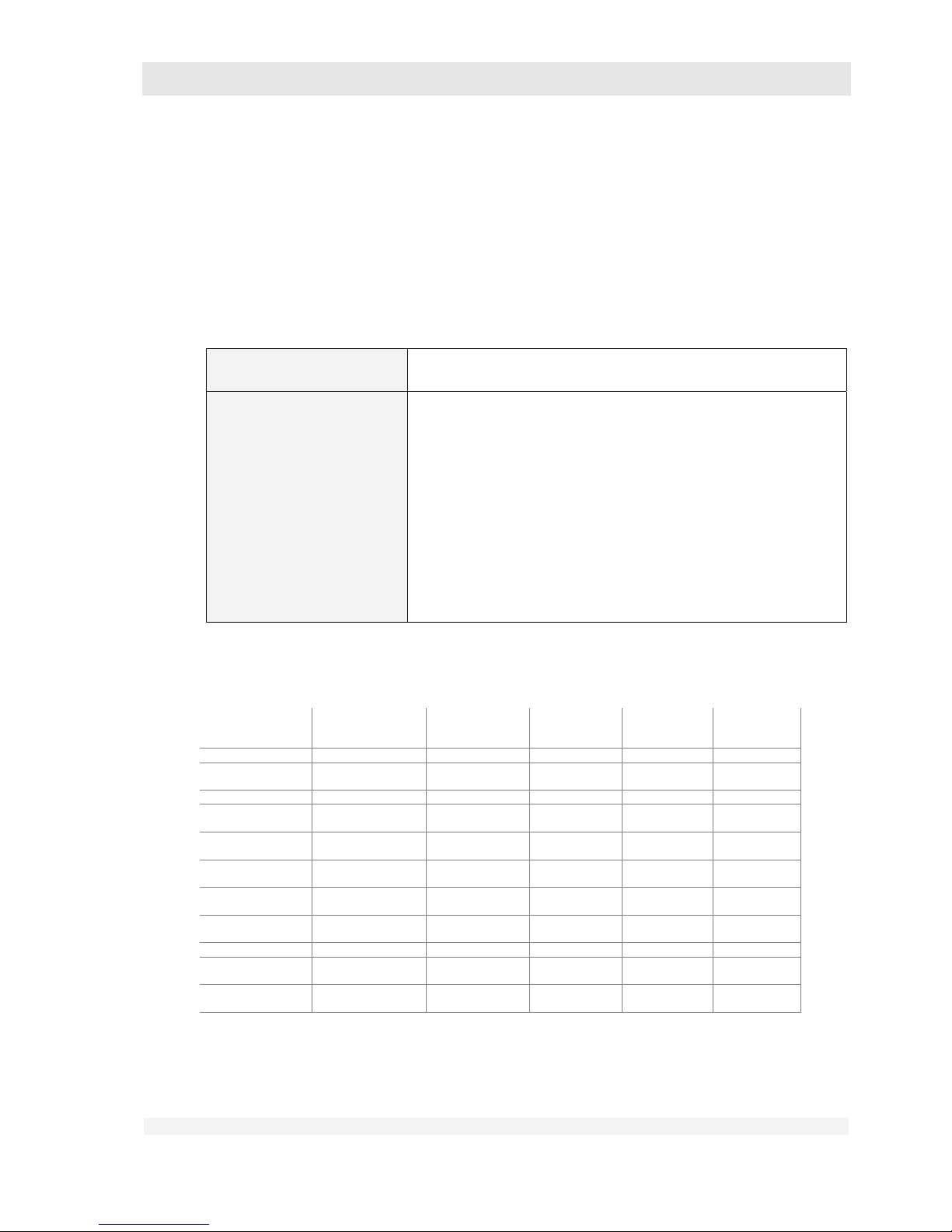
Component Manufacturer Model/Type Connection Type of
connection
Tightening
torque
(Nm)
Saddle post GID fixed
Saddle
clamp
One bolt 17-20
Saddle post
GHOST BMX
CroMo fixed
Saddle
clamp Two bolts 5-6
Saddle post Ritchey fixed
Saddle
clamp Two bolts 14-16
Saddle post Syncros fixed
Saddle
clamp Two bolts 14-16
Saddle post GID fixed
Saddle
clamp Two bolts 14-16
Saddle post GID
spring
suspension
Saddle
clamp Two bolts 5-6
Saddle post
clamp to frame
All
aluminium
frame
Saddle post
clamp
One bolt 5-6
Saddle post
clamp to frame
All carbon frame
Saddle post
clamp
One bolt 5-6
Table of tightening torques
Page 17
GHOST
User Manual Status 04/2009 // Spec 2010
4.17
4 Design and Function
4.1 Categories
We divide our bikes into the following categories. There are various series within these categories.
The category and series to which your bike belongs can be found in your BIKE SERVICE CARD at
the end of this user manual.
• Mountain bike (AMR, AMR Plus, AMR Square, ASX, ERT, FR Northshore, 4X, DIRT, RT, HTX,
MISS, MISS AMR, MISS RT, SE)
• Cross bike (CROSS)
• Street (RACE, SPEEDLINE)
• Trekking bike (TR)
• Children’s bikes (POWERKID)
You can find the category of your bike in the BIKE SERVICE CARD at the end of this user manual.
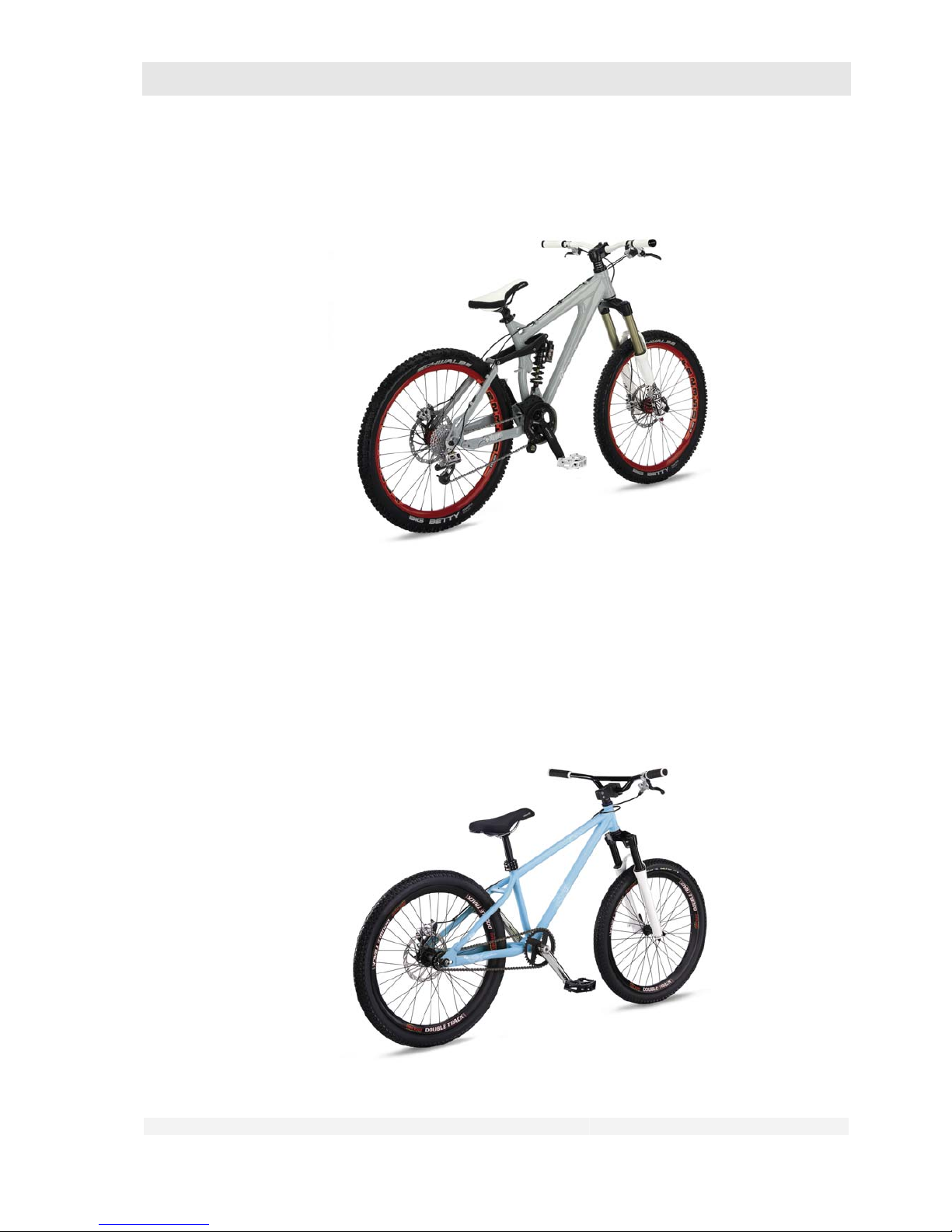
4.2 Mountain bike (AMR, AMR Plus, AMR Square, ASX, ERT, FR Northshore, 4X, DIRT,
RT, HTX, MISS, MISS AMR, MISS RT, SE)
No equipment in accordance with StVZO, equipped with dérailleur, rim brakes or disc brakes,
wheels with rim diameter 559mm / 26”.
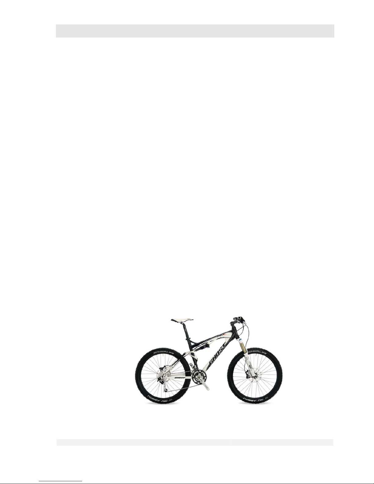
• AMR, ASX, Miss AMR Series:
– Fullies (see chapter 4.7.2) with 120 mm spring travel front and rear. Equally easy to ride up
and down hill.
Page 18
GHOST
User Manual Status 04/2009 // Spec 2010
4.18
• AMR Plus, AMR Square Series:
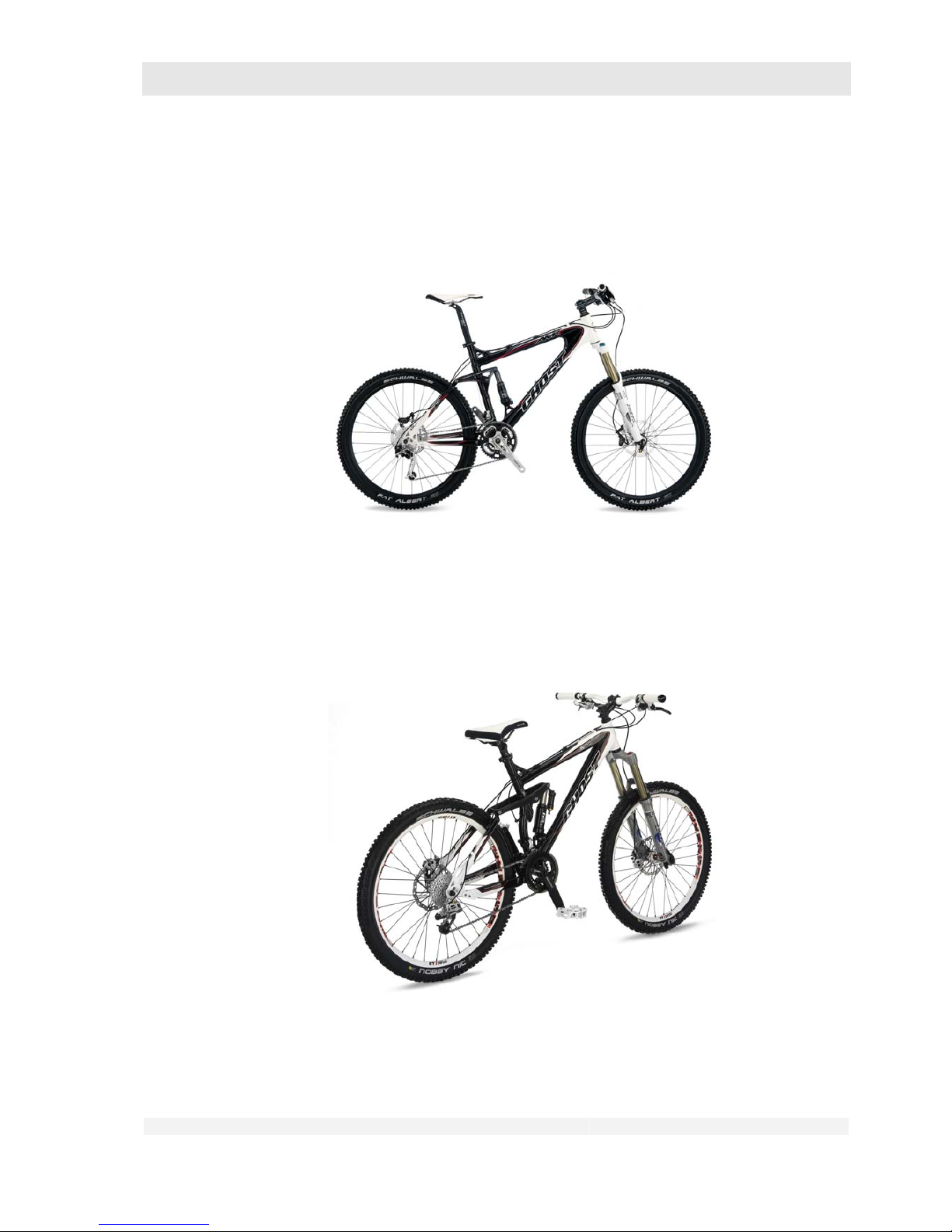
– Fullies (see chapter 4.7.2) with 100 – 140 mm spring travel front and 140 mm spring travel
rear. Easy to ride up and down hill. Greater importance is attached, however, to the
downhill properties.
• ERT Series:
– Fullies (see chapter 4.7.2) with 100 – 160 mm spring travel front and 160 mm spring travel
rear. The main focus here is on the downhill properties, but is also suitable for uphill riding.
CAUTION: Corresponding skill and experience are preconditions for the use of this sports
bike!
• FR Northshore Series:
– Fullies (see chapter 4.7.2) with 180 mm spring travel front and rear. The main focus here is
on the suitability for downhill and bike park.
Page 19
GHOST
User Manual Status 04/2009 // Spec 2010
4.19
CAUTION: Corresponding skill and experience are preconditions for the use of this sports
bike!
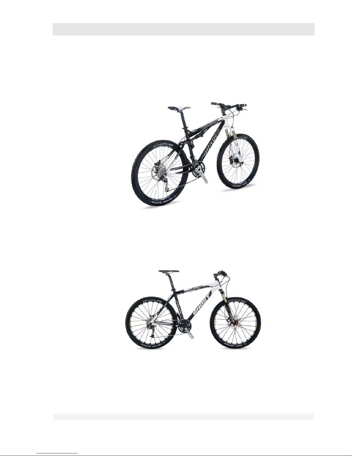
• 4X / DIRT Series:
– Hardtails (see chapter 4.7.2) with 100 mm spring travel front. The main focus here is on the
suitability for the bike park and for jumping.
– Equipment as for mountain bike, but some models with only one brake, without gears or
with gears only for the rear sprocket cassette.
CAUTION: Corresponding skill and experience are preconditions for the use of this sports
bike!
Page 20
GHOST
User Manual Status 04/2009 // Spec 2010
4.20
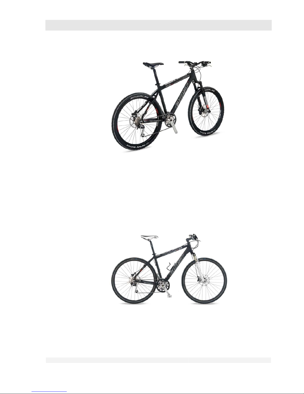
• RT, MISS RT Series:
– Fullies (see chapter 4.7.2) with 100 mm spring travel front and rear. Bikes with weight-
oriented configuration for the sporting rider.
• HTX / MISS Series:
– Hardtails (see chapter 4.7.2) with 100 mm spring travel front. Bikes with weight-oriented
configuration for the sporting rider.
• SE Series:
– Hardtails (see chapter 4.7.2) with 80 - 100 mm spring travel front. Sturdy universal bikes for
the tour-oriented leisure cyclist.
Page 21
GHOST
User Manual Status 04/2009 // Spec 2010
4.21
4.3 Cross bike (CROSS Series)
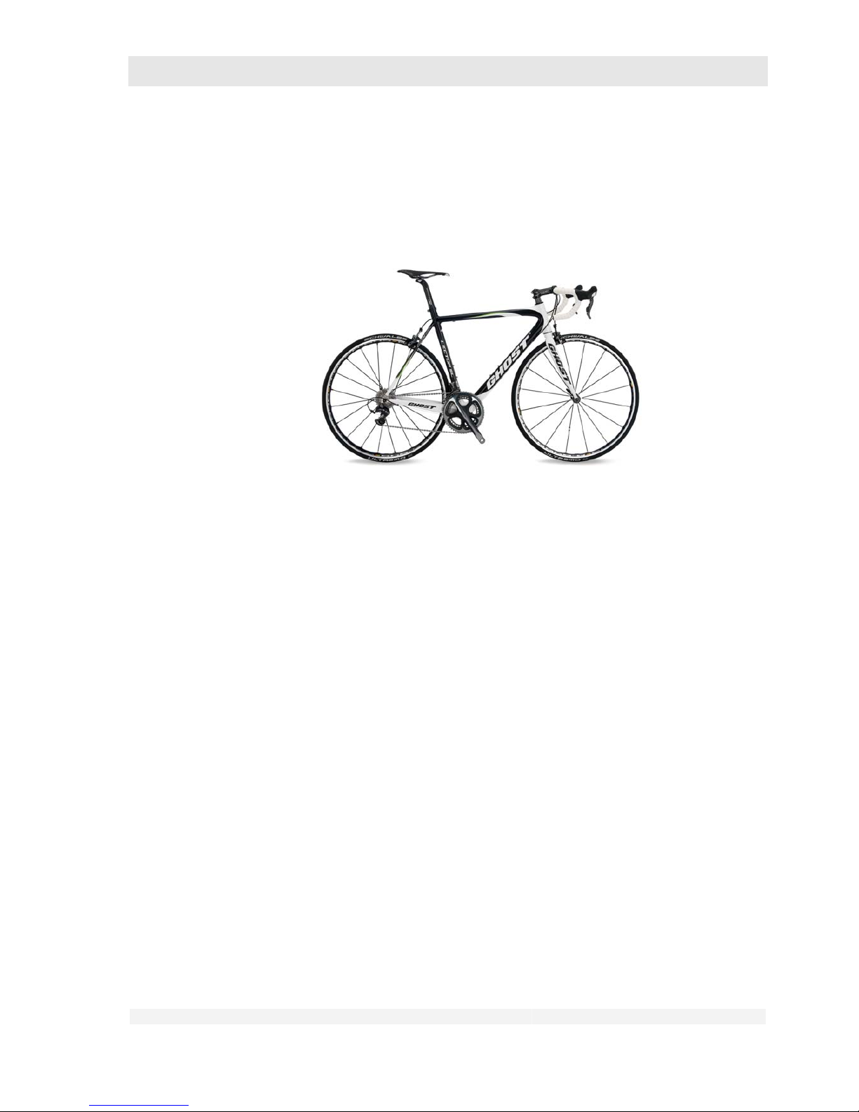
Equipment as for mountain bike, but wheels with larger rim diameter of 622 mm / 28”.
• CROSS Series:
– Hardtails (see chapter 4.7.2) with 60 mm spring travel front. Universal bikes for speedy
progress on streets and paths.
4.4 Street (RACE, SPEEDLINE Series)
No equipment in accordance with StVZO, equipped with dérailleur, rim brakes, wheels with rim
diameter 662 mm / 28”.
Page 22
GHOST
User Manual Status 04/2009 // Spec 2010
4.22
• RACE Series:
– Racing bikes without frame suspension, rigid forks and racing handlebars for rapid sporting
progress on the street.
– Racing bike brakes (see chapter 6.8.1)
• SPEEDLINE Series:
– Bikes without frame suspension and rigid forks for rapid, comfortable progress on the road.
– Straight or mountain bike-type handlebars
– Gear shift lever as for mountain bikes
– Rim brakes as for mountain bikes
– Slightly wider tyres than for the RACE Series
Page 23
GHOST
User Manual Status 04/2009 // Spec 2010
4.23
4.5 Trekking bike (TR Series)
Equipment in accordance with StVZO, equipped with dérailleur, two rim or disc brakes, luggage
rack, mudguards
• TR Series:
– Hardtails (see chapter 4.7.2) with 60 mm spring travel front.
– Universal, fully equipped bikes for comfortable progress on streets and paths.
– Straight or mountain bike-type handlebars
– Gear shift lever as for mountain bikes
– Rim or disc brakes as for mountain bikes
– Hub dynamo
Page 24
GHOST
User Manual Status 04/2009 // Spec 2010
4.24
4.6 Children’s bikes (POWERKID Series)
No equipment in accordance with StVZO, equipped with derailleur or no gears, rim and/or backpedal brakes.
• POWERKID 12” and 16”:
– Frame without suspension and rigid forks
– No gears
– Rim brakes front
– Back-pedal brake rear
– Stabilisers
– Wheel size 12” or 16”
• POWERKID 20”:
– Very similar to a MTB
– Hardtail (see chapter 4.7.2) with spring fork with up to 50 mm spring travel
– Derailleur rear with 7 speeds
– Rim brakes as for mountain bikes
– Wheel size 20”
• POWERKID 24”:
– Corresponds to a MTB but with smaller wheel size
– Hardtail (see chapter 4.7.2) with spring fork with up to 50 mm spring travel
– Derailleur gear with 24 speeds
Page 25
GHOST
User Manual Status 04/2009 // Spec 2010
4.25
– Rim brakes as for mountain bikes
– Wheel size 24”
4.7 General information
4.7.1 Gears
On bikes with several gears a distinction is made between
• Derailleur gear, recognisable from the sprocket assembly on the rear wheel hub and a pedal
assembly with several chainwheels, or
• Hub gear, recognisable from a “fat” rear wheel hub.
These gear assemblies provide you with the optimum gear for every speed and simplify, for
example, the climbing of hills.
The number of gears is determined as follows:
• Derailleur gear: Number of chainwheels at the front multiplied by the number of sprockets at
the rear, e.g.: 3 chainwheels x 9 sprockets = 27 gears.
• Hub gear: The number of gears corresponds to the highest number on the gear shift indicator.
4.7.2 Frames and forks
Bike frames are available in the following forms:
• Without suspension:
With rigid fork and rigid frame
– Model series RACE, SPEEDLINE, POWERKID 12” and 16”
• With half suspension (“hardtail”): With fork suspension and rigid frame
Page 26
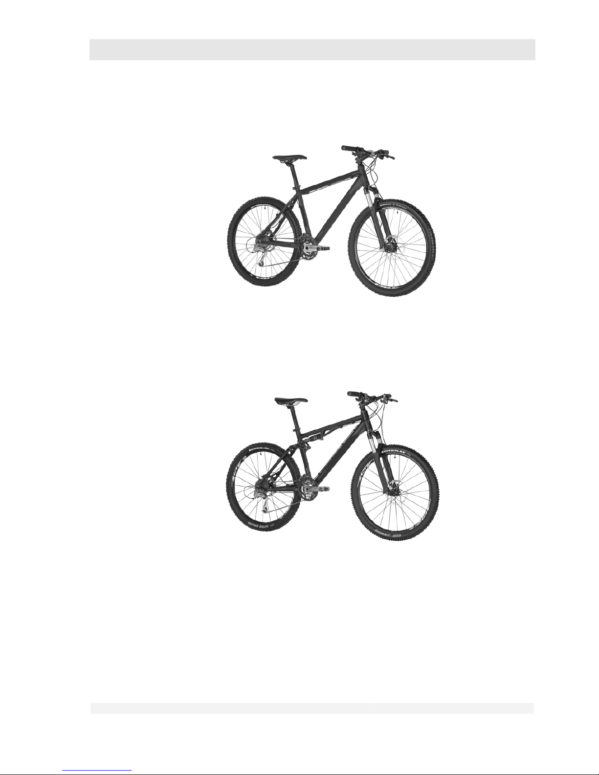
GHOST
User Manual Status 04/2009 // Spec 2010
4.26
– Model series 4X, DIRT, MISS (except MISS AMR, MISS RT), HTX, SE, CROSS, TR,
POWERKID 20” and 24”
• Full suspension:
With fork suspension and rear wheel suspension
– Model series AMR, AMR Plus, AMR Square, ASX, ERT, FR Northshore, RT, MISS RT,
MISS AMR
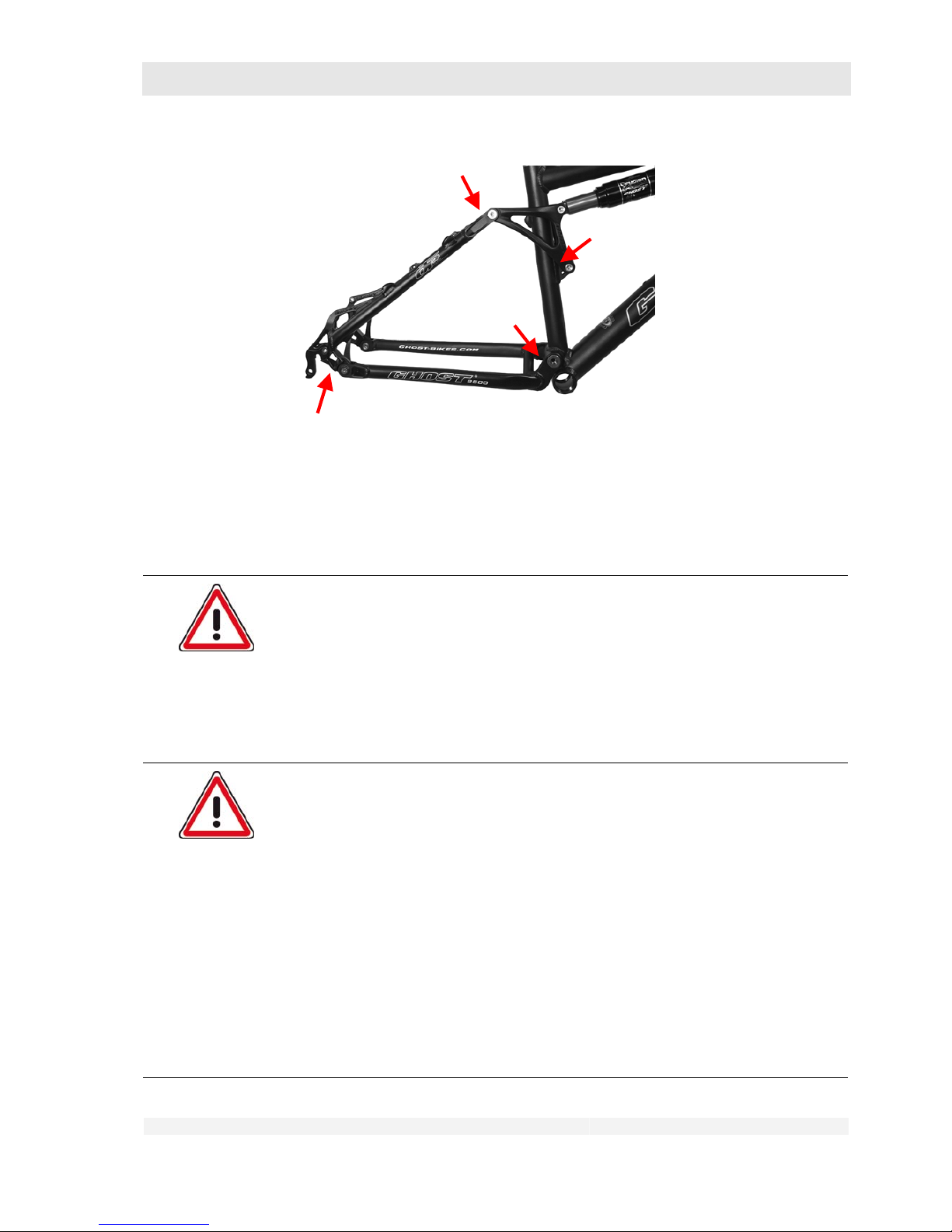
For full suspension bikes there are various suspension systems with different numbers of pivot
joints.
Page 27
GHOST
User Manual Status 04/2009 // Spec 2010
4.27
Four-pivot frame
The number of pivots can be easily counted. The connection to the spring element does not count
as a pivot.
4.8 Notes on carbon materials
Danger of personal injury and material damage!
Carbon is a modern material in bike and motor vehicle construction. Carbon
parts are, however, delicate and sensitive. Mistakes during assembly or use can
result in fractures and hence in dangerous riding situations, falls, accidents and
material damage.
Be sure to observe all the instructions on the use of carbon parts.
If you have any questions about the use of carbon parts, please consult
your dealer.
Danger of personal injury and material damage!
Impact loads that can occur if using the bike for other than the approved
purpose (see chapters 2.1.3 and 4) and collisions with flying stones can lead to
invisible damage in the carbon fabric and/or to delaminations (= separation of
the bonded carbon layers).
Such prior damage together with the forces occurring during operation can
cause carbon parts to suddenly break and hence result in dangerous riding
situations, falls, accidents and material damage.
Use your bike only for its intended purpose (see chapters 2.1.3 and 4)
After accidents or other major mechanical loads not caused by normal
bike operation, carbon frames and parts may no longer be used.
After a fall or accident, immediately contact a dealer authorised by the
manufacturer and have the parts concerned sent in to the manufacturer
for inspection.
Page 28

GHOST
User Manual Status 04/2009 // Spec 2010
4.28
Carbon is a colloquial expression for carbon fibre-reinforced plastics. This designates a fibre-plastic
composite material in which the carbon fibres are embedded in several layers in a plastic matrix.
This matrix consists of thermosetting plastics (epoxy resin). The primary functions of the matrix
material are to transmit and distribute the occurring forces and to fix the fibres.
As with all fibre composite materials, the tensile strength is significantly higher than the strength
transverse to the fibre direction. The carbon fibres are therefore arranged in multiple directions in
order to be able to meet all the occurring forces.
4.8.1 Information on the frame construction
Exact analyses and realistic simulations of the forces occurring in the frame have enabled the fibre
orientations in the different areas, such as in the pedal bearings or at the control tube, to be
designed more efficiently.
Our GHOST carbon frames are manufactured using the Tube2Tube process. This technique of
which only a few manufacturers have a perfect command enables GHOST to employ the material
efficiently exactly where it is needed, and to leave it away where it is not needed. In this process,
individual prefabricated frame segments are joined together in turn until the frame has been
completely assembled.
These high-end products are produced manually. Differences can therefore occur in the finish, but
these are not grounds for complaint.
4.8.2 Proper handling of carbon parts
1. No additional parts may be attached to carbon tubes by means of clips, screws,
clamps or by any other methods that exert mechanical loads on the carbon
tube. The forces occurring can damage the carbon fabric.
2. Clamping on assembly stands:
• Never
clamp your bike at a carbon tube or carbon saddle post in the jaws of
an assembly stand.
• Use an aluminium saddle post with the same diameter and insert it into your
frame as described in chapter 7.3.
• You can then clamp your bike in the jaws of an assembly stand at this
saddle post.
3. Take care when using shackle locks! Under certain circumstances these can
damage your frame.
• Ensure when using shackle locks that these only touch the corresponding
carbon tube and do not exert any force on the tube.
4. Saddle clamping bracket / saddle post:
• The maximum tightening torque of the saddle clamping bracket bolt is 6 Nm
(minimum torque 5 Nm).
• The saddle tube must not be reamed out or otherwise mechanically
machined.
• Saddle post and saddle tube must not be greased. Use only the carbon
assembly paste supplied with the bike.
Page 29

GHOST
User Manual Status 04/2009 // Spec 2010
4.29
5. Bottle holders:
• The thread sets are provided for the attachment of commercially available
bottle holders. The maximum tightening torque of the screws for fastening
the bottle holder to the frame is 4 Nm.
6. Roller training:
• The use of roller trainers with rigid clamping is not
permitted. The rigid
clamping of the fork ends or quick-release axle exerts loads that differ
significantly from those occurring during the permitted use for riding. This
can result in damage to the bike frame.
• Use on a loose roller without rigid clamping of the frame is permitted.
CAUTION: This presupposes the necessary know-how!
7. Transport:
• Take particular care when transporting bikes with carbon frames. As with
our bikes with aluminium frames, they may only be transported inside motor
vehicles.
• Protect particularly the frame from contact with other parts. Use blankets or
similar protective covers.
• As with all our bikes, no rack systems or the like may be used that employ
clamping elements for fixing and attachment. The clamping forces may
cause damage to the tubes.
• Do not place other objects on the frame.
• Ensure that the bike cannot slip during transport.
Page 30
GHOST
User Manual Status 04/2009 // Spec 2010
5.30
5 Before Using for the First Time
Danger of personal injury and material damage!
A bike that is not completely ready for use can lead to dangerous riding
situations, falls, accidents and material damage. The same hazards apply if you
are not yet familiar with your new bike and its operation.
Familiarise yourself with your bike before riding for the first time.
In particular check which brake lever actuates the front brakes and
which the rear brakes, see chapter 7.8.
Modern brakes have a very strong braking effect. Excessively powerful
actuation of the brake lever can result in the respective wheel locking
and leading to a fall or accident.
Familiarise yourself gradually with the braking effect of your bike on
safe ground.
With new rim brakes and after replacement of the brake blocks, the full
braking effect sets in only after a certain period of operation. Therefore
anticipate longer braking distances for a certain time.
Disc brakes first have to be run in. The full braking effects develops only
after the running-in period. Observe the enclosed running-in
instructions from the brake manufacturer.
If your bike is equipped with optional clipless pedals that fix the shoe to
the pedal:
Practice getting on and off your bike before use.
Clipless pedals are not safety pedals; observe the instructions in
chapter 7.10.
Should you remove saddle post and front and/or rear wheel for transport
of your bike after purchase, observe the instructions in chapter 10.
1. Have the correct final assembly and the inspection of the readiness for use of
your bike confirmed by your dealer.
2. Have your dealer adjust the correct seating position for you.
You can carry out fine adjustments and minor modifications yourself as
described in chapters 7.2 and 7.3.
3. Use your bike only when your dealer has instructed you and familiarised you
with the technology of your bike.
4. Protect your bike with spray wax, see chapter 11.
5. Also observe chapter 6 before the first use.
Page 31
GHOST
User Manual Status 04/2009 // Spec 2010
6.31
6 Before Every Use
Danger of personal injury and material damage!
A bike that is not completely ready for use can lead to dangerous riding
situations, falls, accidents and material damage.
Also consider the possibility that your bike may have fallen ov er or been
manipulated by unknown persons while unsupervised.
Check that your bike is safe for use before every journey.
Memorise the correct condition of your bike when new so that you can
later more easily recognise any deviations from the correct condition
(taking photographs can be a valuable aid here).
Contact your dealer immediately if you discover that your bike is not in
the proper condition.
Ride your bike again only when it has been properly repaired by your
dealer.
The parts described below are not installed on all bikes. Some parts can also
be installed later.
Check in chapter 4 and with the aid of the following illustrations which
equipment your bike has. Carry out the corresponding checks.
If you are not sure about anything or have any questions, please contact your
dealer.
1. Carry out a visual inspection of the whole bike.
• Check all mounting screws / bolts for proper tightness (see chapter 1.2.4).
• Inspect the whole bike for dents, cracks, deep scratches or other
mechanical damage.
Contact your dealer if the visual inspection reveals faults of any kind.
6.1 Inspect the wheels
Inspect the front and rear wheels.
A wheel consists of:
• Hub
• Only on the rear wheel hub: Sprocket or sprocket assembly
Page 32
GHOST
User Manual Status 04/2009 // Spec 2010
6.32
• Brake disc, if installed
• Spokes / nipple
• Rim and
• Tyre, which in turn consists of
– Tyre,
– Inner tube and
– Rim tape
Some bikes are equipped with tubeless wheels. In this case tyres without inner tubes are fitted to
special rims. An inner tube can, however, also be installed.
On bikes with StVZO approval, rim reflectors may also be installed.
6.1.1 Check the installation
1. Shake both wheels strongly at right angles to the running direction.
• The wheels must not move in their mounting.
• The quick-release lever must be closed (see chapter 7.9).
• No cracking or grinding noises should be heard.
Contact your dealer if the inspection reveals faults of any kind.
6.1.2 Check the wheel rims
Danger of personal injury and material damage!
Worn rims and
/
or extreme wobble can lead to dangerous riding situations, falls,
accidents and material damage.
Worn rims must be replaced, wobble repaired!
Danger of personal injury and material damage!
With rim brakes: Soiled rims can impair the braking effect.
Soiled rims must be cleaned immediately (see chapter 11).
Page 33
GHOST
User Manual Status 04/2009 // Spec 2010
6.33
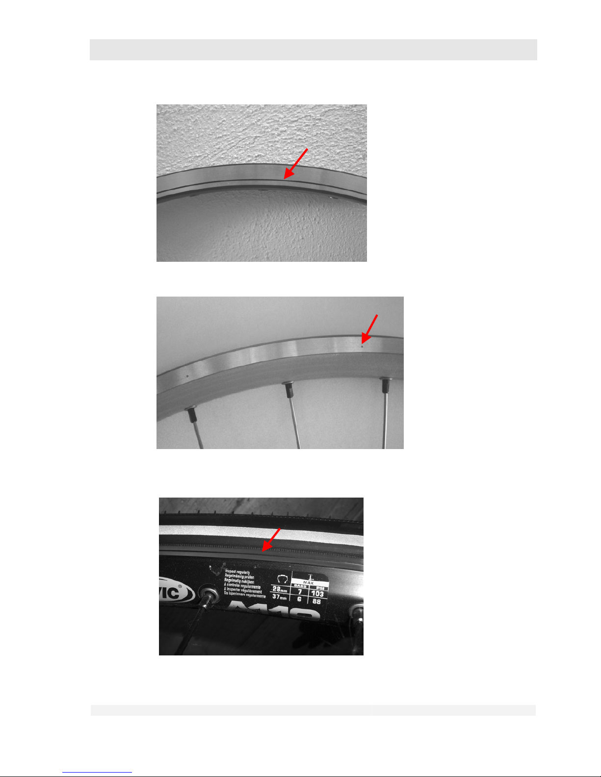
Wear indicator
Wear indicator
Wear indicator
1. Check the rims for wear:
Page 34
GHOST
User Manual Status 04/2009 // Spec 2010
6.34
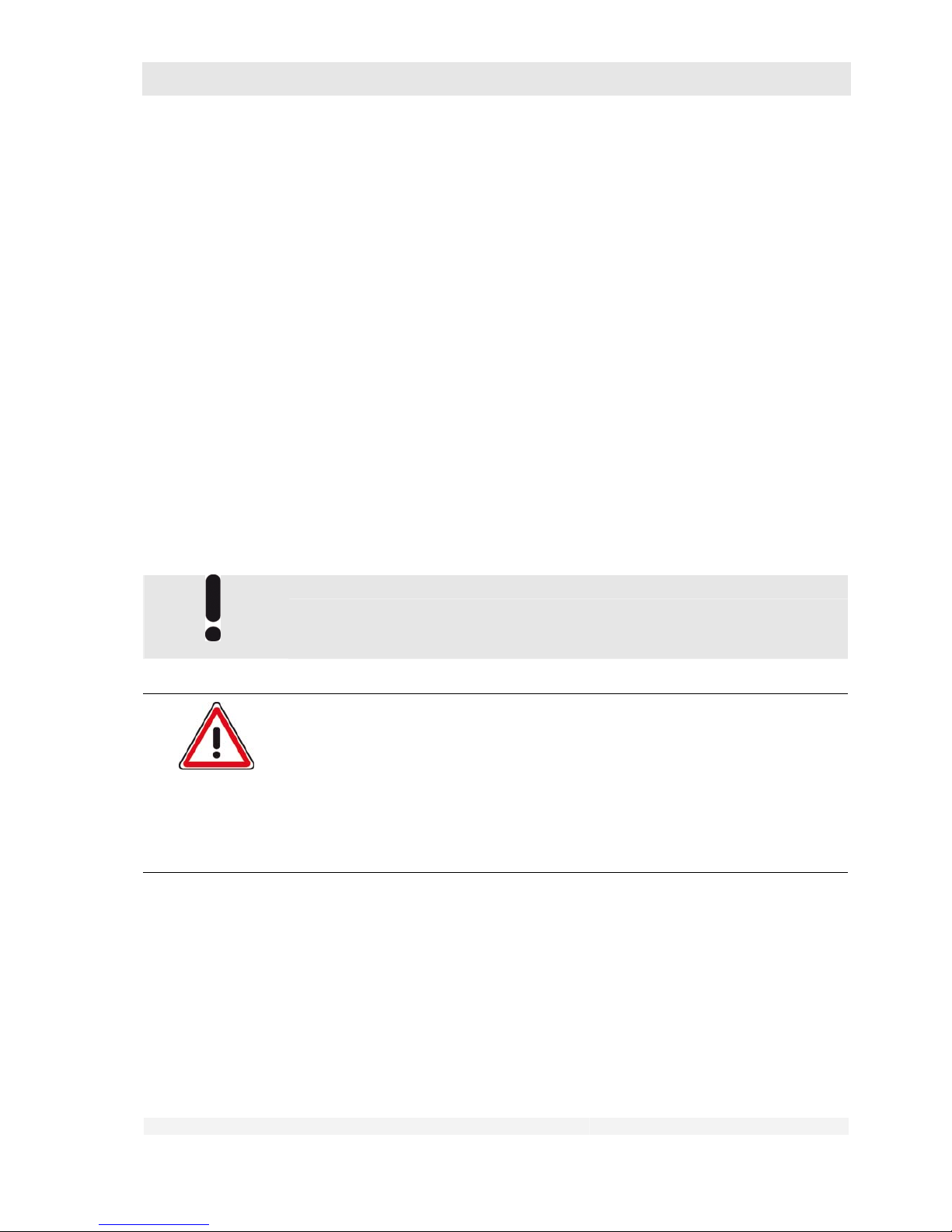
• Rims with wear indicators:
- Visual inspection
• Rims without wear indicators:
- Visual inspection
- Finger nail test: Run your finger nail across the rim flank. You should
not feel scratches or scores.
• If the wear indicator is no longer visible or the rims exhibit visible scratches
or scores that can be felt with your finger nail, the rim must be replaced.
2. Check the rims for wobble:
• Pick up the bike and rotate the front and rear wheel in turn.
• Pay attention to the clearance between rim and brake blocks, on bikes with
disc brakes to the distance between rim and frame strut or fork blade.
The maximum permissible deviation per revolution is 2 mm.
3. Inspect the rims for soiling, in particular for oil or grease.
Soiled rims must be cleaned immediately (see chapter 11).
6.1.3 Check the tyres
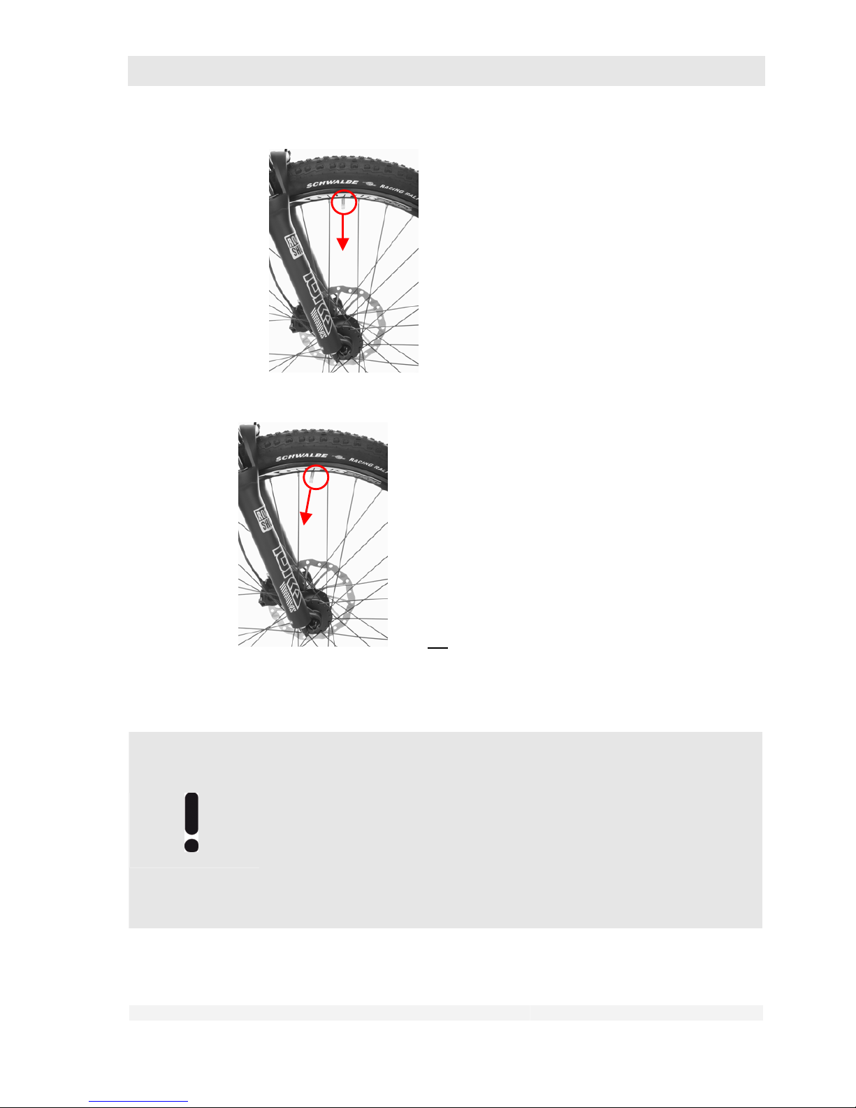
1. Check the valve position:
Does not apply to tubeless tyres.
Danger of personal injury and material damage!
If the valves are crooked, the valve foot may tear off while riding resulting in a
sudden loss of pressure in the tyre. This can lead to dangerous riding
situations, falls, accidents and material damage.
Have the positioning of the tyre on the rim corrected by your dealer.
You can carry out this work yourself if you are familiar with the removal
and installation of the wheels (see chapter 10.1) and the replacement of
tyres and tubes.
• If necessary, remove the valve nut.
• Check the valve position:
The valves must be pointing towards the middle of the wheel.
Page 35
GHOST
User Manual Status 04/2009 // Spec 2010
6.35
Valve pointing towards the middle of the wheel
Valve not pointing towards the middle of the wheel
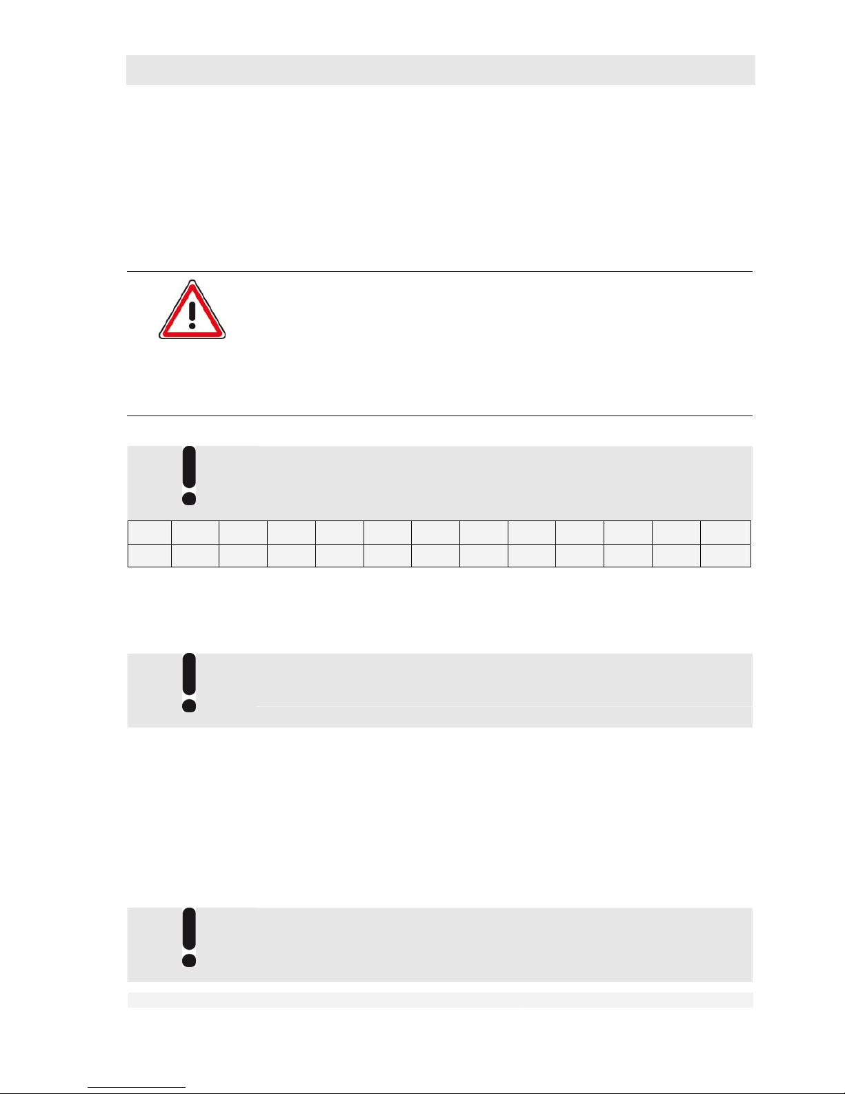
2. Check the tyre pressure:
Identify the type of tyres on your bike
Mountain bikes may be fitted with racing bike-type tyres,
racing bikes with trekking tyres.
Rule of thumb:
Mountain bike tyres: Tyre width more than 40 mm
Trekking / cross and fitness bike tyres: Tyre width from 28 mm – 40 mm
Racing bike-type tyres: Tyre width less than 28 mm
Contact your dealer if you are not sure which type of tyres is installed on your
bike.
Page 36
GHOST
User Manual Status 04/2009 // Spec 2010
6.36
Indicative values for the tyre pressure:
• For mountain bike tyres: 2.5 – 3.5 bar
• For trekking and city bike tyres: 3.5 – 5.0 bar
• For racing bike tyres: 6.0 – 10.0 bar
• For the right pressure for categories not listed here, please refer to the
pressure shown on the tyre or consult your dealer.
Danger of personal injury and material damage!
Insufficient tyre pressure can lead to an increase risk of accidents or tyre
damage, and in particular to dangerous handling behaviour. The tyre may come
off the rim in a curve; insufficient pressure also enhances the wandering of the
tyre on the rim. This can lead to dangerous riding situations, falls, accidents
and material damage.
Keep your tyres inflated to the prescribed pressure at all times.
Some tyre pressures are indicated in “psi”.
Convert the tyre pressure into bar using the following table.
psi 30 40 50 60 70 80 90 100 110 120 130 140
bar 2.1 2.8 3.5 4.1 4.8 5.5 6.2 6.9 7.6 8.3 9.0 9.7
Refer to the rim or tyre manufacturer’s specifications for the admissible tyre
pressure. The admissible tyre pressure is generally shown on the tyre flank.
Please consult your dealer.
The higher your body weight, the higher the tyre inflation pressure has to be.
- Check the tyre pressure using a tyre pressure gauge. Simple gauges
are often supplied with bike tyre inner tubes, higher quality gauges are
available from specialist dealers. For details of use, please refer either
to the instruction manual supplied with the gauge, or consult your local
dealer.
- If the pressure is too low: Increase the inflation pressure using a
suitable pump.
- If the pressure is too high: Release the necessary amount of air via the
valve, then check the inflation pressure again.
A bike pump with pressure gauge allows you to check the inflation pressure
while inflating. First allow a little air to escape from the tyre, then inflate to the
required value.
Page 37
GHOST
User Manual Status 04/2009 // Spec 2010
6.37
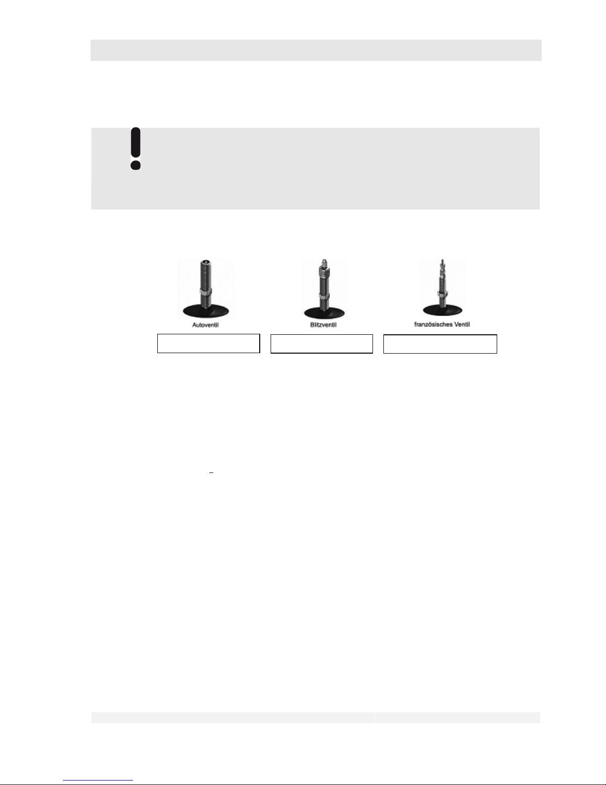
There are different valve types. All valves can be fitted with a dust cap. In the
case of a Schraeder (Auto) valve or Dunlop valve, the pump head can be
connected directly after removing the cap. In the case of a Sclaverand
(French) valve you first have to loosen the small lock nut on the valve as far
as it will go, then tighten it again completely after inflating the tyre. Have the
use of the valves explained to you by your dealer.
3. Inspect your tyres for visible signs of damage and wear:
• The tyre rubber must have its original profile over its whole surface.
• The tyre fabric under the rubber layer must not be visible.
• There must be no visible blisters or cracks.
4. Check the proper fitting of your tyres:
• Raise the front and rear wheels alternately and turn the wheel by hand.
•
The tyre must run smoothly. There must be no wobble or eccentricity.
6.1.4 Check other points
1. Inspect your wheels for loose parts such as twigs, fabric residues, loose spoke
reflectors, etc.
If any loose parts are discovered:
• Remove these if this is possible without great force.
• Check whether the wheels have been damaged by these loose parts.
• Secure loose bike parts such as spoke reflectors again. If this is not
possible, contact your dealer immediately.
• Check that all reflectors required in accordance with StVZO (see chapter
2.1.4) are fitted, correctly secured and not concealed or soiled.
Schraeder (Auto) valve
Dunlop valve
Sclaverand (French) valve
Page 38
GHOST
User Manual Status 04/2009 // Spec 2010
6.38
6.2 Inspect the saddle and saddle post
Danger of personal injury and material damage!
If the insertion depth is too short, the saddle post can come loose. This can lead
to dangerous riding situations, falls, accidents and material damage.
Pay attention to the correct insertion depth of the saddle post. Observe
the instructions in chapter 7.3.
If you have the necessary technical know-how, you can carry out this
attachment yourself.
Observe the instructions in chapters 7.2, 7.3 and 10.2.
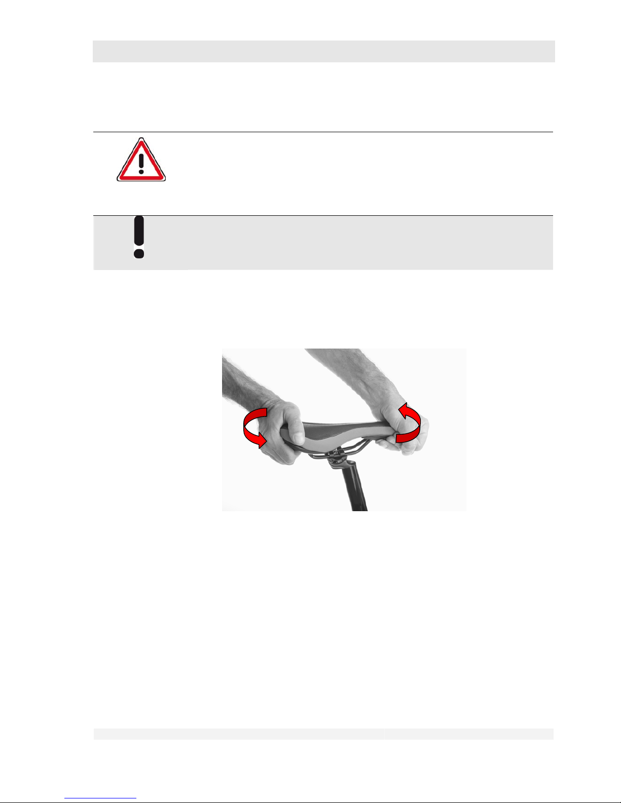
1. Check that the saddle and saddle post are securely fastened:
• Try to twist the saddle and post in the frame by hand.
It must not be possible to twist the saddle and saddle post.
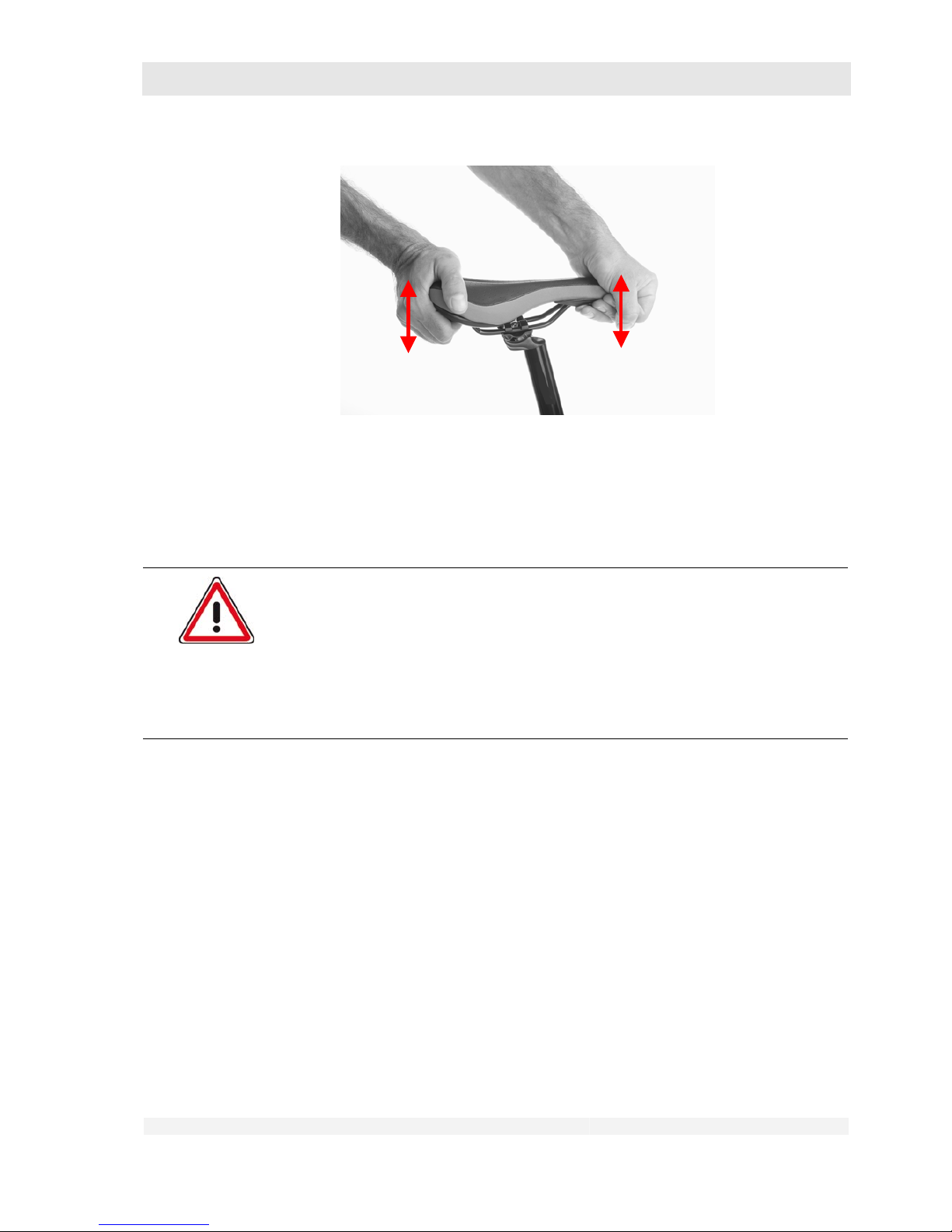
• Try to move the saddle in its clamp with your hand by alternately pushing
down and pulling up.
The saddle must not move.
Page 39
GHOST
User Manual Status 04/2009 // Spec 2010
6.39
• If saddle and/or saddle post do move,
tighten the respective bolt(s) securely (see chapters 7.2, 7.3 and 10.2).
6.3 Inspect the handlebars and handlebar stem
Danger of personal injury and material damage!
Handlebars and handlebar stem are very important components for your safety.
Damage to these parts and/or errors in installation can result in very serious
accidents.
If you discover damage to these parts or have any doubt about their
integrity, you must not use your bike again.
Contact an approved workshop immediately.
1. Check the installation of handlebars and handlebar stem.
• The handlebar stem must be parallel to the front wheel rim,
• the handlebars at right angles to the stem.
• In the case of a shaft handlebar stem, the “Max.”, “Stop” or equivalent mark
must not be visible.
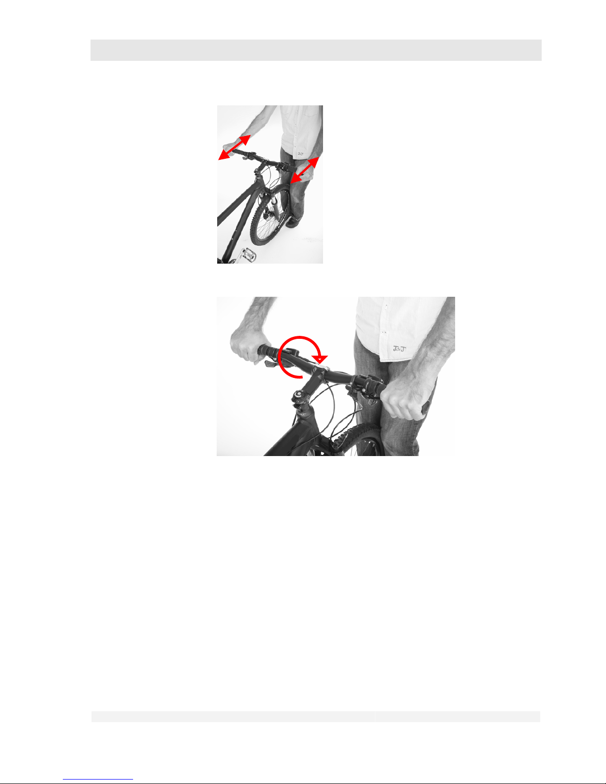
• Clamp the front wheel between your legs.
• Grip the handlebars at both ends.
• Try to twist the handlebars in both directions with your hands.
• Try to twist the handlebars in the handlebar stem with your hands.
Page 40
GHOST
User Manual Status 04/2009 // Spec 2010
6.40
• It must not be possible to move or twist any of the parts.
• No cracking or grinding noises should be heard.
6.4 Inspect the handlebar attachments
1. Check the secure attachment of the gear shift levers, brake levers and
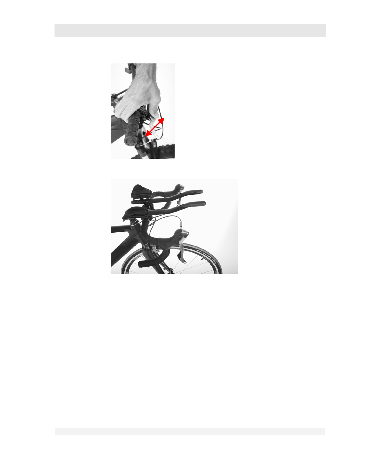
handlebar grips. A triathlon handlebar attachment and/or bar ends (“horns”)
may have been installed on your handlebars if these are permitted by the
manufacturer. Inspect these parts for proper attachment.
• Clamp the front wheel between your legs.
• Try to twist the brake levers with your hands.
Page 41
GHOST
User Manual Status 04/2009 // Spec 2010
6.41
Triathlon handlebar attachment
• Try to twist the gear shift levers with your hands.
• Try to twist the triathlon handlebar attachment with your hands.
• Try to pull the handlebar grips and the bar ends from the handlebars.
• If bar ends are correctly installed, the handlebar grip test can be waived.
• It must not be possible to move or twist any of the parts.
• No cracking or grinding noises should be heard.
• A bell (if installed) must be easily reached with finger or thumb; it must not
be possible to move the bell.
6.5 Inspect the headset
The headset is the mounting of the handlebar stem in the fork column.
1. Check your headset. It must be possible to steer the front wheel easily in both
directions without backlash:
Page 42
GHOST
User Manual Status 04/2009 // Spec 2010
6.42
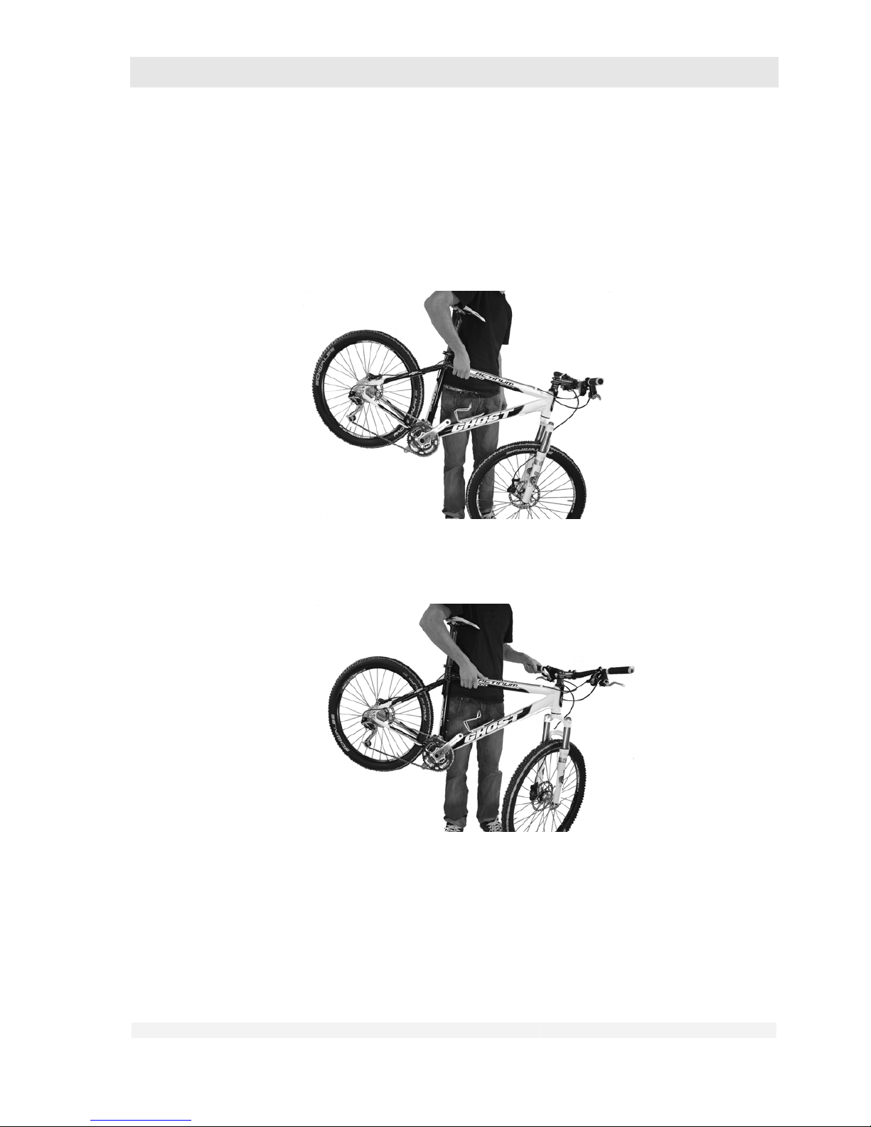
• Stand alongside your bike and hold the handlebar grips with both hands.
• Apply the front wheel brake and keep the brake applied.
• Push your bike forward and back with short, jerky movements.
• The headset must not exhibit any backlash. No cracking must be heard or
felt. Grinding noises are also not permitted.
• Pick up the whole bike so that the rear wheel is higher than the front wheel.
• Turn the front wheel to the side by means of a handlebar movement and
release it again.
• The front wheel must now move back independently into its original position.
• The front wheel must not lock in any position.
Page 43
GHOST
User Manual Status 04/2009 // Spec 2010
6.43
6.6 Inspect the spring fork
1. Check your spring fork:
• Apply the front wheel brake and keep the brake applied.
• Press with your body weight onto the handlebars so that the spring fork is
compressed.
•
The fork must move easily up and down.
•
No cracking or grinding noises should be heard.
•
(refer also to the component manufacturer’s operating instructions)
6.7 Inspect the rear wheel suspension
1. Check your rear wheel suspension:
• Sit on the saddle and alternately compress and relieve the suspension by
short up and down movements.
• The rear end of the bike must move easily up and down.
• No cracking or grinding noises should be heard.
• (refer also to the component manufacturer’s operating instructions)
6.8 Inspect the brakes
Danger of personal injury and material damage!
A brake malfunction is a serious danger to safety.
Pay particular attention when checking the brake system.
During prolonged tours over several days the brake disc, brake blocks and
brake pads can become severely worn.
Always take replacement brake blocks and replacement brake pads with you
on such tours.
Carry out the replacement yourself only if you are familiar with this work.
Please consult your dealer.
If you are not familiar with this replacement, have the work carried out in an
approved workshop.
1. Check the proper function of your brake system.
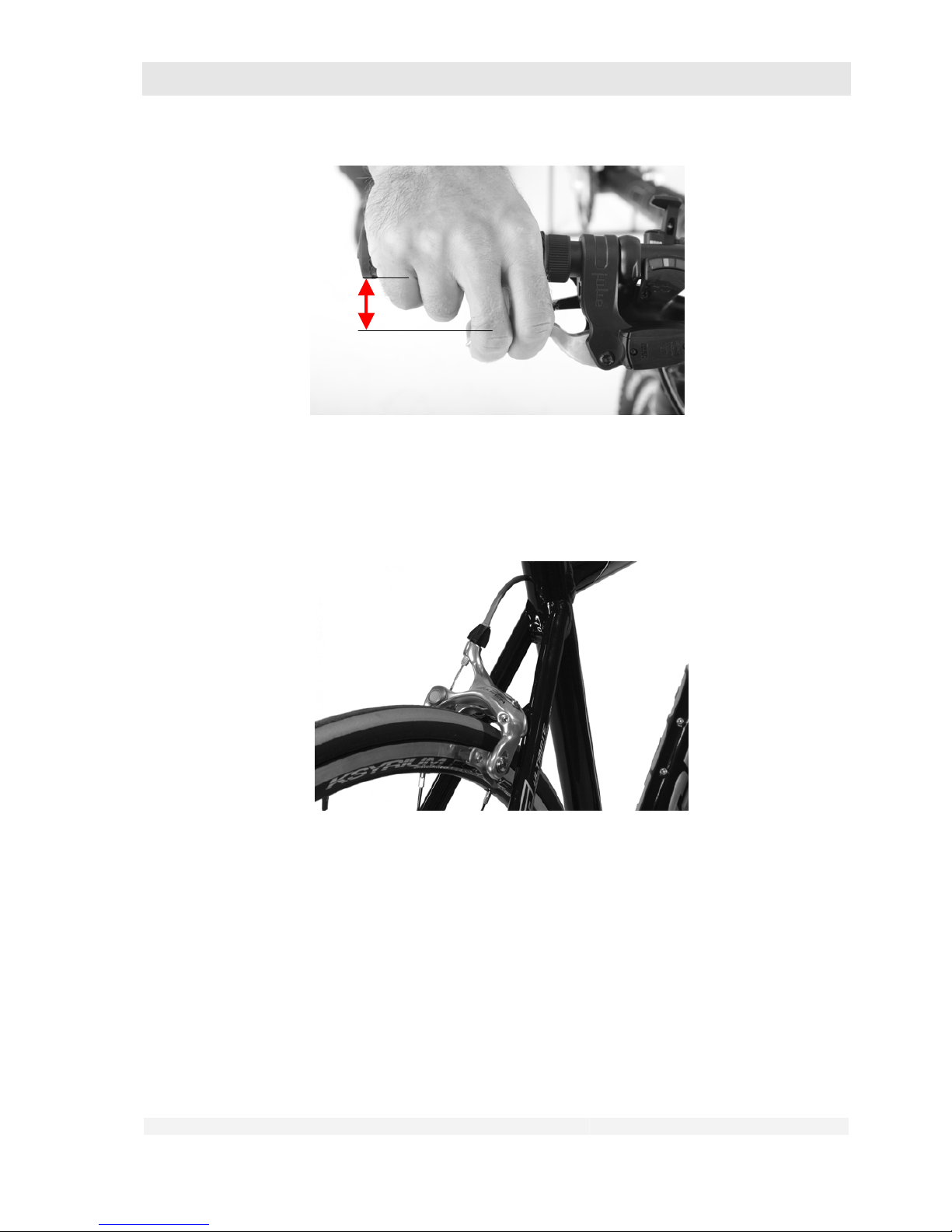
• Pull on both brake levers completely with the bike at a standstill.
• Note that in this position the minimum distance between the brake lever and
handlebar grip must still be at least 35 mm.
Page 44
GHOST
User Manual Status 04/2009 // Spec 2010
6.44
• Try to push the bike with both brakes applied.
Both wheels must remain locked.
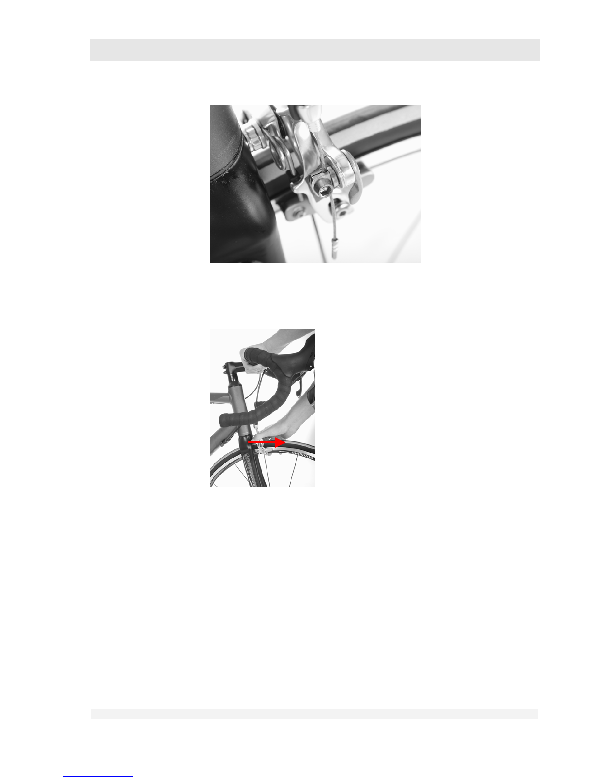
6.8.1 Check the rim brake with cable (racing bike version)
Racing bike rim brake
1. Check the brake cables and their clamps.
• The brake cables must not be damaged or corroded.
• The brake cables of cable brakes must be clamped over their full width.
Page 45
GHOST
User Manual Status 04/2009 // Spec 2010
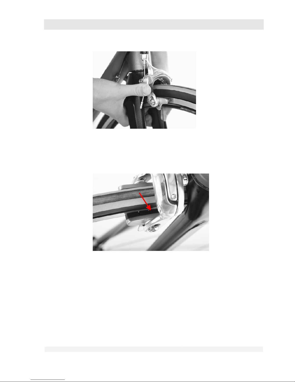
6.45
2. Check the correct mounting and bolts of the whole brake system:
• Try to pull the brakes from the fork (front) or frame (rear) with your hands.
• The brakes must remain securely attached and the mountings must not
exhibit any clearance.
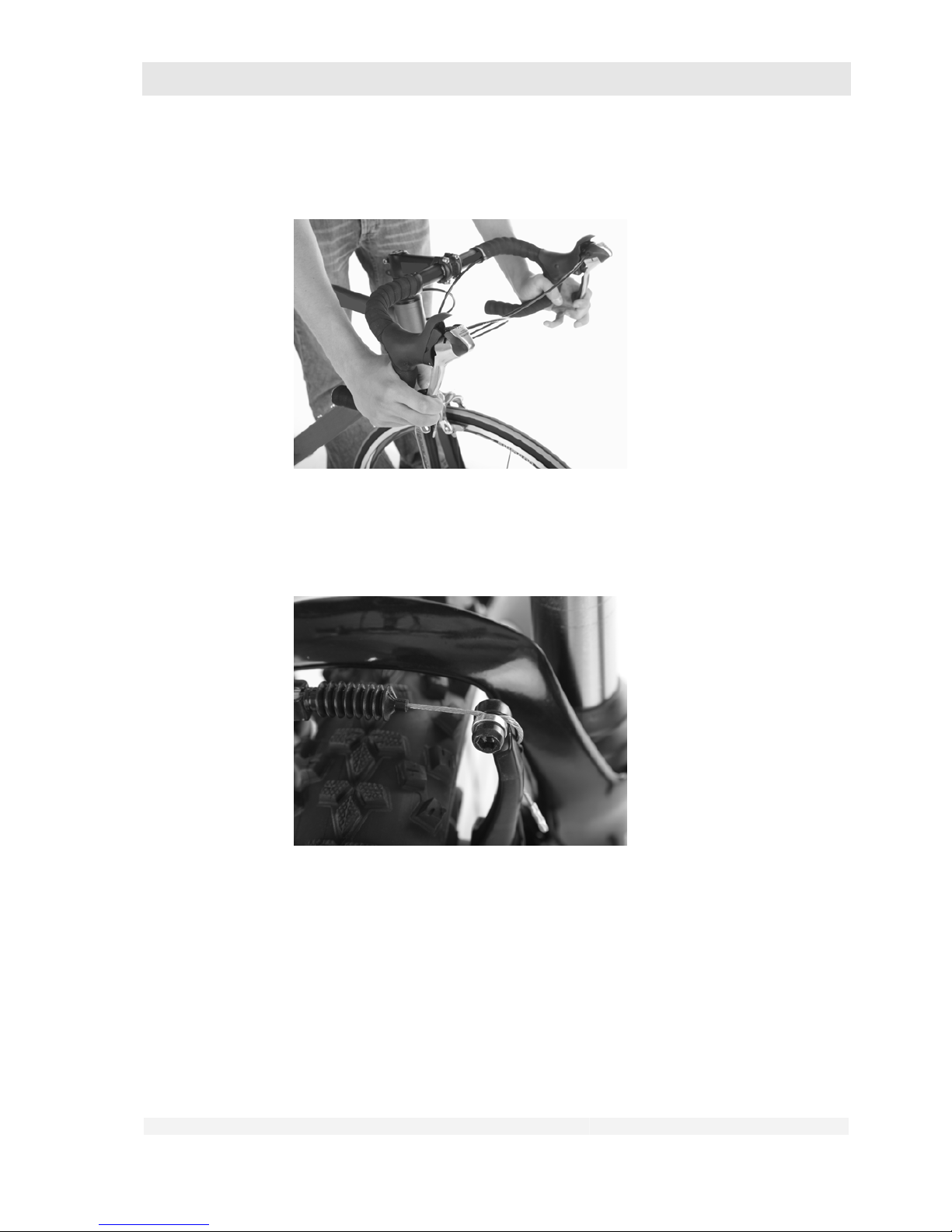
3. Check the position of the brake shoes.
• When the brakes are applied, the brake shoes must contact the rim flank
with practically their whole surface area.
Page 46
GHOST
User Manual Status 04/2009 // Spec 2010
6.46
• In no position, i.e. even when the brakes are not applied, may the brake
shoes touch the tyres.
4. Check the wear of the brake blocks.
• The brake blocks must not be worn beyond the wear indicator.
5. Check that the brakes are centered:
The brake shoes must have the same distance to the rim on both sides.
Page 47
GHOST
User Manual Status 04/2009 // Spec 2010
6.47
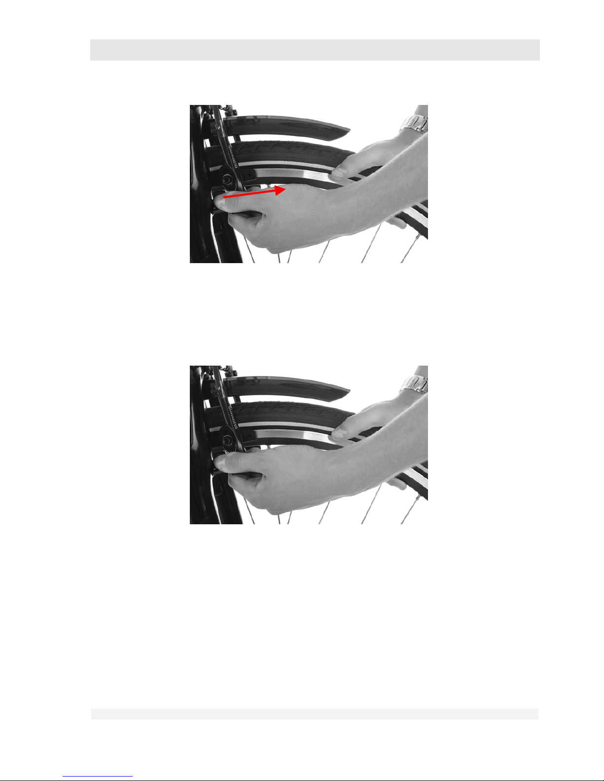
6.8.2 Check the rim brake with cable (MTB version)
1. Check the brake cables and their clamps:
• The brake cables must not be damaged or corroded.
• The brake cables of cable brakes must be clamped over their full width.
2. Check the correct mounting and bolts of the whole brake system:
• Try to pull the brakes out of the shoes with your hands.
Page 48
GHOST
User Manual Status 04/2009 // Spec 2010
6.48
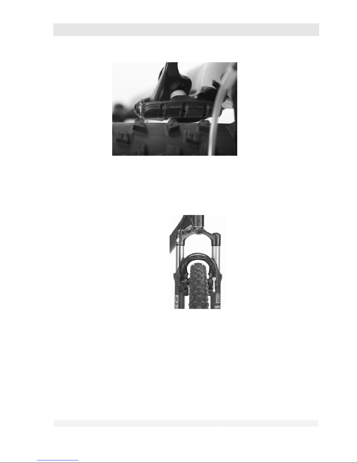
• It must not be possible to pull the brakes blocks out of the shoes by hand. A
slight backlash is normal.
3. Check the position of the brake shoes.
• When the brakes are applied, the brake shoes must contact the rim flank
with practically their whole surface area.
• In no position, i.e. even when the brakes are not applied, may the brake
shoes touch the tyres.
4. Check the wear of the brake blocks.
• Unhook the brakes for the inspection (see chapter 10.1).
• The brake blocks must not be worn beyond the wear indicator.
Page 49
GHOST
User Manual Status 04/2009 // Spec 2010
6.49
5. Check that the brakes are centered:
• The brake shoes must have the same distance to the rim on both sides.
6.8.3 Check the hydraulic rim brakes
1. Check the correct mounting and bolts of the whole brake system:
• Try to pull the brakes out of the shoes with your hands.
• It must not be possible to pull the brakes blocks out of the shoes by hand. A
slight backlash is normal.
2. Check your brake system for leaks:
• Pull the respective brake lever with the bike at a standstill and hold the
brake lever in this position.
• Inspect the brake system from the brake lever along the lines up to the
brakes.
• No hydraulic fluid should escape at any point.
Page 50
GHOST
User Manual Status 04/2009 // Spec 2010
6.50
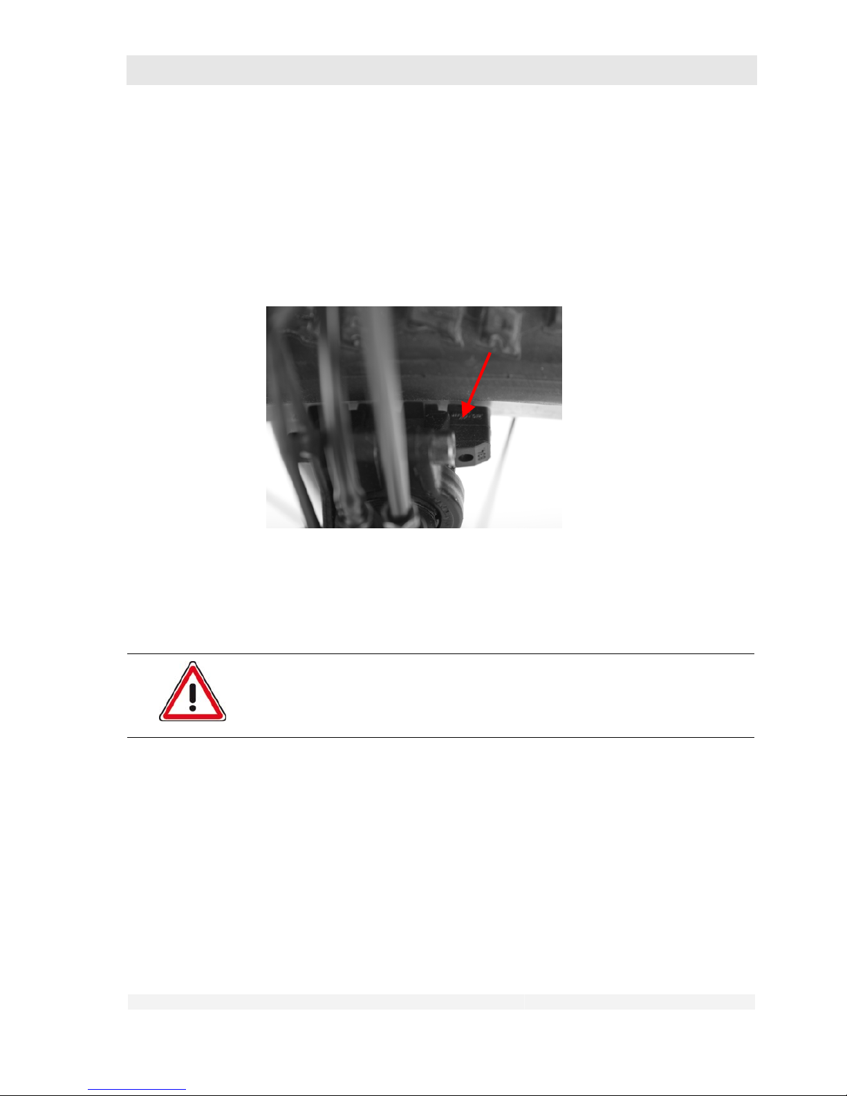
3. Check the position of the brake shoes:
• When the brakes are applied, the brake shoes must contact the rim flank
with practically their whole surface area.
• In no position, i.e. even when the brakes are not applied, may the brake
shoes touch the tyres.
4. Check the wear of the brake blocks:
• The brake blocks must not be worn beyond the wear indicator.
5. Check that the brakes are centered:
• The brake shoes must have the same distance to the rim on both sides.
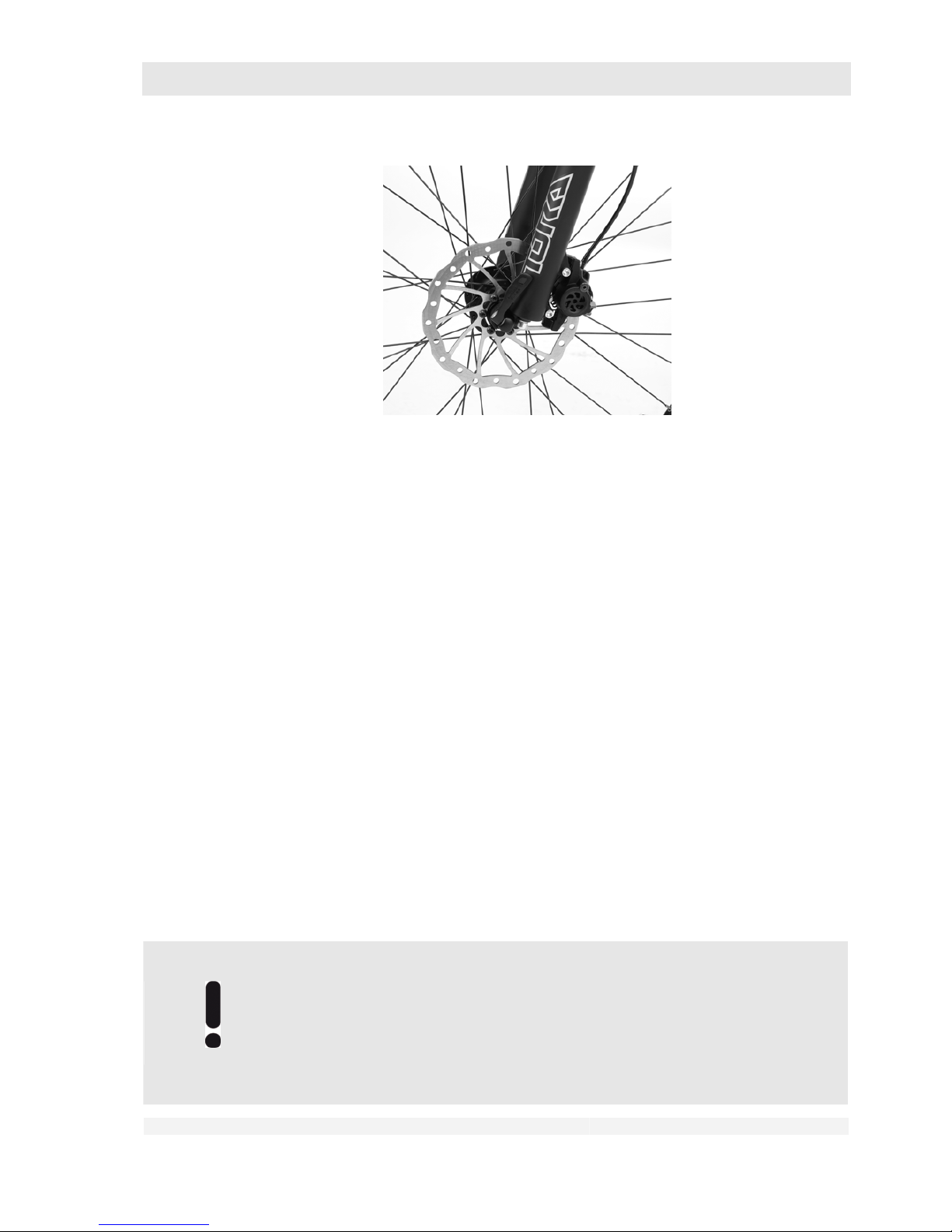
6.8.4 Check the hydraulic disc brake
Danger of personal injury and material damage!
Soiled brake discs can impair the braking effect.
Soiled brake discs must be cleaned immediately
Page 51
GHOST
User Manual Status 04/2009 // Spec 2010
6.51
1. Pull the brake calliper alternately in all directions with your hands.
• The brake calliper must not move.
2. Check your brake system for leaks:
• Pull the respective brake lever with the bike at a standstill and hold the
brake lever in this position.
• Inspect the brake system from the brake lever along the lines up to the
brakes.
• No hydraulic fluid should escape at any point.
3. Inspect the brake disc for damage:
• It must not exhibit any dents, cracks, deep scratches or other mechanical
damage.
4. Raise the front and rear wheels alternately and turn the wheel by hand:
• The brake disc may only have a minimal lateral runout.
5. Have the wear of the brake pads and brake disc checked in an approved
workshop (see also chapter 11):
• The brake pads must not be worn beyond the wear indicator.
• The thickness of the brake disc must not be below the specified minimum.
• For the minimum thickness, please refer to the enclosed component
instruction manual.
6. Inspect the brake discs for soiling, in particular for oil or grease.
• Soiled brake discs must be cleaned immediately (see chapter 11).
During prolonged tours over several days the brake disc, brake blocks and
brake pads can become severely worn.
Always take replacement brake blocks and replacement brake pads with you
on such tours.
Carry out the replacement yourself only if you are familiar with this work.
Please consult your dealer.
Page 52
GHOST
User Manual Status 04/2009 // Spec 2010
6.52
If you are not familiar with this replacement, have the work carried out in an
approved workshop.
6.8.5 Check the back-pedal brake
1. Ride at walking pace
2. Pedal “backwards” against the driving direction.
3. The rear wheel must be sharply braked.
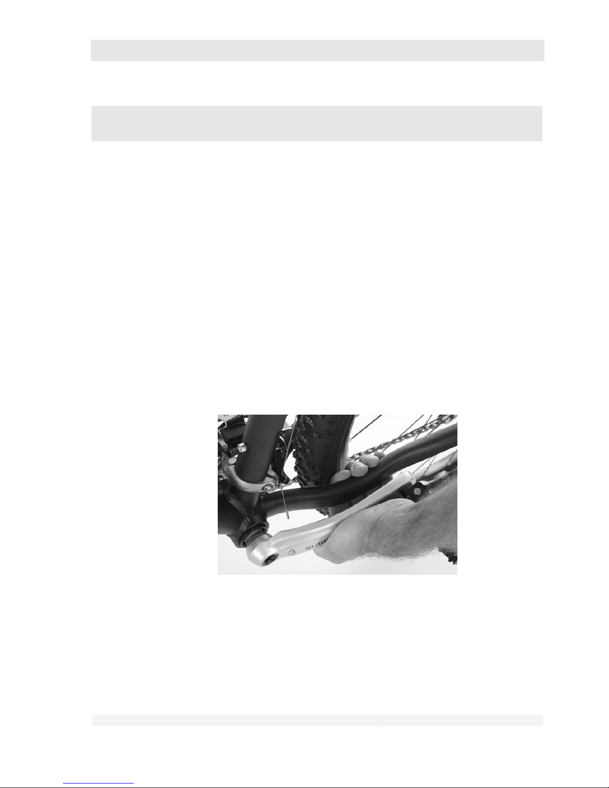
6.9 Inspect the drive and chain
1. Turn the right-hand pedal arm in anti-clockwise direction and observe the
chainwheels and the sprocket assembly from above.
• The chainwheels and sprockets must not have any lateral runout.
• There must not be any foreign matter in any of the components. Remove
any such foreign matter, if easily possible.
2. Press the left-hand pedal arm towards the chain run in the position shown.
• You should not feel any bearing backlash.
• No cracking or grinding noises should be heard.
3. Inspect the chain for damage:
• The chain must not be damaged at any point, e.g. by bent chain links,
protruding chain link pins, etc. or jammed and immobile chain links.
Page 53
GHOST
User Manual Status 04/2009 // Spec 2010
6.53
4. With the bike at standstill, turn the right-hand pedal lever contrary to the drive
direction and observe the chain run at the derailleur rollers of the rear derailleur.
5. The chain must run smoothly over the derailleur rollers and must not jump.
6.10 Inspect the lighting system
Danger of personal injury and material damage!
Failure of the headlight and rear light can lead to dangerous riding situations in
the dark or with poor visibility.
Use your bike in such visibility situations only when the lighting system
is fully functional.
1. Check the proper function of your lighting system:
• If installed, check the ON/OFF switch on the headlight.
• Lift the front wheel.
• Rotate the front wheel vigorously by hand.
• The headlight and rear light must come on.
• If installed, check the function of the rear parking light.
6.11 Inspect the luggage rack
Danger of personal injury and material damage!
Loose or hanging parts of the luggage rack can jam the wheel and result in
serious falls or accidents.
Use your bike again only when the luggage rack has been properly
secured in an approved workshop.
1. Shake the luggage rack at right angles to the direction of travel with your hands.
The luggage rack mountings must not come loose. The luggage rack must not
touch the tyres.
2. Observe the maximum load (see chapter 7.11).
6.12 Inspect the mudguards
Danger of personal injury and material damage!
Loose or hanging parts of the mudguards can jam the wheels and result in
serious falls or accidents.
Page 54
GHOST
User Manual Status 04/2009 // Spec 2010
6.54
Use your bike again only when the luggage rack has been properly secured in
an approved workshop.
1. Check the mounting of your mudguards.
• The mudguard and its mounting struts must not be bent or damaged.
• Move the front wheel sharply to left and right using the handlebars with the
bike at standstill.
• Tilt the whole bike back and forth several times at right angles to the
direction of travel.
• The mudguard mounting struts must not come loose.
• No part of the mudguards may touch the wheels.
6.13 Check other points
Danger of personal injury and material damage!
A side stand can lead to serious falls when riding if folded down.
Always fold up the side stand before riding.
1. Check your side stand, if installed.
• Carry out a visual inspection of the mounting bolt. The side stand must be
securely attached to the frame.
• Always fold up the side stand before riding. The stand must remain in this
position even in the event of vibrations.
Danger of personal injury and material damage!
Incorrectly mounted or loose accessories can impair your riding safety.
Check all accessories not expressly mentioned here for correct
mounting.
1. Check any accessories installed later by your dealer.
• Carry out a visual inspection of the mounting bolts.
• Try to twist or move the accessories with your hands.
• Tilt the whole bike back and forth several times at right angles to the
direction of travel.
• The accessories must not slip, twist or come loose.
• No part of the accessories may touch the wheels.
Page 55
GHOST
User Manual Status 04/2009 // Spec 2010
6.55
Danger of personal injury and material damage!
Damaged bike parts can have sharp edges that could cause injuries.
Check all parts of the bike with which you could come into contact while
riding.
Have any damaged parts repaired or replaced immediately in an
approved workshop.
Page 56
GHOST
User Manual Status 04/2009 // Spec 2010
7.56
7 Adjusting and Operating the Bike
The parts described below are not installed on all bikes.
Check in chapter 4 and with the aid of the following illustrations which
equipment and operating elements your bike has.
If you are not sure about anything or have any questions, please contact your
dealer.
You may carry out certain adjustments on your bike yourself. Carry out this work only when you
have the necessary basic technical knowledge, experience and appropriate tools.
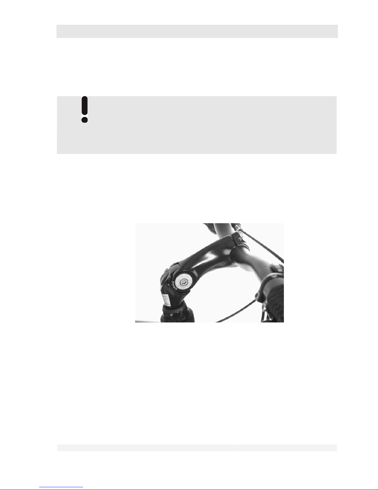
7.1 Adjust the adjustable handlebar stem (option)
Some bikes are equipped with a handlebar stem that is adjustable in height and angle. Have the
adjustment carried out only in an approved workshop!
7.2 Adjust the saddle position
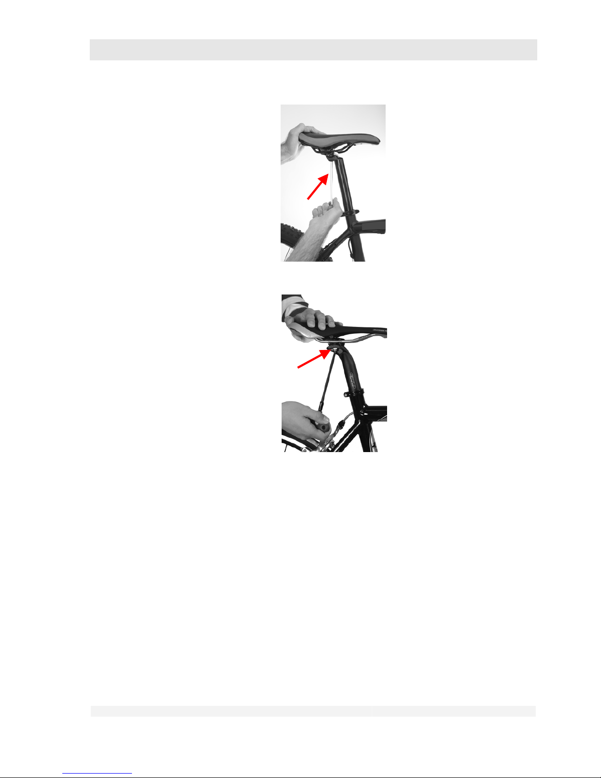
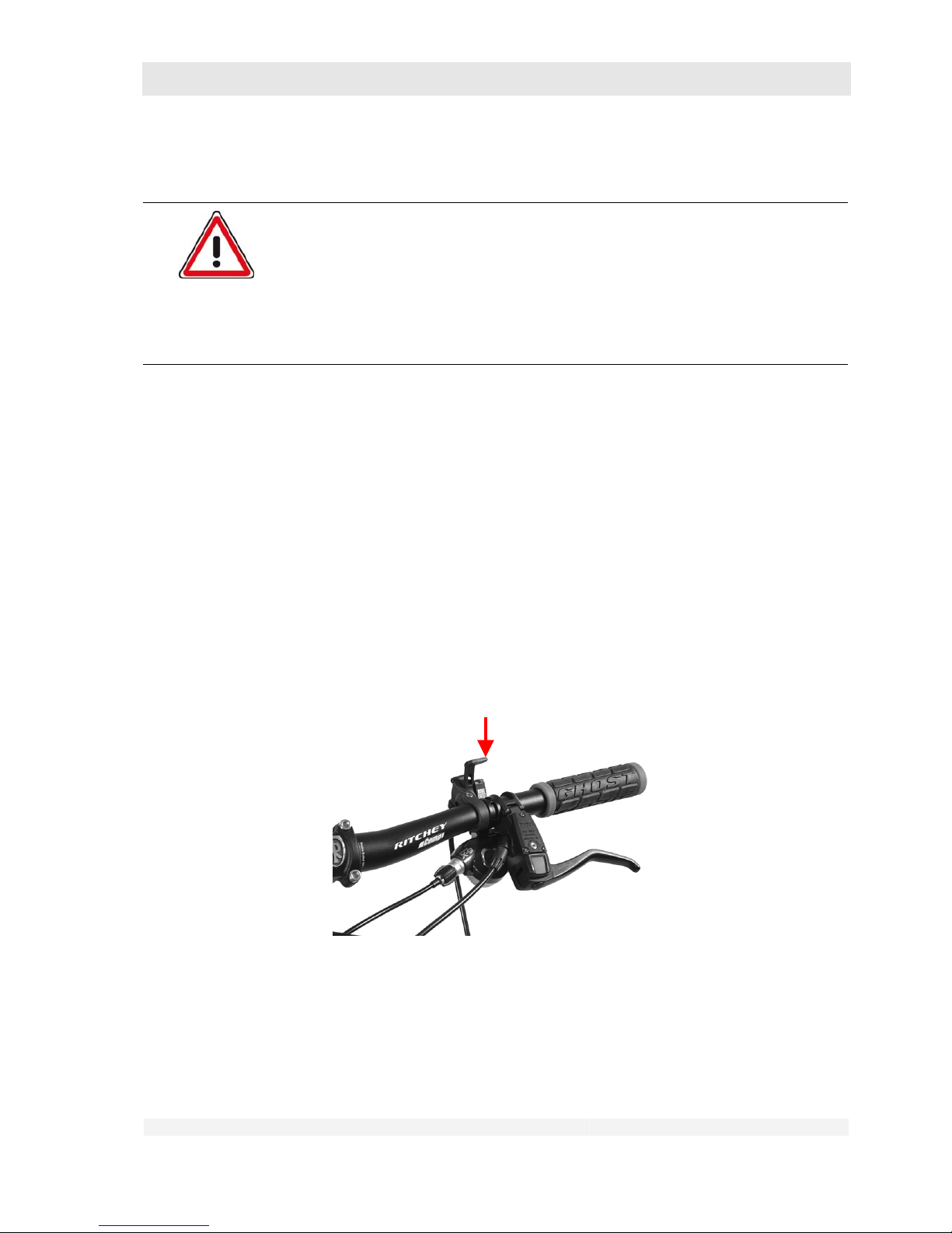
You saddle is secured with one or two clamping bolts.
For adjustment you need an Allen key and a torque wrench of the appropriate size.
1. Adjusting the horizontal position or angle of your saddle:
• Loosen the clamping bolt(s) by a few turns until the saddle can be moved
easily and/or the angle can be easily adjusted.
Page 57
GHOST
User Manual Status 04/2009 // Spec 2010
7.57
Move the saddle to the desired position.
• For saddle clamps with one bolt: Tighten the clamping bolt to the prescribed
torque again. Ensure that all loosened parts engage with one another again
correctly.
• For saddle clamps with two bolts: Turn the bolts alternately by a quarter to
half a turn until the prescribed torque is reached.
• For details of the prescribed tightening torque, please refer to the table in
chapter 3.2.
• Different tightening torques may be specified for some saddle posts. If these
are not listed in the table or directly on the saddle post, please contact your
dealer.
Page 58
GHOST
User Manual Status 04/2009 // Spec 2010
7.58
7.3 Adjust the saddle height
Danger of personal injury and material damage!
With children, and particularly those who do not yet have a complete command
of bike riding, adjustment of the saddle too high can can lead to dangerous
riding situations, falls, accidents and material damage.
Adjust the saddle height such that the child can touch the ground with
both feet when sitting on the saddle. Observe also the instructions in
chapter 10.2.
For a saddle clamp with bolt you need an Allen key and a torque wrench of the appropriate size for
the saddle adjustment.
For a saddle clamp with quick-release lever, observe the instructions in chapter 7.9.
1. Loosen the clamp as described in chapter 10.2.
2. Move the saddle with saddle post to the desired position. Observe the
information on the insertion depth of the saddle post in chapter 10.2.
3. Clamp the saddle post as described in chapter 10.2.
7.4 Adjust the spring fork
1. For details of adjusting the spring fork, please refer to the component user
manual from the spring fork manufacturer supplied with the bike.
Lockout
2. If your fork has a locking mechanism as shown in the figure, please refer to the
component user manual from the spring fork manufacturer supplied with the
bike for details of operation.
Page 59

GHOST
User Manual Status 04/2009 // Spec 2010
7.59
Spring forks with elastomer and/or steel springs are suitable only for one total
weight range (= weight of rider + any luggage). This weight range normally lies
within 20 kg.
Only the preload on the fork can be adjusted by compressing the springs
using adjusting screws. This merely alters the breakaway torque of the fork,
i.e. with a higher preload the fork is compressed only under higher working
loads.
If the fork preload is set too high, the spring travel is shortened
correspondingly.
For details of the weight range of the spring elements in your spring fork,
please refer to the user manual from the spring fork manufacturer supplied
with the bike and/or contact your dealer.
If your total weight is outside this range, have the appropriate spring elements
for your weight installed by your dealer.
7.5 Adjust the rear wheel suspension
(with full-suspension bikes – “Fullies”)
1. For details of adjusting the spring/damper element, please refer to the
component user manual from the manufacturer supplied with the bike. Please
consult your dealer.
2. Adjust your spring/damper element so that the bike drops equally at the front
and rear wheel when loaded with the rider’s weight (see also the enclosed
damper pressure recommendations).
7.6 Operating the gear shift
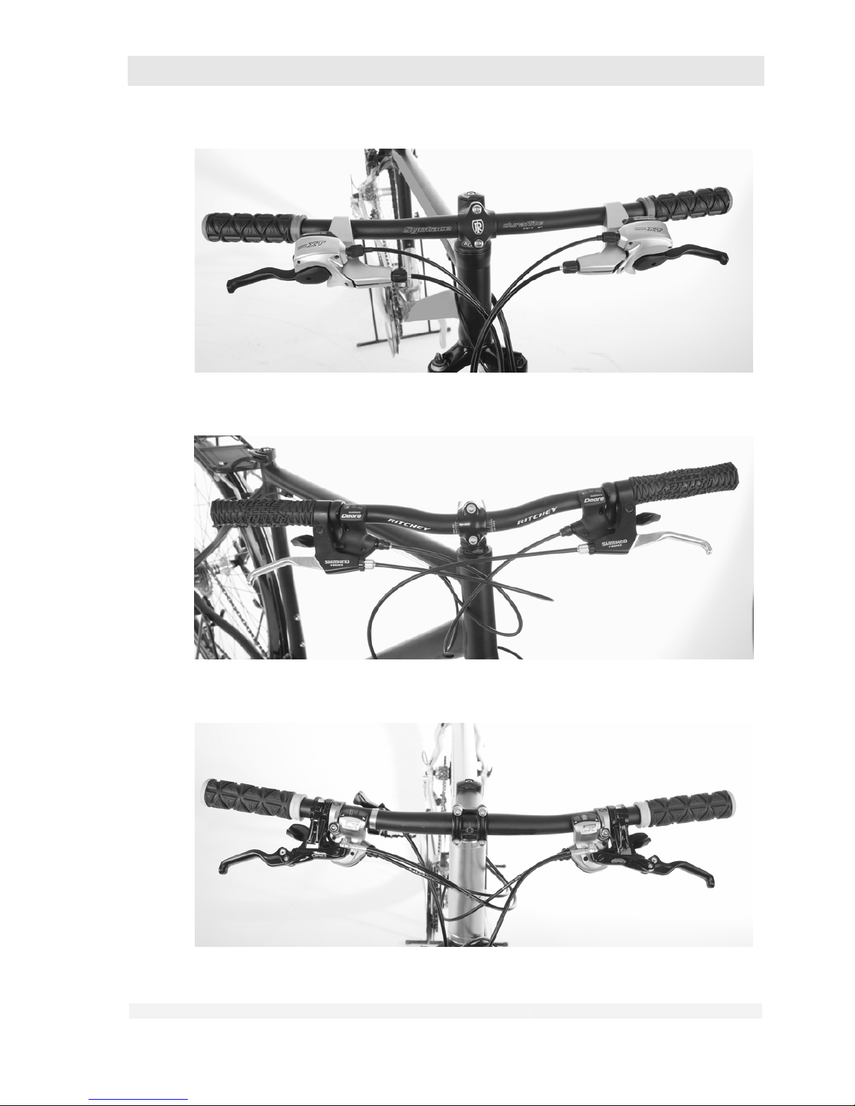
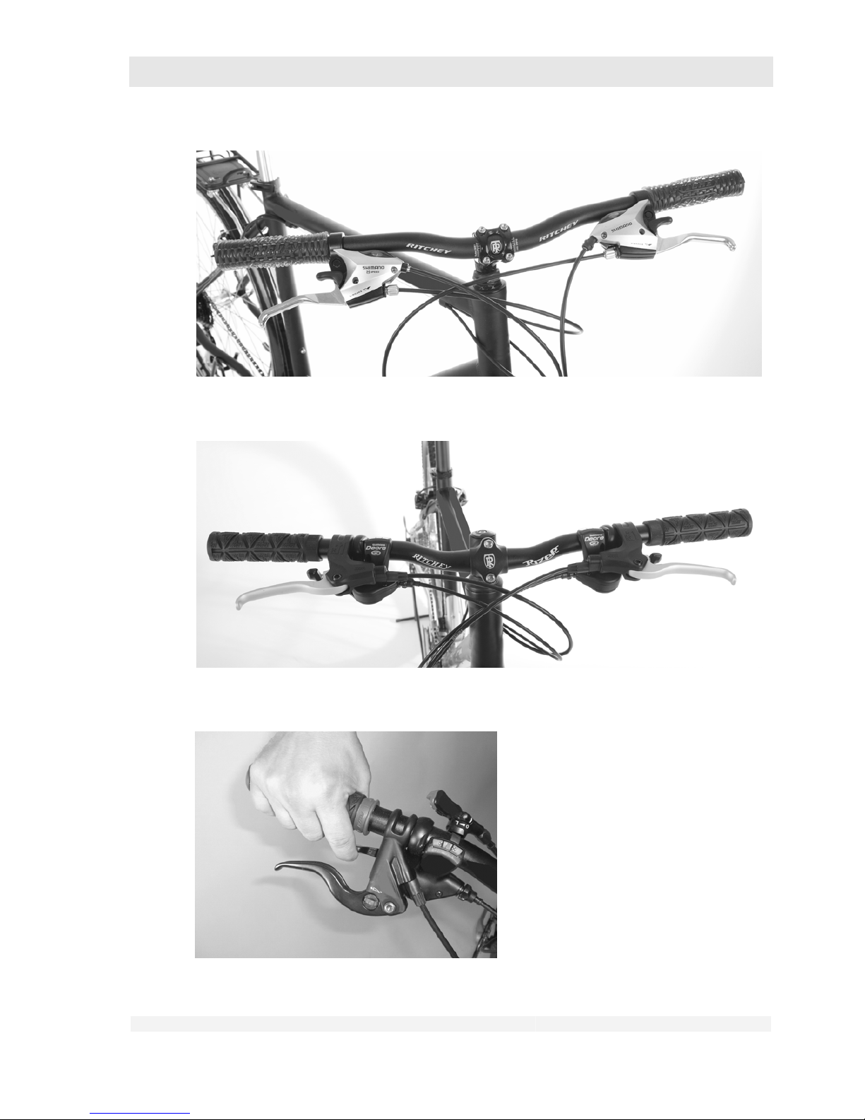
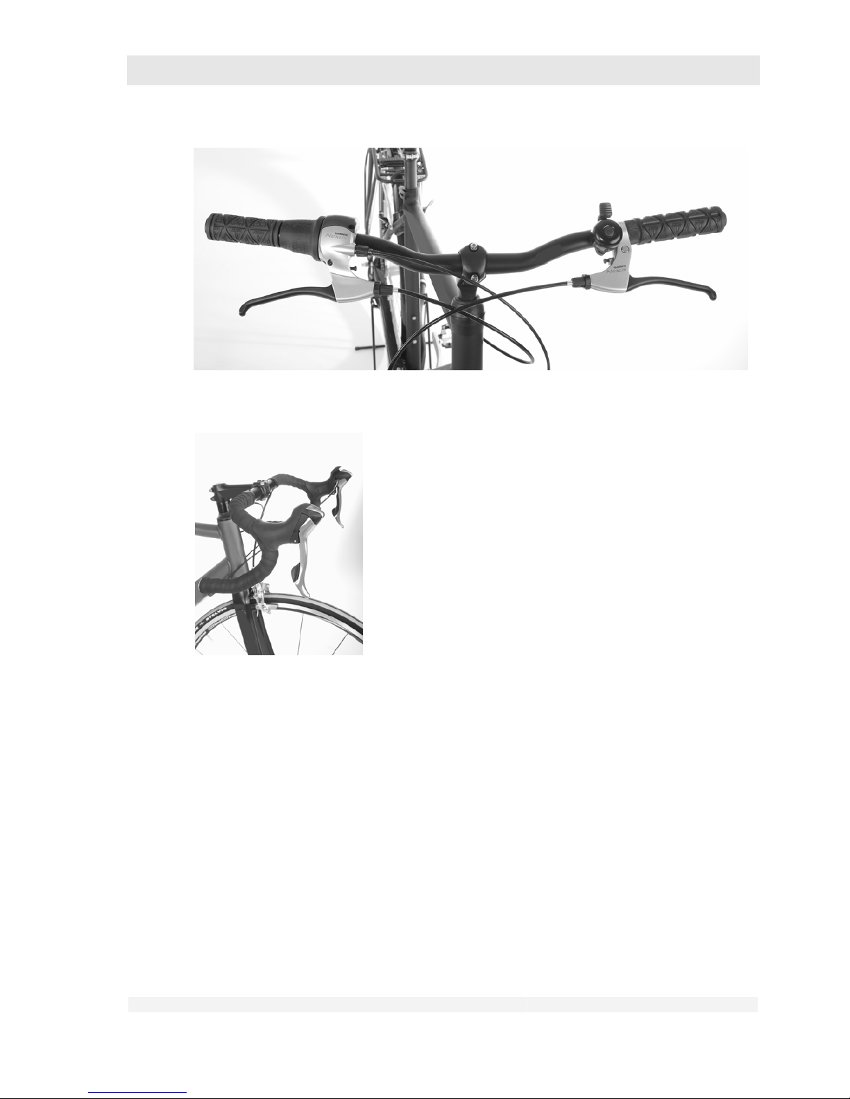
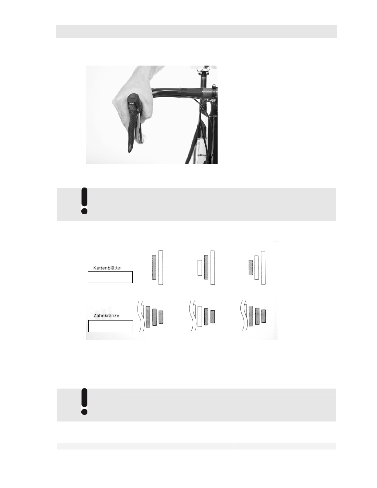
1. Please identify the gear shift system installed on your bike using the figures. If
you are not sure about the type, please consult your dealer.
2. If your gear shift lever is not illustrated in the figures, please consult the
component user manual from the shift lever manufacturer supplied with the bike
and/or contact your dealer.
Page 60
GHOST
User Manual Status 04/2009 // Spec 2010
7.60
Shimano Dual Control
Shimano Rapidfire 2-way release
Shimano Rapidfire 2-way release
Page 61
GHOST
User Manual Status 04/2009 // Spec 2010
7.61
Shimano EZ Fire
Shimano Rapidfire
Shimano Rapidfire
Page 62
GHOST
User Manual Status 04/2009 // Spec 2010
7.62
Twist grip switch
Shimano STI
Page 63
GHOST
User Manual Status 04/2009 // Spec 2010
7.63
Sram Force / Rival / Red
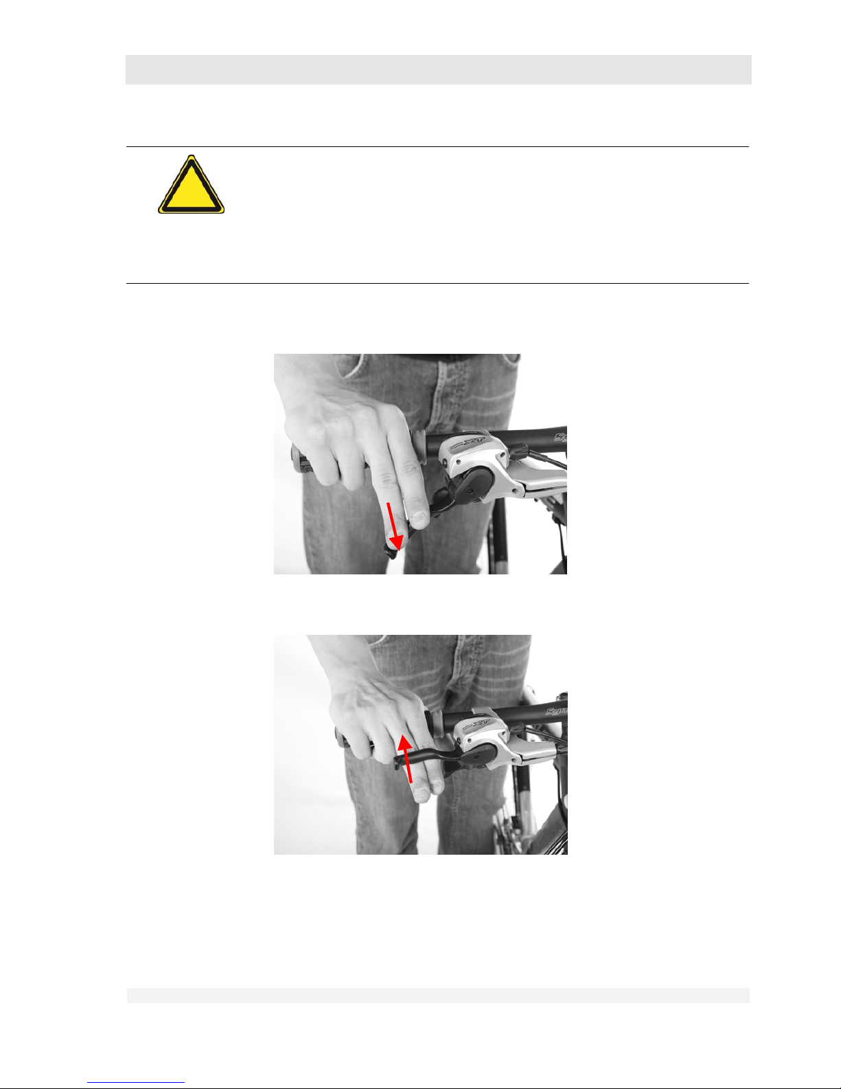
With a derailleur gear system the gears are changed by shifting the chain to
another sprocket. At the pedal cranks these sprockets are referred to as
“chainwheels”, at the sprocket assembly “pinions”.
• The combinations shown in grey result in increased noise development and
material wear and should generally be avoided.
• Avoid: Largest chainwheel + largest pinion
• Smallest chainwheel + smallest pinion
The left-hand lever is used to operate the front derailleur, the right-hand lever
to operate the rear derailleur.
Chainwheels
Sprockets
Page 64
GHOST
User Manual Status 04/2009 // Spec 2010
7.64
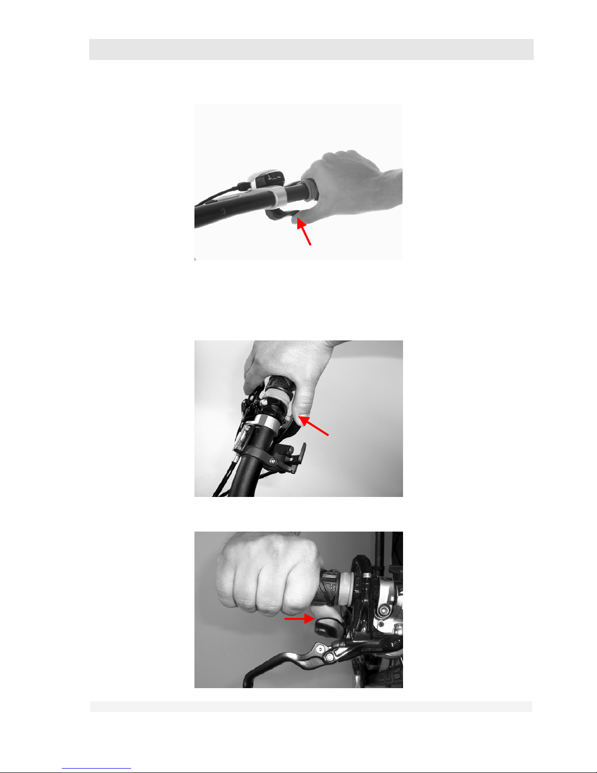
Danger of material damage!
Incorrect operation of the gear shift levers can damage your drive components.
Never operate both shift levers or both switches at the same time!
Applies to switches on the crank assembly (left-hand switch) and hub gear:
Never change gear under load!
Page 65
GHOST
User Manual Status 04/2009 // Spec 2010
7.65
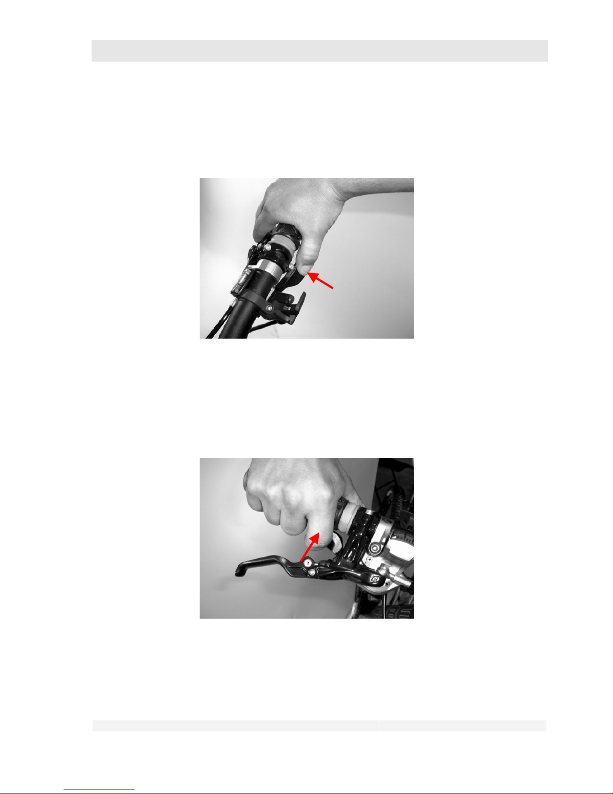
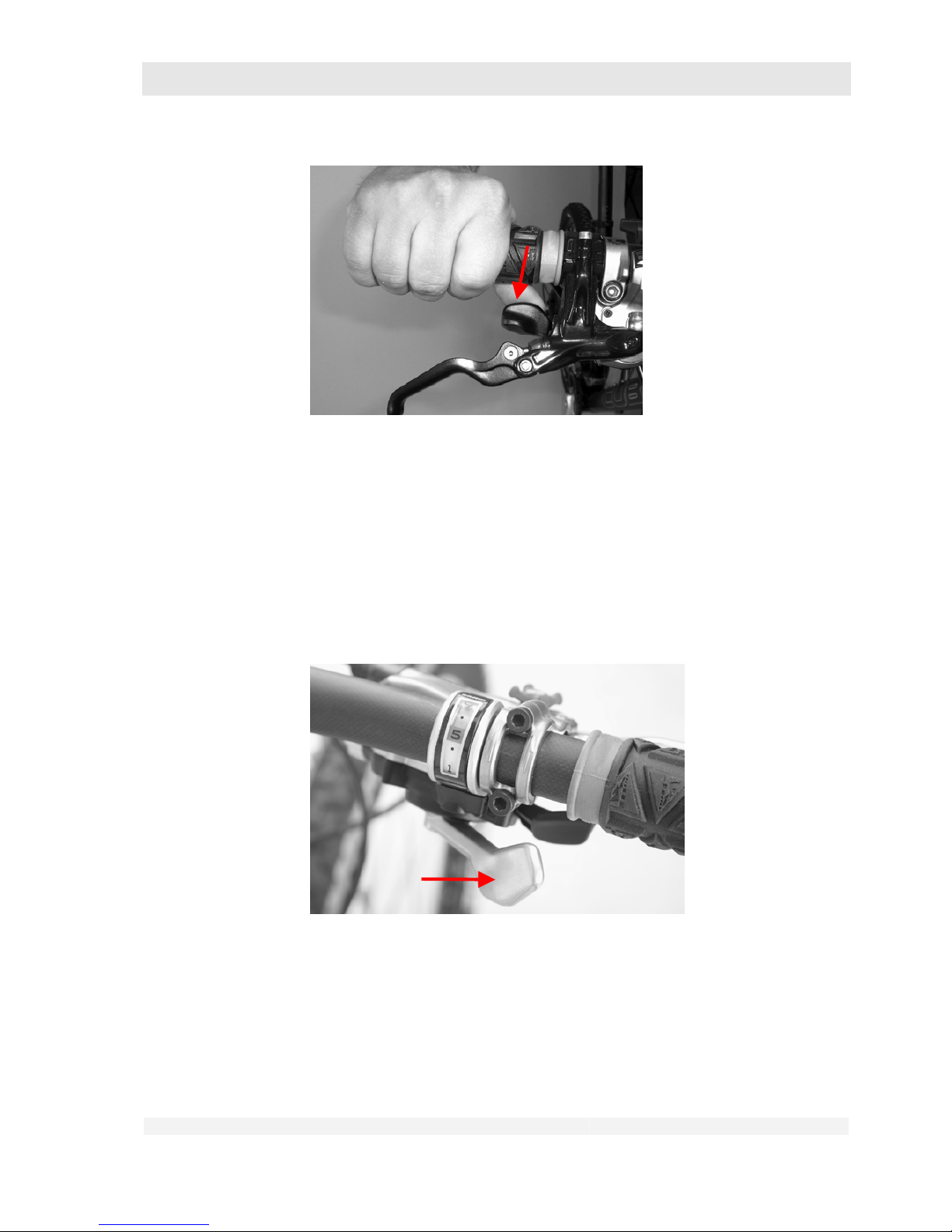
7.6.1 Shimano Rapidfire/ Shimano Rapidfire 2-Way Release/Shimano EZ Fire
Your gear shift has two levers. Lever A is used to shift to a larger chainwheel or pinion, lever B to a
smaller chainwheel or pinion.
Lever A
Lever B
Page 66
GHOST
User Manual Status 04/2009 // Spec 2010
7.66
1. Shifting to a larger sprocket:
• You must pedal while shifting.
• Press the lever with your thumb beyond the first locking step and hold it
pressed until the desired gear is engaged.
• For faster shifting over several sprockets, press the lever completely
forward and hold it pressed until the desired gear is engaged.
2. Shifting to a smaller sprocket:
• You must pedal while shifting.
• Press (only with 2-way release) or pull lever B until you feel an engagement
and then release the lever again immediately.
Page 67
GHOST
User Manual Status 04/2009 // Spec 2010
7.67
7.6.2 Sram MTB
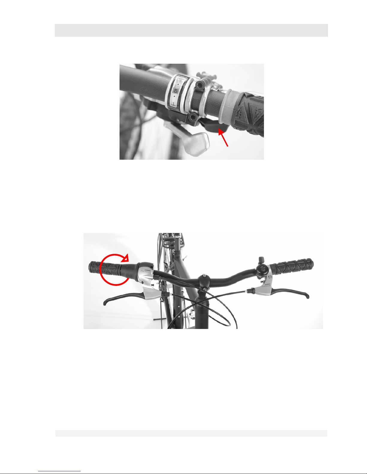
Your gear shift has two levers. Lever A is used to shift to a larger chainwheel or pinion, lever B to a
smaller chainwheel or pinion.
1. Shifting to a larger sprocket:
• You must pedal while shifting.
• Press the lever with your thumb beyond the first locking step and hold it
pressed until the desired gear is engaged.
• For faster shifting over several sprockets, press the lever completely
forward and hold it pressed until the desired gear is engaged.
2. Shifting to a smaller sprocket:
• You must pedal while shifting.
• Press lever B until you feel an engagement and then release the lever again
immediately.
A
Page 68
GHOST
User Manual Status 04/2009 // Spec 2010
7.68
7.6.3 Twist grip switch
Your switch grip has a ring that can be rotated in both directions. You shift to the next gear by
rotating this ring. Depending on the manufacturer, twisting in the same direction may select a
higher or lower gear. For details of the exact function, please consult the component user manual
supplied with the bike and/or contact your dealer.
1. Shifting with a hub gear:
• Do not pedal while shifting.
• Turn the ring in the desired direction until the gear is engaged.
2. Shifting to a larger sprocket with a dérailleur:
• You must pedal while shifting.
• Turn the shift ring until the desired gear is engaged.
• For faster shifting over several sprockets, turn the shift ring until the desired
gear is engaged.
3. Shifting to a smaller sprocket:
B
Page 69
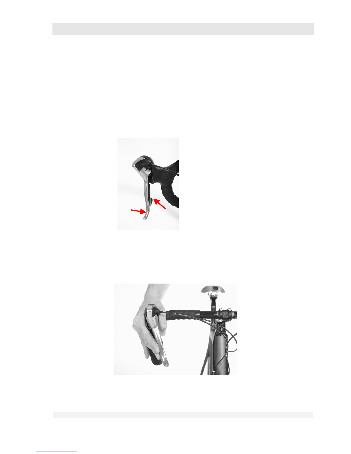
GHOST
User Manual Status 04/2009 // Spec 2010
7.69
• You must pedal while shifting.
• Turn the shift ring until the desired gear is engaged.
• For faster shifting over several sprockets, turn the shift ring until the desired
gear is engaged.
7.6.4 Shimano STI (on RACE Series only)
Your gear shift has two levers. Lever A – this is also the brake lever – is used to shift to a larger
chainwheel or pinion, lever B to a smaller chainwheel or pinion.
1. Shifting to a larger sprocket:
• You must pedal while shifting.
• Press lever A beyond the first locking step and hold it pressed until the
desired gear is engaged.
• For faster shifting over several sprockets, press lever A completely forward
and hold it pressed until the desired gear is engaged.
A
B
Page 70
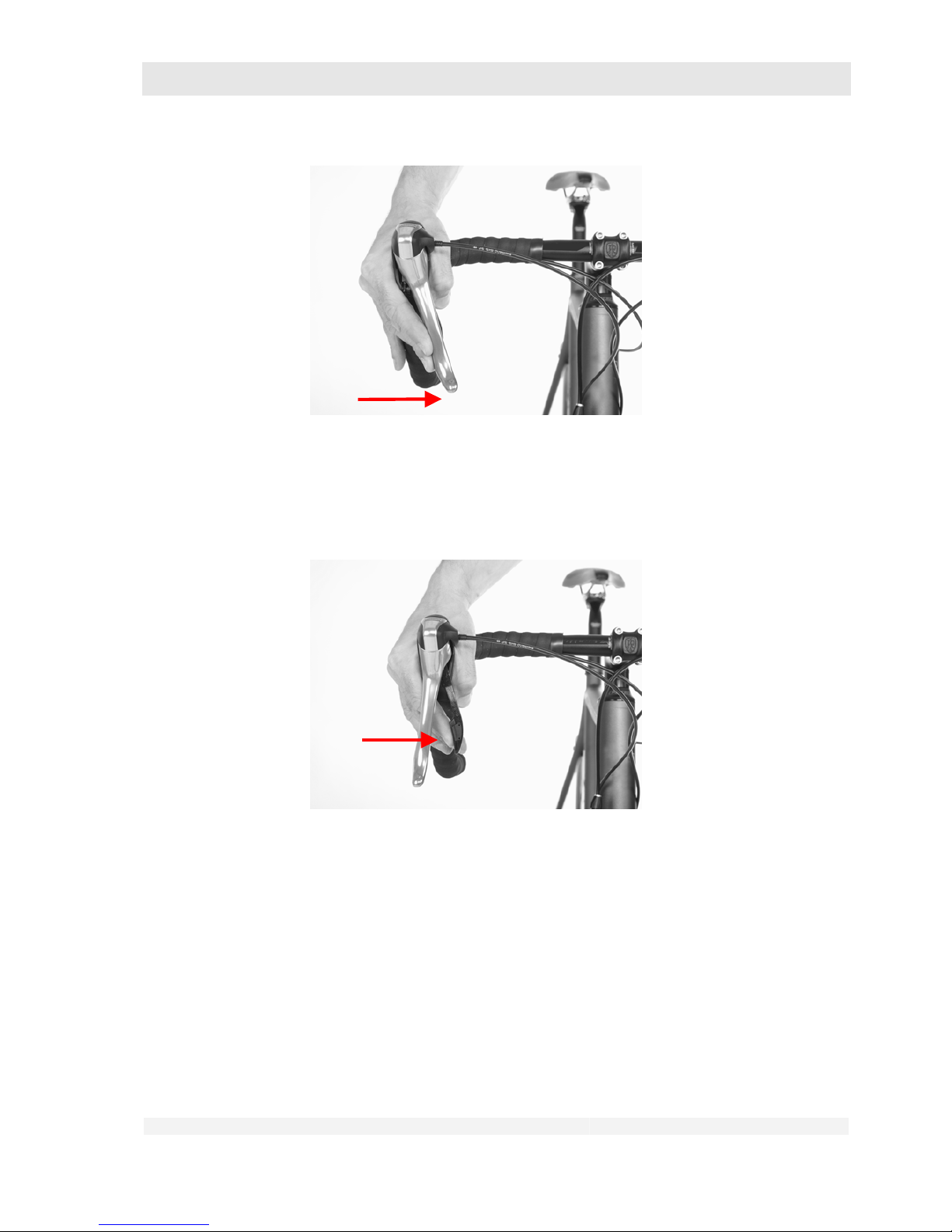
GHOST
User Manual Status 04/2009 // Spec 2010
7.70
2. Shifting to a smaller sprocket:
• You must pedal while shifting.
• Press lever B until you feel an engagement and then release the lever again
immediately.
7.6.5 Sram Force / Rival / Red (on RACE Series only)
Your shift/brake lever has a lever with which you can shift to both a higher and a lower gear.
This can be pressed inwards for shifting.
1. Shifting to a larger sprocket:
• You must pedal while shifting.
• Press the shift lever inwards and hold it pressed until the desired gear is
engaged.
• For faster shifting over several sprockets, press the lever completely
inwards and hold it pressed until the desired gear is engaged.
A
B
Page 71
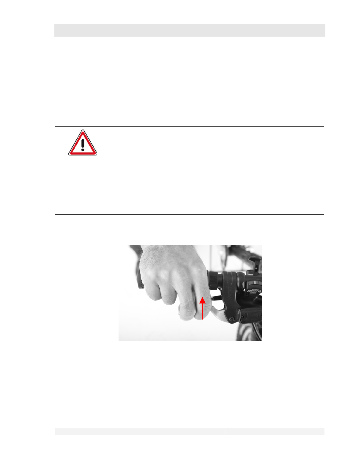
GHOST
User Manual Status 04/2009 // Spec 2010
7.71
2. Shifting to a smaller sprocket:
• You must pedal while shifting.
• Press the lever until you feel an engagement and then release the lever
again immediately.
7.7 Using the brakes
Danger of personal injury and material damage!
Incorrect use of the brakes can lead to dangerous riding situations, falls,
accidents and material damage.
Familiarise yourself with the use of the brakes.
Find out which brake lever actuates the front wheel brake and which the
rear wheel brake.
To do this, press the respective brake lever several times while at
standstill.
You can observe the opening and closing of the brake blocks or brake
pads on the corresponding brake disc or wheel rim.
1. Pull the lever towards the handlebar to actuate the brake.
Page 72
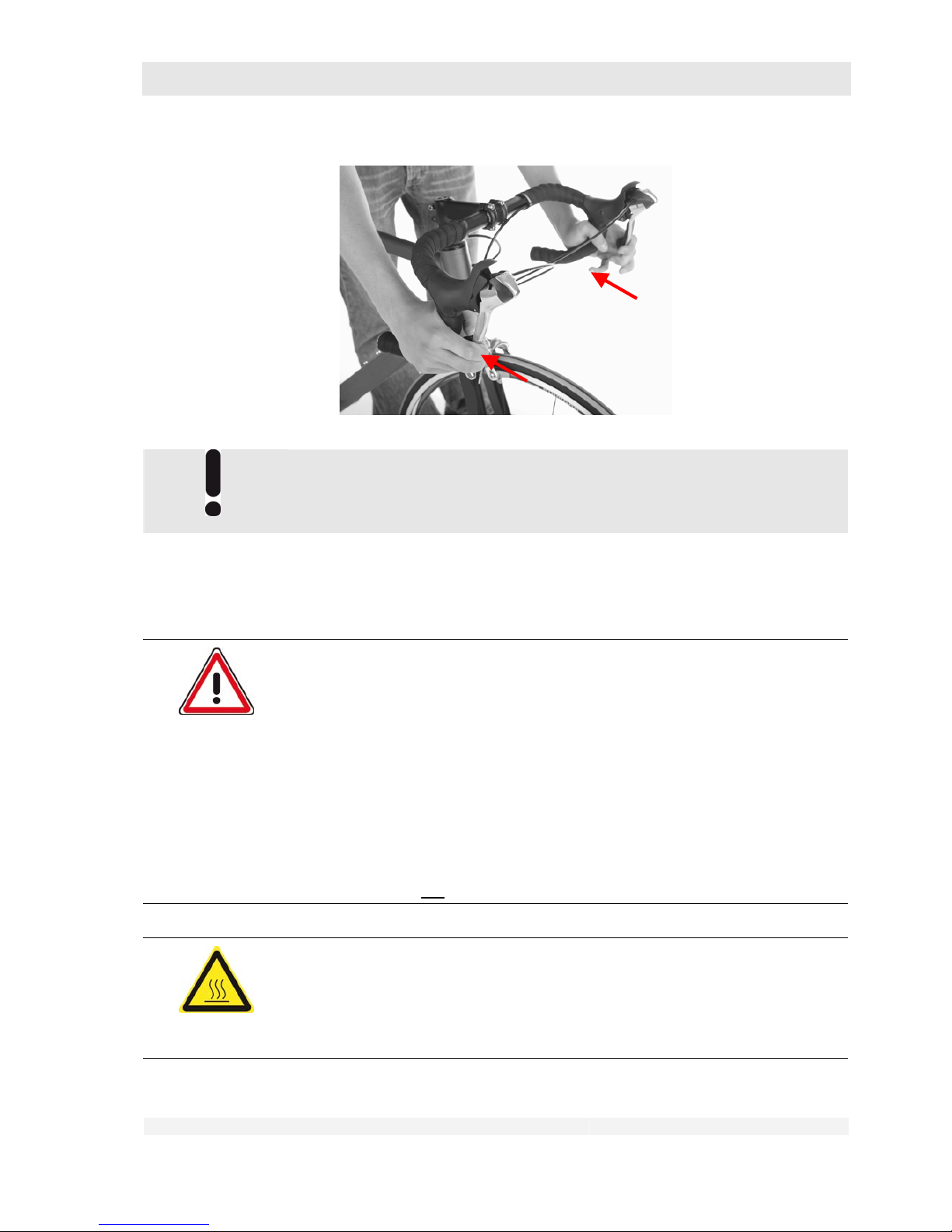
GHOST
User Manual Status 04/2009 // Spec 2010
7.72
The best braking effect is achieved by correctly dosing the actuation of both
brake levers at the same time.
7.8 Operating the quick-release hub axle
Danger of personal injury and material damage!
Incorrect installation of the wheels using the quick-release hub axle can lead to
dangerous riding situations, falls, accidents and material damage.
Observe the following description for operation of the quick-release hub
axle
Familiarise yourself with the use of the quick-release hub axle
Practice the installation and removal of the wheels with the quick-
release hub axle several times
Inspect the wheels as described in chapter 6.1.1 after every installation
If you are not sure about the correct fitting after installation of the
wheels, do not
use the bike and contact your dealer.
Risk of burns!
The quick-release levers on disc brakes can become hot while riding.
Touch the quick-release lever briefly with your bare finger.
If it feels hot, allow it to cool down.
Page 73
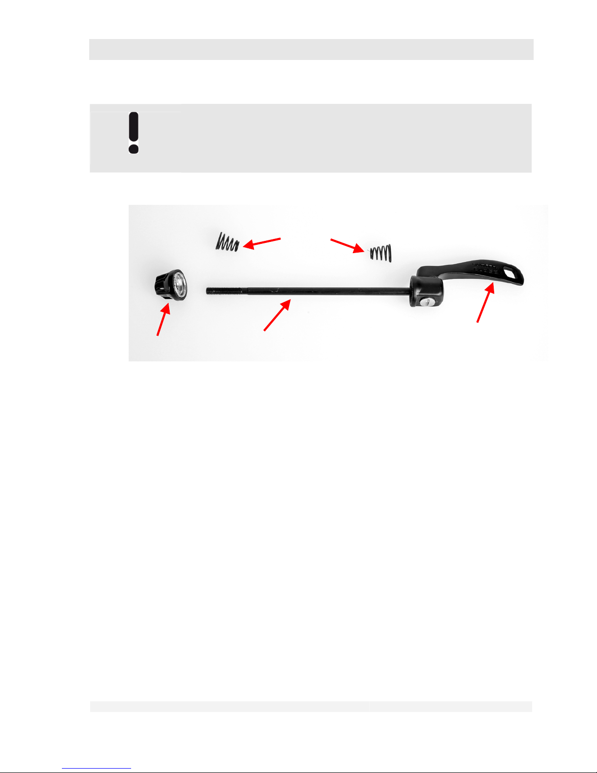
GHOST
User Manual Status 04/2009 // Spec 2010
7.73
Special forms:
Some wheels are attached with slide-in shafts or with a combination of slide-in
shaft and quick-release lever. For details of their use, please refer to the user
manual from the component manufacturer supplied with the bike.
Legend:
1: Axle
2: Screw nut
3: Lever
4: Spring
The hubs of your wheels and possibly also the clamp of your saddle post are fitted with quickrelease axles (often also referred to as “quick-release levers”).
These quick-release axles permit quick removal and installation of these components without the
use of tools. This is effected by means of a
– Long axle with thread, on the one end fitted with a
– screw nut, at the other end an
– eccentrically pivoted lever.
– There is a small spring between the screw nut and the hub, and between the lever and the
hub.
– The ends of the springs with the smaller diameter face towards the hub in each case.
– On quick-release levers for saddle post clamping, the axle end may have a bolt head with
hexagonal socket instead of the nut.
Opening the quick-release axle:
1. Press the eccentrically pivoted lever away from the hub. It can now be turned by
approx. 180° about its own axis.
1
2
4
3
Page 74
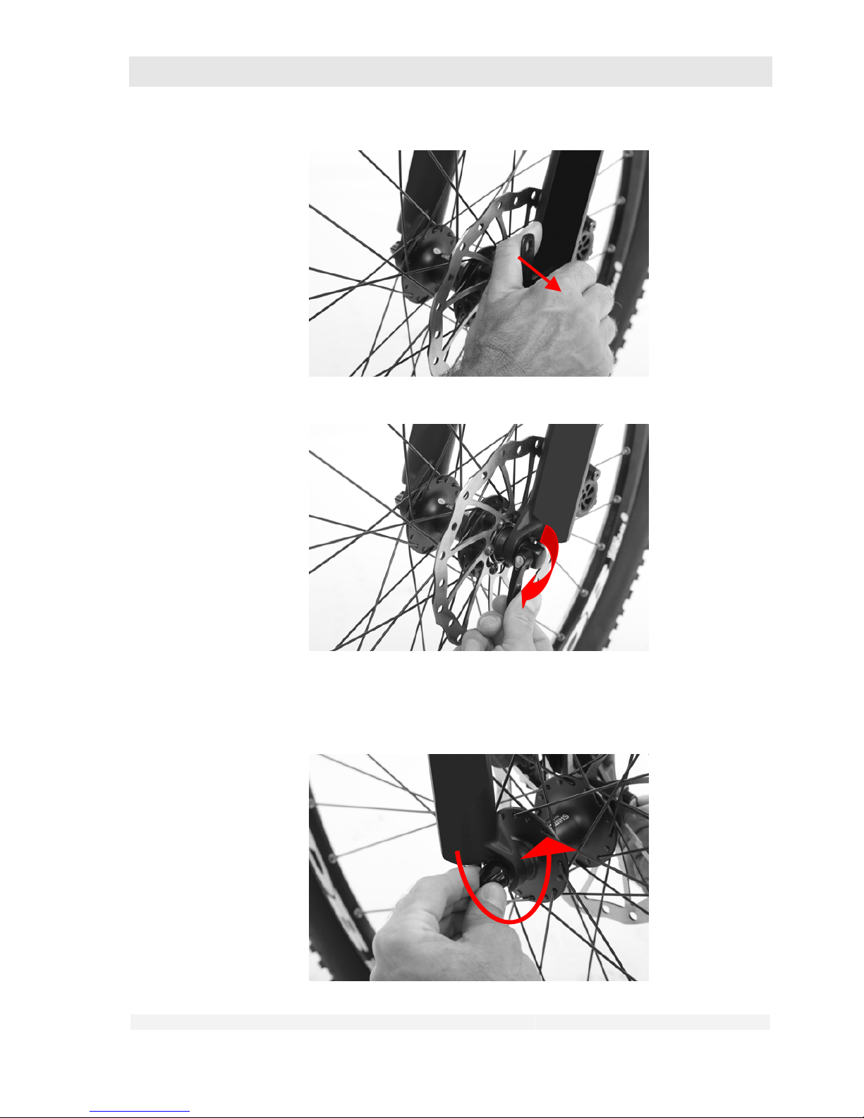
GHOST
User Manual Status 04/2009 // Spec 2010
7.74
2. Turn the screw nut in anti-clockwise direction until the wheel can be pulled out
of the frame or front forks without great effort. Should the nuts come off the
screw completely, ensure that the small springs are not lost.
Page 75
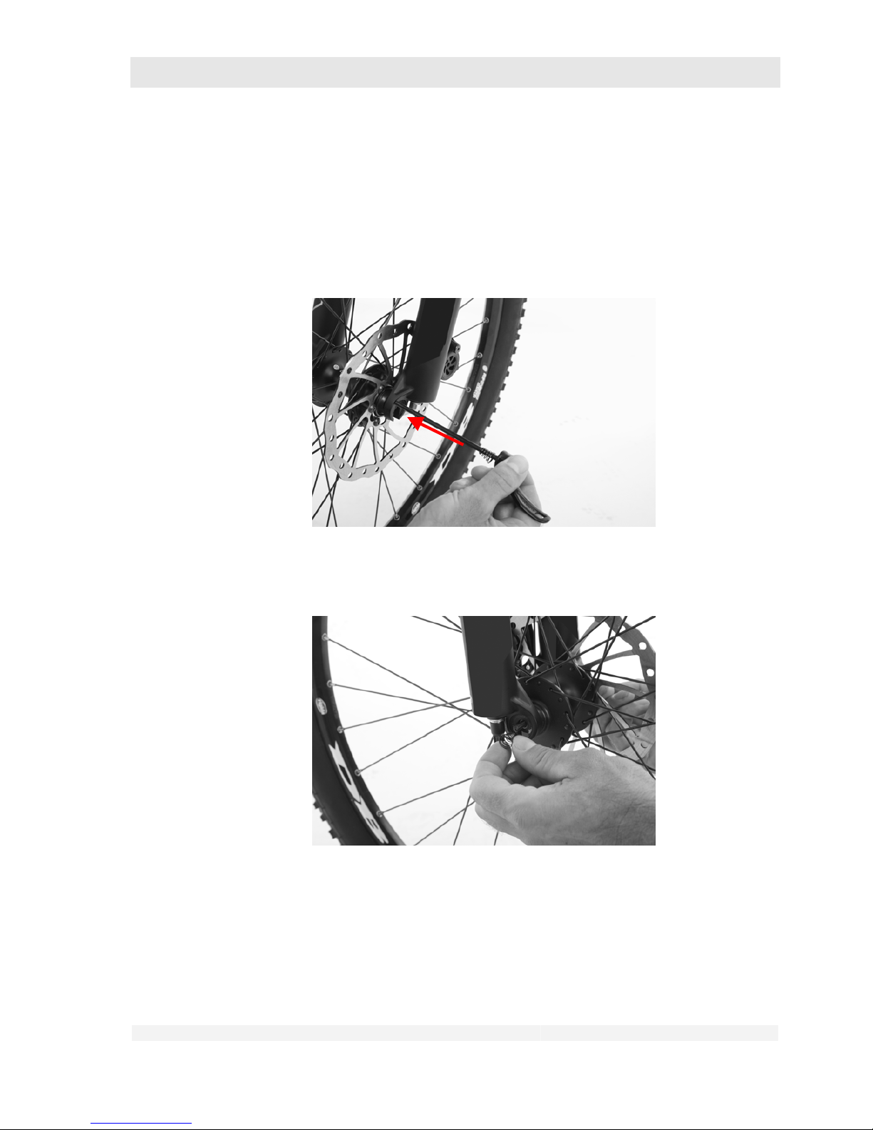
GHOST
User Manual Status 04/2009 // Spec 2010
7.75
3. In the case of quick-release levers for saddle post clamping: Turn the bolt at the
hexagonal socket (instead of the nut) in anti-clockwise direction to release the
saddle post.
Closing: In the reverse sequence
1. If the quick-release axle was completely removed from the hub, push it through
the hub from the left-hand side (as seen in riding direction).
2. Place the spring and screw nut onto the axle. Now screw the screw nut on to
the right-hand end now protruding out of the hub in clockwise direction.
Page 76
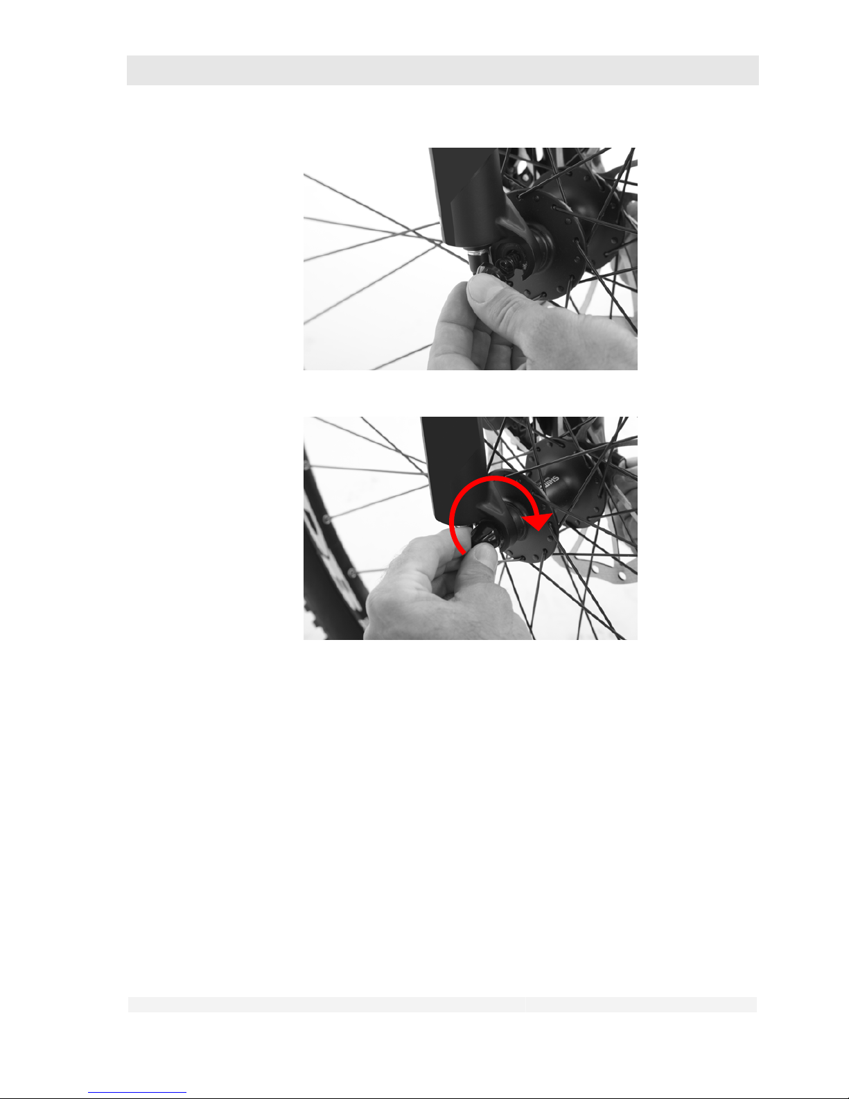
GHOST
User Manual Status 04/2009 // Spec 2010
7.76
3. In the case of quick-release levers for saddle post clamping: Turn the bolt at the
hexagonal socket (instead of the nut) in clockwise direction to secure the saddle
post.
4. Tilt the eccentrically pivoted lever so that it forms roughly the extension of the
hub axle. Hold the lever in this position.
Page 77
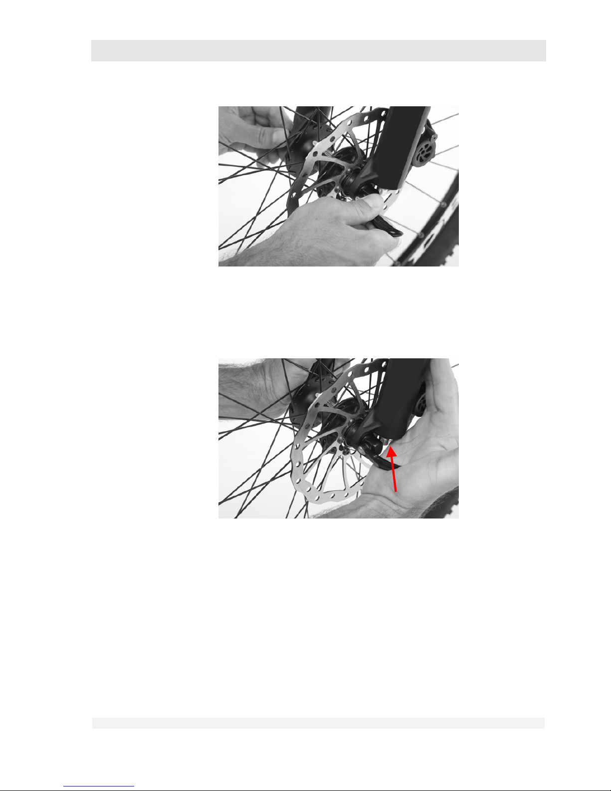
GHOST
User Manual Status 04/2009 // Spec 2010
7.77
5. Now turn the screw nut of the hexagon socket until the eccentrically pivoted
lever when turned by 90° about its pivot can only move against a resistance (it
then forms more or less the straight extension of the hub axle).
6. Now press the lever by a further 90° up to its end position.
Page 78
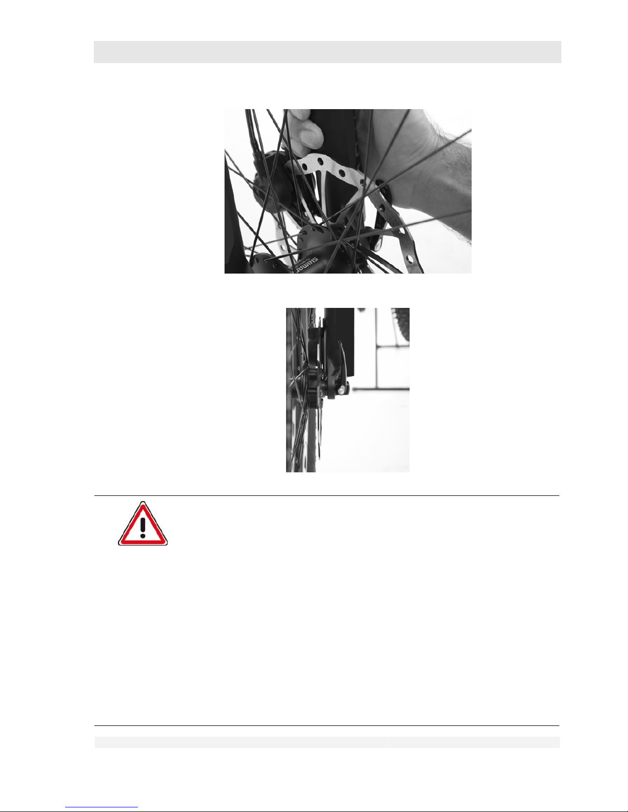
GHOST
User Manual Status 04/2009 // Spec 2010
7.78
Danger of personal injury and material damage!
Incorrect use of the brakes can lead to dangerous riding situations, falls,
accidents and material damage.
If the lever can be pushed too easily into its end position, the wheel is not
clamped tightly enough and may slip or come loose while riding.
Risk of accidents!
Open the lever again and turn the screw nut correspondingly further in
clockwise direction.
If the lever can only be moved into its end position (= 90° to the hub axle) with
very great force or not at all, on no account leave the lever in this position.
It may come loose during riding due to the eccentric pivot.
Acute risk of accidents!
Open the lever again and turn the screw nut correspondingly back in
anti-clockwise direction.
Check that the wheels are securely fitted as described in chapter 6.1.1.
Page 79
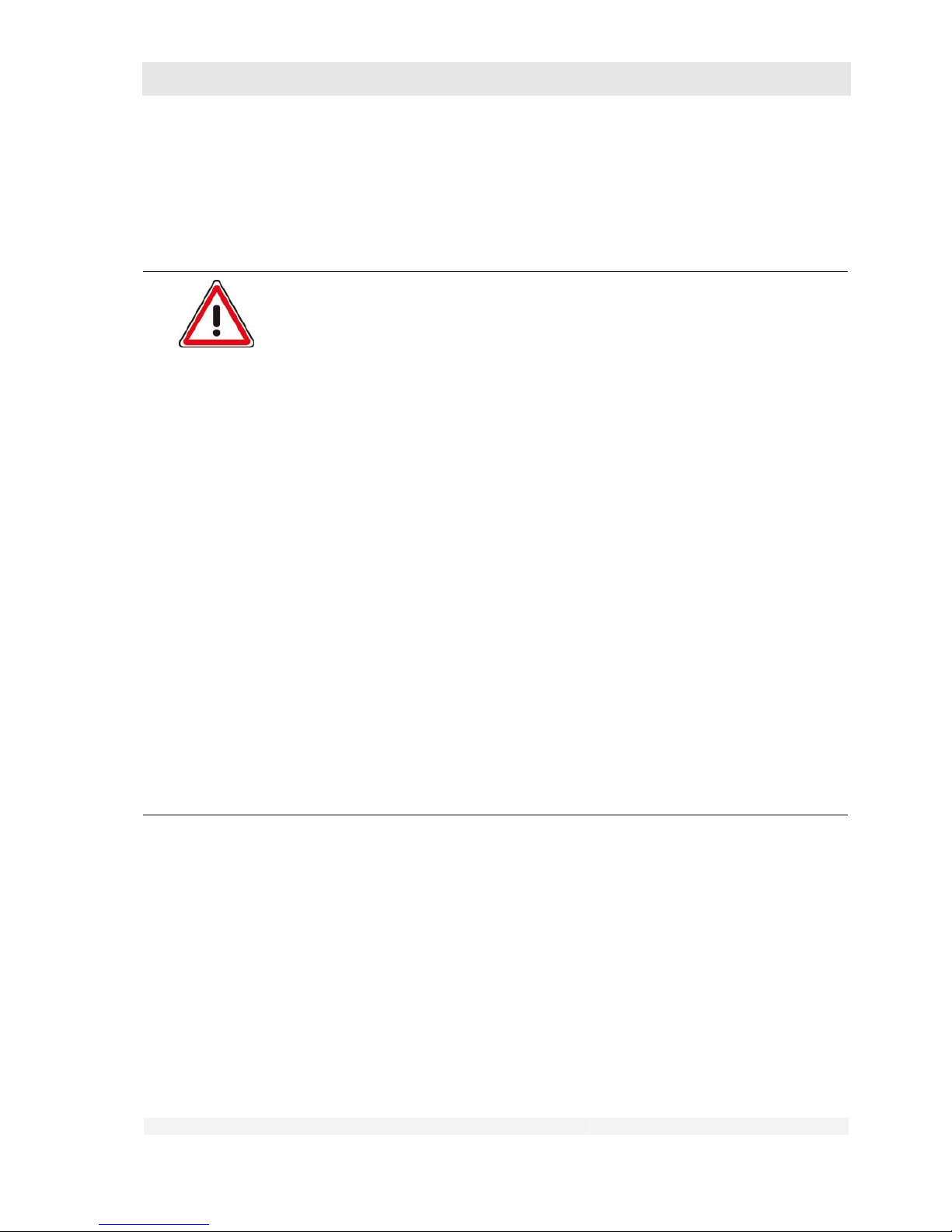
GHOST
User Manual Status 04/2009 // Spec 2010
7.79
7.9 Use of clipless pedals
Danger of personal injury and material damage!
Clipless pedals are not safety pedals.
If the release force is set too high, you may not be able to twist the shoes out of
the pedals quickly enough in an emergency situation.
If the release force is set too low, the shoe may come off the pedal
unintentionally while riding.
In both cases there is an increased risk of accidents and injury.
Familiarise yourself with the use of the clipless pedals.
Practice getting on and off the bike with the pedals several times at
standstill. Sit on the saddle and steady yourself by holding on to a
suitable, stable object. Clip the two shoes alternately in and out. Please
consult your dealer if you have any questions.
Familiarise yourself with the release mechanism by careful practice
rides.
Find the optimum release force for yourself.
Practice getting on and off the bike with different release force settings.
For details of adjusting the release force, please consult the component
user manual supplied with the bike and/or contact your dealer.
In unclear traffic situations and in difficult terrain it is often necessary to unclip
one or even both shoes
Practice this alternately on both sides.
Place your shoe on the middle of the pedal when pedalling without
clipping in.
If necessary you can then support yourself with one or both legs on the
ground.
Page 80
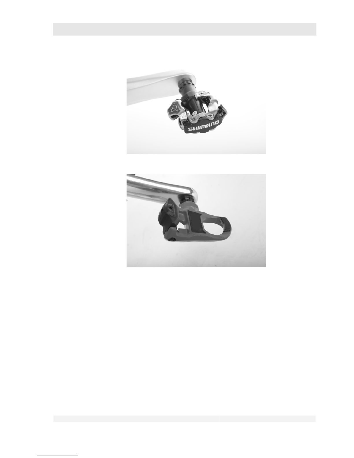
GHOST
User Manual Status 04/2009 // Spec 2010
7.80
With clipless pedals, shoe and pedal are firmly linked in vertical direction. You can therefore not
only press the pedal down when riding, but also pull it up. In order to be able to use a clipless pedal
you need the appropriate shoes for the pedal system in use that are fixed to the pedal clip supplied
with the pedal.
Page 81
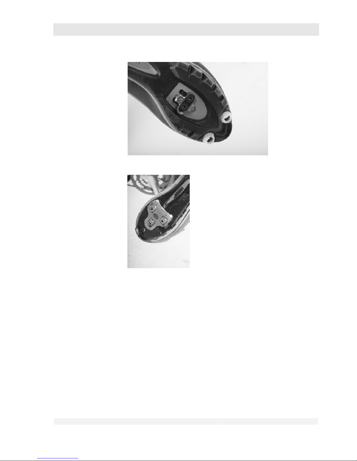
GHOST
User Manual Status 04/2009 // Spec 2010
7.81
1. Have this installation carried out by your dealer.
2. Getting on to the pedal:
a) Move the pedal to its lowest position.
b) Position the hook tip on the shoe in the front recess of the pedal with the tip of
the shoe facing downwards.
Page 82
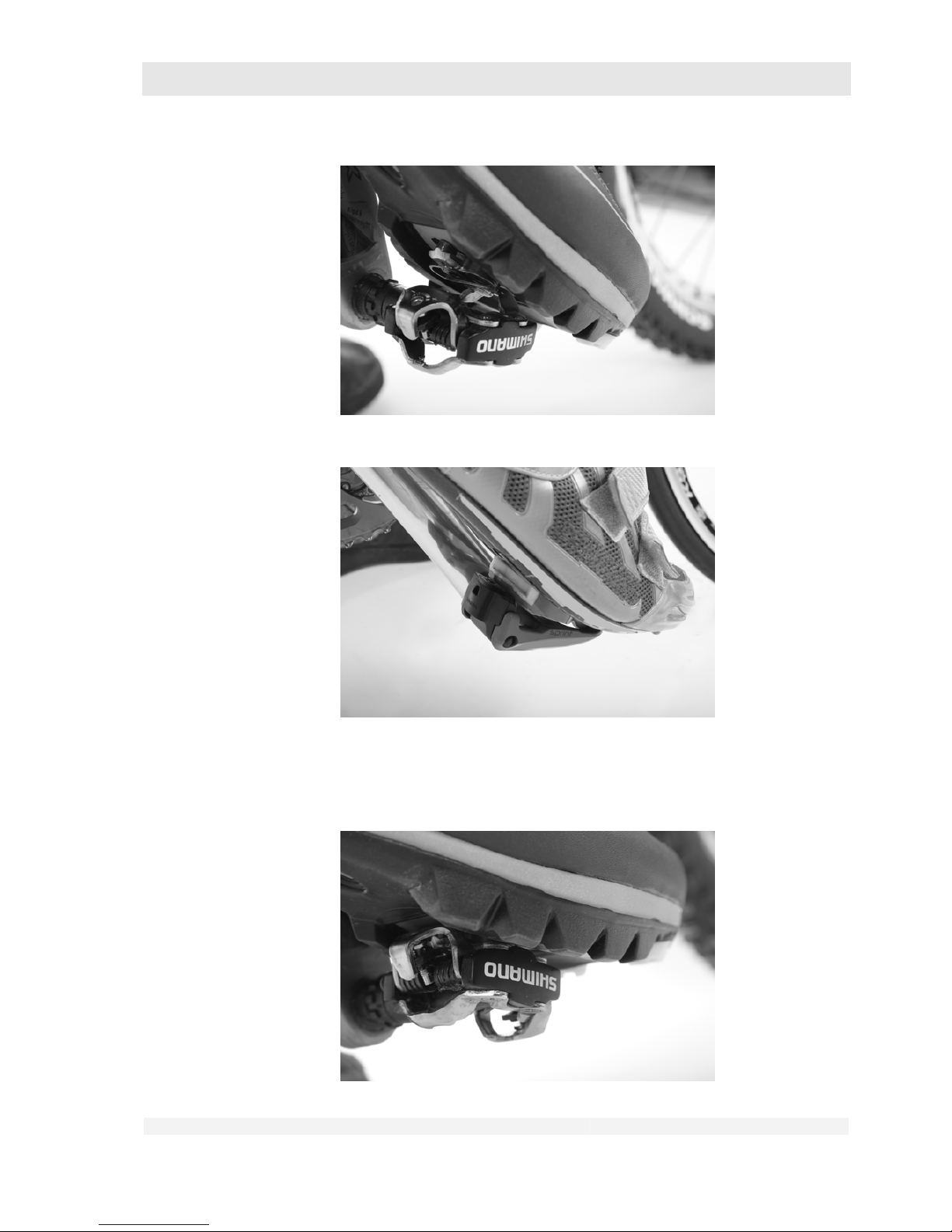
GHOST
User Manual Status 04/2009 // Spec 2010
7.82
c) When the hook tip is in the right position in the pedal,
press down firmly with the whole of your foot until the clamping mechanism
engages quite audibly.
Page 83
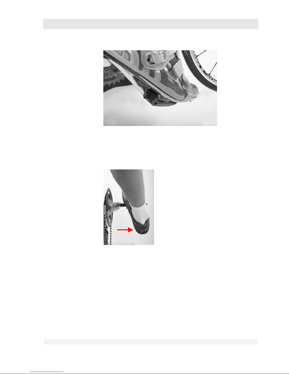
GHOST
User Manual Status 04/2009 // Spec 2010
7.83
The shoe is now firmly linked to the pedal in vertical direction. Depending on the
pedal system, the shoe may have some lateral freedom of movement.
3. Releasing your shoe from the pedal:
Twist your heel with a powerful jerk away from the bike.
Page 84
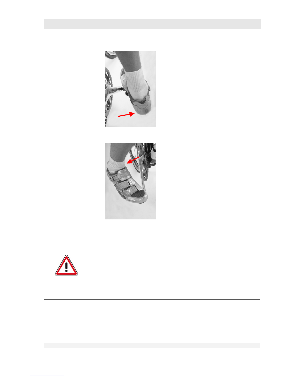
GHOST
User Manual Status 04/2009 // Spec 2010
7.84
7.10 Loading the luggage rack
Danger of personal injury and material damage!
A luggage rack is not intended for the transport of bulky goods or persons.
Misuse can lead to dangerous riding situations, falls, accidents and material
damage.
Transport only compact luggage items with a max. weight of 25 kg using
suit-able restraint systems.
Your luggage rack is intended for the transport of compact luggage items and as the mounting for
panniers.
• Place your luggage on the middle of the luggage rack.
Page 85

GHOST
User Manual Status 04/2009 // Spec 2010
7.85
• If you use panniers, ensure that they are suitable for attachment to your
luggage rack. Install them according to the user manual. Consult the
corresponding user manual and/or contact your dealer.
• Secure your luggage with the spring clip or special luggage straps.
• “Shake” your bike back and forth after loading.
• The luggage or panniers must not come loose.
• Your luggage or panniers must not hinder your freedom of movement when
riding.
• Your luggage or panniers must not touch the wheels.
• Your luggage or panniers must not cover the lights or reflectors of the bike.
Page 86
GHOST
User Manual Status 04/2009 // Spec 2010
8.86
8 Faults When Riding
Danger of personal injury and material damage!
If you carry out maintenance measures for which you are not authorised, this
can lead to dangerous riding situations, falls, accidents and material damage.
Have maintenance measures not listed in the following table carried out only by
your dealer.
Danger of personal injury and material damage!
If you discover unusual handling behaviour, unusual noises or faults that are
not described in this chapter, this can lead to dangerous riding situations, falls,
accidents and material damage.
Have any problems not described in the following table checked and, where
necessary, remedied by your dealer without delay.
8.1 Gear shift, drive
Problem Possible causes Remedy
Shift lever not actuated correctly Actuate the lever again
Shift mechanism maladjusted Have adjusted in an approved
workshop
Gears do not change or do not
change smoothly
On steep incline, too much
pressure on the pedal and/or
pedal motion too slow
Repeat shifting procedure in flat
land
Shift at standstill: Raise the rear
wheel, turn the crank in drive
direction until the desired gear is
engaged.
Drive blocks during or after gear
shifting
Chain jamming
Stop, actuate the switch in the
opposite direction, raise the rear
wheel, turn the crank against the
drive direction.
If the crank cannot be turned, on
no account exert great force.
Contact an approved workshop
immediately.
Unusual noise such as cracking,
loud grinding and/or banging
Drive/gearing components
damaged
Contact an approved workshop
immediately.
Page 87
GHOST
User Manual Status 04/2009 // Spec 2010
8.87
Problem Possible causes Remedy
Irregular resistance during the
pedal movements
Drive/gearing components
damaged
Contact an approved workshop
immediately.
Chain jumped off sprocket
Wrong actuation of the gear shift
(see chapter 7.7)
Maladjusted or damaged gear
shift mechanism
fundamentally possible under
unfavourable conditions
Stop riding,
lift the chain onto the next
sprocket by hand,
raise the rear wheel,
turn the crank in drive direction
(only if it turns easily).
If a repair is not possible in this
way, contact an approved
workshop immediately.
Chain jumped off during or after
gear shifting
Wrong actuation of the gear shift
(see chapter 7.7)
Maladjusted or damaged gear
shift mechanism
fundamentally possible under
unfavourable conditions
Stop riding,
actuate the gear shift in the
opposite direction,
lift the chain onto the next
sprocket by hand,
raise the rear wheel,
turn the crank in drive direction
(only if it turns easily).
If a repair is not possible in this
way, contact an approved
workshop immediately.
Chain jumps off continuously
Constant wrong actuation of the
gear shift mechanism
Maladjusted or damaged gear
shift mechanism
Operate the gear shift
mechanism only as described in
chapter 7.7.
If the chain jumps off despite
correct actuation of the gear shift
mechanism, contact an
approved workshop
immediately.
8.2 Brakes
Danger of personal injury and material damage!
The brakes on your bike are among the most important components for your
riding safety.
Incorrectly functioning brakes can lead to dangerous riding situations, falls,
accidents and material damage.
Contact your dealer immediately in the event of even the slightest
malfunction or decreasing braking effect.
Ride your bike again only when it has been properly repaired by your
dealer.
Page 88
GHOST
User Manual Status 04/2009 // Spec 2010
8.88
Problem Possible causes Remedy
Brakes not correctly installed
Install correctly as described in
chapter 10.1
Brakes do not work
Brakes damaged Contact an approved workshop
immediately.
Brake blocks or brake pads worn Have the brake blocks or brake
pads replaced immediately in an
approved workshop.
Brake cables stretched, worn or
clamp damaged
Contact an approved workshop
immediately.
Decreasing braking effect, brake
levers can be pulled too far
With hydraulic brakes: Brake
system leaking
Contact an approved workshop
immediately.
8.3 Frame and suspension
Danger of personal injury and material damage!
Faults in the frame and suspension can lead to dangerous riding situations,
falls, accidents and material damage.
Contact your dealer immediately in the event of even the slightest
malfunction.
Ride your bike again only when it has been properly repaired by your
dealer.
Problem Possible causes Remedy
Noises: Cracking, banging,
grinding, etc.
Frame and/or suspension
damaged
Contact an approved workshop
immediately.
Improper suspension function Suspension not correctly
adjusted
Adjust correctly according to the
component user manual supplied
with the bike.
Improper suspension function
despite correct adjustment
Suspension damaged Contact an approved workshop
immediately.
Page 89
GHOST
User Manual Status 04/2009 // Spec 2010
8.89
8.4 Mudguards, luggage rack, lights
Danger of personal injury and material damage!
Faults in the mudguards, luggage rack and lights can lead to dangerous riding
situations, falls, accidents and material damage.
Contact your dealer immediately in the event of even the slightest
malfunction.
Ride your bike again only when it has been properly repaired by your
dealer.
Problem Possible causes Remedy
Noises: Cracking, banging,
grinding, etc.
Mudguard or luggage rack parts
loose
Contact an approved workshop
immediately.
Bulb(s) blown Replace the bulb(s) Please
consult your dealer.
Cables damaged
Lights partially or completely
without function
Dynamo defective
Contact an approved workshop
immediately.
8.5 Wheels and tyres
Danger of personal injury and material damage!
Faults in the wheels and tyres can lead to dangerous riding situations, falls,
accidents and material damage.
Contact your dealer immediately in the event of even the slightest
malfunction.
Ride your bike again only when it has been properly repaired by your
dealer.
Problem Possible causes Remedy
Wheels “jump”
Tyre damaged
Spoke broken
Contact an approved workshop
immediately.
Noises: Cracking, banging,
grinding, etc.
Foreign matter has become
trapped in the wheel
Remove the foreign matter. Use
your bike very carefully after
that.
Have your bike checked in an
approved workshop for possible
consequential damage.
Page 90

GHOST
User Manual Status 04/2009 // Spec 2010
8.90
Problem Possible causes Remedy
Damage to the wheel Contact an approved workshop
immediately.
“Spongy” riding behaviour Tyre pressure too low Increase the tyre pressure (see
chapter 6.1.3). If the same riding
behaviour occurs again fairly
shortly thereafter, the tyre has a
slow puncture (see next line).
Increasingly “spongy” riding
behaviour
Very unusual wheel rolling
behaviour (you feel every small
stone)
Flat tyre
Replace inner tube, possibly
also tyre and rim tape;
in the case of tubeless tyres:
Replace the tyre.
Contact an approved
workshop(*) immediately. The
bike must not be used until then.
(*): You can replace inner tube,
tyre and rim tape yourself if you
have sufficient experience. Have
your dealer show you how to do
this and practice this work until
you are familiar with it. For
removal and installation of the
wheels, see chapters 7.9 and
10.2.
Page 91
GHOST
User Manual Status 04/2009 // Spec 2010
9.91
9 After an Accident or Fall
Danger of personal injury and material damage!
Damage after an accident or fall can lead to dangerous riding situations, falls,
accidents and material damage.
Contact your dealer immediately after an accident or fall.
Ride your bike again only when it has been properly repaired by your
dealer.
After a fall you must always have all damaged bike parts such as
• Handlebars
• Bar ends
• Handlebar stem
• and crank
replaced.
All other parts of the bike must be inspected by your dealer and replaced, if necessary.
Danger of personal injury and material damage!
More and more bikes are being equipped with carbon components.
Carbon components are very delicate and can lead to dangerous riding
situations, falls, accidents and material damage if incorrectly installed or after
slight damage.
Observe all the special instructions on installation, care, maintenance
and inspection of these parts in the components user manuals supplied
with the bike.
Have installation work of or on carbon parts carried out only in an
approved workshop.
After damage or falls, always contact your dealer.
Use your bike again only when he has replaced the damaged parts or
has assured you that the bike is safe to use.
Page 92
GHOST
User Manual Status 04/2009 // Spec 2010
10.92
10 Transporting the Bike
Danger of personal injury and material damage!
An unsuitable transport system can cause damage to safety-relevant parts of
the bike and lead to dangerous riding situations, falls, accidents and material
damage.
Transport this bike only inside your car.
This bike may only be transported inside motor vehicles. Ensure that the bike is secured for
transport and is not damaged e.g. by other luggage items.
Front and rear wheel and the saddle post with saddle may be removed for transport if they are
fitted with quick-release axles. Remove these parts only if you are sure that you can install them
again correctly. See chapter 7.9.
If your wheels are bolted to the frame (e.g. with hub gears), please contact your dealer.
Danger of material damage!
If your bike is transported inside the motor vehicle, exposure to direct sunlight
may cause the tyres to burst or come off the wheel rim.
Let the air out of the tyres before transport and inflate them again after
transport (see chapter 6.1.3.).
10.1 Removing and installing wheels
Danger of personal injury and material damage!
Incorrectly installed wheels can lead to dangerous riding situations, falls,
accidents and material damage.
Have your dealer show you how to correctly remove and install the
wheels.
Practice these operations at least once under his supervision and
control.
Carry out removal and installation only when you are sure that you can
do this correctly.
Page 93
GHOST
User Manual Status 04/2009 // Spec 2010
10.93
Danger of material damage!
Hydraulic brakes must never be actuated after removal of the wheel!
Should your bike have disc brakes, please use the prescribed transport locking
devices provided for transport after removal of the wheel.
Remove these only immediately before installing the wheel again.
Observe the component user manual provided.
Danger of personal injury and material damage!
Bikes with rim brakes only:
The brake blocks may be twisted by the tyres during removal and installation of
the wheels.
Pay attention to the correct position of the brake blocks after installation
of the wheels (see chapter 6.8).
If they are not in the correct position, contact an approved workshop
immediately.
You may remove the wheels from your bike for transport and install them again after transport if
they are fitted with quick-release axles.
If your bike has rim brakes, pay attention that the position of the brake blocks
is not changed by the tyres. This could easily happen with large-volume tyres.
If the tyre does not fit easily between the brake blocks, release a
corresponding amount of air. Inflate the tyres again after installation to the
correct tyre pressure.
10.1.1 All categories except RACE Series
First remove the front wheel:
1. Release the rim brake.
a) On rim brakes with cable (e.g. from Shimano):
• Press the brake pads together with one hand and unhook the cable guide
from the bracket with the other.
Page 94
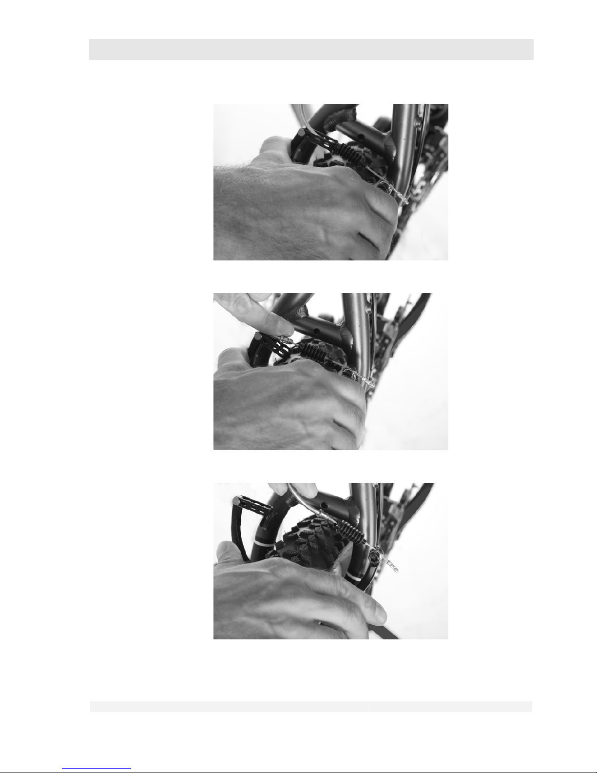
GHOST
User Manual Status 04/2009 // Spec 2010
10.94
Page 95
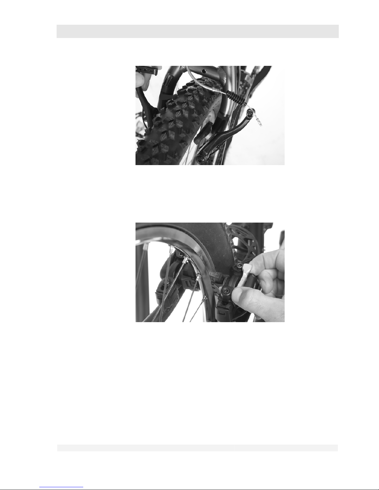
GHOST
User Manual Status 04/2009 // Spec 2010
10.95
b) With Magura hydraulic rim brakes:
• Fold over the mounting lever and pull the whole brake with brake booster
from the brake holders.
• Ensure that any loose spacer washers are not lost.
Page 96
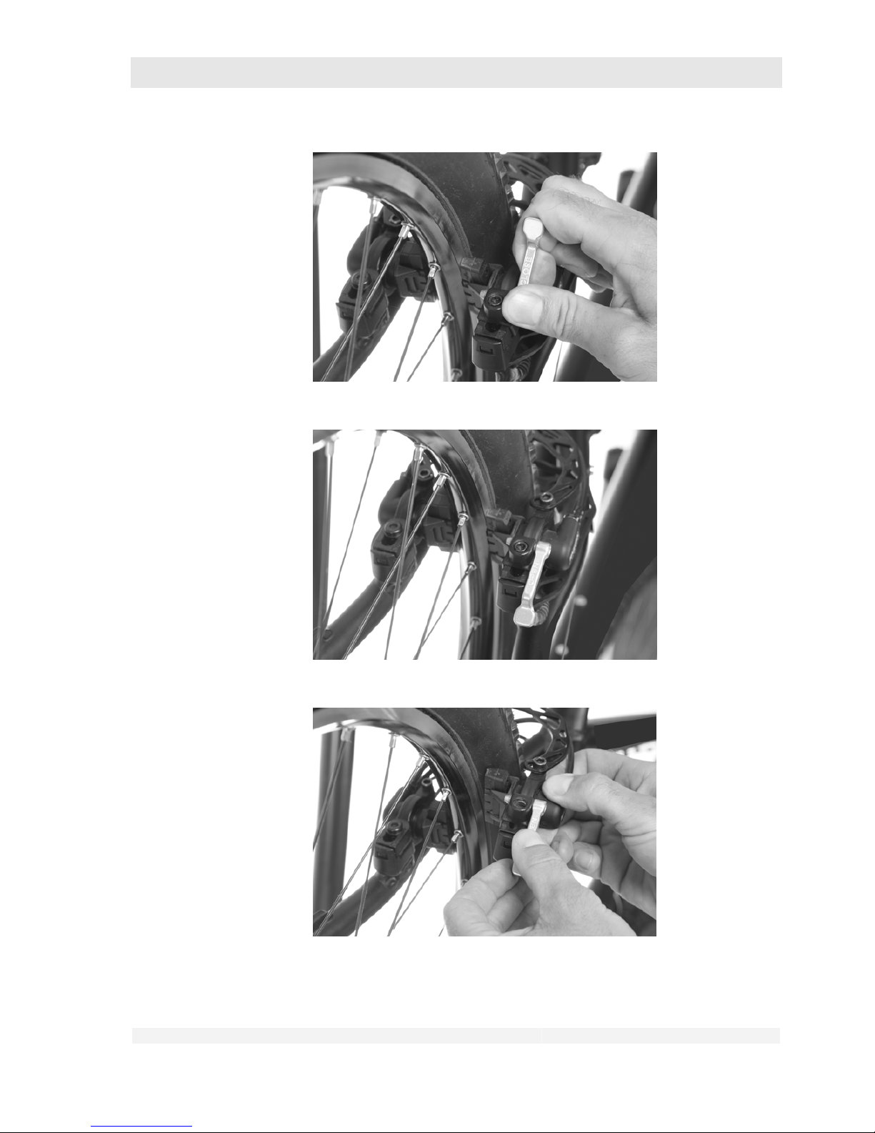
GHOST
User Manual Status 04/2009 // Spec 2010
10.96
Page 97
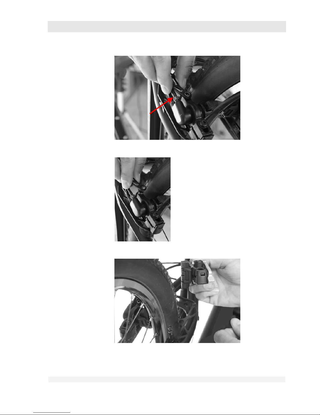
GHOST
User Manual Status 04/2009 // Spec 2010
10.97
2. Shift to the smallest pinion of the sprocket assembly on the rear wheel (see
chapter 7.7).
Page 98
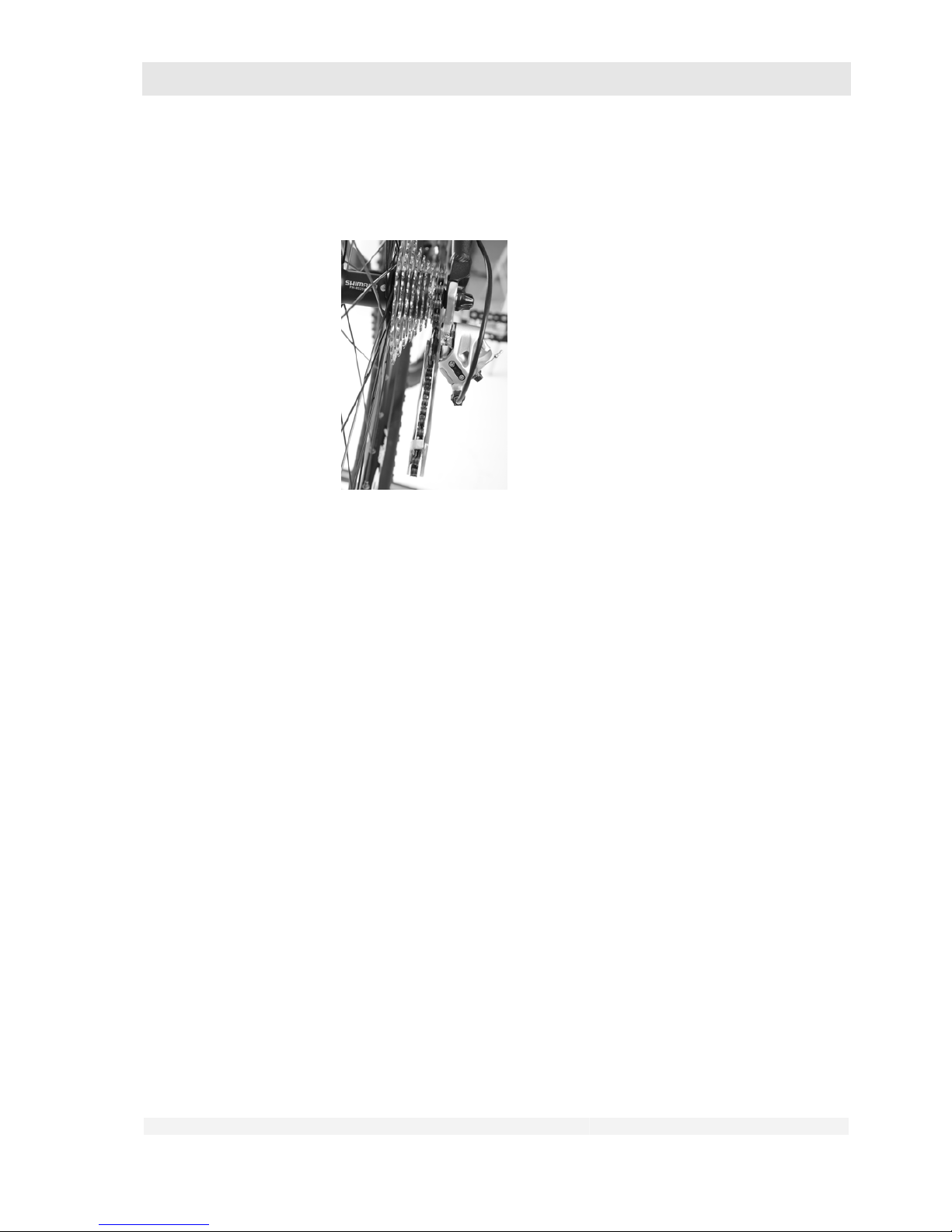
GHOST
User Manual Status 04/2009 // Spec 2010
10.98
• To do this, raise the bike at the rear, actuate the corresponding switch and
turn the crank in drive direction by hand until the chain is engaged on the
smallest pinion.
3. On the front wheel with hub dynamo (if installed):
• Disconnect the plug connector between dynamo and wiring.
4. Loosen the wheel hubs.
• Open the quick-release lever on your wheel (see also chapter 7.9 “Quick-
release levers”).
• Back off the lock nut until it is just still on the axle.
With other clamping systems:
• Loosen the clamping system as described in the component user manual
supplied.
5. Remove the wheels from frame and forks.
• Front wheel: Pick up the bike with the handlebars and pull the wheel out of
the fork ends of the front-wheel forks.
• Rear wheel: Raise the bike at the rear end and push the gear shift
mechanism to the rear. In this position, push the rear wheel with alight
pressure towards the opening in the frame.
Page 99

GHOST
User Manual Status 04/2009 // Spec 2010
10.99
6. After removing the wheels, lay the bike carefully on its left side.
Page 100
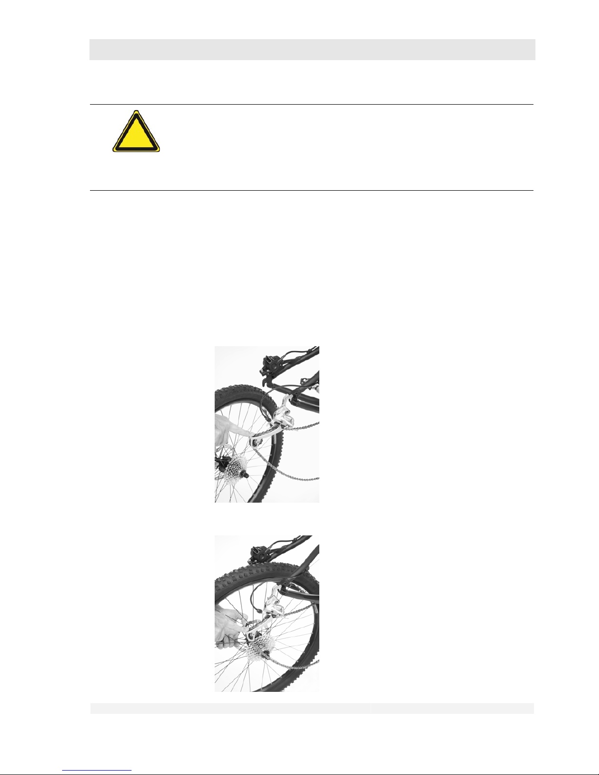
GHOST
User Manual Status 04/2009 // Spec 2010
10.100
Danger of material damage!
When the rear wheel has been removed, the frame and/or gear shift mechanism
may be damaged.
After removing the rear wheel, lay the bike on its left side or use a suitable
assembly stand.
Installing the wheels.
First install the rear wheel.
1. a) Insert the rear wheel:
• Raise the bike at the rear,
• place the rear wheel under the frame so that the chain fits over the smallest
pinion.
• With disc brakes: Insert the wheel so that the brake disc slides smoothly
between the brake pads.
 Loading...