

Valid from firmware-version 7.02
As of 2017-02-06
ProfiLux 4
Programming Guide

ProfiLux 4 Programming Guide
Table of Contents
PREFACE .................................................................................................................................................................... 6
GET THE MOST OUT OF YOUR GHL PRODUCT .......................................................................................................................... 6
ABOUT THIS PROGRAMMING GUIDE ....................................................................................................................................... 6
SAFETY INSTRUCTIONS ......................................................................................................................................................... 7
INTENDED USE ................................................................................................................................................................... 7
1 FUNCTIONALITY AND OPERATING CONCEPT ..................................................................................................... 7
1.1 FUNCTIONALITY OF THE P4 ....................................................................................................................................... 7
1.2 OPERATING CONCEPT ........................................................................................................................................... 10
1.3 EXAMPLES OF SETTINGS ......................................................................................................................................... 10
1.3.1 How to setup Temperature control ......................................................................................................... 10
1.3.2 How to set the Illumination? ................................................................................................................... 10
1.3.3 How to set the Level control? .................................................................................................................. 11
1.3.4 How to set the Current pump control? .................................................................................................... 11
1.3.5 How to set Dosing or Timer activities? .................................................................................................... 11
1.4 FEATURES / RESOURCES ........................................................................................................................................ 11
1.5 NUMBERING AND DISPLAY OF RESOURCES ................................................................................................................ 11
2 CLOCK .............................................................................................................................................................. 12
2.1 TIME & DATE, DCF .............................................................................................................................................. 12
2.2 REMINDERS ......................................................................................................................................................... 13
2.3 TIMERS .............................................................................................................................................................. 14
2.4 DOSING PUMP ..................................................................................................................................................... 17
2.5 LOCATION ........................................................................................................................................................... 19
3 ILLUMINATION ................................................................................................................................................ 19
3.1 ILLUMINATION RUN .............................................................................................................................................. 20
3.2 COPY AN ILLUMINATION RUN USING GCC ................................................................................................................. 21
3.3 TIME SHIFT WITH GGC .......................................................................................................................................... 21
3.3.1 Time shift during clouds .......................................................................................................................... 21
3.3.2 Time shift for Illumination Run ................................................................................................................ 22
3.4 MANUAL ILLUMINATION ........................................................................................................................................ 23
3.5 CLOUDS .............................................................................................................................................................. 24
3.6 MOON ............................................................................................................................................................... 24
3.7 RAINY DAYS ........................................................................................................................................................ 25
3.8 BURNING-IN ........................................................................................................................................................ 25
3.9 OPERATING HOURS ............................................................................................................................................... 26
3.10 THUNDERSTORMS ................................................................................................................................................ 26
3.11 TEMPERATURE-DEPENDENT LIGHT REDUCTION ........................................................................................................... 27
3.12 VARIABLE ILLUMINATION ....................................................................................................................................... 29
3.13 MITRAS LIGHTBAR ................................................................................................................................................ 29
3.14 LIGHT DEMO ........................................................................................................................................................ 29
3.15 TIME LAPSE ......................................................................................................................................................... 30
3.16 ACCLIMATION ...................................................................................................................................................... 30
3.17 SHIFT CURVES ...................................................................................................................................................... 31
4 EXTRAS ............................................................................................................................................................ 31
4.1 MAINTENANCE .................................................................................................................................................... 31
4.2 FEEDING PAUSE ................................................................................................................................................... 33
4.3 INTERNAL TIME .................................................................................................................................................... 34
4.4 INFO & SUPPORT ................................................................................................................................................. 34
4.5 CURRENT ............................................................................................................................................................ 34
EN 2017-02-06 2

ProfiLux 4 Programming Guide
4.5.1 Nocturnal Change .................................................................................................................................... 35
4.5.2 Group Settings ......................................................................................................................................... 35
4.5.3 Pump Settings .......................................................................................................................................... 39
4.6 EHEIM ................................................................................................................................................................ 39
4.7 DISPLAY .............................................................................................................................................................. 40
4.8 MEASUREMENT DATA ........................................................................................................................................... 40
4.9 LANGUAGE .......................................................................................................................................................... 42
5 SENSOR SETTINGS ........................................................................................................................................... 42
5.1 ACTIVITY ............................................................................................................................................................. 43
5.2 NOMINAL VALUE.................................................................................................................................................. 43
5.3 OPERATION HOURS .............................................................................................................................................. 45
5.4 HYSTERESIS ......................................................................................................................................................... 45
5.5 ALARM ............................................................................................................................................................... 46
5.6 NOCTURNAL CHANGE............................................................................................................................................ 48
5.7 SUMMER SWITCHING ............................................................................................................................................ 49
5.8 THERAPY ............................................................................................................................................................ 50
5.9 CALIBRATION ....................................................................................................................................................... 50
5.9.1 General .................................................................................................................................................... 51
5.9.2 Calibration Tolerance .............................................................................................................................. 51
5.9.3 Overview of the Calibration values .......................................................................................................... 52
5.9.4 Temperature Sensor (Analog).................................................................................................................. 52
5.9.5 pH Sensor ................................................................................................................................................. 53
5.9.6 Redox-Sensor ........................................................................................................................................... 53
5.9.7 Conductivity ............................................................................................................................................. 54
5.9.8 Oxygen Sensor ......................................................................................................................................... 55
5.9.9 Control of Sensor calibration ................................................................................................................... 56
5.10 DISPLAY .............................................................................................................................................................. 57
5.11 COOLING DIFFERENCE ........................................................................................................................................... 58
5.12 EXTENSION.......................................................................................................................................................... 58
5.13 MEASUREMENT RANGE ......................................................................................................................................... 59
5.14 DENSITY OFFSET .................................................................................................................................................. 59
5.15 1-10 V MAX. AT… ................................................................................................................................................ 59
5.16 CURRENT ACTUAL VALUE ....................................................................................................................................... 60
5.17 OPERATION MODE CONTROLLER ............................................................................................................................. 60
5.18 SIGNAL FILTER ..................................................................................................................................................... 61
6 LEVEL ............................................................................................................................................................... 61
6.1 CONTROL ............................................................................................................................................................ 63
6.1.1 Operation Mode ...................................................................................................................................... 63
6.1.2 Maximum on-time ................................................................................................................................... 64
6.1.3 Automatic Error reset .............................................................................................................................. 65
6.1.4 Sensor select ............................................................................................................................................ 65
6.2 INPUT ................................................................................................................................................................ 65
6.2.1 Reaction Time .......................................................................................................................................... 65
6.2.2 Input Inverse ............................................................................................................................................ 65
6.3 ERROR RESET ...................................................................................................................................................... 66
6.4 DIAGNOSTIC ........................................................................................................................................................ 66
6.5 START WATER CHANGE ......................................................................................................................................... 66
7 FLOW ............................................................................................................................................................... 66
7.1 ALARM THRESHOLD .............................................................................................................................................. 67
7.2 CALIBRATION ....................................................................................................................................................... 67
7.3 NOMINAL VALUE.................................................................................................................................................. 67
7.4 CONNECTED AT LEVEL-SENSOR ................................................................................................................................ 67
EN 2017-02-06 3

ProfiLux 4 Programming Guide
8 SYSTEM ........................................................................................................................................................... 68
8.1 FACTORY SETTINGS ............................................................................................................................................... 68
8.2 PIN ................................................................................................................................................................... 68
8.3 SOCKET OUTLET FUNCTION .................................................................................................................................... 68
8.4 1-10 V INTERFACE ............................................................................................................................................... 71
8.5 PROGRAM LED .................................................................................................................................................... 73
8.6 COMMUNICATION ................................................................................................................................................ 74
8.7 ALARM ............................................................................................................................................................... 74
8.8 VIRTUAL PROBES .................................................................................................................................................. 75
8.9 DIGITAL POWERBARS ............................................................................................................................................ 76
8.10 CONFIGURE PTC .................................................................................................................................................. 78
8.11 DALI ................................................................................................................................................................. 78
8.12 DIGITAL INPUT ..................................................................................................................................................... 79
8.13 MYGHL .............................................................................................................................................................. 79
9 PROGRAMMABLE LOGIC .................................................................................................................................. 80
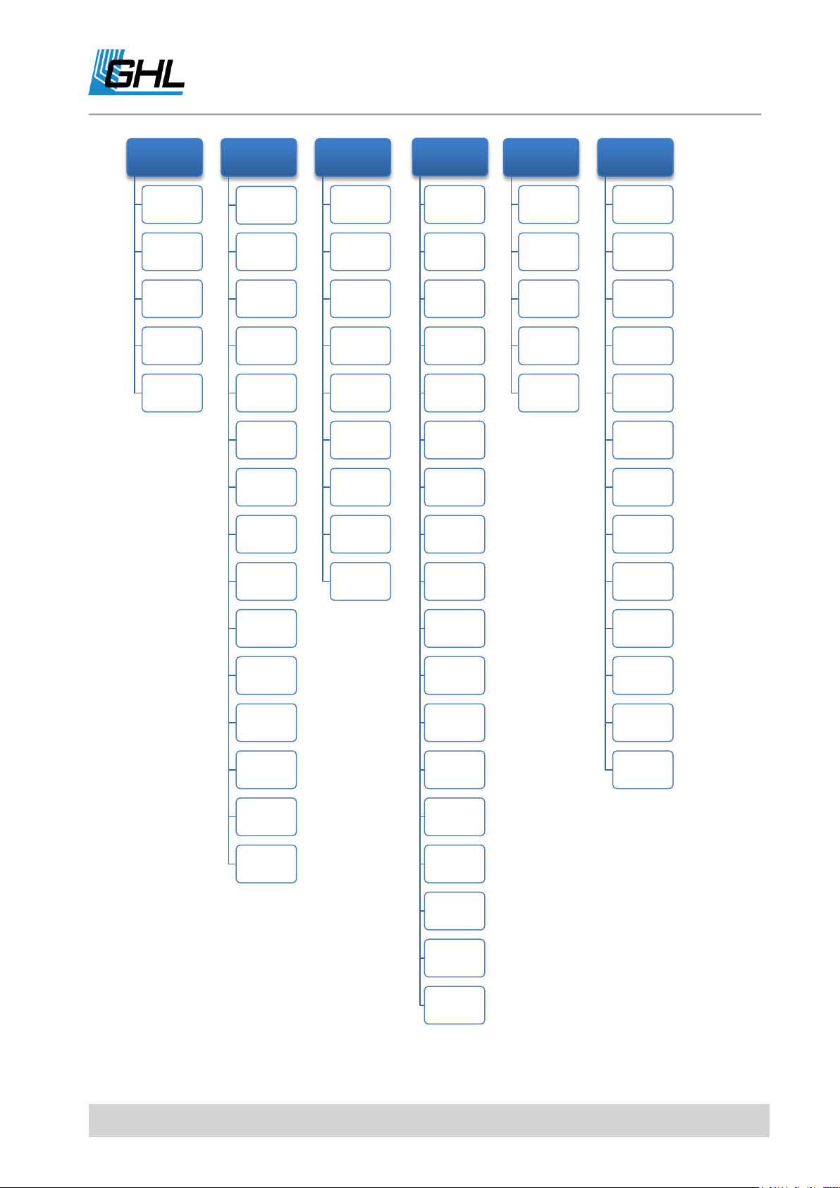
Below is the menu structure of the ProfiLux 4. These are the options available to you when
you operate the P4 through the device’s Control Pad. (This structure is also similar to the
layout seen in the PC-Software, GHL Control Center (GCC).
EN 2017-02-06 4
ProfiLux 4 Programming Guide
Clock
TIme & Date,
DCF
Reminders
Timers
Dosing
pump
Location
Illumination
Illumination
run
Manual
illumination
Clouds
Moon
Rainy days
Burning-in
Operating
hous
Storms
Temperature
-dependent
lightreductio
n
Variable
Illumination
Mitras
Lightbar
Lightdemo
Time lapse
Acclimation
Shift curves
Extras
Maintenance
Feeding
pause
Internal time
Info &
Support
Current
Eheim
Display
Measuremen
t data
Language
Sensor
settings
Activity
Nominal
value
Operation
hours
Hysteresis
Alarm
Nocturnal
change
Summer
switching
Therapy
Calibration
Display
Cooling
difference
Extension
Measuremen
t range
1-10 V maxi.
at
Density
offset
Current
actual value
Operation
mode control
Signalfilter
Level
Control
Input
Diagnostic
Start water
change
Error reset
System
Factory
settings
PIN
Socket outlet
function
1-10 V
interface
Program LED
Communikati
on
Alarm
Virtual
probes
Digital
powerbars
Configure
PTC
DALI
Digital inputs
myGHL
EN 2017-02-06 5

ProfiLux 4 Programming Guide
TIP
General note, tip or advice.
Preface
This manual is a supplement to the ProfiLux® 4 Instruction manual. This Programming
Guide is based on these operating instructions and cannot replace them in any
circumstances.
Get the Most out of your GHL Product
GHL products are well-equipped with simple and intuitive features. In order to get the most
out of our products, we recommend you read our Programming Guide and Instruction
Manual together. Doing so will provide you with the most profound details for using our
product. These documents can be downloaded from our website’s download area (Support-
>Downloads). Visit our homepage at www.aquariumcomputer.com , our Support forum or
visit us on Facebook to become a GHL-Product expert and fully utilize the full range of
functions offered from your device!
About this Programming Guide
The information provided by this guide is primarily based on setup and configuration via the
ProfiLux 4 display. When you configure the ProfiLux 4 via GHL Control Center, setup will slightly
differ from the descriptions shown in this guide. Individual settings are however, identically
displayed on the device and GHL Control Center.
Please read these instructions carefully before operating the ProfiLux 4.
GHL products are built with maximum security and safety in mind. However, product safety
for this device can only be guaranteed if you follow these guidelines.
Anyone who uses this device must become familiar with the following safety instructions and
the operation of the device.
Failure to follow these instructions will void any warranty claims.
In this manual, the following symbols are used:
EN 2017-02-06 6
ProfiLux 4 Programming Guide
WARNING
Important note for operation, to avoid damage to the equipment, and for
your safety.
WARNING
This equipment must not be used:
By small children and vulnerable persons with limited physical,
sensory or mental capabilities.
By people who are unfamiliar with the functions of this product.
DANGER
Warning that non-compliance can result in injury or damage to the device.
Safety Instructions
Intended Use
The ProfiLux 4 is exclusively for use in the domestic area. Only GHL accessories may be
connected directly to the ProfiLux 4 controller.
Make sure to keep the device away from splashing water, moisture or other liquids.
This controller is for monitoring and controlling aquarium functions and is exclusively for
indoor usage. ProfiLux 4 must be kept dry at all times.
For your own safety, please read the hazard prevention and safety instructions in the
chapters that follow. These precautionary tips are also found in the ProfiLux 4 Instruction
Manual.
1 Functionality and Operating Concept
1.1 Functionality of the P4
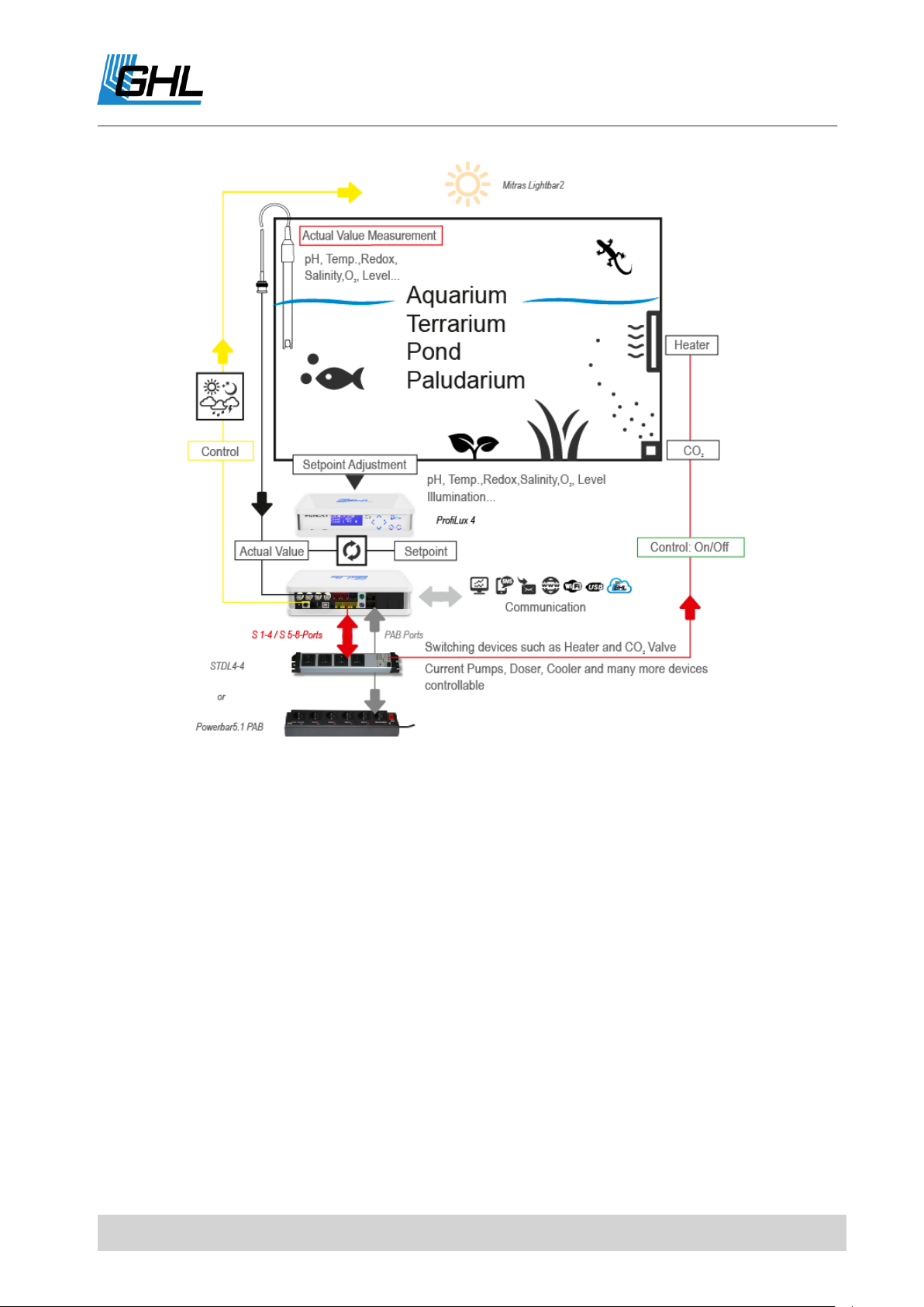
The following graphic gives you a rough overview of the functionality of the ProfiLux 4
Aquarium Controller. It also shows the interaction of the different system components.
EN 2017-02-06 7

ProfiLux 4 Programming Guide
DANGER
Please note the following:
The ProfiLux 4 Controller and its components (ProfiLux 4 System)
perform measurement, control, and control tasks based on your
settings.
There is no plausibility check of the settings you have made.
The controller's factory settings must be adapted to the
requirements of your aquarium.
You are solely responsible for the plausibility of your computer
settings and its system components.
The ProfiLux 4 Controller cannot replace the lack of expertise
required for the maintenance and maintenance of an aquarium or
terrarium.
Never leave your aquarium unsupervised for an extended amount of
time.
The ProfiLux System can help you with a large number of tasks and
display error conditions - but it cannot replace regular personal
supervision and control.
The maximum period of time without personal supervision depends
on how long your aquarium / terrarium can survive even in the event
of a fault without significant damage.
Always remember that technologies can fail and therefore,
malfunctions can never be ruled out!
Power failures, incorrect settings, damage (For example, by water or
overvoltage) or simply an unexpected operating situation can lead to
fatal damage.
The manufacturer disclaims any liability for (consequential) damages
or losses which might arise in connection with the use of the ProfiLux
System as legally permissible.
EN 2017-02-06 8
ProfiLux 4 Programming Guide
The diagram shows an example of the functionality of the ProfiLux System.
Sensors that are used for measuring various values such as Temperature, humidity, etc., are
connected to either the ProfiLux 4 or to corresponding ProfiLux Expansion Cards. Each of these
sensors are assigned to a control circuit where parameters such as Set-point, hysteresis,
nocturnal change, etc., can be set.
With the desired values and settings set, each sensor can then be assigned to control a
powerbar socket. For example, assigning a temperature sensor to a powerbar socket will
result in that socket switching on/off based on the set probe conditions.
EN 2017-02-06 9

ProfiLux 4 Programming Guide
TIP
When creating a command, it is useful to set the function first.
1.2 Operating Concept
The operating concept of the ProfiLux computer strictly differs between two sets of settings:
Settings of functions such as e.g. pH set point, illumination run of a luminaire or
behavior of pumps
Settings of hardware such as the behavior of a switch socket (if this switching socket is
assigned to a lighting, a timer or a temperature sensor) or the behavior of a 1-10 V
interface (this interface should be assigned to a lighting or a pump)
This concept is extremely flexible because a function can be changed largely independently
of the hardware assigned to it and vice versa the hardware can be changed largely
independently of the function.
This concept allows you, e.g. to select a different socket for switching your tubular heater,
while the corresponding temperature settings can remain unchanged.
1.3 Examples of Settings
For a better understanding, take a look at some setting examples that are commonly used.
1.3.1 How to setup Temperature control
1. Setting the function: Set the desired set-point temperature, see also Sensor Settings->
Nominal value.
2. Setting the hardware: Set the switch socket outlet (socket) to switch the heating
element, the substrate heater and the cooling system (if present). See also System->
Socket outlet function.
1.3.2 How to set the Illumination?
1. Setting the function: Set the illumination run as needed, see also Sensor Settings->
Nominal value.
2. Setting the hardware: Set which switch socket outlet (for non-dimmable luminaires),
also see under System-> Socket outlet function, or which 1 - 10 V interface (for
dimmable luminaires), also see under System-> 1- 10 V interface, or whether the Mitras
Lightbar interface (when controlling a Mitras Lightbar) shall respond to this
illumination run.
EN 2017-02-06 10

ProfiLux 4 Programming Guide
1.3.3 How to set the Level control?
1. Setting the function: Set the operating mode and the behavior of the level sensor, also
see under Level-> Control.
2. Setting the hardware: Set which switch socket outlet (socket) is to be switched from
the level control, see also under System-> Socket outlet function.
1.3.4 How to set the Current pump control?
1. Setting the function: Set the pump groups and the current pumps, see also under
Extras-> Current.
2. Setting the hardware: Set which switch socket outlet (for non-speed-variable pumps),
see also System-> Socket outlet function, or which 1-10 V interface (for speed-variable
pumps), and see also under System -> 1-10 V Interface should react to the Pump.
1.3.5 How to set Dosing or Timer activities?
1. Setting the function: First set the desired timer or dosing pump (note: only GHL Dosing
Pump Unit 1st generation, GHL Doser 2 is controlled via PAB!), see also under Clock->
Timers or under Clock-> Dosing pump.
2. Setting the hardware: Set which switch socket outlet (socket) is to be controlled by this
timer or dosing pump, see also under System-> Socket outlet function.
1.4 Features / Resources
The functional range of your ProfiLux 4 and, if applicable, your ProfiLux System is determined
by the available Expansion Cards, sensors, PAB devices and LED lights.
The total of all available inputs and outputs in the ProfiLux system is referred to as
resources.
1.5 Numbering and Display of Resources
All resources of the system are serially numbered by the ProfiLux Controller and this is always
carried out the same way.
The resources of the ProfiLux are numbered firstly, followed by the respective PAB devices in
order of their assignment such as Power Bars, Expansion Boxes, etc.
The numbering always starts with the internal resources of the ProfiLux, followed by the
resources of the module cards in the expansion slots according to their order in the slots of
the ProfiLux.
Then the resources of the first found and assigned PAB device will follow, after that the
resources of the second PAB device, etc.
EN 2017-02-06 11

ProfiLux 4 Programming Guide
2 Clock
Use the clock feature to make changes to all time-related settings. ProfiLux 4 uses the
astronomical hour count which divides the day into 24 h.
Two clocks are running the ProfiLux 4.
The first clock is a so-called real-time clock (RTC). It shows the actual ("our") time. This is also
the time normally seen on the display. In the event of a power failure, this clock runs on a
battery-backup.
The second clock runs in the device (internal). This internal clock controls the automatic
processes such as dimming, nocturnal decrease, timers, etc.
By default, both clocks run in sync with each other, except when the actual time (e.g.,
automatic or manual winter time / summer time) is adjusted. Then the internal clock is not
adjusted immediately, but within the set days. For example, a setting of 10 days results in
60:10 = 6 minutes daily.
2.1 Time & Date, DCF
First you will be asked if you want to use DCF (external radio clock receiver, available as an
accessory).
If you confirm with Yes, the time received by the radio receiver is used. If the reception is
sufficient, the setting of the date and time is superfluous, they are updated automatically.
If you are not using DCF, you can now optimize the clock accuracy by entering a correction per
day (from -59 s to 59 s). At 0 s (default setting) the clock runs without correction, otherwise
the adjusted second number is added (or subtracted) once per day.
Then you have the option to determine whether the ProfiLux clock should change between
the normal time (CET) and the summer time (CEST).
If this shall not be the case, then in your aquarium only the normal time will be valid (i.e. in
summer the clock will go wrong by one hour). This makes possibly sense if you would like to
avoid the clock change for your fishes and plants.
If you want a changeover, you can still adjust how many days the changeover is to be made.
If you use DCF, this smooth time adaptation starts beginning from the time of the CET-CEST-
change. If you don’t use DCF, then the time can be changed manually by one hour.
EN 2017-02-06 12

ProfiLux 4 Programming Guide
Note
The DCF signal for the radio clock is not always present.
Therefore it could happen that sometimes no reception is possible.
The internal clock continues to run and is synchronized again at the next
reception (possible minor deviations are corrected). Therefore DCF can also
be used with only occasional reception.
In this case also, the internal clock will be adjusted slowly within the set days. With this, you
are given the opportunity to spread this one hour over several days and you will have a
smooth time change.
After this you can then set the date and time manually.
When you save the time settings, you will be asked if you want to update the internal time
(see above).
If you confirm with Yes, the internal time is immediately set to the new time, otherwise the
internal time will be adjusted smoothly as explained above.
For initial time setting you should confirm with Yes. If you want to change clock due to
summer time, confirm with No.
2.2 Reminders
ProfiLux 4 can remind you of activities to be performed.
After a certain adjustable time (in days), the reminder text is displayed on the ProfiLux 4,
alternating with the standard display.
The reminder is displayed until you mark it as done. If you have set a repeated reminder, the
reminder will be displayed again after the new expiration time.
For example, a reminder can be set to be displayed every month to indicate a filter must be
replaced.
A single and repeating reminder can be set to display the desired text when requested.
After setting the reminder(s), ProfiLux 4 will display as a confirmation when the next reminder
will come about.
You can enter up to 16 reminder texts.
EN 2017-02-06 13

ProfiLux 4 Programming Guide
NOTE
You can use a timer for dosing purposes, but for more sophisticated
functions, we recommend using the dosing pump control, see
Clock ->Dosing pump.
Select the reminder (1 - 16) first.
Select whether the reminder should be enabled -> RETURN
If this reminder is currently up-to-date, you can mark it as done, it will not be
displayed any further.
If you have activated this reminder with Yes, you can set whether you want to be
reminded repeatedly.
You can then enter how many days you want to be reminded.
Then enter the reminder text.
Press the top arrow button on the control panel. The letter A appears. Press again to
display the letter B, press again to display C, and so on. The letters appear according
to their order in the alphabet. If you want to go back a letter (for example from C to B),
press the lower arrow key.
Press the left and right arrow keys to move the cursor to the right and left, and enter
additional characters or spaces.
When the text is finished, press RETURN and press YES. Safe with -> RETURN
After saving, ProfiLux 4 shows a confirmation when the next reminder is pending.
2.3 Timers
ProfiLux 4 has 32 freely programmable timers whose function you can adjust as described
below. The switch socket outlets (hardware), which are to react to the switching operations,
can be assigned as described under System-> Socket outlet function.
After selecting the timer that you want to program, the switching mode (function) needs to
be set. The following options can be selected:
Normal
This mode is used to program longer switching times (accuracy 1 minute).
The switching time (Duration) is set by entering the switch-on time and the switch-off time.
Short time
EN 2017-02-06 14

ProfiLux 4 Programming Guide
Min. wait time
Max. wait time
Result
Switch on 1
10s
20s
After 10 to 20 seconds is switched on
Switch off 1
60s
60s
After 60 seconds is switched off
Switch on 2
300s
1000s
After 300 to 1000 seconds is switched on
With this setting, short switching times (1s to 300s, accuracy 1s) can be realized. The
switching time is set by entering the switch-on time and duration.
Automatic dosing
As many Dosings per day will take place as it has been set before under Switching cycles per
day. The time points of the dosings are calculated automatically (they are spread evenly
throughout the day). The switching duration is calculated automatically on the basis of the
Flow rate of the pump and the Rate per dosing (see below).
Manual dosing
As many Dosings per day will take place as it has been set before under Switching cycles per
day. The time points of the dosings can be defined explicitly afterwards. The switching
duration is calculated automatically on the basis of the Flow rate of the pump and the Rate per
dosing (see below).
Event start
The timer initiates an operation such as e.g. A water change, see also under ->Level. Enter the
start time only.
Cyclic
This mode allows very special switching sequences. Please note that this mode can only be
selected and set via our PC program GCC (GHL Control Center)!
In this mode, the timer is switched on and off alternately, always after a certain waiting time
has elapsed.
The wait time after which is switched on is determined by random generator within the limits
of the minimum waiting time and maximum waiting time. If the waiting time should always be
the same, enter the same value for both times. The waiting time after which is switched off is
also determined by a minimum waiting time and a maximum waiting time.
One cycle consists of 1 to 4 pairs of switch-on and switch-off waiting times. After the last
switch-off of the cycle, the cycle starts from the beginning. All waiting times are adjustable in
the range from 1 s to 65535 s.
Example for a cycle with 2 switch-ons and switch-offs:
EN 2017-02-06 15

ProfiLux 4 Programming Guide
Switch off 2
1s
30s
After 1 to 30 seconds is switched off
Cycle starts from the beginning
Instructions for Dosing
The dosing amount per day corresponds to the Dosings/day and Rate/Dose.
For example, 4 doses per day with 10ml per dose will result in 40ml being
dosed per day.
Alternatively, you can also use a timer or a controller (e.g. pH-value or
conductivity) to control a dosing pump.
Due to tolerances, a pump’s flow rate on the data sheet can deviate from
the reality. To achieve the highest possible level of dosing accuracy, we
recommend you measure the actual flow rate of a pump (let pump run for 1
minute and measure the quantity of fluid pumped in this time) and set the
result of this measurement in Flow rate.
After that, you can enter the number of Switching cycles per day (0 up to 8; 0 means that this
timer is not active)
After setting the switching cycles, enter the Day mode:
Days of week
Here you can set the weekdays to be switched. A marked box means "Switching active on this
weekday", an empty box means "inactive ".
Interval of days
Here, the number of days after which the switching cycle is to be repeated is set, 1 day
means a daily switching cycle. After that you can set in how many days the switching shall be
started.
If you have selected a dosing switching mode, you must also enter the flow rate in ml /
minute.
Here, the actual pump power is needed. Based on this information, ProfiLux 4 calculates the
switch-on times of the dosing pump.
Changing this setting does not affect the pump performance - this is predefined by the pump
mechanism!
For an automatic dosing, you must also adjust the Rate per dosing.
A timer can activate a feeding pause, see at Extras-> Feeding pause.
EN 2017-02-06 16

ProfiLux 4 Programming Guide
2.4 Dosing Pump
ProfiLux 4 has 16 freely programmable dosing pump controllers, whose function you can
adjust as described below. The switching outputs (hardware) which shall react to the
switching processes can be assigned as described under System-> Socket outlet function.
Select the dosing pump you want to program and then set the Switching mode. Choose from
the following options:
1. Automatic dosing: This mode is suitable if you want to dose a certain amount of the
same quantity evenly over a certain time. A maximum of 150 doses per day are
possible
2. Manual dosing: This mode is suitable if you want to dose a certain amount at fixed
times during the day. For example, at 8:00 o'clock, dose 35 ml of XY. A maximum of 8
doses per day are possible.
Furthermore, you can determine whether you want to dose on specific weekdays or daily
intervals.
Day modes:
Days of week
Here, you can set the weekdays at which the switching should be carried out. Use the right
arrow key to select the checkboxes, to move on downwards press arrow down. A marked box
means "Switching on this day of week active", an empty box means "inactive". Confirm the
selection with ->RETURN.
Interval of days
Here, you can set the number of days by which the switching cycle/number of dosages are to
be repeated. 1 day means daily dosage. The maximum daily interval is 200 days. Be sure to
set the number of days until the switching/dosing shall start.
After that, enter the Flowrate of the Pump in ml/minute. Based on this information, ProfiLux 4
calculates the switch-on times of the dosing pump.
Changing this setting does not affect the pump performance - this is predefined by the pump
mechanism!
Automatic dosing
Set the number of doses per day. Use the arrow keys on the control panel to move the
cursor to the right or left. Enter numbers using the upper arrow key (counts up). Use
EN 2017-02-06 17

ProfiLux 4 Programming Guide
the lower arrow key to count back. Once you have entered the desired number,
confirm with ->RETURN. Up to 150 dosages are possible, 0 = No dosage.
Decide on which weekdays the dosages should take place or select the daily interval if
a dosing is to take place every day or every 2 days ... etc.
Enter the Flow rate of the dosing pump ->RETURN
Enter the dosing amount Rate per dosing ->RETURN
The dosing time points are calculated automatically (they are distributed evenly throughout
the day). The duration of the dosage is calculated automatically by means of the Flow rate of
the pump and the Rate per dosing (See below).
Manual dosing
Set the number of doses per day. A maximum of 8 dosings per day are possible -
>RETURN
Decide on which Days of week the dosages should take place or select the Interval of
days if a dosing is to take place every day or every 2 days ... etc. The maximum daily
interval is 200 days (see below).
Enter the flow rate of the dosing pump ->RETURN
Specify the time at which the first switching / dosing should take place
Enter the dosing amount Rate per dosing ->RETURN
Proceed with the further desired switching operations as with switching operation 1
There are as many switching cycles per day as was set at dosages per day before. The time
points of the dosage can be defined explicitly in the following. The switching time is
calculated automatically by means of the Flow rate of the pump and the Rate per dosing. (see
below).
If you have selected Automatic dosing, the first dosing of the day is usually made at 0:00. With
Always dose at (this time) you have the possibility to determine the time of the first dosing. All
other doses are distributed throughout the day
The following features are only available via GHL Control Center, Web Interface, App and cloud
service myGHL:
The dosing pump control has a level monitoring. When the pump is active ProfiLux 4
calculates the new filling level.
For this purpose, the Capacity of the container as well as the minimum amount must be
entered.
EN 2017-02-06 18

ProfiLux 4 Programming Guide
Instructions for Dosing
The dosing amount per day corresponds to the Dosings/day and Rate/Dose.
For example, 4 doses per day with 10ml per dose will result in 40ml being
dosed per day.
Alternatively, you can also use a timer or a controller (e.g. pH-value or
conductivity) to control a dosing pump.
Due to tolerances, a pump’s flow rate on the data sheet can deviate from
the reality. To achieve the highest possible level of dosing accuracy, we
recommend you measure the actual flow rate of a pump (let pump run for 1
minute and measure the quantity of fluid pumped in this time) and set the
result of this measurement in Flow rate.
If Alarm when below is activated ProfiLux 4 outputs an alarm. Before an alarm is issued
ProfiLux 4 will give a warning.
If the container is refilled, the replenished quantity can be entered, a possible alarm will be
reset if there is sufficient refilling.
2.5 Location
The coordinates (Longitude and Latitude) of your location can be entered here. This
information will be used for further simulations in the future.
From the factory, this is 49.4 ° N and 7.8 ° E - the coordinates of Kaiserslautern in Germany -
the production location of your ProfiLux 4.
3 Illumination
This menu contains all lighting-related settings and functions.
ProfiLux 4 can control 32 dimmable or non-dimmable lamps independently. Lighting units
can be switched via our powerbars. Dimmable lighting units can be also controlled via the 1-
10V interfaces. The dimmable LED Mitras Lightbar is controlled via its own digital interface.
Dimmable tubular lightbars are controlled by L1 (or L3, L5, etc.) as standard. It controls both
tubes of that lightbar.
You also have the option to simultaneously dim tubular lightbars.
EN 2017-02-06 19

ProfiLux 4 Programming Guide
TIP
If required, you can retrofit additional 1-10 V interfaces with ProfiLux
Expansion Cards, PLM-4L or PLM 2L4S.
NOTE
The brightness curve between the individual dim-points are calculated
automatically.
You can set the illumination run for each lighting individually. This makes it possible to
achieve effects like sunrise or moonlight.
3.1 Illumination Run
Please select which lighting is to be edited (Illumination to edit?). After selecting a lighting, you
can set the type of the luminaire, dimmable and non-dimmable.
It is also necessary to specify whether the automatic is to be switched on (Automatic on?). If
this is not the case, this lighting is in manual mode. Select whether you want a temperature-
dependent light reduction.
Enter the number of dim-points (for dimmable luminaires) or the switch-times (for non-
dimmable luminaires) for which you want to adjust the brightness (up to 24)
If you have selected a dimmable luminaire, please set the following for each dim-point:
Time – At this time, the luminaire shall have the brightness to be set subsequently
Light intensity (0% - 100%) – Brightness of the light at this time
If you have selected a non-dimmable luminaire, please set the following for each dimming
time:
Switch on – The light is switched on at this time
Switch off – The light is switched off at this time
Then select which simulations should affect this lighting process and save the settings with
Yes ->RETURN.
EN 2017-02-06 20

ProfiLux 4 Programming Guide
TIP
To create/edit your Illumination run, we recommend using GCC Light
Composer. Light Composer provides the quickest solution for creating your
own lighting schedule.
The Light Composer calculates the individual lighting channels by means of
the desired brightness and color sequence over the day.
You can download that free of charge software on our homepage (Support-
>Downloads) www.aquariumcomputer.com.
The following functions can only be set via GCC.
3.2 Copy an Illumination Run using GCC
With this function, you can spare yourself the time of having to enter the same illumination
run settings again and again, especially if several illumination channels shall do the same.
If you activate Copy illumination run, you still have to enter the illumination channel from
which the run shall be copied. The entry of an illumination run on which you are just working
is then not necessary anymore (resp. also not possible anymore). This illumination channel
follows exactly the illumination run of the channel from which you would like to copy,
potentially time-shifted when you use the following functions.
3.3 Time shift with GGC
This function is used to allow an illumination channel to follow its set course or darkening
during clouds in a time-delayed manner. The time shift can be set separately for the
illumination run and for clouds. The time shift also has an effect when the illumination run
has been copied.
3.3.1 Time shift during clouds
With this function, sliding clouds that pull over several luminaires are possible.
This time, adjustable from 0 s to 3.1 s in steps of 0.1 s, determines with which delay the
illumination channel should be darkened during a cloud. The brightening at the end of a
cloud is delayed by the same time. If you have several dimmable luminaires that can be
separately controlled, you can use this function to create even more realistic clouds.
EN 2017-02-06 21
ProfiLux 4 Programming Guide
Illumination
channel
Time shift during
clouds
Effect
1
0s
Light is darkened immediately in case of a cloud
2
0.5s
Light is darkened after a delay of 0.5 s in case of a cloud
3
1s
Light is darkened after a delay of 1 s in case of a cloud
Before the cloud
Cloud starts
Cloud is fully there
Cloud fades away
After the cloud
Illumination
channel
Time shift for
illumination run
Illumination run
Effect
1
0
Channel has its own
illumination run
Follows directly illumination run 1
2
10 Minutes
Copy of 1
Follows illumination run 1 delayed by 10
minutes
3
20 Minutes
Copy of 1
Follows illumination run 1 delayed by 10
minutes
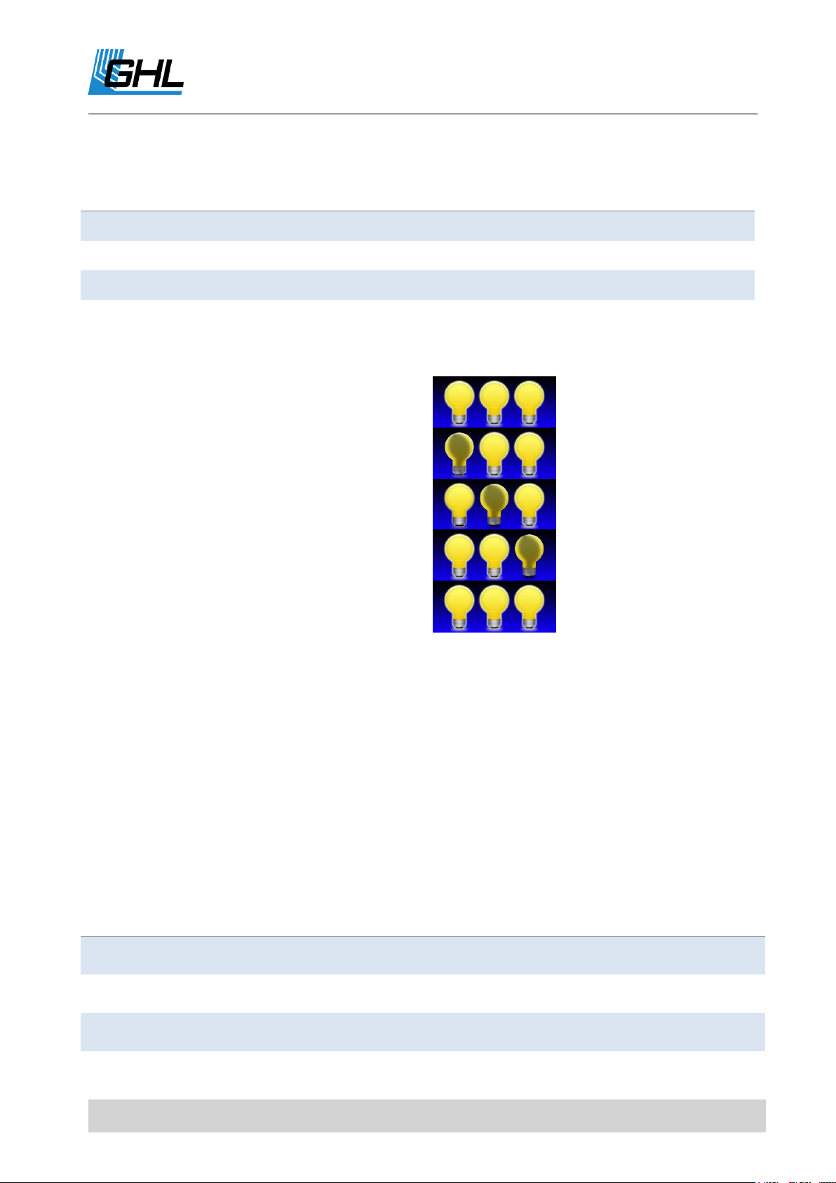
Example with 3 dimmable lights:
The following graphic illustrates the effect:
3.3.2 Time shift for Illumination Run
This time indicates the delay with which this lighting channel should follow its (or copied)
lighting curve (adjustable between 0s and 1h). With this function, it’s possible to distribute
switching on (or dimming up) and switching off (or dimming down) to several luminaires.
If you want your luminaires to have the same illumination run, only a little bit time-delayed,
the following procedure is recommended.
Example with 3 dimmable lights:
EN 2017-02-06 22

ProfiLux 4 Programming Guide
Before sunrise
Sunrise starts
Sunrise is advanced
Sunrise is complete
Sunset starts
Sunset is advanced
The sun has completely set
Symbol
Meaning
Dimmable only upwards (at 0%)
Dimmable only downwards (at 100%)
Dimmable in both directions
The following graphic illustrates the functional principle:
3.4 Manual Illumination
This menu is mainly used for testing and diagnostic purposes. With the arrow keys left right,
you can select the lighting channel whose brightness you want to adjust, 4 channels are
displayed simultaneously. Use the up and down arrows to make the channel brighter or
darker.
The symbols displayed to the left and right of the selected channel have the following
meanings:
Save your settings and exit the manual brightness setting by selecting Esc.
EN 2017-02-06 23

ProfiLux 4 Programming Guide
3.5 Clouds
ProfiLux 4 can simulate passing clouds by using a random generator. When a cloud passes, all
of the involved luminaires temporarily become darker as the simulation goes through its
effect.
The maximal waiting time (0s - 100s) determines how long the time intervals between two
clouds should be (with 0s the cloud simulation is switched off). The random number
generator waits between 1s and the maximal waiting time until a new cloud is generated.
Furthermore, the minimal and maximal cloud duration as well as the maximal darkening (10% -
95%) are to be set. The random generator generates new clouds, taking these values into
account.
The cloud simulation also works with simultaneous lunar phase simulations and during a
dimming process.
Note that the cloud simulation must be active for the desired illumination channels, see also
-> Illumination run.
3.6 Moon
ProfiLux 4 simulates the moon phases depending on the date.
In reality, the lunar cycle is a very complex matter:
Thus the distances vary from new moon to new moon. On average it is about 29.5
days.
Likewise, the moonrise time as well as the distance to the earth differ respectively.
It is not the fact that at half-moon the moon has 50% of its brightness. We consider on
average about 25%.
Our lunar phase simulation does not aim to replicate these complex sequences in every
detail. For us, it was important to produce a repeating moonlight sequence which would
illuminate the aquarium somewhat differently day-to-day. We’ve implemented such features
to provide a certain rhythm which would largely be in harmony with nature.
Lunar phases created by the ProfiLux 4 are based on the calendar date so that full moon and
new moon phases always correspond to the actual (real) lunar phase with a deviation of one
day or less.
You can set the time when the lunar phase simulation is active. In order for the lunar phase
simulation to function, it must first be activated in the desired lighting channels.
EN 2017-02-06 24

ProfiLux 4 Programming Guide
With the lunar phase simulation enabled on the selected lighting channels, the following
happens within the set time: The brightness (given by the set illumination run) is multiplied
by the calculated moon phase brightness. The illumination run is therefore still taken into
account.
The result is for example, at half-moon (= 50% lunar phase, 25% lunar brightness) and a
brightness of 30% (given by the illumination run). A luminaire brightness of 25% * 30% =
7.5%.
Illumination channels, without activated moon phase are not affected and follow their
lighting curves as normal.
Outside of the set simulation time, no illumination is influenced by the lunar phase
simulation.
With this method, it is possible to normally operate a lighting channel during the day (outside
the set simulation time/no influence of the lunar phase) and in the evening with the moon
phase (within the set simulation time).
The start and end-time of the lunar phase simulation should be created so that the night
illumination interval of the assigning lighting is included.
If the illumination of a luminaire is for example, programmed to illuminate as moonlight
from 19:00 (7:00pm) to 7:00 (7:00am), moon phase simulations should also be set from 19:00
(7:00pm) to 7:00 (7:00am).
The lunar phase simulation can also be tied-in with other simulations.
3.7 Rainy Days
ProfiLux 4 allows the programming of "Rainy days". On a rainy day, the lighting intensity is
reduced by an adjustable value.
With this feature, you have the option to set the weekdays for which Rainy Days should be
enabled. Once the days have been selected, the darkening of the day has to be set (0% -
100%).
The Rainy days simulation also takes other simulations into account.
3.8 Burning-in
Fluorescent tubes must be burned in before they can be used for dimming. ProfiLux 4
provides a convenient way to automate the burn-in process.
EN 2017-02-06 25

ProfiLux 4 Programming Guide
After selecting the Illumination to which the tube to be burnt-in is connected, the burning in
period can be set between 0h and 100h.
This lighting is then only operated with 0% or 100% until the operating hours meter (see also
-> Operating hours) has reached the burn-in period for this lighting (all dim-settings from 1%
are automatically output as 100%).
At 0% the lamp will be still switched off - the burn-in is done step by step.
By default, the burn-in time is set to 0 h, so the burn-in is deactivated.
3.9 Operating hours
Each lighting channel includes its own operating hours meter, which continues to run when
the corresponding lighting is active (brightness greater than 0%).
This feature continuously tracks the length of time a light is in operation so you always know
how when it should be exchanged. It is especially useful for preventing performance
decreases due to bulbs aging.
The operating hours counter is also used by the burn-in program. The operating hours are
written cyclically every 1h into the non-volatile memory. This ensures that the operating
hours are maintained even in the event of a power failure.
After selecting the menu item Operating hours, please select the Illumination option. The
operating hours for this Illumination are then displayed.
After a few seconds or by pressing a key, you will be asked if you want to “reset the operating
hours meter?” A confirmation with Yes resets the operating hours counter to 0 h. Of course,
this should only be done when changing the light source.
3.10 Thunderstorms
ProfiLux 4 can simulate an authentic thunderstorm.
When a thunderstorm simulation is in-effect, a slow reduction of all illumination channels will
occur. As these channels become darker, the number of flashes will increase. After the
thunderstorm has reached its climax, the lighting is slowly brought back to normal strength,
the flashes become less frequent until finally the thunderstorm is over.
A thunderstorm can be started manually any number of times or automatically up to 4 times
per day. There is also an option to start a thunderstorm at random.
Set the thunderstorm parameters in the Storm menu:
EN 2017-02-06 26

ProfiLux 4 Programming Guide
NOTE
The signals necessary for a thunderstorm can only be generated from the
onboard 1-10 V interfaces (L1 to L6) or from the Mitras Lightbar connector.
A "thunderstorm illumination" should therefore not be connected to
possibly existing additional 1-10 V interfaces (for example expansion card
PLM_2L4S)!
Darkening (0% - 100%) during a thunderstorm
Intensity (1 – 20) of the thunderstorm – Higher numbers, the more flashes are generated
Flash brightness (10% - 100%) – Determines the LED output power during a flash
Thunderstorm/Day – Number of automatically generated thunderstorms in a day (max. 4)
Weekdays – Only on these weekdays there is a thunderstorm
Start 1...4 – A thunderstorm begins at this time
Duration 1...4 – Duration of a thunderstorm (1 to 60 minutes)
Random thunderstorm duration – If you want random thunderstorms, enter a duration (max.
60 minutes) for the random thunderstorm (If you enter 0, randomly generated
thunderstorms are disabled).
Waiting time minimal and maximal – the random generator determines a waiting time within
these limits (maximum 240 hours) until the next random storm is started.
In the Thunderstorm menu, a thunderstorm could be manually started by selecting Manual
Start. The duration (1 to 60 minutes) must then be entered here. When a manual
thunderstorm is triggered, the stored thunderstorm intensity and darkening Settings are
used.
3.11 Temperature-dependent light reduction
With this function, it is possible to gradually reduce the lighting (in the case of dimmable
luminaires) or switch it off (in the case of non-dimmable luminaires), depending on whether
the nominal temperature is exceeded.
When calculating the reduced light intensity of dimmable luminaires, the current illumination
run as well as possible simulations are included.
EN 2017-02-06 27

ProfiLux 4 Programming Guide
Actual temperature
Light reduction by
Actual temperature
Light reduction by
28.5 °C
25 %
29.5 °C
75 %
29.0 °C
50 %
29.0 °C
100 %(Off)
Example for Dimmable Lamps
Nominal temperature = 26.0 °C, min. temperature excess = 2.0 °C, max.
temperature excess = 4.0 °C, this results in the following table
With the temperature-dependent light reduction, it is possible to prevent your aquarium
from being further heated by the illumination on hot summer days. This feature is especially
useful when an existing cooling system cannot provide sufficient temperature reduction.
The following parameters can be set:
The determining Temperature sensor (for example, temperature 1 if you have
connected one temperature sensor. If you connected more than one, select the
sensor to be used for the measurement).
The Temperature excess minimal – If the nominal temperature is exceeded by this
value, then the reduction of the illumination intensity of the affected lamps begins,
adjustable from 1 °C up to 5 °C - this setting is only relevant for dimmable lamps!!
The Temperature excess maximal – If the nominal temperature is exceeded by this
amount, the lighting concerned is switched off completely, adjustable from 2 °C to 10
°C, must be at least 1 °C higher than the minimum temperature limit - this setting is
only relevant for dimmable luminaires!
The Shut off limit – If the nominal temperature is exceeded by this amount, non-
dimmable luminaires are switched off. A value between 1 °C and 10 °C is adjustable.
These lights are not switched on again until the programming of the corresponding
illumination run defines again a switch on (luminaire has been switched off according
to the programming, for example at night - and is switched on again, for example in
the morning). A drop in the temperature alone does not lead to a new switch-on,
which is particularly useful with gas discharge lamps, since these should not be
switched on and off continuously. This setting is only relevant for non-dimmable
luminaires!
EN 2017-02-06 28

ProfiLux 4 Programming Guide
Example
You would like to have for the illumination from Monday to Friday other
settings than for Saturday and Sunday, so you need 2 different illumination
runs.
First you set both illumination runs (e.g. illumination run 1 for Monday to
Friday and illumination run 5 for Saturday and Sunday) according to your
wishes.
Afterwards you set e.g. Variable Illumination 1 accordingly (Monday: 1,
Tuesday: 1, …, Friday: 1 and Saturday: 5 and Sunday: 5).
Finally you choose the function Variable Illumination 1 as function for the
corresponding 1-10 V-interface (see also System ->1-10 V interface) resp. for
the corresponding switchable socket (see also System ->Socket outlet
function.
3.12 Variable Illumination
This function allows you to use different illumination runs for a luminaire on different
weekdays.
Up to 16 variable lighting programs can be defined. After selecting the program (1 to 16), you
can set for Monday to Sunday, which lighting sequence (1 to 16, Illumination run) should be
used on the respective day.
3.13 Mitras Lightbar
Activate this setting when you have connected our Highpower LED Illumination Mitras®
Lightbar. You can also specify which of the available serial interfaces (usually COM1) are to be
used to control the Mitras Lightbar.
Here you can change the output power of the Mitras Lightbar.
3.14 Light demo
The Lightdemo serves for demonstration purposes. After activation, the LEDs are alternately
dimmed up and down.
With the keyboard the Lightdemo can be varied:
Arrow up and down – Color change faster or slower
Arrows left and right - Change the color pattern
Return - Freeze the current color pattern, press Return again restarts the automatic
sequence
EN 2017-02-06 29

ProfiLux 4 Programming Guide
Esc finishes the light demo.
3.15 Time lapse
The Time lapse can be used for test and demonstration purposes. With this function you can
view the adjusted illumination run in time lapse.
There is a manual time lapse (indicated by an M in the upper right) and an automatic time
lapse (indicated by A). You switch between both modes by pressing Return.
In manual time-lapse, you can set the time to be simulated, at which the appropriate lighting
is to be displayed.
During the automatic time-lapse, the time to be simulated is constantly incremented, you can
set the speed of the time-lapse. Set the duration, in seconds, to be used for 24-hour
simulation.
Esc finishes the time-lapse.
3.16 Acclimation
The acclimation function provides a simple and comfortable way to automatically change the
brightness of the light over a span of several days. We recommend using this simulation for
acclimating corals/plants to a new lighting program or when corals have been newly brought
in.
After activating, the following settings can be made:
Start date – The acclimation period begins on this day
Start percent- With this value, all dimmable lights are multiplied at the beginning of the
acclimation
End date - The acclimation period ends on this day
End percent - With this value, all dimmable lights are multiplied at the beginning of the
acclimation
During acclimatization, a dimming factor is calculated daily. The individual illumination runs
are converted according to this factor.
Example: Start on 01.12.2016 (12-01-2016) with 50%, end on 03.12.2016 (12-03-2016) with
100%
EN 2017-02-06 30

ProfiLux 4 Programming Guide
Note
In order to achieve maximum flexibility, the settings of the maintenance
function refer directly to the hardware (switch sockets and 1-10 V interfaces)
...
...and not on control and regulation functions (e.g., temperature control or
illumination channels).
Then the lighting channels are operated with 50% of the normally set brightness on the
01.12.2016 (and also before), on the second day with 75%, and on the last day with 100%
(and also thereafter).
Starting and ending percentages can be adjusted as needed; thus an increase as well as a
lowering over a certain period of time is possible..
3.17 Shift Curves
This function allows you to move complete illumination runs.
Select the illumination(s) whose illumination run(s) you want to move.
Then determine the time offset and confirm with ->RETURN
4 Extras
Special functions and settings are summarized here. The following submenus are provided.
4.1 Maintenance
During the maintenance and care of the aquarium, it can be helpful to set the switch state of
some switch sockets or the brightness of luminaires explicitly.
An example would be switching the heaters off, setting the flow to minimum and setting a
dimmable lightbar to 80%.
ProfiLux 4 offers 4 separately adjustable Maintenance programs.
In the Maintenance menu, you can set the maintenance parameters under Settings. For quick
access, the maintenance programs are positioned on top, one after the other. The menu
item Settings will show up afterwards. Scroll down the menu until you reach Settings. Then
select the Maintenance program you want to edit.
Set affected 1-10V interfaces
EN 2017-02-06 31

ProfiLux 4 Programming Guide
Here you can select the 1-10V interfaces to be affected during maintenance. All non-selected
interfaces continue to operate normally and program-controlled during maintenance.
Adjust affected 1-10V interfaces
For the previously selected 1-10V interfaces, you can set here which voltage in percentage
they shall output during the maintenance.
Select affected socket outlets
Here, you can set which sockets should be influenced during maintenance. All unselected
sockets continue to operate normally and program-controlled during maintenance.
Adjust affected socket outlets
The switch state (on or off) can be set for the previously selected sockets during
maintenance.
The following two settings are available only if a Mitras Lightbar is connected.
Select affected Mitras Lightbar LEDs
Here it is possible to adjust which LEDs of Mitras Lightbar are to be influenced during
maintenance. All non-selected LEDs continue to operate normally and as programmed
during maintenance.
Adjust affected Mitras Lightbar LEDs
For the previously selected LEDs, the brightness can be adjusted as a percentage during
maintenance.
Maximum length maintenance
This time (up to 240 minutes) determines the length of time the maintenance is
automatically switched off.
The automatic shutdown after a certain period of time prevents maintenance from
remaining permanently active if you forget to switch it off again. If maintenance is allowed
for an indefinite period, enter 0 here.
Activate the Maintenance program in the Maintenance menu with Start.
While the maintenance program is active, the selected sockets have the set switching states
and the selected 1-10 V interfaces output the set voltages.
ProfiLux 4 signals an active maintenance program with a blinking hammer symbol in the
display.
End the Maintenance program from the Maintenance menu by selecting Stop.
EN 2017-02-06 32

ProfiLux 4 Programming Guide
Note
During maintenance, the alarm monitoring of all sensors is switched off!
Note
To avoid damage to the microbiological climate of your filter, do not select
this time longer than absolutely necessary (approx. 5 to 10 minutes)!
4.2 Feeding Pause
ProfiLux 4 offers 4 independent feed pauses, which can be started and set in the feed pause
menu.
Scroll down in the Feed Pause menu until you get to Settings.
Select the feed pause (1 to 4) whose settings you want to adjust.
Set the duration of the feed pause (length feeding pause). This determines how long the
activated feed pause takes, which has been started manually with the Esc key or
automatically by a timer. It can be set between 0 and 120 minutes (0 means that this feed
pause is not used).
Furthermore you can set which effect the feeding pause shall have:
Stop filter? – with the selection of Yes the switchable socket with the function Filter (1 to 4,
depending on the feeding pause you are editing here) will be switched off during the feeding
pause.
Finally, you have to set whether a timer can activate the feed pause, if Yes is selected, choose
which timer should start this feeding pause.
If a timer should activate this feeding pause then the feeding pause is activated as long as
this timer is active. The feeding pause remains furthermore active for the time set under
Length feeding pause. This makes sense, if this timer controls an automatic feeder or a dosing
pump.
The behavior of the current pumps during the feeding pause can be defined in the settings
of the current pumps (Extras->Current->Pump settings).
EN 2017-02-06 33

ProfiLux 4 Programming Guide
You start a feed pause by pressing the Esc key. If more than one feed pause is used, then the
appropriate feed pause has to be selected. The food pause can be interrupted by pressing
Esc again.
4.3 Internal Time
This function is used to display the internal clock (see also ->Clock). This function is only for
diagnostic purposes, settings cannot be made here.
4.4 Info & Support
After selecting this menu item, information about the software version, model and our
homepage is displayed one after the other (automatically after the lapse of a certain time or
by pushing a key).
4.5 Current
ProfiLux can control (current) pumps in a variety of ways; subsequent pumps are suitable for
control:
• Pumps with an analog control signal input (mostly 1-10V-interface), such as those
from Tunze®, Royal Exclusiv® or Abyzz®, are connected to a 1-10V interface port of
the ProfiLux (for the connection to ProfiLux you need the corresponding accessory)
• Pumps whose speed is adjustable via phase controlled modulation (therefore our
dimmable powerbar Powerbar2Dim is necessary)
• EcoTech®-pumps of VorTech® (with our module VorTech-Controller)
• Electronical external filter Professionel 3e® from Eheim® (with our module Eheim-
Controller)
• Some low-voltage pumps, e.g. Koralia® from Hydor® (with our module PumpControl1)
Furthermore, non-controllable pumps can be switched via switchable sockets, see also
System-> Socket outlet function. These can then of course only be switched on or off but not
regulated.
The current control is organized in groups, one group consists of one or several pumps. The
settings can be made separately for each group and for each pump. The group settings
define the pumps belonging to the group, the operational mode and the time settings
(depending on the operational mode).
For each pump, settings such as wave duration, minimal or maximal speed or the behavior
during the feed pause can be set individually.
EN 2017-02-06 34

ProfiLux 4 Programming Guide
Note
"Pump active" means that the pump is running continuously between min.
and max. current speed and thus generates waves.
A socket assigned to the flow pump is then switched on.
"Pump inactive" does not necessarily mean that the pump is off, but that it
runs at its minimum power.
A socket assigned to the flow pump is then switched off.
The group settings determine when and for how long which pump is active
in this group, the pump settings determine the behavior of the pump during
activity and inactivity.
4 independent groups can be programmed. A group consists of up to 4 (or up to 16) pumps
which can be independently controlled.
4.5.1 Nocturnal Change
For the current simulation, a Nocturnal change of the pump power can be adjusted. If the
Nocturnal change is activated, the start and end times must also be entered. Within these
times, the pumps are operated with the power set for the night. The night change affects all
pumps in all groups.
4.5.2 Group Settings
The following parameters can be set for each group:
4.5.2.1 Operational Mode
Here you can set the operating mode for a group. The individual groups may have different
operating modes.
Off – The pumps of this group are permanently off.
Permanent – The pumps are permanently active and run synchronously.
Permanent alternating – The pumps are permanently active and operate alternating, i.e. if
pump 1 runs at maximum speed, pump 2 runs at minimum speed and vice versa.
Sequence 1 – Here, always exactly one current pump of this group is switched on alternating.
The duration for the change from one pump to the next one can be set, see below. When the
last pump of this group was active, the cycle starts again with the first pump of this group. If
this group consists of 2 pumps, then the ebb-tide-simulation is generated. If only one pump
belongs to this group, it is switched on and off alternating.
EN 2017-02-06 35
ProfiLux 4 Programming Guide
Step
Pump 1
Pump 2
Pump 3
1
on
off
off 2 off
on
off 3 off
off
on 4 on
off
off 5 off
on
off 6 on
off
on 7 on
off
off
Step
Pump 1
Pump 2
Pump 3
1
on
off
off
2
off
on
off
3
off
off
on 4 off
on
off 5 on
off
off 6 off
on
off 7 off
off
on
Step
Pump 1
Pump 2
Pump 3
1
on
off
off 2 on
on
off 3 on
on
on 4 off
on
on
5
off
off
on 6 off
off
off 7 on
off
off
For a group with 3 pumps, the following switch-on pattern is obtained:
etc.
Sequence 2 – Similar to Sequence 1, but the pumps are not switched one after the other,
instead of that, they are activated in an alternating order.
For a group with 3 pumps, the following switch-on pattern is obtained:
etc.
Surge 1 – The pumps of this group are switched on one after the other until all pumps are
active, then the pumps are switched off again in the same order until all are off. The time
until the switching state changes again can be set (see beneath).
For a group with 3 pumps, the following switch-on pattern is obtained:
etc.
Surge 2 – Similar to Surge 1. This setting allows all pumps to be switches off in the reverse
order as they were previously switching on.
EN 2017-02-06 36
ProfiLux 4 Programming Guide
Step
Pump 1
Pump 2
Pump 3
1
on
off
off
2
on
on
off 3 on
on
on 4 on
on
off 5 on
off
off 6 off
off
off 7 on
off
off
WARNING
If a switching socket is to control the corresponding flow pump, the time
period must not be too small - otherwise too frequent switching can lead to
damage to the socket or the pump!
etc.
Random – Using a random generator, all, some or none of the pumps belonging to this group
are activated in a continuous random variation. The time until the switching state changes
again can be set (see beneath).
4.5.2.2 Assign Pumps
Here you can define which pumps belong to this group. A pump must not be assigned to
several groups.
4.5.2.3 Tide Duration
In the modes Sequence, Surge or Random you can set the time after which the switch on state
of the pumps shall change again. Enter a Minimal and a Maximal tide duration.
The time after a new switch-on state is to be assumed is determined by random-number
generator in the range of these two times.
Shall the time be always the same, the same value must be entered for Minimal and Maximal
tide duration.
The Minimal and a Maximal tide duration is adjustable between 1 second and 8 hours.
4.5.2.4 Wave
The type of wave generation can be set individually for each group:
EN 2017-02-06 37

ProfiLux 4 Programming Guide
0%
10%
20%
30%
40%
50%
60%
70%
80%
90%
100%
0 2 4 6 8 10 12 14 16 18 20
Output [%]
Time [s]
Controllable pump
Note
Waves have no effect on non-controllable pumps, which are connected via
switchable sockets.
Sinus waves – Gentle acceleration and slowing down of the pump
Right-angled waves – abrupt changes
Then set the Minimal and Maximal wave duration in a range of 0.4 and 60 seconds.
The random number generator determines a duration within these limits for each wave.
If all waves should have the same duration, enter the same values for Minimal and Maximal
wave duration.
The technical possibilities of the pump must, of course, also be taken into consideration for
the wave duration.
Finally, the random wave reduction can be set from 0% to 100%.
The bigger the value, the more different the single wave crests become.
At 0%, each wave peak reaches the maximum (wave crests are always equal),
At 100%, the wave waves fluctuate randomly between minimum and maximum.
In the following, the flow pattern can be seen on a controllable pump (settings: Minimal =
30%, Maximal = 90%, Wave duration = 10 s, Wave form = Sinus):
EN 2017-02-06 38

ProfiLux 4 Programming Guide
4.5.3 Pump Settings
The following settings can be made individually for each pump:
Minimal - minimal power (during a wave trough or if pump inactive)
Maximal – maximal power (during a wave crest)
Night – maximal performance during nocturnal change
Storms – maximal performance during a storm
Behavior while feeding pause – adjustable is
uninvolved (Feeding pause does not affect this pump),
at minimum (pump is operated only with minimum
power during the feeding pause)
or off (pump is switched off during the feeding pause).
4.6 Eheim
With the accessory ProfiLux EHEIM controller, it is possible to connect an Eheim type
Professional 3e external filter to ProfiLux 4.
ProfiLux 4 is then able to control the flow rate of the external filter as a function of a flow
pump channel.
The external filter then follows within the scope of the technical feasibility - the flow rate of
an external filter cannot, of course, be changed as quickly as that of a current pump – to the
active current of the selected pump channel.
Here all functions of the current pump control of the ProfiLux, like e.g. Nocturnal Decrease or
Feeding Pause, are available.
Proceeding:
First set up a pump group and current pump according to your requirements.
After that you can make the following settings in the Eheim menu:
EHEIM-Controller connected – Selection of Yes required for ProfiLux 4 to control the
ProfiLux EHEIM controller
Current pump – Select the channel of the flow pump which is to control the flow rate
of the EHEIM external filter
EN 2017-02-06 39

ProfiLux 4 Programming Guide
WARNING
Select EHEIM controller connected only if you have actually connected a
ProfiLux EHEIM controller, otherwise the PC communication with RS232 will
be disturbed!
Note
You can display the actual flow and the days up to the next filter cleaning on
the ProfiLux display, see menu item Extras-> Display.
4.7 Display
Here, you can set which current values should be displayed on the display during normal
operation.
If several elements are selected, they are displayed alternately. These settings also affect the
display on a possibly connected ProfiLux Touch.
The following setting options are available in this menu:
Display duration– Time the display remains constant until the next value is displayed
Select illumination– Here you can select which lighting channels are to be displayed
Select controller (only if measurement inputs are available) – Select the controllers
whose values and states are to be displayed (e.g. pH and temperature)
Select miscellaneous – Selection of other elements that can be displayed (e.g., moon
phase, level, flow sensor, or EHEIM)
Time & Date – It can be set whether the current time and the date are displayed never
always or rotating.
4.8 Measurement Data
ProfiLux 4 can record measurement data.
Storage size – Max- 8192
Memory type – FRAM (nonvolatile memory), in case of a voltage supply failure the
measured values keep stored
If the measurement value storage is full, then the oldest data is overwritten.
EN 2017-02-06 40

ProfiLux 4 Programming Guide
Example calculation max. measurement
recording duration
Size of the measurement data storage 500 storage elements, measurement
data of 2 sensors shall be stored, recording every hour
-> Recording period = 1 h * 500 / 2 = 250 h = 10.4 days
Example setting of max. storage size
You want to store the measured data of 3 sensors (for example,
temperature, pH and redox) half-hourly, but the values in the memory
For a detailed analysis and further processing of the measurement data, a PC with our
program GHL Control Center is necessary. It can read out measurement data and store it as
text file. A simplified measurement data analysis can also be made directly at the device, see
menu item Analysis beneath.
Per sensor and measurement time point, one storage space in the measurement data
storage is allocated.
Under the menu item Measurement data the following sub-menus are available:
Settings – First, set the max. storage size which is reserved for the measurement data
recording. The reduction of the max. Memory size is only useful, if you want to restrict
the time period for data collection. See also the example shown below.
After that set the measuring period between 1 minute and 12 hours (after this time
the current values are stored). Finally, it is possible to select which of the available
sensors are to be taken into account when measuring the measured values.
A change in the settings may lead to the deletion of existing measurement data.
Before you save the new settings, you are first asked if you want to “Clear data?”
Erase measurements – All currently stored measurement values are deleted.
Status – Shows first when the last measured values were recorded, afterwards the
memory status and how many of the measured data have not yet been collected from
the PC.
Analysis - After the sensor whose measurement data is to be evaluated has been
selected, the upper line displays the average value and the lower line the minimum
and maximum values. The three values are determined based on all the data
currently stored in the memory.
EN 2017-02-06 41

ProfiLux 4 Programming Guide
should be a maximum of two days old, so that the minimum, maximum and
average values refer always to the last two days.
-> Max. storage size = 24h / 0.5h * 3 = 144
Tip
If ProfiLux 4 is set to German, this menu appears under Extras-> Sprache.
Select this option to change the language.
ATTENTION
The sensors for pH, conductivity, redox and oxygen must be calibrated
before the first use and thereafter regularly (all 2 – 4 weeks)!
Check in any case if all sensors show plausible values!!
4.9 Language
The language in which ProfiLux 4 displays texts can be set here.
5 Sensor Settings
With the exception of the level sensors, you can make all sensor-related settings under this
menu item. The settings for level sensors can be found in the following menu item Level of
the ProfiLux 4 menu.
ProfiLux 4 automatically shows you all the sensors already installed at the factory.
These are:
Temperature 1
pH-value 1
Redox 1
Conductivity 1
If you have connected several sensors of the same type, then the numbering by the ProfiLux
4 is accomplished as follows: The permanently installed connections in the ProfiLux 4 have
the smallest number, the numbering of additional connections on ProfiLux Expansion Cards
increases with the slot number in which the cards are plugged.
EN 2017-02-06 42

ProfiLux 4 Programming Guide
Sensor type
Minimum
Maximum
Standard
Resolution
pH
4.5
9.5
7.0
0.1
Temperature
1.0 °C
36.0 °C
26.0 °C
0.1 °C
Redox
-300 mV
+ 600 mV
200 mV
1 mV
Note
Down-regulation: When the nominal value is undershot, the downregulation is switched off, the down-regulation is switched on again when
the nominal value is exceeded by more than half the hysteresis (see also
Sensor settings-> Hysteresis).
Up-regulation: If the actual measured value exceeds the nominal value, the
up-regulation is switched off, the up-regulation is switched on again if the
nominal value is undershot by more than half hysteresis.
First select the sensor whose settings you want to change and confirm with RETURN.
For the sensor settings of each individual sensor, you can select the following options:
5.1 Activity
Please make sure that the selected sensor and the associated measurement recording and
control are active (standard: Yes).
If this is set to No, the control and sensor monitoring for this sensor will turn off and all
switch sockets connected to this sensor will be deactivated.
If this input is not to be used, please deactivate it. Otherwise, ProfiLux 4 may assume a sensor
defect and display an alarm.
A deactivated sensor is displayed with --- in the display.
5.2 Nominal Value
The nominal value (the value to be controlled) can be set here. The nominal value and the
current value (actual value) determine whether it is regulated upwards or downwards.
Overview of setting options for the nominal value
EN 2017-02-06 43

ProfiLux 4 Programming Guide
Conductivity fresh water
10 µS
1900 µS
500 µS
1 µS
Conductivity salt water
0.5 mS
99.5 mS
50.0 mS
0.1 mS
Oxygen
0.0 %
130.0 %
100.0 %
0.1 %
Humidity
2.0 %
98.0 %
60.0 %
0.1 %
Air temperature
0.0 °C
50.0 °C
28.0 °C
0.1 °C
Voltage
0.00 V
10.00 V
5.00 V
0.01 V
WARNING
For safety reasons, a possibly set nocturnal change (own menu item
nocturnal change) is deactivated during the processing of the nominal
value!
If you need to make a nocturnal change, you must reactivate it after the
nominal value processing.
Note
Please note the following in the temperature control:
The heat radiation of the lighting and the outside temperature can affect
the water temperature. If there is no cooling, it is possible that the set-point
temperature is exceeded.
Depending on the difference between the desired and the current
temperature, the heaters or the cooling are switched. The following states
can occur:
Tubular heater and substrate heating on / Only substrate heating on / All off
/ Cooling only
ProfiLux 4 is programmed in such a way that the substrate heating takes
precedence over the tubular heater. This makes an optimal heating of the
substrate possible. The tubular heater is then switched on when the
substrate heater alone is no longer sufficient.
EN 2017-02-06 44

ProfiLux 4 Programming Guide
Example using a pH sensor
Nominal value = 7.0 and Hysteresis = 0.4
The down-regulation-socket switches on at 7.2 and off again at 7.0, the up-
regulation-socket switches on at 6.8 and off again at 7.0.
It can be seen that the control oscillates by 7.1 or 6.9 and not exactly by the
adjusted nominal value (7.0). This is necessary to allow simultaneous use of
up- and down-regulation.
5.3 Operation Hours
In order to always know how long the sensor is already in operation, ProfiLux 4 provides an
associated operation hour counter for sensors.
The operation hours are written cyclically every 1 h into the non-volatile memory. This
ensures that operating hours are maintained even in the event of a power failure.
After selecting the menu item Operation hours, the operation hours of the sensor are
displayed. After a few seconds or by pressing a key, you will be asked “Reset?” A confirmation
with Yes resets the operating hours counter to 0 h.
5.4 Hysteresis
The so-called hysteresis comprises the distance from switching-on the socket outlet down
regulation to switching-on the socket up-regulation of the respective sensor.
The hysteresis that can be adjusted here determines the distance between these switching
points and is necessary in order to reduce the switching frequency.
In the case of temperature sensors, the hysteresis that can be adjusted here comprises the
distance from switching on substrate heating to switch-off (main) heating.
The switching on of the cooling lies out of the hysteresis, so that a simultaneous operation of
substrate heating, heating and cooling is possible (see also note for temperature sensors
below).
The factory hysteresis setting does not normally need to be changed. A reduction in the
hysteresis is useful if the control accuracy is to be increased. This also increases the
switching frequency.
Overview of the possible settings for the hysteresis:
EN 2017-02-06 45

ProfiLux 4 Programming Guide
Sensor type
Minimum
Maximum
Standard
Resolution
pH
0.05
1.00
0.30
0.01
Temperature
0.15 °C
2.00 °C
0.20 °C
0.01 °C
Redox
10 mV
100 mV
20 mV
1 mV
Conductivity freshwater
8 µS
200 µS
20 µS
1 µS
Conductivity salt water
0.3 mS
10.0 mS
0.5 mS
0.1 mS
Oxygen
2.0 %
10.0 %
5.0 %
0.1 %
Humidity
0.2 %
15.0 %
2.0 %
0.1 %
Air temperature
0.2 °C
3.0 °C
0.5 °C
0.1 °C
Voltage
0.05 V
3.00 V
0.50 V
0.01 V
Note for temperature sensors
The adjusted hysteresis also depends on when the cooling is active. The
switching-on point of the cooling also depends on the cooling difference
(see also Sensors-> Cooling difference) and can be calculated as follows:
T = nominal temperature + 5/6 * hysteresis + cooling difference
With a hysteresis of 0.2 °C, this results: T = Nominal temperature + 0.167 °C
+ cooling difference.
5.5 Alarm
ProfiLux 4 can monitor the currently measured value of a sensor and react in various ways in
the event of an excessive deviation.
Please first set whether the alarm should be active. If you selected Yes, please proceed as
follows:
Determine the Maximum deviation of the actual value from the nominal value.
Select whether you want to disable this control in the event of an alarm (Shut-off
control?).
EN 2017-02-06 46

ProfiLux 4 Programming Guide
Sensortype
Minimum
Maximum
Resolution
Note
If you are setting a Virtual sensor of the type Average, then you can
additionally set a Comparative alarm.
DANGER
Set the alarm settings with utmost caution and care.
Be absolutely sure that the alarm limits are not exceeded in normal
operation.
The manufacturer declines any responsibility or liability for damage!
Select whether the alarm should be inactive during water changes (Disabled at AWC?)
If you have chosen inactive during water changes, the alarm monitoring is temporarily
switched off during an automatic water change (AWC).
After activation of the alarm, the corresponding actual value is constantly compared with the
nominal value by ProfiLux 4. If the deviation (overshoot or undershoot) is greater than set
under Maximum deviation, an alarm is triggered. The hysteresis and a possible nocturnal
change are automatically taken into account during the nominal / actual value comparison;
in the case of temperature sensors, the Cooling difference is also taken into account.
In the case of a Virtual sensor of the type average, the measured values of the two sensors
from which the average value is formed are compared. If the difference of the measured
values is larger than the Comparative alarm, an alarm is also triggered.
During an alarm, the red alarm LED will light up and the buzzer will be activated depending
on the mode selected (see also under System ->Alarm). In addition, a switch socket can be
programmed so that it is switched on in case of an alarm.
If the controller shut-off has been set for the alarm, all sockets which are involved in the
control of this sensor are deactivated immediately in the event of an alarm!
The alarm settings should be set with the utmost care. It is imperative that alarm limits are
not exceeded during normal operation!
Overview of possible settings for alarm limits:
EN 2017-02-06 47
ProfiLux 4 Programming Guide
pH
0.5
3.0
0.1
Temperature
0.5 °C
5.0 °C
0.1 °C
Redox
40 mV
400 mV
1 mV
Conductivity freshwater
50 µS
500 µS
1 µS
Conductivity saltwater
2.5 mS
25.0 mS
0.1 mS
Oxygen
2.0 %
20.0 %
0.1 %
Humidity
1.0 %
20.0 %
0.1 %
Air temperature
1.0 °C
15.0 °C
0.1 °C
Voltage
0.10 V
6.00 V
0.01 V
Example for the calculation of the lower and
upper temperature alarm limit
Nominal value 26.0 °C
Nocturnal change by -2 °C active
Overall hysteresis 0.2 °C
Maximum devitation 1.5 °C
Cooling difference 2.0 °C
Thus resulting :
Lower limit = 26.0 °C – 2.0 °C – ½ * 0.2 °C – 1.5 °C = 22.4 °C
Upper limit = 26.0 °C + 5/6 * 0.2 °C + 1.5 °C + 2.0 °C = 27.7 °C (5/6 because of
the upper switching point of the cooling, see also Sensor settings ->Hysteresis)
5.6 Nocturnal Change
With this setting, you can determine whether the value to be controlled is to be changed at
night.
By default, the night change is disabled. If you have activated the nocturnal change with Yes,
you can set how much the value is to be changed at night and set the start and end times.
Overview of the settings for the nocturnal change:
EN 2017-02-06 48

ProfiLux 4 Programming Guide
Sensortyp
Minimum
Maximum
Resolution
pH
-1.0
1.0
0.1
Temperature
-6.0 °C
-0.1 °C
0.1 °C
Redox
---
---
---
Conductivity freshwater
---
---
---
Conductivity saltwater
---
---
---
Oxygen
---
---
---
Humidity
1.0 %
50.0 %
0.1 %
Air temperature
-30.0 °C
-0.5 °C
0.1 °C
Voltage
-3.00 V
3.00 V
0.01 V
Note
Noctural set-point = Set-point + Noctural change
5.7 Summer Switching
(Only for temperature sensor)
With this feature you can activate the summer switching and adjust it to your needs. As
mentioned before, it is possible that the water temperature exceeds the nominal
temperature. In this case the substrate heater would remain switched off and there would
be no circulation in the substrate.
By activating the summer switching feature, the floor heating is operated in such a way that
the water temperature is not significantly increased. The summer circuit is switched off by
default.
After you have activated the summer switching with Yes, you can adjust the Intensity of the
summer switching (5-30).
This number corresponds to the operating time of the substrate heater in minutes at a
temperature exceeding of 1 °C. The operating time is calculated by the controller depending
on the temperature exceeded.
EN 2017-02-06 49

ProfiLux 4 Programming Guide
ATTENTION
If you have set an upper temperature limit on the heating element for
safety reasons, you must change it if the temperature rises.
Note
Depending on the application area of the ProfiLux 4, it may be useful to set
the measuring range before calibration of the sensors.
If the temperature is below the set temperature, the operating time is increased. If the
temperature is exceeded by more than 3 °C, the substrate heater will be turned off in any
case.
The settings for the nocturnal change are taken into account.
This intelligent and elaborate process has the advantage that you always achieve the best
possible substrate circulation on your aquarium!
5.8 Therapy
(Only for temperature sensor)
If a fish disease occurs, it may be useful to change the water temperature for some time.
When the Therapy function is activated, the temperature is changed by the desired value
(reduction by 5 °C to increase by 5 °C) for the set time (3 - 21 days).
The temperature change at the beginning and end of the therapy is done gently (within one
day).
5.9 Calibration
This function is used to calibrate a sensor and the associated electronics. Please allow some
time for this. The calibration with ProfiLux 4 is simple and is menu driven. Please follow the
instructions in the display carefully.
Not all sensors can or must be calibrated (see table Calibration values below).
For all sensors that can be calibrated, the following principle applies:
Only if ProfiLux 4 has been calibrated with the connected sensor, correct values can be
determined.
EN 2017-02-06 50

ProfiLux 4 Programming Guide
Please refer to the following menu item Measurement range.
DANGER
Please observe the information on the display.
When prompted (RETURN arrow appears in the display), press the
RETURN key after each step
During calibration, wait for the signal sound before proceeding!
Take the time to calibrate
Check the calibration as explained below ->Control of sensor
calibration
Do not use the sensor until the correct function and calibration are
free of doubt!
The calibration procedure is different for each sensor type.
The differences between the individual sensors are discussed in the following chapters.
5.9.1 General
Calibration is always necessary with new sensors. Also, the calibration should be repeated
from time to time (every 2-4 weeks) because of the aging process of the sensor. Please
observe the instructions of the sensor manufacturer. Before immersing the sensor in a
calibration solution, the sensor must be carefully dried with a dry, lint-free paper towel.
For all subsequent calibrations:
5.9.2 Calibration Tolerance
At the beginning of a calibration, you are requested to enter the Calibration tolerance for the
respective sensor (between 1 and 3), which is to be taken as the basis for the calibration.
In principle, calibration procedures should be carried out with the smallest possible
calibration tolerance, which is usually 1.
With old sensors, the measured value may not be sufficiently stabilized and calibration is not
possible. In some cases, it is possible to calibrate this sensor by increasing the calibration
tolerance, but this has a negative effect on the measuring accuracy.
In some sensors, you have the option of changing the values to be calibrated.
EN 2017-02-06 51

ProfiLux 4 Programming Guide
Sensor type
Calibration
possible
Calibration
values
adjustable
Min.
calibration
value 1
Max.
calibration
value 1
Min.
calibration
value 2
Max.
calibration
value 2
pH
yes
Yes
3.5
7.5
5.5
10.0
Temperature
yes
No
20.0 °C
20.0 °C
30.0 °C
30.0 °C
Redox
yes
Yes
0.0 mV
0.0 mV
200 mV
250 mV
Conductivity
saltwater
yes
Yes
0 µS
0 µS
1000 µS
2000 µS
Conductivity
freshwater
yes
Yes
0.0 mS
0.0 mS
40.0 mS
80.0 mS
Oxygen
yes
No
0.0 %
0.0 %
10.0 %
102.0 %
Humidity
no
No
0.0 %
0.0 %
100.0 %
100 %
Air temperature
no
no
0.0 °C
0.0 °C
100.0 °C
100.0 °C
Voltage
no
no
0.0 V
0.0 V
10.0 V
10.0 V
5.9.3 Overview of the Calibration values
(If the minimum and maximum are the same, then the calibration value cannot be changed)
5.9.4 Temperature Sensor (Analog)
This applies exclusively to external analog temperature sensor inputs (for example, from PLM
Temp)
The already installed sensor input for the digital temperature sensor of the ProfiLux 4
can and must not be calibrated.
Additional external analog temperature sensor inputs (for example, of additional expansion
cards PLM-Temp) must be calibrated!
Each ProfiLux Expansion Card with temperature sensor input is accompanied by a calibration
document.
Please enter the two values listed under Calibration ADC1 and Calibration ADC2 during
calibration. After entering these two values, the temperature sensor input is calibrated.
EN 2017-02-06 52

ProfiLux 4 Programming Guide
5.9.5 pH Sensor
Connect the pH sensor
Set the calibration tolerance
Determine the Calibration value 1 and then the Calibration value 2 and confirm with
RETURN
To calibrate the Calibration value 1: Immerse the sensor in the calibration liquid
suitable for your specified calibration value and press RETURN
Leave the sensor in the calibration liquid until the signal tone
The sensor is now calibrated to Calibration value 1
Dry the sensor and continue with the calibration of the Calibration value 2
If no errors have occurred, save the calibrated values by selecting Yes and confirm
with RETURN
Check the calibration as described below
The pH sensor is now ready for use. Based on your calibration, ProfiLux 4 can now determine
the pH value.
5.9.6 Redox-Sensor
For the redox sensor calibration, you need a so-called Null-plug, which is supplied with
ProfiLux 4 as well as our redox expansion cards (PLM Redox). The plug must be plugged onto
the sensor connection of the ProfiLux 4 (corresponding white BNC socket on the back of the
housing).
Set the calibration tolerance
Determine the Calibration value 2 and confirm with RETURN
Plug the Null- plug ->RETURN
Wait for the signal sound
Disconnect the Null- plug and then connect the Redox sensor ->RETURN
Immerse the sensor in the Calibration liquid to suit your specified Calibration value -
>RETURN
Wait for the signal sound
If no errors have occurred, save the calibrated values by selecting Yes and confirm
with RETURN
Check the calibration as described below
The Redox sensor is now ready for use. Based on your calibration, ProfiLux 4 can determine
the Redox value.
EN 2017-02-06 53

ProfiLux 4 Programming Guide
Tip
The most accurate values for the conductivity value determination are
obtained by means of a continuously measured value.
Tip
The easiest and fastest way is to equalize the fluid temp is to place the
closed container of the calibration liquid in the aquarium until the
temperature has adjusted. This is only useful if the aquarium temperature
is known.
5.9.7 Conductivity
The conductivity of a liquid is strongly temperature-dependent. For the exact determination
of the conductivity by ProfiLux 4, this results in a so-called Temperature compensation for each
measurement.
During calibration, you will be asked how ProfiLux 4 is to perform the temperature
compensation. ProfiLux 4 offers you two options:
Aquarium temperature manual: The temperature compensation is carried out by
means of a fixed set temperature (Aquarium temperature manual). Then enter the
temperature.
Aquarium temperature by using a continuously measured value: Select the desired
Temperature sensor for temperature determination.
You will be prompted to enter the temperature of the calibration liquid (Calibration liquid
temperature).
The actual calibration is then started.
Please note the information on the display. After each step, press the RETURN button and
wait for the signal tone before you continue.
Connect the Conductivity sensor.
Set the Calibration tolerance ->RETURN
Determine the Calibration value 2 and confirm with RETURN
EN 2017-02-06 54

ProfiLux 4 Programming Guide
Select Temperature sensor or Aquarium temperature manual for temperature
compensation ->RETURN.
If you selected the Aquarium temperature manual enter the basin temperature
->RETURN
Specify the temperature of the calibration liquid ->RETURN
Hold the sensor in the air (Hold the sensor in the air!) until a signal sounds
Then immerse the electrode in the calibration liquid corresponding to the Measuring
range ->RETURN
Wait for the signal sound
If no errors have occurred, save the calibrated values by selecting Yes and confirm
with RETURN
Check the calibration as described below
The Conductivity sensor is now ready for use. Based on your calibration, ProfiLux 4 can
determine the Conductivity.
5.9.8 Oxygen Sensor
In contrast to all other sensors, the oxygen sensor is calibrated in 2 steps. The first
calibration is the so-called Null-calibration. The second calibration is the so-called Air
calibration.
There must be a time interval of at least 30 minutes between both calibrations, as
otherwise sensible values cannot be determined.
This means that the calibration process must be started two times:
During the calibration, you will be asked for how ProfiLux 4 is to perform the Temperature
compensation and the Salinity compensation. ProfiLux 4 offers you two options:
Aquarium temperature manual: The temperature compensation is carried out by
means of a fixed set temperature (Aquarium temperature manual). Then enter the
temperature.
Aquarium temperature by using a continuously measured value: Select the desired
temperature sensor for temperature determination.
Salinity manual: The salinity compensation is carried out by means of a fixed set
salinity (Salinity manual). Then enter the salinity. For freshwater, please enter 0.0
Salinity by using a continuously measured value: Select the desired Conductivity sensor
(only sea water possible) for the determination of the measured value
The temperature of the air at the calibration site (above the water surface) is also required.
Then the calibration starts.
EN 2017-02-06 55

ProfiLux 4 Programming Guide
Note
During the calibration measurement, 2 numbers can be seen in the lower
line. The left number indicates the maximum remaining time in seconds.
If the measured value has not stabilized sufficiently after this time has
elapsed, a faulty sensor is emitted and the calibration is interrupted.
The right number shows the measured value in an internal representation.
ProfiLux 4 detects automatically if this value has stabilized and then
terminates the measuring process.
First step: NULL CALIBRATION
Disconnect the sensor from the BNC connector ->RETURN
The NULL CALIBRATION is started
If no errors have occurred, save the calibrated values by selecting Yes and confirm
with RETURN
Reconnect the oxygen sensor to the running ProfiLux 4.
Wait at least 30 minutes to continue with step two
Second step: AIR CALIBRATION
The Air calibration is only possible if a Null calibration has been performed successfully at
least once. Before the Air calibration, the sensor must be connected to the ProfiLux 4 for at
least 30 minutes!
Select Air calibration ->RETURN
Select the Temperature compensation and proceed accordingly
Select the Salinity compensation and proceed accordingly
Enter the temperature of the air at the calibration location ->RETURN
Keep the sensor about 1 cm (0.39”) above the water and do not touch the surface of
the water with the sensor
Start the measurement with ->RETURN
If no errors have occurred, save the calibrated values by selecting Yes and confirm
with RETURN
Check the calibration as described below
The Oxygen sensor is now ready for use. Based on your calibration, ProfiLux 4 can now
determine the dissolved oxygen.
5.9.9 Control of Sensor calibration
Please check at all calibration points whether the correct value is displayed:
EN 2017-02-06 56

ProfiLux 4 Programming Guide
Sensor-type
Procedure for checking the calibration
pH
Immerse sensor in both calibration liquids
Redox
Connect the Null- plug (= 0 mV), then reconnect the sensor and dip into the
calibration liquid
Conductivity
Place sensor in air (0 mS), then immerse sensor in calibration liquid
Oxygen
Disconnect the sensor plug (0%), then reconnect the sensor and hold it just
above the water surface (102%)
Sensortype
Standard display
Display 2
Display 3
pH
pH
---
---
Temperature
°C (Celsius)
°F (Fahrenheit)
---
Redox
mV
---
---
Conductivity
freshwater
µS
---
---
Conductivity
saltwater
mS (Conductivity)
Salinity
Density
Oxygen
% Sättigung
mg/Liter
---
Humidity
% rel. Luftfeuchte
---
---
Air temperature
°C (Celsius)
°F (Fahrenheit)
---
Voltage V ---
---
If the calibration fluids have different temperatures than the water measured for the
temperature compensation, the displayed values may deviate from the actual values.
Use the sensor for controlling tasks only when the correct function and calibration
have been proved without any doubts!
5.10 Display
For certain sensors, you can set how the measured value is to be displayed:
Overview of display options:
EN 2017-02-06 57

ProfiLux 4 Programming Guide
ATTENTION
Please note that you can only make settings in the default setting (for
example, °C)!
5.11 Cooling Difference
(Only with temperature sensor)
If the cooling is not to be active within the usual control (observing the nominal temperature
with regard to the hysteresis), but only delayed, the Cooling difference can be used to
determine how far the temperature must exceed the set temperature until the cooling
becomes active.
Values can be set between 0.0 °C (no delay, cooling is active immediately when the nominal
temperature is exceeded) and 5.0 °C (maximum delay, cooling is active when the nominal
temperature is exceeded by 5.0 °C). The cooling difference also affects the alarm monitoring.
5.12 Extension
(Only with temperature sensor)
If the cable to the temperature sensor is extended (or shortened by removing an extension),
ProfiLux 4 must compensate for the measuring errors resulting from the changed cable
length. Changing the cable without compensation can result in a significant measurement
deviation.
For ProfiLux 4 to calculate the compensation correctly, proceed as follows:
The sensor must be connected and in the water during the entire process. The water must
not be subject to major temperature fluctuations in the next few minutes.
Select this menu (Temperature-> Extension).
Wait for the wait.
Change the extension cable (insert or remove), confirm with RETURN.
ProfiLux now calculates the compensation values
Then you can save these values
If no errors have occurred, save the calibrated values by selecting Yes and confirm
with RETURN
Check the calibration as described below
EN 2017-02-06 58

ProfiLux 4 Programming Guide
Based on your execution, ProfiLux 4 displays now the correct (compensated) temperature
value.
5.13 Measurement Range
For some measuring inputs for sensors, it may be necessary to first set the Measuring range
before calibration.
Select the respective sensor under Sensor settings and confirm with RETURN.
ProfiLux 4 offers you the possible measuring ranges for selection
Temperature
Here the measuring range can be selected for the connected temperature sensor. There are
2 types of water temperature sensors:
Aquarium – Measuring range approx. 11.5 °C (52.7°F) to 38 °C (100,4°F)
Pond - Measuring range approx. 0 °C (32°F) to 40 °C (104°F)
At default, the measuring range is set for the aquarium. Change the measuring range when
you connect a pond sensor! If the measuring range and sensor used do not match, incorrect
temperatures are measured!
Conductivity
If the relevant input is an onboard input of ProfiLux 4, the measuring range can be changed
here - for seawater or freshwater. Please note that when the measuring range is changed, all
settings for this input are lost and set to the factory setting.
5.14 Density Offset
(Only with conductivity sensor saltwater)
For the density display of seawater, an offset between -0.005 and +0.005 can be set here if
the displayed density value deviates from the actual value.
5.15 1-10 V max. at…
(Only with temperature sensor)
This setting allows you to define at which temperature the assigned 1-10 V interface (for
example, for PTC or PropellerBreeze) should have the maximum output voltage.
The connected device then has the maximum power with this temperature deviation.
Adjustable are values between 0.2 °C und 10 °C.
EN 2017-02-06 59

ProfiLux 4 Programming Guide
5.16 Current Actual value
The current actual value is displayed here. Press any key to stop the display.
5.17 Operation Mode controller
Here you can set how the control should work.
For most cases, the default Two-position controller is perfectly adequate and does not need to
be changed. For some special conditions, the other operating modes are suitable for
optimizing the control behavior. The following operating modes are available:
Two-position controller
This is the most common mode. At two switching points, which are determined by
nominal value and hysteresis, an associated socket is switched on or off. See also
Sensor Settings-> Hysteresis.
Pulse/Pause fixed
If the actual value deviates from the nominal value by a half hysteresis, the
corresponding switch socket is switched on for an adjustable time (Pulse duration).
After the pulse has elapsed, the socket is switched off again and remains switched off
for at least the set Pause duration. After the Pause duration has elapsed, the socket can
be switched on again by the controller if the actual value deviates from the nominal
value (or still) by half a hysteresis. The switching cycle (Pulse and Pause) starts again.
Pulse variable
Operates in principle like Pulse/Pause fixed. The difference is, that the actual switch-on
time is calculated depending on the difference between nominal value and actual
value.
The bigger the deviation, the longer the turn-on time will be, but at maximum as long
as the set Pulse duration.
Pause variable
Operates in principle like Pulse/Pause fixed. The difference is, that the actual switch-off
time is calculated depending on the difference between nominal value and actual
value.
The bigger the deviation, the shorter the turn-off time will be, but at maximum as long
as the set Pause duration.
For these operation modes you need to set additionally:
Pulse duration
For this duration the corresponding socket is switched on (at the maximum). You can
set a pulse duration between 1 s and 1 h.
EN 2017-02-06 60

ProfiLux 4 Programming Guide
ProfiLux 4
Independent level controls
12
Max. amount of level sensors
16
Permanently installed level sensor inputs in the device
Standard: 2 + 2
Examples
pH-control: Pass acid into a pond to lower the pH-value
Temperature-control: Heating of the technical basin (temperature in
the main basin is delayed )
Conductivity-control: Passing of osmotic-water
Pause duration
This is the (maximum) time until the control can switch on the corresponding socket
again. It is adjustable between 1 s and 1 h.
The operating modes Pulse/Pause fixed, Pulse variable and Pause variable are useful when the
measured value responds slowly or time-delayed to the control action or substances are to
be supplied only in small doses.
5.18 Signal Filter
Here you can adjust how much the measurement signals are to be filtered.
Permissible values range from 1 (maximum filtering) to 10 (minimum filtering), standard is 5
(average filtering).
The stronger the filtering is, the slower the display of the value will be. If the display of the
measured value fluctuates greatly (e.g., because there is an electromagnetic disturbance or
because the measured value actually changes rapidly), a stronger filtering is useful.
6 Level
ProfiLux 4 can regulate the water level (= level) in various ways.
ProfiLux has 4 inputs for level and leakage detectors and can optionally control 12 inputs. In
addition to level sensors, you need additional accessories (for example, Expansion cards with
level inputs or an Expansion Box 2) for full use of the 12 independent level controls.
EN 2017-02-06 61

ProfiLux 4 Programming Guide
Note
After setting the level control (function), please assign the sockets
(hardware) to be switched by the level control, see also under System->
Socket outlet function.
Note
Please note that you can assign any level sensor inputs to any control, this
Level sensors for the determination of the water level can be connected to the level
connections (mini DIN sockets: Level 1 & 2 purple, 3 & 4 green). Since these are double-
allocated sockets, you can connect two level sensors per socket using a splitter cable (Y-cable
PL-LY; not included).
Expansion cards can be used to increase the number of level inputs in ProfiLux 4 or Expansion
Box 2.
The numbering of the sensor inputs is continuous and begins with the sensors permanently
installed in the ProfiLux, followed by the sensor inputs of expansion cards (if available). The
fixed inputs of the first expansion box are then counted, then the sensor inputs of expansion
cards in the first Expansion box. The numbering of sensor inputs of further expansion boxes
is continued according to the same system.
Since the level control is a sensitive matter, various safety precautions have been taken. Our
sensors and the evaluation electronics are designed in such a way that a withdrawal of the
sensor plug or a cable break is interpreted as reaching the desired level and the
corresponding socket is switched off.
In addition to the more cost-effective mechanical float operated sensors, we also offer
optical or contact-less sensors (without mechanical parts). These cannot get stuck in a
position due to contamination. Furthermore, time limits are adjustable which limit the
switching duration of the sockets. Thereby, overflow due to a defect can be prevented in
most cases.
You can adjust the following level controls:
Control
Input
Diagnostic
After you have selected a level control, you can edit its settings.
EN 2017-02-06 62

ProfiLux 4 Programming Guide
assignment is described below.
6.1 Control
Select which control you want to edit.
There are different operating modes, which are operated with 1 or 2 sensors.
6.1.1 Operation Mode
6.1.1.1 Operation Modes with 1 Sensor:
Not enabled – This control is not used.
Auto top off (ATO) -
As soon as the sensor registers a low water level, the switch box with the function Fill
water is switched on. When the nominal level is reached, it is switched off again.
Then you can set if the auto top off shall be always active: ATO always? If not, then you
can afterwards select a timer. In this case the selected timer defines when the ATO
may be active for this sensor.
Leakage detection
If the sensor is activated, ProfiLux 4 assumes a leakage and triggers an alarm. As long
as there is no alarm, the switchable socket with function Fill water is switched on, in
case of an alarm switched off.
Return pump
As soon as the sensor registers a high level, the switchable socket with the function
Water fill is switched on. When the level falls below, it is switched off again.
6.1.1.2 Operation Modes with 2 Sensors:
Water change
For adjustable times the water is drained off (switchable socket with function Water
drain is then switched on) until sensor 2 signals the minimum water level. After this,
Water drain is switched off and the socket Fill water is switched on until the water
reaches sensor 1.
-> Sensor 1 signals, that the tank is full again, sensor 2 indicates when enough water
has drained off. Switchable socket Fill water switches fresh water supply, Drain water
switches the outflow.
After selection of this operational mode, the timer has to be selected which shall
EN 2017-02-06 63

ProfiLux 4 Programming Guide
Note
For a switchable socket which is assigned to a control with the function
Leakage detection there is no monitoring of the maximum switching time.
For an automatic water change this Maximum on-time is valid for both
sockets (drain and fill).
A restart of the ProfiLux 4 (also after a power-cut) resets the error and the
time monitoring will be restarted.
define the time of the water change. Please don’t forget to program the selected timer
accordingly afterwards (set here switching period to Event start, see also Clock
->Timers). The water change is then started at the times set there.
Water change and ATO
Like Water change, additionally socket Fill water and level sensor 1 serve as ATO if
there is no water change running at that time.
Min/Max-control
Two sensors work together to control a water level. Sensor 1 works as a maximum-
switch, sensor 2 as aminimum-switch. As soon as sensor 2 registers a too low level,
the switchable socket with function Fill water is switched on. When the water level
reaches then sensor 1, the switchable socket is switched off again.
ATO 2 sensors
Like ATO, but 2 sensors are used to register the same level. Only if both sensors
register at the same time a too low level, the switchable socket with function Fill water
is activated. So this function offers an additional safety.
6.1.2 Maximum on-time
Due to safety reasons you can set how long the switchable sockets with the functions Fill
water and Drain water may be active at maximum. 8 hours can be set at maximum. Through
this, you can avoid that a defective sensor leads to a (too big) flooding. In case the time is
exceeded, the level control and the related switchable sockets are immediately deactivated
and an alarm is triggered! The level control remains deactivated as long as the error is reset
or the ProfiLux 4 is restarted. If here 0 is set as duration, then the time monitoring is
deactivated.
EN 2017-02-06 64

ProfiLux 4 Programming Guide
6.1.3 Automatic Error reset
If you confirm “Reset Error?” with Yes then errors for this control will be reset automatically as
soon as the sensor signals no (or again) water contact (depends on the operation mode).
This function offers a higher degree of convenience because in case of the Automatic Top
Off, an error is automatically reset as soon as the missing water is re-filled manually). It does
however, carry a higher risk since the cause of error could persist further on. Therefore we
recommend full consideration if this function is to be used.
6.1.4 Sensor select
Here, you can determine which level sensor inputs are to be used by this level control.
2 sensors are to be selected for operating modes with 2 sensors.
6.2 Input
After selecting a level sensor input, you can set its behavior. Normally these settings need
not be changed.
6.2.1 Reaction Time
Set here the Reaction time of the level sensor input. It can be set between 0s and 240s
(Standard is 1s).
This feature is useful in instances where you may want to set a level sensor reaction delay. In
areas where there is frequent water surface agitation in the same area as the sensor, the
assigned switchable socket may turn on/off too often. ProfiLux 4 monitors if the signal (=
water there/not there) transmitted by the sensor is stable. Stable means in this case that a
change of the level has to remain constant at least for the set reaction time. Only if the level
is stable, the level control reacts. The reaction time shall be set sufficiently so that waves
don’t cause an activation of the regulation, but small enough that a reached level is not
recognized too late!
The Reaction time should be set high enough so that waves do not cause a response of the
control, but also small enough so that an attained level is not detected too late!
6.2.2 Input Inverse
Under certain circumstances it may be useful to invert the switching behavior of the sensor
(for example, if the sensor can only be installed upside down). Confirm Input invert? with Yes
then the sensor input is inverted.
EN 2017-02-06 65

ProfiLux 4 Programming Guide
Note
The flow sensor settings cannot be made via the ProfiLux 4 keypad, these
settings can only be made using the GCC PC software.
6.3 Error Reset
If there is a timeout/overrun (socket with function Water switched on too long, see also under
Maximum switching duration) or the leakage monitoring system triggers an alarm, the error
status in the device must be reset. This also resets the alarm. As long as the error has not
been reset, the level control remains inactive!
6.4 Diagnostic
To facilitate the implementing of the level sensors, the menu item Diagnostic is available. The
current state of all level sensor inputs is displayed here. On contact with water (= sensor
active) the corresponding number of the sensor input is displayed.
The display of "1 4 8" means that sensor inputs 1, 4 and 8 signal contact with water.
Please note that a "contact with water" is also displayed when no sensor is connected. The
diagnosis is terminated with Esc.
6.5 Start Water Change
For all level sensor controls with the operating mode Water change or Water change & ATO,
you can start the automatic water change manually here. After you have answered safety
question with Yes, the water change starts.
7 Flow
ProfiLux 4 allows you to connect Flow sensors to our controller. These can be connected to
the permanently installed level inputs 1 or 2 and to ProfiLux Expansion cards with level inputs.
Up to 4 flow sensors can be connected.
Flow sensor settings cannot be edited via the ProfiLux 4 keypad, these settings can only be
made using the GCC PC software.
The following settings are available for each sensor:
EN 2017-02-06 66

ProfiLux 4 Programming Guide
Flow-Sensor model
Calibration value without bypass
2000 l/h
1.40 ml/Puls
5000 l/h
6.22 ml/Puls
9000 l/h
12.40 ml/Puls
7.1 Alarm Threshold
Here, you can enter a threshold of up to 65000 l/h. If the current flow exceeds this value, an
alarm is output. A threshold of 0 l/h switches off the alarm monitoring.
7.2 Calibration
Based on this value in ml/pulse, ProfiLux 4 calculates the current flow. The flow sensor used
determines this value:
If the flow sensor is operated in a bypass, the calibration value must be corrected
accordingly. Here is an example:
A 5000 l / h sensor is used in a bypass and only half of the water flows through the bypass.
Then enter a calibration value of 12.44 ml/pulse (double value of the standard calibration
value, a total of twice the amount of water flows).
GHL Control Center offers a tool to help you determine the correct calibration value.
7.3 Nominal Value
ProfiLux 4 can control a pump controlled via a 1-10V interface based on the measured flow (=
actual value) and a desired flow (= nominal value) so that the flow remains constant - if
technically possible.
A nominal value of up to 65000 l/h can be set.
Select a 1-10V interface which is to be used for the control of the pump (see also under
System -> 1-10 V interface). Depending on the difference between nominal value and actual
flow, the output voltage is increased or decreased.
7.4 Connected at Level-sensor
ProfiLux 4 needs to know at which level sensor input the flow sensor is connected. With Not-
enabled this flow sensor is inactive.
EN 2017-02-06 67

ProfiLux 4 Programming Guide
Timer
Then select the Number of the timer.
This switching output is controlled by the corresponding timer.
Dosing pump
Then select the Number of the dosing pump.
This switching output is controlled by the corresponding dosing
pump control.
TIP
If you forgot your PIN
Switch off the device (disconnect the voltage supply), switch it on again (plug
in the voltage supply again). Immediately, while the status and greetings
screen is displayed, press the left arrow.
You will be asked: Are you going to delete the PIN?
After confirmation with Yes, the PIN is reset to factory default (0000 deactivated).
8 System
8.1 Factory Settings
After selection of this function you are asked if the factory settings shall be restored: Factory
settings now? If this is accepted, all settings are reset to their delivery status! The operating
hour meters are not reset.
8.2 PIN
A personal identification number (PIN) is used to protect the device against unauthorized
changes. Factory default is set to 0000. If the PIN is set to 0000, all changes can be made
without entering a PIN. As soon as the PIN is unequal to 0000, this PIN must be entered
before each setting. This also applies to the PIN change.
8.3 Socket Outlet Function
Here, the previously adjusted functions for connected powerbars or dosing pumps of the
first generation of GHL (hardware) are here assigned to the switch sockets/outlets
(hardware).
First, select the socket to which you want to assign a function. ProfiLux 4 can control a
maximum of 64 sockets.
You can assign the following functions:
EN 2017-02-06 68

ProfiLux 4 Programming Guide
Illumination
Then select the Number of the illumination.
With this you can assign a switching output to an illumination.
For a dim setting of the corresponding illumination of 0% it is
switched off. For 1% to 100% it is switched on.
This function is intended to switch off dimmable light bars which
do not have an internal voltage cut-off at 0% or to switch dimmable
luminaires via the mains cable.
Dimmable light bars from GHL do not need an external switch-off
and are directly connected to a permanent power supply as they
are internally equipped with a shutdown. No switching sockets are
required for the operation of dimmable GHL light bars!
Water fill (A+L)
Then select the Number respective level control.
The level control uses this switching output for switching solenoid
valves or pumps when water is to be replenished.
This socket is used during automatic water change (AWC) and
during auto top off (ATO).
With the following socket functions it is possible to switch different
sockets for AWC and ATO (e.g. for osmosis- and salt-water).
Water fill (AWC/Water
change only)
Then select the Number respective level control.
The level control uses this switching output for switching solenoid
valves or pumps when water is to be replenished.
This socket is only used for AWC and not for ATO.
Water fill (ATO only)
Then select the Number of the respective level control.
The level control uses this switching output for switching solenoid
valves or pumps when water is to be replenished.
This socket is only used for ATO and not for AWC.
Water drain
Then select the Number of the respective level control.
The level regulation uses this switching output to switch magnetic
valves or pumps when water has to be drained.
Current pump
Then select the Number of the respective pump.
The current simulation switches this switching output on if the
corresponding current pump is active.
Important hint: Each switching process means stress for the
socket as well as for the pump. Because of this, the times in
the current-modes Sequence, Surge or Random may not be set
too short!
According to the connected load the sockets have a life cycle of up
to 10,000,000 switching cycles!
EN 2017-02-06 69

ProfiLux 4 Programming Guide
Programmable logic
Then select the Number of the programmable logic.
The result of the corresponding programmable logic is output at
this switching output. See also point Programmable logic.
Sum alarm
In case of any alarm this switching output is switched on.
Filter
Then select the Number of the respective feeding pause (1-4).
This switching output is generally permanently switched on, except
during the feeding pause.
Always on
This switching output is always switched on.
Always off
This switching output is always switched off.
Thunder
This switching output is switched on for a short time (ca. 800ms)
when the storm simulation generates a flash.
Thunderstorm
This switching output is switched on during a thunderstorm and
can be used for instance to switch on a raining device in a
terrarium.
Maintenance
Then select the Number of the respective maintenance (1-4).
This switching output is switched on during maintenance.
Water change
Then select the Number of the respective level control.
This switching output is switched on during the whole water
change (during draining and refilling).
Variable Illumination
Then select the Number of the respective variable illumination.
Herewith you can assign a Variable illumination (see also
Illumination ->Variable Illumination) to a switching output.
Digital input
Then select the Number of the digital input.
This switching output is switched on when the corresponding
digital input is active.
Cooler
The temperature control uses this switching output to switch the
cooler.
Heater
The temperature control uses this switching output to switch a
heater.
Bottom heater
The temperature control uses this switching output to switch a
bottom heater.
In addition, a switching output can be assigned to a control loop. For this purpose, one of the
available controllers (sensors) is to be selected, e.g. Temperature 1 or pH 1.
After the selection of the controller, which is to influence this switching output, the function
must be further specified.
For temperature controllers, these options can be selected:
EN 2017-02-06 70

ProfiLux 4 Programming Guide
PTC
This switching output is on when the temperature control wants to
heat or cool (in both cases).
With this, you can make a here connected PTC which is already
operated via a 1-10 V-interface, completely powerless if it shall
neither be heated nor cooled.
In principle you can supply a PTC permanently with power and
therefore it doesn’t need to be connected to a switchable socket,
but you can save the standby-energy through the shut-off.
Alarm
In case of an alarm of this controller, the socket is switched on.
Control downwards
The control uses this switching output for the downwardsregulation e.g. to decrease the pH-value.
Control upwards
The control uses this switching output for the upwards-regulation
to e.g. increase the pH-value.
Alarm
In case of an alarm of this controller, the socket is switched on.
Illumination
Then select the Number of the illumination.
Here the dimmable lamps are then connected – e.g. with
dimmable ballasts or ProfiLux Moon. So it is possible to assign each
All other controllers can be selected under these options:
After selecting a function, the following settings can be made additionally:
Blackout delay– for the time set here (0 to 60 minutes) the switching output remains
switched off in any case after the switch-on of the ProfiLux 4. This setting is useful if
this switching output switches a device which must first cool down before it is
switched on again, e.g. if the re-switching of a MH-lamp shall be delayed after a power
failure.
Invert switching behavior – if this option is activated, then the switching output
behaves exactly inversely: if it shall be switched on, it is switched off and the other
way round. The inversion of the switching behavior is e.g. then useful if pumps or
magnetic valves shall be switched off instead of on through the level regulation.
8.4 1-10 V Interface
Each 1-10 V interface can be configured separately. ProfiLux 4 has six permanently installed
1-10 V interfaces L1 to L6 (two combined in one connection). With the PLM-2L4S or PLM-4L
expansion cards, the number of 1-10 V interfaces can be increased.
Once the interface has been selected, you can assign the desired and previously set function
to it.
EN 2017-02-06 71

ProfiLux 4 Programming Guide
illumination one arbitrary 1-10 V-interface.
Current pump
Then select the Number of the pump.
This interface is then used by the current simulation.
Always off
This interface has no function.
Variable Illumination
Then select the Number of the variable illumination.
Herewith you can assign a Variable Illumination (siehe auch unter
Illumination ->Variable Illumination) to this interface.
Constant flow
Then select the Number of a flow sensor.
With this function this interface is able to control a variable-speed
pump in order to obtain a constant flow, see also Flow.
Example: Temperature control
If the water temperature exceeds the set temperature, then a voltage is
output that is proportional to the temperature control deviation.
Simply put: The warmer the more voltage.
With this it is possible to control a controllable cooler – e.g. our
PropellerBreeze with the control electronics PropellerControl – and so to
operate it as energy-saving and as low-noised as possible.
Furthermore you can assign a 1-10 V-interface to a control loop. For this you have to select
first one of the available controllers, e.g. Temperature 1 or pH-value 1.
The selected controller outputs then a voltage that is proportional to the control deviation (=
deviation from nominal value to actual value) at this interface.
After that you can set the Minimal and Maximal voltage of this interface. As a rule, the voltage
range is 1 V to 10 V.
It may be necessary to set the minimum voltage (at 1%) (Possible range: 0 V to 4 V). This may
be due to the following reasons:
Not all tubes are equally suitable for dimming. Further information concerning the
dimming suitability can be obtained from the tube manufacturer. Most of the
problems occur in the lower dimming range (up to ca. 10%). Here it can happen that
the tube simply switches off after a certain time (mostly few minutes). Solution:
Increase of the Minimal voltage.
Not all dimmable ballasts behave in the same way. The lower dim setting should
EN 2017-02-06 72
normally be reached at a voltage supply of 1V, full light intensity at 10V. We have

ProfiLux 4 Programming Guide
Tip
To achieve an optimal light intensity course, the control voltages should be
adapted to the connected lamp, i.e. minimal light intensity and lower
voltage supply as well as maximal light intensity and upper voltage supply
should fit exactly together.
To achieve an optimal course of the dimming you can test in the menu
Manual Illumination, if for the lower dimming values the light intensity
changes or if the lamp shuts off and for the upper dimming values if there
are still differences in the light intensity that can be seen. If necessary, the
Minimal and Maximal voltage have to be changed and tested again.
noticed that the light intensity doesn’t change anymore for some ballasts for a voltage
supply under 1.5V, for other ballasts the dimmable range goes to ca. 0.8V.
The current pump stops although the set current speed is >= 1%.
The maximal voltage (at 100%) has to be set between 4.5V and 10V, to solve for example the
following problems:
For certain dimmable ballasts there is no further light intensity change visible
between 9.5 V and 10 V.
The current pump operates with full power already at 8 V.
The moonlight is too bright at 10 V
8.5 Program LED
These functions are used to reprogram a connected LED light from GHL (Mitras-Simu-Stick).
During programming, only the lamp to be programmed must be connected! The setting is
stored in the LED light (even in the event of a power failure).
Swap channels – the channel assignment in the lamp is swapped. As a default setting
ProfiLux Moon reacts to illumination 1 (resp. 3) and ProfiLux Sunrise to 2 (resp. 4). After the
channel swap the lamp behaves exactly inversely. This makes e.g. then sense, if a moon light
and a commonly dimmable light bar shall be connected via a Y-plug at the same port of the
ProfiLux.
Lightning mode – here you can set if the flash light (only for ProfiLux Simu) shall react to All
flashes, to Flash 1 or to Flash 2. If only one ProfiLux Simu is connected, you should choose All
flashes. If 2 ProfiLux Simu are connected, then one should react to Flash 1, the other one to
Flash 2. This produces a nice effect, since for a flash generated by a ProfiLux 4 not always
both flash lights react but it is determined at random where the flash is generated.
EN 2017-02-06 73

ProfiLux 4 Programming Guide
Note
The following settings can only be made directly on ProfiLux 4!
Moon-Color - this setting defines if your moonlight shines Deep blue, Light blue or Blue white.
This programming is only possible for the LED-lamps ProfiLux-Simu and ProfiLux-Moon. This is
NOT possible for: Mitras-Simu-Stick, ProfiLux-Simu-DB, ProfiLux-Simu-BW, ProfiLux-Moon-DB,
ProfiLux-Moon-BW and ProfiLux-Sunrise!
8.6 Communication
Here you can make all communication-related settings.
Device address – The computer can be accessed from the PC-program GHL Control
Center under this address.
If multiple computers are networked, they must have different addresses!
Otherwise there is no need to change this setting.
If there are more communication interfaces, select one of them. All subsequent
settings refer exclusively to the selected interface!
Baud rate – The connection speed of the previously selected interface is set here
(standard 9600 baud).
The connection speed must match the connection speed of the receiver (e.g., PC with
GHL Control Center). If the external display unit ProfiLux View or the SMS module is
connected, then 9600 Baud must be set!
Increasing the connection speed is useful when the connection is short and interference-
free. For transmission problems, e.g. for long and interference susceptible lines, it may be
useful to reduce the baud rate.
8.7 Alarm
The operating mode of the alarm buzzer can be set here.
Buzzer off – even in the event of an alarm the buzzer remains off
Buzzer on – buzzer gets active in the event of an alarm, regardless of the clock time
Buzzer at set time – buzzer gets active only to a determined time. Set the time range in
which the buzzer is allowed to be active in the event of an alarm.
EN 2017-02-06 74

ProfiLux 4 Programming Guide
Note
Overall 32 sensors (sum of actual and virtual probes).
8.8 Virtual Probes
Under this menu item, you can manage so-called Virtual probes.
What are Virtual probes?
Sensors for detecting different values (for example, temperature, humidity) can be
connected to ProfiLux 4 or to corresponding Expansion Cards. To each of these sensors a
control loop is assigned whose parameters (nominal value, hysteresis, nocturnal change, etc.)
can be set. The control of a sensor switches the related switchable sockets (e.g. pH upwards
and pH downwards for the pH-value-control or Heater, Bottom heater and Cooler for the
temperature control).
It may be necessary to assign several, differently set control loops to the same sensor. One
example would be a temperature control where bottom heater and heater shall be operated
considering a nocturnal change, but the cooling shall not be influenced by the nocturnal
change (since you don’t like to have an active nocturnal change)
The solution is to create a "copy" (= virtual probe) of the actually existing sensor. This virtual
probe and its associated control loop can be used just like a "normal" sensor. The actual
measured value of the virtual probe is, of course, always equal to the measured value of the
"original sensor". In addition, a virtual sensor cannot be calibrated.
Apart from the simple copy of a sensor, a virtual probe can also be generated from 2 original
sensors. An average value from the current values of the two original sensors is then
calculated.
This has two advantages: Firstly, it can be useful for a large amount of water (for example, a
pond) to be measured at two different locations and form an average value; on the other
hand, both original sensors can be monitored for too great a deviation. A too large deviation
could indicate a fault, and the display of an alarm is then possible.
In the Virtual probes menu, you have the following selection options:
8.8.1.1 New Virtual Probe
A new virtual sensor can be created here. First select the type of the virtual sensor:
EN 2017-02-06 75

ProfiLux 4 Programming Guide
Note
After creating a virtual probe, the sensors of the corresponding type are
renumbered.
In the ProfiLux 4 menus, you can distinguish virtual sensors from actually
existing sensors by fully writing the name of virtual sensors (e.g., PH-VALUE
1).
Copy - Now select the original sensor from which a "copy" is to be generated. The
current value of the virtual probe always corresponds to the current value of the
original sensor.
Average - Now select sensor 1 and sensor 2. The current value of the virtual sensor
always corresponds to the current mean value from both original sensors. The alarm
settings can also be used to specify a comparison alarm (see Sensor settings ->Alarm).
After storage, a virtual sensor (e.g., TEMPERATURE 2) is available. The corresponding settings
(nominal value, hysteresis, etc.) are copied from the original sensor.
8.8.1.2 Delete Virtual Probe
A virtual probe can be deleted here.
8.9 Digital Powerbars
Here, our digital sockets or dosing units can be managed.
Firstly you will be asked Use digital powerbars at S1-S4? (This also applies to dosing units that
you want to connect digitally). If you have selected Yes, then the socket control output S1-S4
is set to digital data transfer so that at this socket, a communication with digital powerbars
and dosing units is possible.
If digital sockets are to be used, the following options can be selected:
No action – No further action is performed in the following.
Set initial state - (for dosing pump units this function is not available) With this, you
can set the states of the single sockets of a digital powerbar immediately after supply
voltage has appeared. These states are also restored if the communication between
ProfiLux and the powerbar is – due to any reasons – missing longer than 60 s, e.g. in
case of a removed control cable or a defect of the ProfiLux 4. The digital powerbar
monitors permanently if it still receives commands from the ProfiLux 4. It is for
example possible that you set your digital powerbar in a way that in case of a
malfunction, the socket for the filter will be on and the socket for the heater will be
EN 2017-02-06 76

ProfiLux 4 Programming Guide
Note
The setting Use digital sockets only affects S1-S4!
All other connections for switch sockets (for example, S5-S8) are also
suitable only for conventional switch sockets, and these connections cannot
be changed.
If the option Use digital sockets was activated, no conventional switch socket
can be controlled with S1-S4.
Mixed operation of digital sockets (on S1-S4) and conventional sockets (on
the other switch sockets, for example S5-S8) is possible.
If the switching state or the numbering is to be set, only one single digital
powerbar resp. dosing pump unit may be connected. If several devices
would be connected during the programming, then all would overtake the
new programming!
The numbering of powerbars and dosing pump units is freely selectable
(see above Set numbering).
In contrast, the numbering of conventional powerbars is determined by the
port at which they are connected.
Sockets of a bar connected to S5-S8 have, e.g. always the numbering 5 to 8.
In this case, care must be taken that no duplicate number assignments
result!
The set numbering and output states are permanently stored in the digital
power bar and are thus retained even if they are not connected to mains
voltage.
off. So the water circulation is furthermore guaranteed, an overheating is at the same
time impossible.
Set numbering - With this, you assign numbers to the sockets of the digital powerbar
(resp. the pumps of the dosing unit). The first socket of the powerbar (resp. pump of
the dosing unit) receives the set start number, the next socket (resp. pump) this
number + 1, etc. If e.g. 10 is set as first number, then the sockets of the powerbar
have the numbers 10, 11, 12, 13, 14 and 15. The pumps of a dosing unit would have in
this case the numbers 10, 11, 12 and 13. Then the set powerbar functions refer to
these numbers, see also System->Socket outlet function. Start numbers between 1 and
19 can be assigned.
EN 2017-02-06 77

ProfiLux 4 Programming Guide
Note
This menu item appears only if you have installed a DALI interface.
8.10 Configure PTC
If you use our ProfiLux Temperature Control (PTC) cooling and heating unit, you can perform
one of the following actions:
Swap channels – If PTC reacts to an odd channel (L1, L3, etc.), it will react to a straight
channel (L2, L4, etc.) after the channel change and vice versa.
Silent Mode on – The fans are throttled and therefore quieter, the efficiency drops
somewhat.
Silent Mode off – The fans are operated normally.
8.11 DALI
DALI (Digital Addressable Lighting Interface) is a standardized digital interface for the
connection of corresponding devices (e.g., DALI-balasts) via a data bus. Via only one control
line, up to 64 devices can be accessed individually, the devices are distinguished by their
address.
ProfiLux 4 numbers the DALI devices on command fully automatic. You only need to set
which device is to respond to which lighting.
If a DALI interface is available, you can select the following functions in the DALI menu:
Minimal dim-level DALI – DALI devices have a minimum physical dimming setting
which is specified by the manufacturer. In order to achieve an optimum dimming
sequence, you should set this value according to the devices used. Factory setting is
85, which corresponds to the value of Osram DALI-ballasts. Values between 0 and 254
can be set.
New numbering – Here, all connected DALI devices are assigned a new long address
(between 0 and 16777215) firstly. Then ProfiLux searches for all connected DALI
devices and assigns short addresses between 0 and 63. When ProfiLux has finished
numbering, the number of devices found is displayed. If not all devices have been
found, even though the cabling is correct, then start New numbering again.
EN 2017-02-06 78

ProfiLux 4 Programming Guide
No action
This digital input does not have any special function.
Water change
This digital input starts the automatic water change. A second switching
impulse interrupts the automatic water change.
Maintenance
This digital input starts the maintenance mode. A second switching
impulse terminates the maintenance mode.
Feeding pause
This digital input starts the feeding pause. A second switching impulse
terminates the feed pause.
Storms
This digital input starts a thunderstorm.
The New numbering must only be carried out if you have connected new devices to the
DALI bus.
Assign illumination – This allows you to assign illumination to each connected DALI
device. This means that the brightness is set in the corresponding DALI device,
depending on the assigned illumination. After selecting this function, you can use
arrow up/ down to select which device you want to assign a illumination to. The
currently selected device is then operated with a brightness of 100%, all other devices
(or its associated lamps) are switched off. Confirm the selection with RETURN, then
you can Assign illumination? (arrow up/down, then RETURN again). After a short wait,
you can make another illumination assignment. When finished, press ESC.
8.12 Digital Input
If an Expansion card PLM-ADIN is available, there are 4 digital inputs as well as 2 analog
inputs. The state of a digital input can be used to directly switch a switch socket (see also
under System ->Socket outlet function) or to start or terminate a special function.
After selecting the digital input, its function can be set.
8.13 myGHL
With the cloud-based service myGHL, we offer you an additional option for comfortably using
GHL products. To do so, you need a user account at www.myghl.com.
Before you create the account, please check whether the following prerequisites are met:
The latest firmware is installed on your ProfiLux 4. If not, perform a firmware update
(see the operating instructions).
Your ProfiLux 4 is assigned to your home network.
EN 2017-02-06 79

ProfiLux 4 Programming Guide
GHL Advanced Technology©
GmbH & Co. KG
Marie-Curie-Straße 20
67661 Kaiserslautern
www.aquariumcomputer.com
®
Connect your ProfiLux 4 to GCC. Under the menu item System -> Communication you will find
your myGHL ID, which you need to use myGHL.
There, please set the operating mode of myGHL to full read and write.
Create your user account on myGHL and enter and copy your myGHL ID into myGHL
using copy-and-paste.
A security key appears in the GCC, which you please also copy into the relevant
window of myGHL.
Press Connect
A detailed video tutorial on how to connect your ProfiLux 4 to the myGHL cloud service can
be found on our homepage www.aquariumcomputer.com -/Support /Videos.
On the device itself, you can see and change the operating mode also.
You have the choice between
Inactive
Read only
Read & write
9 Programmable Logic
ProfiLux 4 offers a wide range of settings for almost every application. However, there may be
situations where the user needs specific functions that are not covered by the standard
functions of the ProfiLux 4. An example: During the feed pause, the heating should always be
off, otherwise it should be temperature-dependent.
With the help of the programmable logic, the user can create a function for switching the
corresponding socket.
Compared to the other functions of the ProfiLux 4, Programmable Logic requires basic
knowledge of Boolean logic. Therefore, the corresponding settings cannot be changed on the
ProfiLux 4 itself, but only via the PC operating program GHL Control Center.
For more information about Programmable logic, please visit our website.
EN 2017-02-06 80

ProfiLux 4 Programming Guide
EN 2017-02-06 81
 Loading...