


171501064/0
Realizzazione: EDIPROM / bergamo
GGP ITALY
SPA
Via del Lavoro, 6
I-31033 Castelfranco Veneto (TV) ITALY
Decespugliatore - MANUALE DI ISTRUZIONI
ATTENZIONE: prima di utilizzare la macchina, leggere attentamente il
presente libretto.
Brush cutter - OPERATOR’S MANUAL
WARNING: read thoroughly the instruction booklet before using this
machine.
Débroussailleuse - MANUEL D’UTILISATION
ATTENTION: lire attentivement le manuel avant d'utiliser cette
machine.
Freischneider - GEBRAUCHSANWEISUNG
ACHTUNG: vor Inbetriebnahme des Geräts die Gebrauchsanleitung
aufmerksam lesen.
Desbrozadora - MANUAL DE INSTRUCCIONES
CUIDADO: antes de utilizar esta máquina, lea atentamente el manual
de instrucciones.
Bosmaaier - GEBRUIKERSHANDLEIDING
LET OP: Voordat u de deze machine gaat gebruiken dient u eerst deze
handleiding aandachtig door te lezen.
Moto-roçadeira - MANUAL DE INSTRUÇÕES
ATENCAO! Antes de usar a moto-roçadeira, ler com atenção este manual
de instruções.
£·МУФОФЩИОfi - ∂°Г∂πƒπ¢π√ √¢∏°πш¡
¶ЪФЫФ¯‹: ЪИУ ¯ЪЛЫИМФФИ‹ЫВЩВ ЩФ МЛ¯¿УЛМ·, ‰И·‚¿ЫЩВ ЪФЫВОЩИО¿ ЩФ
·ЪfiУ ВБ¯ВИЪ›‰ИФ.
Çalı biçme makinesi - KULLANIM KILAVUZU
D‹KKAT! Makineyi kullanmadan önce talimatlar içeren kılavuzu dikkatle
okuyun.
Wykaszarki - INSTRUKCJE OBSŁUGI
UWAGA: Przed użyciem urządzenia przeczytaj uważnie niniejszą
instrukcję.
Motorna kosa - PRIROČNIK ZA UPORABU
POZOR: Preden uporabite stroj, pazljivo preberite priročnik
z navodili.
KЫТЪУВБ - кмKйЗйСлнЗй ий щKлигмДнДсаа
ЗзаеДзаЦ: иВК‰В ˜ВП ФУО¸БУ‚‡Ъ¸Тfl У·УЫ‰У‚‡МЛВП,
‚МЛП‡ЪВО¸МУ ФУ˜ЪЛЪВ БЪУ ЫНУ‚У‰ТЪ‚У ФУ БНТФОЫ‡Ъ‡ˆЛЛ.
Čistač šikare - PRIRUČNIK ZA UPORABO
POZOR: Prije nego pristupite uporabi stroja, pažljivo pročitajte
upute.
FR
EN
IT
NL
DE
ES
PT
EL
TR
SL
PL
RU
HR
© by GGP ITALY s.p.A.

ITALIANO ......................................
ENGLISH ......................................
FRANÇAIS ....................................
DEUTSCH ....................................
ESPAÑOL .....................................
NEDERLANDS...............................
PORTUGUÊS.................................
∂§§∏¡π∫∞ ...................................
TÜRKÇE .......................................
POLSKI..........................................
SLOVENSKO.................................
кмллдав ....................................
HRVATSTKI....................................
HR
RU
SL
PL
TR
EL
PT
NL
ES
DE
FR
EN
IT
i
ii
1
1
2
3 5
4
6
2
1
2
3
3 4
5
6 7
1
2
3
4
5
6
7
3 21
1
2
3 5
4
6
7
10
9 8 1211
15
14
13
16
18
17
20
19
21
22
1
3
2
4
1
3
2

iii
8 9
11
13 14
36
1
5
4
2
3
4
1
2
« STOP »
« START »
1
3
2
4
« STOP »
« START »
1
3
2
4a
6
5
5a
6
« Close »
« Open »
« Close »
« Open »
12
15
2
1
3
10
21

iv
17
19
21
24 25
16 18
20
1 3
2
0,5 mm
22
1
23
30°
A
B
C
30°
2
1
3
15°
1 mm
1

EN
INTRODUCTION
1
Dear Customer,
thank you for choosing one of our products. We hope that you will be completely satisfied with this
machine and that it fully meets your expectations. This manual has been compiled in order to provide
you with all the information you need to get acquainted with the machine and use it safely and efficiently. Don’t forget that it is an integral part of the machine, so keep it handy so that it can be consulted when necessary, and pass it on to a further user if you resell or loan the machine.
Your new machine has been designed and manufactured in pursuance with current regulations, and is
safe and reliable if used in compliance with the instructions provided in this manual (proper use). Using
the machine in any other way, or non-compliance with the safety specifications relative to use, maintenance and repair is considered "improper use" which will invalidate the warranty, relieve the manufacturer from all liabilities, and the user will consequently be liable for all and any damage or injury to
himself or others.
Since we regular improve our products, you may find slight differences between your machine and the
descriptions contained in this manual. Modifications can be made to the machine without notice and
without the obligation to update the manual, although the essential safety and function characteristics
will remain unaltered. In case of any doubts, please contact your dealer. And now enjoy your work!
TABLE OF CONTENTS
1. Identification of the main components ........................................ 2
2. Symbols........................................................................................ 3
3. Safety requirements ..................................................................... 4
4. Machine assembly........................................................................ 6
5. Preparing to work......................................................................... 8
6. How to start - Use – Stop the engine .......................................... 9
7. Using the machine ..................................................................... 11
8. Maintenance and storage........................................................... 14
9. Troubleshooting.......................................................................... 16
10. Technical data ............................................................................ 17
EN
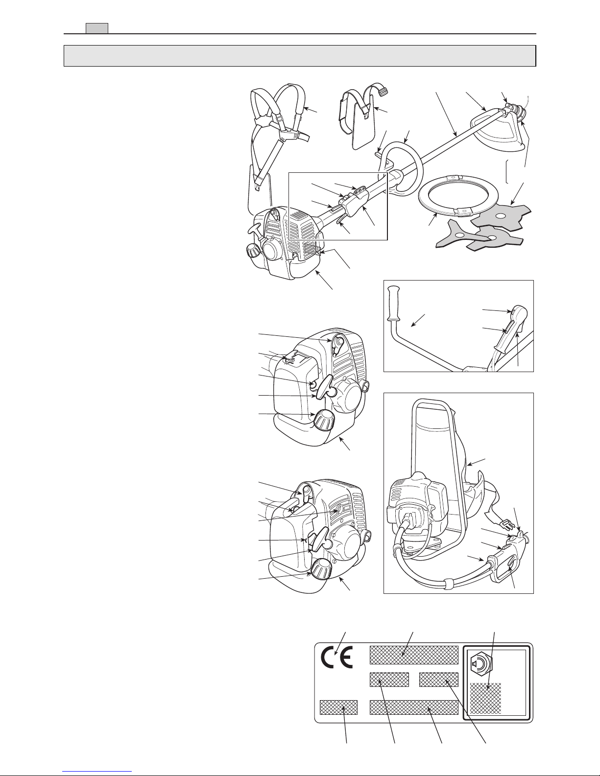
MAIN COMPONENTS
1. Power unit
2. Drive tube
3. Cutting device
a. Blade with 3 or 4 points
b. Cutting line head
4. Cutting device guard
5. Front handgrip
6. Guard
7. Handlebar
8. Rear handgrip
9. Connection point (of the webbing)
10. Identification plate
11. Webbing
a. single belt
b. double belt
c. harness
12. Angle transmission
13. Blade protection (for transport)
14. Spark plug
CONTROLS AND REFUELLING
21. Engine stop switch
22. Throttle trigger
23. Throttle trigger lockout
24. Starter
25. Choke (if present)
26. Primer (if present)
27. Decompression valve (if present)
31. Fuel tank cap
2
IDENTIFICATION OF MAIN COMPONENTS
1. IDENTIFICATION OF MAIN COMPONENTS
IDENTIFICATION PLATE
10.1) Conformity marking in accordance with
Directive 98/37/EC
10.2) Name and address of the manufacturer
10.3) Acoustic output level LWA in accordance
with directive 2000/14/EC
10.4) Manufacturer’s model of reference
10.5) Machine model
10.6) Serial number
10.7) Year of manufacture
10.1
L
WA
dB
10.2
10.6 10.4
10.5
10.7
10.3
14
26
27
25
24
31
1
“DUPLEX”
31D - 36D - 41D - 45DP - 55DP
“MONO” 31 - 36
41 - 45P - 55P
“FLEX” 41F - 45FP - 55FP
31 - 36 - 41
45P - 55P
2
4 12
13
3a
8
6
7
8
9
9
10
11a11b
11c
3b
21
23
22
21
23
22
21
23
22
14
25
26
24
31
1
1
5
3

EN
1) Warning! Danger. The failure to use this
machine correctly can be hazardous for oneself
and others.
2) Read the instruction manual before using the
machine.
3) If you are using the machine every day in normal conditions, you can be exposed to a noise
level of 85 dB (A) or higher.
Wear earmuffs or earplugs and a protective helmet.
4) Wear gloves and protective footwear!
11) Fuel tank
12) Engine stop switch posi-
tions
a = stop
b = run
13) Tuning minimum speed
14) Choke
15) Primer
16) Correct position of the
handgrip on the drive
tube
5) Danger of flying objects! Keep any people or
pets at least 15 m away when using the machine!
6) Do not use the circular saw blade. Danger:
Using the circular saw blade with machines
marked with this symbol exposes the user to
the danger of very serious or even fatal
injuries.
7) Maximum cutting device speed. Only use
suitable cutting devices.
8) Acoustic output level LWA in accordance with
directive 2000/14/EC.
SYMBOLS 3
EXPLANATORY SYMBOLS ON THE
MACHINE (if present)
2. SYMBOLS
7
1 2 3
5 6
4
8
-1
min
ab
11
12
13
14
15
16
21) Cutting device
with adequate
protection
22) To be used with
the cutting line
head
23) Cutting device
rotation direction
EXPLANATORY SYMBOLS ON THE PROTECTION DEVICES (if present)
21
22
23

EN
A) TRAINING
1) Read the instructions carefully. Become
acquainted with the controls and the proper use
of the machine. Learn how to stop the engine
quickly.
2)
Only use the machine for the purpose for
which it was designed,
namely
–
cutting grass and non-woody vegetation,
using a nylon line (e.g. around the edges of
lawns, flowerbeds, walls, fences and small
grassy areas to tidy up the cutting done using a
mower);
–
cutting tall grass, dry branches, twigs and
woody shrubs
of up to 2 cm diameter, with the
help of metal or plastic blades.
Any other use may be dangerous and damage the
machine.
3) Never allow children or persons unfamiliar with
these instructions to use the machine. Local regulations can restrict the age of the user.
4) The machine must never be used by more than
one person.
5)
Never use the machine:
– when people, especially children or pets are in
the vicinity;
– if the user is tired or unwell, or has taken medi-
cine, drugs, alcohol or any substances which
may slow his reflexes and compromise his
judgement;
– if the user is not capable of holding the machine
firmly with two hands and/or remaining stand-
ing on the ground whilst working.
6) Keep in mind that the operator or user is
responsible for accidents or hazards occurring to
other people or their property.
B) PREPARATION
1) Always wear adequate clothing which does not
hamper movements when using the machine.
– Always wear slim-fitting protective clothing, fit-
ted with shear-proof protection devices.
–Always wear a helmet, protective gloves, eye-
goggles, a half-mask respirator and safety anti-
shear boots with non-slip soles.
– Always wear ear and hearing protection
devices.
–Never wear scarves, shirts, necklaces, or any
hanging or flapping accessory that could catch
in the machine or in any objects or materials in
the work area.
–Tie your hair back if it is long.
2)
WARNING: DANGER! Petrol is highly flam-
mable:
– keep the fuel in containers which have been
specifically manufactured and homologated for
such use;
– never smoke when handling fuel;
– slowly open the fuel tank to allow the pressure
inside to decrease gradually;
– top up the tank with fuel in the open air, using a
funnel;
– add fuel before starting the engine. Never
remove the fuel tank cap or add fuel while the
engine is running or when the engine is hot;
– if you have spilt some fuel, do not attempt to
start the engine but move the machine away
from the area of spillage and avoid creating any
source of ignition until the fuel has evaporated
and fuel vapours have dissipated;
– immediately clean up all traces of fuel spilt on
the machine or on the ground;
– never start the machine in the same place you
refilled it with fuel;
– make sure your clothing does not come into
contact with the fuel, on the contrary, change
your clothes before starting the engine;
– always put the tank and fuel container caps
back on and tighten well.
4) Replace faulty or damaged silencers.
5)
Before using the machine, check its general
condition and in particular:
– the throttle trigger and the safety lever must
move freely, they must not need forcing and
should return automatically and rapidly back to
the neutral position;
– the throttle trigger must remain locked until the
safety lever is pressed;
– the engine stop switch must easily move from
one position to the other;
– the electric cables and in particular the spark
plug cable must be in perfect condition to avoid
the generation of any sparks, and the cap must
be correctly fitted on the spark plug;
– the machine handgrips and protection devices
must be clean and dry and well fastened to the
machine;
– the cutting devices and guards must be
undamaged.
6) Check the correct position of the handgrips
and the connection point of the webbing, and the
proper balance of the machine.
7) Before starting work make sure that the guards
are suitable for the cutting tool being used and are
fitted correctly.
8) Thoroughly inspect the whole work area and
remove anything that could be thrown up by the
machine or damage the cutting group or engine
(stones, branches, iron wire, bones, etc.).
C) OPERATION
1) Do not start the engine in a confined space
where dangerous carbon monoxide fumes can
collect.
2) Mow only in daylight or good artificial light.
3)
Take on a firm and well-balanced position:
– where possible, avoid working on wet, slippery
ground or in any case on uneven or steep
4 SAFETY REQUIREMENTS
3. SAFETY REQUIREMENTS

ground that does not guarantee stability for the
operator;
– never run, but walk carefully paying attention to
the lay of the land and any eventual obstacles;
– assess the potential risks of the ground to be
mown and take all necessary precautions to
ensure your own safety, especially on slopes or
on bumpy, slippery or unstable ground;
– work along the contour on slopes, never when
walking up or down and always keep downhill
of the cutter.
4) Make sure the machine is securely locked
when you start the engine:
–start the motor in an area at least 3 metres from
where you refuelled;
– check that there is nobody within at least 15
metres of the machine’s range of action or at
least 30 metres for heavier mowing;
– do not direct the silencer and therefore the
exhaust fumes towards inflammable materials.
5)
Do not change the engine governor settings
or overspeed the engine.
6) Do not strain the machine too much and do not
use a small machine for heavy-duty works. If you
use the right machine, you will reduce the risk of
hazards and improve the quality of your work.
7) Check that when the machine is running idle,
there is no movement of the cutting device and,
after pressing the throttle trigger, the engine
quickly returns to minimum speed.
8) Ensure that the blade does not come into violent contact with foreign bodies and beware of the
possibility of material being thrown up by the
blades.
9) Always keep the machine connected to the
webbing when working.
10)
Stop the engine:
– whenever you leave the machine unattended.
– before refuelling.
– during movements between work areas.
11)
Stop the engine and disconnect the spark
plug cable:
– before cleaning, checking or working on the
machine;
– after striking a foreign object. Inspect the
machine for any damage and make repairs
before restarting it again;
– If the machine starts to vibrate abnormally: find
and remove the cause of the vibration immediately;
– when the machine is not in use.
D) MAINTENANCE AND STORAGE
1) Keep all nuts, bolts and screws tight to be sure
the equipment is in safe working condition.
Routine maintenance is essential for safety
and for maintaining a high performance level.
2) Do not store the machine with fuel in the tank
in an area where the fuel vapours could reach an
open flame, a spark or a strong heat source.
3) Allow the engine to cool before storing in any
enclosure.
4) To reduce fire hazards, keep the engine,
exhaust silencer and fuel storage area free from
sawdust, branches, leaves, or excessive grease;
never leave containers with the cut debris inside
the storage area.
5) If the fuel tank has to be emptied, this should
be done outdoors once the engine has cooled
down.
6) Always wear protective gloves when handling
the cutting device.
7)
For safety reasons, never use the machine
with worn or damaged parts. Damaged parts
are to be replaced and never repaired. Only
use original spare parts.
Parts that are not of the
same quality can seriously damage the equipment
and compromise safety. The cutting tools must
always bear the manufacturer’s trademark as well
as a reference to the maximum working speed.
8) Before putting the machine away, check you
have removed wrenches or tools used for maintenance.
9) Store the machine out of the reach of children!
E) TRANSPORTATION AND HANDLING
1) Whenever the machine is to be handled or
transported you must:
– turn off the engine, wait for the cutting device to
stop and disconnect the spark plug cap;
– fit the cutting device guard;
– only hold the machine using the handgrips and
position the cutting device in the opposite
direction to that used during operation.
2) When using a vehicle to transport the machine,
position it so that it can cause no danger to persons and fasten it firmly in place to avoid it from
tipping over, which may cause damage or fuel
spillage.
F) HOW TO READ THE MANUAL
Certain paragraphs in the manual contain particularly significant information and are marked with
various levels of highlighting with the following
meaning:
or
These give details or further
information on what has already been said, in the
aim to prevent damage to the machine.
Non-observance will result
in the risk of injury to oneself or others.
Non-observance will result
in the risk of serious injury or death to oneself
or others.
!
DANGER!
!
WARNING!
IMPORTANT
NOTE
SAFETY REQUIREMENTS 5
EN

The machine is supplied with
some of the components disassembled and the
fuel tank empty.
Always wear strong work
gloves to handle the cutting devices. Mount
the components very carefully so as not to
impair the safety and efficiency of the
machine. If in doubt, contact your dealer.
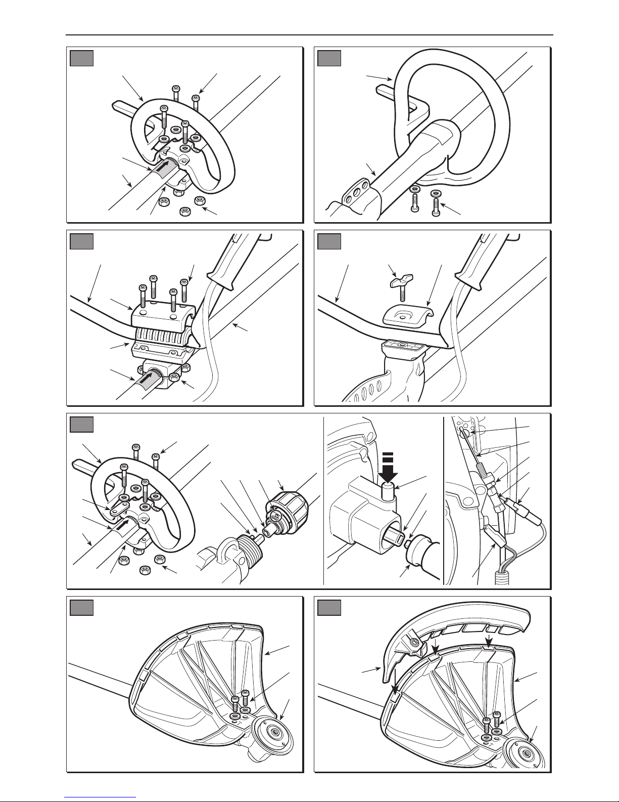
1. COMPLETING THE MACHINE
1a. “MONO” models
• Model 31 (Fig. 1)
– Fit the front handgrip with guard (1) on the
drive tube (2) using the cap (3), screws (4) and
nuts (5) inserted into their specific seatings.
– Before tightening the screws (4), position the
handgrip (1) matching up with the arrow (6) on
the label located on the drive tube.
– Fully tighten the screws (4).
• Models 36 - 41 - 45P - 55P (Fig. 2)
– Fit the front handgrip with guard (1) on the
plastic fairing (2), fully tightening the screws
(3).
1b. “DUPLEX” models
• Model 31D (Fig. 3)
– Put the handlebar (1) with relative rubber
sleeves into the seating in the support (2),
located on the drive tube (3), making sure that
the controls are on the right.
– Fit the cap (4), fully tightening the screws (5)
and nuts (6) inserted in their specific seatings.
– The support (2) is already preassembled on
the drive tube (3) so that the edge matches up
with the arrow (7) on the label; this position
must never be changed.
!
WARNING!
IMPORTANT
• Models 36D - 41D - 45DP - 55DP (Fig. 4)
– Unscrew the central knob (1) and remove the
cap (2).
– Insert the handlebar (3), making sure that the
controls are on the right.
– Set the handlebar in the most comfortable
working position and lock it using the cap (2)
and knob (1).
1c. “FLEX” models
• Models 41F - 45FP - 55FP (Fig. 5)
– Fit the front handgrip with guard (1) on the
drive tube (2) using the cap (3), screws (4) and
nuts (5) inserted in their specific housings,
making sure that the plate (7) under the left
rear screw is in the correct position.
– Before tightening the screws (4), position the
handgrip (1) matching up with the arrow (6) on
the label located on the drive tube.
– Fully tighten the screws (4).
Proceed as follows to connect the flexible tube
to the power unit:
– Insert the end of the shaft (8) into the hub (9)
protruding from the front handgrip, align the
pin (10) with the hole (11) in the drive tube
flange and fully screw in the sleeve (12).
– Insert the end of the shaft (13) into the hub (14)
protruding from the power unit, press the locking button (15) and fully insert the flexible tube
(16) into its seating until the button (15) can be
felt to rise.
– Connect the throttle wires (17) to the carburet-
tor lever (18), making sure that the sheath (19)
is properly inserted into its specific seating
and lock the nut (20).
– Connect the two terminals of the red cables
(21) together and connect the black cable (22)
to the terminal screwed onto the power unit.
2. FITTING THE GUARDS
Each cutting device is provided with a specific guard. Never use guards
other than those indicated for each cutting
device.
!
WARNING!
6 MACHINE ASSEMBLY
EN
4. MACHINE ASSEMBLY

•3 or 4-point blade (Fig. 6)
ear protective gloves and
fit the blade guard.
– Remove the blade (if fitted) as described in
paragraph 3.
– The guard (1) is fixed to the angle transmission
(2) by two screws (3).
• Cutting line head (Fig. 7)
When using the cutting
line head the additional guard, with line cutting knife, must always be fitted.
– Remove the blade (if fitted) as described in
paragraph 3.
– The guard (1) is fixed to the angle transmission
(2) by two screws (3).
– Fit the additional guard (4), inserting the cou-
plers into the respective seatings in the guard
(1) and pressing until a click is heard.
3. REMOVING AND REFITTING THE CUT-
TING DEVICES
Use only original cutting
devices or ones homologated by the
Manufacturer.
•3 or 4-point blade (Fig. 8)
Wear protective gloves and
fit the blade guard.
The cup screw (4) has a lefthand thread and so must be unscrewed in a
clockwise direction and screwed up anticlockwise.
– Insert the wrench supplied (2) into the specific
hole in the angle transmission (3) and rotate
the blade (1) by hand until the wrench enters
the inner hole, blocking rotation.
– Remove the cup (4) unscrewing the central
screw
in a clockwise direction.
– Unthread the outer ring-nut (5) and remove the
blade (1).
NOTE
!
WARNING!
!
WARNING!
!
WARNING!
!
WARNING!
When mounting,
– Ensure that the grooves in the inner ring-nut
(6) match up perfectly with the angle transmis-
sion (3).
– Fit the blade (1) and outer ring-nut (5).
– Refit the cup (4), fully tightening it
in an anti-
clockwise direction
.
– Remove the wrench (2) to restore blade rota-
tion.
• Cutting line head (Fig. 9)
The cutting line head has a
left-hand thread and so must be unscrewed in a
clockwise direction and screwed up anticlockwise.
– Insert the wrench supplied (2) into the specific
hole in the angle transmission (3) and rotate
the cutting line head (1) by hand until the
wrench enters the inner hole, blocking rotation.
– Remove the cutting line head (1) unscrewing it
in a clockwise direction.
When mounting,
– Ensure that the grooves in the inner ring-nut
(6) match up perfectly with the angle tranmission (3).
– Fit the cutting line head (1) screwing it up
in an
anticlockwise direction
.
– Remove the wrench (2) to restore shaft rota-
tion.
• Saw blade (if permitted)
Use of the saw blade is
prohibited on machines marked with the specific symbol (see chap. 2 n° 6).
Follow the instructions supplied with the saw
blade to fit it and its guard.
!
WARNING!
NOTE
MACHINE ASSEMBLY 7
EN

8 PREPARING TO WORK
EN
CHECKING THE MACHINE
Before starting work please:
– check that all the screws on the machine and
the cutting device are tightly fastened;
– check that the cutting device is undamaged
and that the 3 or 4-point metal blades (if fitted)
are properly sharpened;
– check that the air filter is clean;
– check that the protection devices are well fas-
tened and working efficiently;
– check the handgrips are well fastened.
PREPARING THE FUEL
This machine is fitted with a two-stroke engine
which requires a mixture of petrol and lubricating
oil.
Using petrol alone will damage the motor and will cause for invalidation of
the warranty.
Only use quality fuels and
oils to maintain high performance and guarantee
the duration of the mechanical parts over time.
• Petrol characteristics
Only use unleaded petrol with a fuel grade of at
least 90 N.O.
Unleaded petrol tends to
create deposits in the container if preserved for
more than 2 months. Always use fresh petrol!
• Oil characteristics
Only use top quality synthetic oil specifically for
two-stroke engines.
Your dealer can provide you with oils which have
been specifically developed for this type of
engine, and which are capable of guaranteeing a
high level of protection.
The use of these oils makes it possible to prepare a 2% mixture, consisting in 1 part oil to 50
parts petrol.
In the event that no specific oil is available, it is
IMPORTANT
IMPORTANT
IMPORTANT
possible to use a mineral lubricating oil for
engines (class FA or FB), where in this case the
mixture must be 4%, i.e. 1 part oil and 25 parts
petrol.
•Preparation and preservation of the fuel
mixture
Petrol and the fuel mixture are highly inflammable!
– Keep the petrol and fuel mixture in homolo-
gated fuel containers, in safe place, away
from any flames or heat sources.
– Never leave the containers within the reach
of children.
– Never smoke whilst preparing the mixture
and avoid inhaling the petrol fumes.
The chart indicates the amount of petrol and oil
to use to prepare the fuel mixture according to
the type of oil used.
To prepare the fuel mixture:
– Place about half the amount of petrol in a
homologated tank.
– Add all the oil, according to the chart.
– Add the rest of the petrol.
– Close the top and shake well.
The fuel mixture tends to
age. Do not prepare excessive amounts of the
fuel mixture to avoid deposits from forming.
Keep the petrol and fuel mixture containers separate and easily identifiable to
avoid the mistake of using one in place of the
other.
IMPORTANT
IMPORTANT
!
DANGER!
5. PREPARING TO WORK
Petrol Synthetic oil Mineral Oil
2-stroke Class FA - FB
litres litres cm
3
litres cm
3
10.022.0 0.04 40
20.04400.0880
30.06600.12120
50.10100 0.20 200
10 0.20 200 0.40 400

Periodically clean the petrol
and fuel mixture containers to remove any eventual deposits.
REFUELLING
Never smoke whilst refu-
elling and avoid inhaling the petrol fumes.
Carefully open the tank top
as pressure could have formed inside.
Before refuelling:
– Shake the fuel mixture container well.
!
WARNING!
!
DANGER!
IMPORTANT
– Place the machine on a flat stable surface,
with the fuel tank cap facing upwards.
– Clean the fuel tank cap and the surrounding
area to avoid any dirt from entering the tank
during refilling.
– Carefully open the fuel tank cap to allow the
pressure inside to decrease gradually. Use a
funnel to refill and avoid filling the tank to the
brim.
Always close the fuel tank
cap firmly.
Immediately clean all
traces of fuel which may have dripped on the
machine or the ground and do not start the
engine until the petrol fumes have dissipated.
!
WARING!
!
WARNING!
PREPARING TO WORK / HOW TO START - USE – STOP THE ENGINE 9
EN
when it was switched off or after refuelling.
To start the engine (Fig. 10):
1. Set the switch (1) to «START».
2.
If your machine has a decompression
valve, press it now.
3. Operate the starter, turning lever (5) or (5a) to
«CLOSE».
4. Press the primer device button (6) 3 or 4
times to prime the carburettor.
5. Hold the machine firmly on the ground with
one hand on the power unit, in order not to
lose control of the machine during startup
(Fig. 11).
To prevent distortions, the
drive tube must not be used as a support for the
hand or knee during startup.
6. Pull the starter rope slowly for 10 - 15 cm until
IMPORTANT
STARTING THE ENGINE
The engine must be started in an area at least 3 metres from where
you refilled the fuel tank.
Before starting the engine:
– Place the machine firmly on the ground.
– Remove the guard from the blade (if used).
– Make sure the blade (if used) is not touching
the ground or any other object.
• Cold starting
A “cold” start of the engine
means starting it after at least 5 minutes from
NOTE
!
WARNING!
6. HOW TO START - USE – STOP THE ENGINE

EN
10 HOW TO START - USE – STOP THE ENGINE
you feel some resistance, then tug it hard a
few times until you hear the engine turn over.
To avoid breaking the starter
rope, do not pull the whole length of it or let it
slide along the edge of the cable guide hole.
Release the starter gradually, to avoid letting it fly
back uncontrollably.
7. Pull the starter rope again until the engine
starts as normal.
Starting the engine with
the starter engaged causes the cutting
device to move, only stopping when the
starter is disconnected.
8. In models 31 - 36 - 41, when the engine has
started, press the throttle trigger to disconnect the starter and allow the engine to idle.
In models 45P - 55P, the starter is disconnected by turning lever (2a) to «OPEN».
9. Let the engine run idle for at least 1 minute
before using the machine.
If the starter rope is pulled
repeatedly with the choke on, it may flood the
engine and make starting difficult.
If you have flooded the engine, remove the spark
plug and gently pull the handle on the starter
rope to eliminate any excess fuel; then dry the
spark plug electrodes and replace it on the
engine.
• Hot starting
When hot starting (immediately after stopping
the engine), follow the procedure indicated
above in points 1 - 5 - 6 - 7.
USE OF THE ENGINE (Fig. 10)
Cutting device speed is regulated by the throttle
trigger (2), located on the rear handgrip (4) or the
right handgrip (4a) of the handlebar.
The throttle trigger only works if the lockout (3) is
IMPORTANT
!
WARNING!
IMPORTANT
pressed at the same time.
The movement is transmitted from the engine to
the drive shaft by a centrifugal mass clutch that
prevents the shaft from moving when the engine
is running at minimum speed.
Never use the machine if
the cutting device moves when the engine is
running idle; if this is the case regulate the
minimum rate (see chap.8) and if the problem
persists please contact your dealer.
The correct running speed will be achieved by
pressing the throttle trigger (2) as far as possible.
Avoid using the engine at full
power for the first 6-8 working hours.
STOPPING THE ENGINE (Fig. 10)
To stop the engine:
– Release the throttle trigger (2) and allow the
engine to run idle for a few seconds.
– Set the switch (1) to “STOP”.
When you have reduced
speed to a minimum, it will take a few seconds for the cutting device to stop
!
WARNING!
IMPORTANT
!
WARNING!

EN
USING THE MACHINE 11
To respect people and the environment:
– Try not to cause any disturbance.
– Scrupulously comply with local regulations
and provisions for the disposal of waste
materials after sawing.
– Scrupulously comply with local regulations
and provisions for the disposal of oils,
petrol, damaged parts or any elements
which have a strong impact on the environment.
Prolonged exposure to
vibrations can cause injuries and neurovascular disorders (also called “Renaud’s syndrome” or “white hand”), especially to people
suffering from circulation disorders. The
symptoms can regard the hands, wrists and
fingers and are shown through loss of sensitivity, torpor, itching, pain and discolouring of
or structural changes to the skin. These
effects can be worsened by low ambient temperatures and/or by gripping the handgrips
excessively tightly. If the symptoms occur,
the length of time the machine is used must
be reduced and a doctor consulted.
Always wear suitable
clothing when using the machine. Your dealer can provide you with all the information on
the most suitable accident-prevention
devices to guarantee your safety.
USING THE WEBBING (Fig. 12)
The machine must always
be used connected to the webbing worn correctly. Frequently check the efficiency of the
quick release mechanism used to quickly free
the machine from the belts in case of danger.
The webbing must be put on before connecting
the machine to the special coupling and the
belts must be adjusted to suit the operator’s
height and stature.
If the machine has more than one coupling hole,
use the most favourable point for keeping the
machine balanced when working.
!
WARNING!
!
WARNING!
!
WARNING!
Always use webbing suited to the weight of the
machine and the cutting device used
– the single or double belt models can be used
for machines weighing less than 7.5 kg fitted with the cutting line head or 3 or 4-point
blades;
– the double belt model must be used for
machines weighing more than 7.5 kg fitted
with the saw blade
(if permitted).
•
Single belt “MONO” models
The belt (1) must go over the left shoulder
towards the right hip.
• Double belt models
The belt (2) must be worn with:
– the padded part and snap-hook coupling on
the right;
– the release in front;
–the belt cross-over on the operator’s back.
The belts must be tensioned so that the load is
evenly distributed on the shoulders.
•
“FLEX” models
Wear the webbing harness like a normal backpack.
Tension the belts so that the load is evenly distributed on the shoulders, fasten the waist belt
and connect the elastic to the plate.
USING THE MACHINE
When working, the
machine must always be firmly held in both
hands, keeping the power unit on the right of
the body and the cutting group below the line
of the belt.
Stop the engine immediately if the blade stops during sawing. Always
beware of a kickback, which could occur if a
blade encounters a solid object (logs, roots,
branches, stones, etc.). Do not touch the
!
WARNING!
!
WARNING!
7. USING THE MACHINE

EN
12 USING THE MACHINE
ground with the blade. Kickbacks cause
blade recoils that are difficult to control, so as
to cause loss of control of the machine, compromise operator safety and cause damage
to the machine itself.
Before tackling a mowing job for the first time it
is advisable to gain the necessary familiarity with
the machine and the most suitable cutting techniques, finding out how to wear the webbing correctly, firmly gripping the machine and making
the movements required by the job.
•
Choosing the cutting device
Choose the most suitable cutting device for the
job to be done, according to these general indications:
–
the 3-point blade is suitable for cutting
brushwood and small shrubs up to 2 cm in
diameter;
–
the 4-point blade is suitable for cutting resistant grass over large surfaces;
–
the cutting line head can eliminate tall grass
and non-woody vegetation near fences, walls,
foundations, pavements, around trees, etc. or
to completely clean a particular area of the
garden;
–
the saw blade (if permitted) is suitable for cutting resistant bushes, shrubs and small trees
with a trunk up to 6 cm.
WORKING TECHNIQUES
a) 3-point blade (Fig. 13)
Start cutting above the undergrowth and then
move down with the scything blade so as to cut
the brush into small pieces.
b) 4-point blade (Fig. 14)
Proceed using the machine as a traditional
scythe, with a circular movement of about 6090°, thus moving outside the undergrowth, and
so on.
c) Cutting line head
Use ONLY nylon lines. The
!
WARNING!
use of metal lines, plasticised metal lines
and/or lines not suitable for the head can
cause serious injuries and wounds.
During use it is advisable to stop the engine periodically and remove the weeds wound round the
machine, so as to prevent the drive tube from
overheating due to the grass caught under the
guard.
Remove the caught-up grass with a screwdriver
to allow the rod to be properly cooled.
Do not use the machine
for sweeping, tilting the cutting line head.
The power of the engine could throw objects
and small stones 15 metres or more, causing
damage and injuries to people.
• Cutting in motion (Scything) (Fig. 15)
Proceed at a regular pace, with a circular motion
similar to a traditional scythe, without tilting the
cutting line head during the operation.
First try cutting at the right height in a small area,
so as to then achieve a uniform cutting height
keeping the cutting line head at a constant distance from the ground.
For heavier cutting it can be useful to tilt the cutting line head by about 30°.
Do not work in this way if
there is the possibility of causing objects to
be thrown, which could harm people and animals and cause damage.
• Precision cutting (Trimming)
Keep the machine slightly tilted so that the lower
part of the cutting line head does not touch the
ground and the cutting line is at the required
point, always keeping the cutting device at a distance from the operator.
• Cutting near fences/foundations (Fig.16)
Slowly approach the cutting line head to fences,
posts, rocks, walls, etc. without hitting them
hard.
!
WARNING!
!
WARNING!

If the line strikes a solid object it could break or
become worn; if it gets tangled in a fence it
could break abruptly.
In any case, cutting around pavements, foundations, walls, etc. can cause greater wear than
normal in the line.
• Cutting round trees (Fig.17)
Walk round the tree from left to right, approaching the trunks slowly so as not to strike the tree
with the line and keeping the cutting line head
tilted forward slightly.
Remember that the nylon line could lop or damage small shrubs and that the impact of the
nylon line against the trunk of bushes or trees
with soft bark could seriously damage the plant.
•
Adjusting line length when working (Fig. 18)
This machine is fitted with a “Tap & Go” head.
To r elease more line, tap the cutting line head
against the round with the engine at top speed:
the line will be released automatically and the
knife cut off the excess length.
d) Saw blade (if permitted) (Fig. 19)
Use of the saw blade is
prohibited on machines marked with the specific symbol (see chap. 2 n° 6). When using
the saw blade, where permitted, the specific
guard must always be fitted. The blade must
always be well sharpened to reduce the risk
of kickback.
When felling small trees,
estimate the direction in which the cut tree
will fall, also taking the wind direction into
consideration.
To get a good result when felling small trees, the
cut must be made with a rapid movement
towards the branch or trunk to be cut, with the
engine at maximum revs.
!
WARNING!
!
WARNING!
Do not use the right-hand area of the blade
because there is a high risk of kickback or the
blade seizing up, due to the direction of rotation.
END OF OPERATIONS
When you have finished your work:
– Switch off the engine as indicated above
(Chap. 6).
–Wait for the cutting device to stop and fit the
blade guard (if 3 or 4-point blades of saw
blades are used).
USING THE MACHINE 13
EN

Correct maintenance is essential to maintain the
original efficiency and safety of the machine over
time.
During maintenance operations:
– Remove the spark plug cap.
–Wait until the engine is sufficiently cold.
– Use protective gloves when handling the
blades.
– Keep the blade protection device on,
except when intervening directly on the
blade.
– Never dispose of oils, fuel or other polluting
materials in unauthorised places.
CYLINDER AND SILENCER
To reduce fire risks, periodically clean the cylinder flaps with compressed air and clear the
silencer area to get rid of sawdust, branches,
leaves or other debris.
STARTING SYSTEM
To avoid overheating and damage to the engine,
always keep the cooling air vents clean and free
of sawdust and debris.
The starter rope must be replaced as soon as it
shows signs of wear.
NUTS AND SCREWS
Periodically check that all the nuts and screws
are securely tightened and the handgrips are
tightly fastened.
CLEANING THE AIR FILTER (Fig. 20)
Cleaning the air filter is
essential to guarantee the efficiency and duration
of the machine. Do not work with a damaged filter or without a filter, as this could permanently
damage the engine.
It must be cleaned after every 8-10 working
hours.
Clean the filter as follows:
– Remove the cover (1) and filter element (2) by
pressing the tongue (3).
IMPORTANT
!
WARNING!
–Wash the filter element(2) with soap and water.
Do not use petrol or other solvents.
– Leave the filter to dry in the open air.
– Fit the filter element (2) and the cover (1) back
on.
CHECKING THE SPARK PLUG (Fig. 21)
Periodically remove and clean the spark plug
using a metal brush to get rid of any deposits.
Check and reset the correct distance between
the electrodes.
Replace the spark plug and fasten it firmly using
the supplied wrench.
The spark plug must be replaced with one with
the same characteristics whenever the electrodes have burnt or the insulation has worn, and
in any case every 100 working hours.
TUNING THE CARBURETTOR
The carburettor is tuned by the manufacturer to
achieve maximum performance in all situations,
with a minimum emission of toxic gas in compliance with the regulations in force.
In the case of poor performance contact your
Dealer for a check of the carburetion and engine.
•
Tuning minimum speed
The minimum speed must
only be tuned if the cutting device moves
when the engine idles.
Speed is reduced by turning the screw marked
«MIN» anti-clockwise until the cutting device
stops moving. The engine should continue to run
as normal.
If the engine does not idle smoothly, turn the
screw clockwise to increase the speed.
The cutting device must
not move when the engine idles; contact your
dealer if you are not able to tune it to your
satisfaction.
!
WARNING!
!
WARNING!
14 MAINTENANCE AND STORAGE
EN
8. MAINTENANCE AND STORAGE

ANGLE TRANSMISSION (Fig. 22)
Lubricate with lithium-based grease.
Remove the screw (1) and put in the grease,
turning the shaft manually until grease emerges,
then replace the screw (1).
SHARPENING THE 3 OR 4-POINT BLADE
(Fig. 23)
Use protective gloves. If
sharpening is done without removing the
blade, disconnect the spark plug cap.
Sharpening must be done taking account of the
type of blade and cutting edges, using a flat file
and working all the points equally.
The references for correct sharpening are given
in Fig. 23:
A = Incorrect sharpening
B = Sharpening limits
C = Incorrect and unequal angles
It is important to retain the correct balance after
sharpening.
3 or 4-point blades can be used from both sides.
When one side of the points is worn, the blade
can be turned and the other side used.
The blade must never be
repaired, but must be replaced as soon as
signs of breaking are noted or the sharpening
limit is exceeded.
HEAD LINE REPLACEMENT
Follow the instructions attached to the head for
replacing the nylon line.
SHARPENING THE LINE CUTTING KNIFE
(Fig. 24)
– Remove the line cutting knife (1) from the
guard (2) by unscrewing screw (3).
– Fix the line cutting knife in a vice and sharpen
it using a flat file, being careful to retain the
original cutting angle.
– Refit the knife on the guard.
!
WARNING!
!
WARNING!
SHARPENING THE 24-TOOTH SAW BLADE
(Fig. 25)
Use protective gloves. If
sharpening is done without removing the
blade, disconnect the spark plug cap.
Check that the blade set is approximately 1 mm
and, if necessary, adjust it with pliers.
Sharpen all the teeth uniformly using a round file
(1) 5.5 mm in diameter, using it as shown in the
figure and working alternately on the left and
right teeth.
The tooth profile must not be changed.
The saw blade is not
reversible, thus it must only be used from one
side.
The blade must never be repaired, but must be
replaced as soon as signs of breaking are noted
or the sharpening limit is exceeded.
EXTRAORDINARY MAINTENANCE
All maintenance operations not foreseen in this
manual must be performed exclusively by your
dealer.
All and any operations performed in unauthorised centres or by unqualified persons will totally invalidate the warranty.
STORAGE
After every work stint, clean the machine thoroughly to remove all dust and debris, and repair
or replace any faulty parts.
The machine must be stored in a dry place away
from the elements and with the cover correctly
fitted.
!
WARNING!
!
WARNING!
MAINTENANCE AND STORAGE
15
EN

LONG PERIODS OF DISUSE
If you are not going to use
the machine for a period of more than 2-3
months, we recommend you do a few things
before putting it away. This will make it easier
when you want to use the machine again and will
also prevent permanent damage to the engine.
• Storage
Before putting the machine away:
– Empty the fuel tank.
– Start the engine and run it idle until it comes to
a halt, so that it uses up all the fuel that is left
in the carburettor.
–Wait for the engine to cool down and remove
the spark plug
IMPORTANT
– Pour a teaspoon of fresh oil into the spark plug
hole.
– Pull the starter rope several times to deliver oil
to the cylinder.
– Replace the spark plug with the piston in the
dead end upper position (visible from the
spark plug slot when the piston is at maximum
stroke).
• Restarting work
When you wish to start using the machine again:
– Remove the spark plug.
– Pull the starter rope a few times to eliminate
excess oil.
– Check the spark plug as described in chapter
“Checking the spark plug”.
–Prepare the machine as indicated in the para-
graph entitled “Preparing for work”.
16
MAINTENANCE AND STORAGE / TROUBLESHOOTING
EN
9. TROUBLESHOOTING
1) The engine will
not start or will not
keep running
2) The engine starts
but is lacking in
power
3) The engine runs
irregularly and lacks
in power when
revved
4) The engine gives
off an excessive
amount of smoke
– Incorrect starting procedure
– Dirty spark plug or incorrect distance
between the electrodes
– Air filter clogged
– Carburetion problems
– Air filter clogged
– Carburetion problems
– Dirty spark plug or incorrect distance
between the electrodes
– Carburetion problems
– Incorrect composition of the fuel
mixture
– Carburetion problems
– Follow the instructions (see chap-
ter 6)
– Check the spark plug (see chapter
8)
– Clean and/or replace the filter (see
chapter 8)
– Contact your dealer
– Clean and/or replace the filter (see
chapter 8)
– Contact your dealer
– Check the spark plug (see chapter
8)
– Contact your dealer
–Prepare the fuel mixture according
to the instructions (see chap. 5)
– Contact your dealer
PROBLEM LIKELY CAUSE SOLUTION

Engine .................................. 2-stroke air-cooled
Capacity / Power
Mod. 31 - 31D ..................... 27.8 cm
3
/ 1.1 kW
Mod. 36 - 36D ..................... 32.5 cm
3
/ 1.3 kW
Mod. 41 - 41D - 41F............ 36.3 cm
3
/ 1.5 kW
Mod. 45P - 45DP - 45FP..... 44.3 cm
3
/ 1.9 kW
Mod. 55P - 55DP - 55FP..... 50.8 cm
3
/ 2.1 kW
Engine rotation speed at tick-over
Mod. 31.. - 36.. - 41.. .............. 2500-2900 rpm
Mod. 45.. - 55.. ....................... 2400-2700 rpm
Maximum engine rotation speed
Mod. 31.. - 36.. - 41.. .......... 10000-11000 rpm
Mod. 45.. - 55.. ..................... 9500-10000 rpm
Maximum tool rotation speed
Mod. 31.. .......................................... 8000 rpm
Mod. 36.. - 41 - 41D ........................ 8500 rpm
Mod. 41F ............................................... 7000 v
Mod. 45P .......................................... 8500 rpm
Mod. 45DP - 45FP ........................... 7400 rpm
Mod. 55P .......................................... 8900 rpm
Mod. 55DP - 55FP ........................... 7400 rpm
Spark plug.... RCJ 7 Y Champion (or equivalent)
Mixture .......... Petrol : 2-stroke oil = 50:1 = 2%
Tank capacity
Mod. 31... .......................................... 700 cm
3
Mod. 36... - 41... ............................... 1000 cm
3
Mod. 45... - 55... ............................... 1300 cm
3
Maximum permitted blade diameter
3-point blade ................................. Ø 255 mm
4-point blade ................................. Ø 255 mm
Saw blade
“MONO” (excluding Mod. 31) and
“DUPLEX” ..................................... Ø 255 mm
“FLEX” models .............................. Ø 225 mm
Weight
1)
“MONO” models ................. from 5.7 to 6.1 kg
“DUPLEX” models .............. from 6.8 to 8.7 kg
“FLEX” models ................ from 10.7 to 11.9 kg
1)
Weight as per standard ISO 11806 (without
fuel, cutting devices and guards)
TECHNICAL SPECIFICATIONS 17
EN
10. TECHNICAL SPECIFICATIONS
Phonometric Recordings and Vibrations
Model............................................. 31 31D 36 36D 41 41D 41F 45P 45DP 45FP 55P 55DP 55FP
Noise level recorded (ISO 10884) dB(A)
with line cutter head .................... 107,0 107,3 109,0 109,0 108,8 108,8 108,8 111,5 111,5 111,5 110,8 110,8 110,8
with 4-point blade........................ 105,0 105,0 106,2 106,2 106,0 106,0 106,0 107,8 107,8 107,8 107,5 107,5 107,5
Noise level at the operator’s ear (EN 27917) dB(A)
with line cutter head .................... 98,1 92,2 98,7 98,5 99,6 98,6 98,2 99,1 98,8 98,8 99,3 99,1 98,9
with 4-point blade ....................... 96,1 95,1 97,3 95,2 97,6 93,5 92,2 98,2 96,6 93,7 98,6 96,9 94,2
Vibrations transmitted to the hand on the front handgrip (“MONO” and “FLEX”) (ISO 7916) m/sec
2
at tick-over .................................. 4,5 – 1,9 – 3,4 – 1,3 1,8 – 0,4 3,7 – 0,5
with line cutter head ................... 4,4 – 1,0 – 2,9 – 3,1 2,8 – 2,8 4,2 – 2,5
with 4-point blade ....................... 5,8 – 2,1 – 4,0 – 2,6 3,9 – 3,3 3,9 – 3,1
Vibrations transmitted to the hand on the rear handgrip (“MONO” and “FLEX”) (ISO 7916) m/sec
2
at tick-over ................................. 3,1 – 2,3 – 2,1 – 1,4 4,0 – 0,3 2,7 – 0,8
with line cutter head ................... 5,2 – 2,5 – 3,4 – 2,6 3,1 – 2,6 3,0 – 2,5
with 4-point blade ....................... 6,9 – 3,5 – 3,7 – 2,4 3,8 – 3,3 3,5 – 3,1
Vibrations transmitted to the hand on the left handgrip (“DUPLEX”) (ISO 7916) m/sec
2
at tick-over ................................. – 2,6 – 2,7 – 2,7 – – 2,0 – – 2,6 –
with line cutter head ................... – 3,3 – 2,4 – 3,0 – – 1,5 – – 2,1 –
with 4-point blade ....................... – 5,2 – 3,0 – 1,9 – – 2,3 – – 2,3 –
Vibrations transmitted to the hand on the right handgrip (“DUPLEX”) (ISO 7916) m/sec
2
at tick-over ................................. – 3,7 – 3,5 – 2,9 – – 2,6 – – 2,9 –
with line cutter head ................... – 3,2 – 2,8 – 4,5 – – 1,4 – – 1,8 –
with 4-point blade ....................... – 4,7 – 3,6 – 1,8 – – 1,8 – – 1,7 –

18
 Loading...