

Page 1
Worldwide Manufacturer of Gas Detection Solutions
Remote Control
RC2
Operations Manual
1194 Oak Valley Dr, Ste 20, Ann Arbor MI 48108 USA
(800) 959-0329 • (734) 769-0573 • www.goodforgas.com
Page 2

Page 3

Table of Contents
For your safety …………………………………………………………………………. 2
Operational hints ………………………………………………………………………. 2
General description ……………………………………………………………………. 2
Operation ……………………………………………………………………………….. 4
Trouble shooting ……………………………………………………………………….. 4
Replacement of battery ……………………………………………………………….. 5
Signal transmission ……………………………………………………………………. 5
Technical data …………………………………………………………………………. 5
EC-Type Examination Certificate ……………………………………………………. 6
Page 4
For your Safety
Do NOT replace the battery of the remote control in potentially explosive areas.
6LR61 /
MN1604, the plastic bottoms of which prevent the leaking of electrolyte.
2
As with any piece of complex equipment, the GfG RC2 will do the job it is designed to do only
if it is used and serviced in accordance with the manufacturer's instructions. Please protect
yourself and your employees by following the instructions in this manual. All individuals who
have or will have the responsibility for using and servicing this product must carefully read this
manual. The warranties made by GfG with respect to the product are voided if functions or
parameters are changed without the permission of GfG. They are also voided if the product is
not used and serviced in accordance with the instructions in this manual. The above does not
alter any statements by GfG regarding warranties, conditions of sale and/or delivery.
Operational Hints
The remote control RC2 is connected to a GfG transmitter by a connection cable and is used
for operating the transmitter or as a display. When connected to a GfG transmitter it provides
a display and a keypad, the readout and the keypad functions of the remote control are
identical with those of the GfG transmitter.
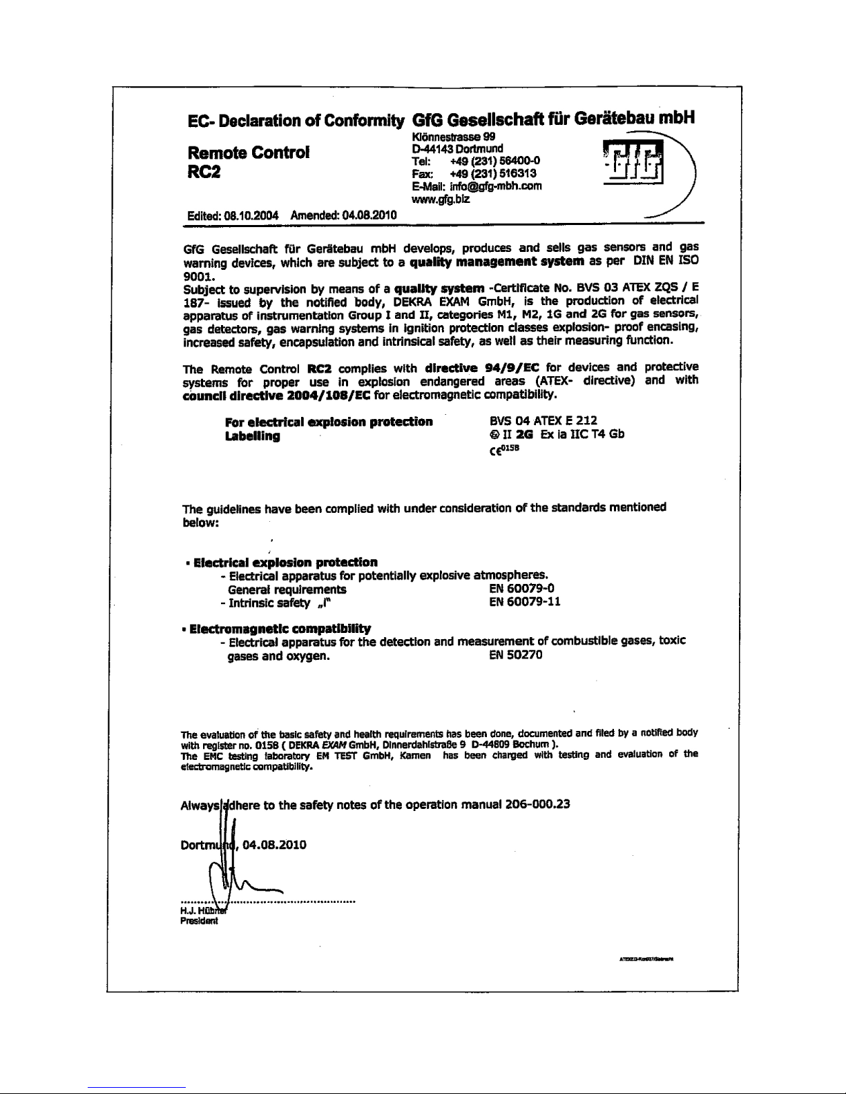
The remote control RC2 is approved for use in explosive areas and is subject to an EC-Type
examination Certificate issued by DEKRA EXAM GmbH, according to directive 94/9/EG (ATEX
100a).
Certificate: BVS 04 ATEX E 212
Labeling: II 2G Ex ia IIC T4 Gb -20°C≤Ta≤+50°C
The remote control may be connected to or disconnected from the transmitter even in an
explosive area.
Only use 9V block batteries type DURACELL-PROCELL Alkaline,
General Description
The Remote Control RC2 is used for control or adjustment of the zeropoint and sensitivity
when testing the transmitter.
Should the Series 28 transmitters be mounted in hard to access locations (i.e. close to the
ceiling) you may, even in explosive areas, keep the cable procured permanently for connecting
the remote control to the transmitter (maximum cable length is 10m / 33 feet). You can
connect this cable to the remote control for display or service purposes.
The maximum cable length between transmitter and remote control is 10m / 33
feet. Only use cables approved by GfG Instrumentation, Inc.
Page 5
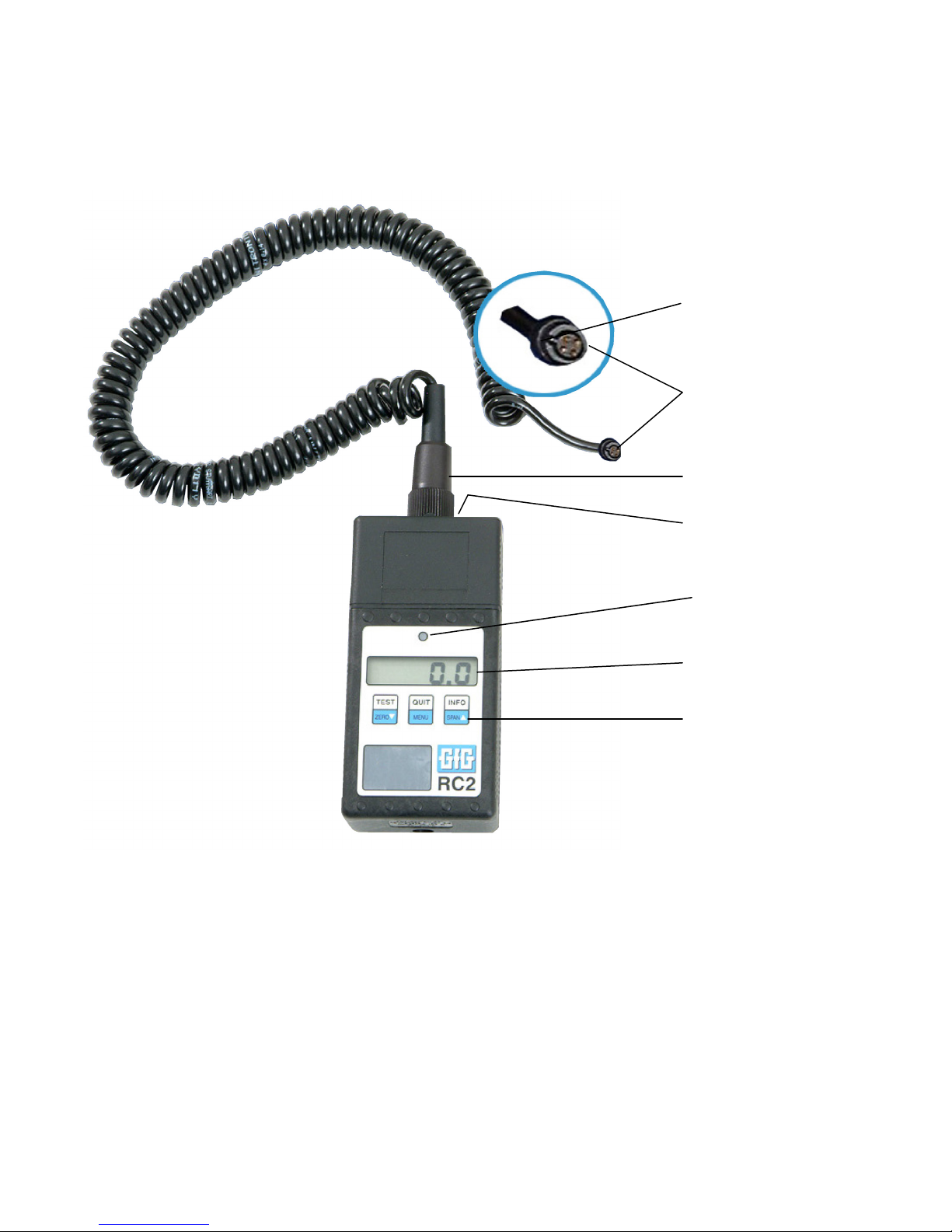
The remote control RC2 is supplied with a helix cable for connection to GfG transmitters. On
Nose of plug
Plug A
Plug B
On/Off Switch
Operational LED
(green)
Display
Keypad
3
one end of the cable is plug A (see figure 1), which plugs into the socket on the transmitter.
The other end of the cable is connected to the remote control and locked in place by slightly
turning the sleeve ring of the plug (plug B).
Fig. 1
The On/Off switch for the remote is located at the top of the case near the plug connection.
When the unit is turned on, the green operational LED above the display is illuminated.
The keypad functions and the display of the remote control RC2 are absolutely identical with
those of the transmitter.
Page 6
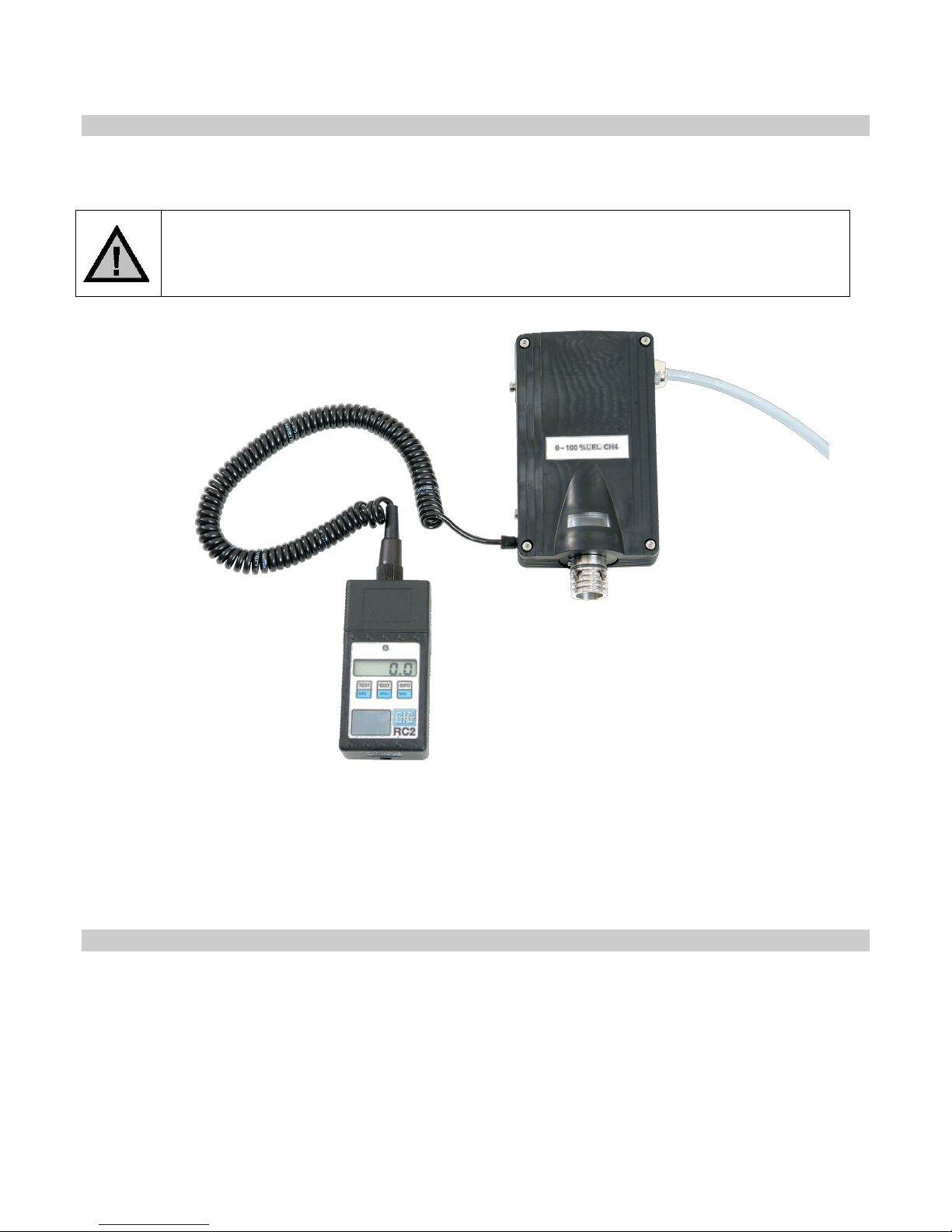
For servicing a GfG transmitter without display, the remote control RC2 is
The remote control RC2 is allowed to be used in explosive areas.
4
Operation
The function of the keypad in the different operational and special modes are described in
detail in the operations manual of the relevant transmitter.
required.
For connection to a GfG transmitter fix plug A (see figure 1, page 3) into the transmitter. If the
plug is connected incorrectly, regardless of the transmitter polarity protection (nose at plug A),
the display at the remote control drops out after a few seconds and will not function.
When the unit is turned on, the green operations LED must be on.
Trouble shooting
If the operational LED does not light up, either replace the battery or check to ensure the
battery is inserted correctly (check for correct polarity).
If the display of the remote control does not show a reading when it is connected to the
transmitter, although the operational LED is on, either the connection is wrong (check plug) or
one of the units, either the transmitter of remote control, is faulty.
Page 7
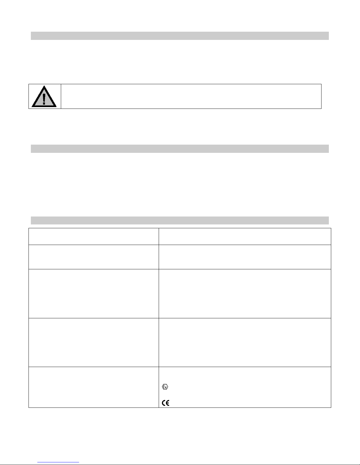
Replacement of battery
Do not replace the battery of the remote control in a potentially explosive area.
Use only 9V batteries type DURACELL-PROCELL Alkaline, 6LR61 / MN1604.
Maximum output voltage
Uo
6 V DC
Maximum output current
Io
45 mA
Maximum output power
Po
68 m W
Maximum output capacity
Co
10 µF
Maximum output inductivity
Lo
1 mH
Remote Control RC2
For connection to transmitter:
Series 28 transmitters
Current Supply
MN1604
Climate Conditions
Atmospheric pressure range:
800 to 1100 hPa
Enclosure
Maximum cable length 10m / 33 feet
Approvals and Certifications
Production monitoring:
0158 (by notified body – DEKRA EXAM GmbH)
5
Remove the two Allen screws on the top then slide the top upward, being careful of the
position of the loose insulating plate. Then slide the front part (with display and keypad) a
slight amount upward and lift it off. The printed circuit board and the battery holder are affixed
to the front part by means of short cables.
When replacing the 9V battery be cautious of the correct polarity (+ and – are indicated on the
holder). After turning the unit on, the green operational LED lights up. If there is incorrect
polarity of the battery, the unit cannot be turned on (the green LED does not light up).
Signal Transmission
The signal from the transmitter to remote control is an intrinsically safe transmission. Both the
transmitter and the cable of the remote control RC2 ensure the compliance of the following
values:
Technical Data
Battery Type: 9 V battery DURACELL-PROCELL Alkaline, 6LR61 /
Short-term storage temperature:
Recommended storage temperature:
Operational temperature (ambient):
Humidity range:
Casing material:
Dimensions:
Protection:
Cable connection to transmitter:
Electromagnetic compatibility:
Labeling and Ignition protection:
EC-Type Examination Certificate:
-25 to +60°C
0 to +30°C
-20 to +50°C
5 to 90% r.h.
Compound, anti-static
60 x 120 x 35 mm / 2.4 x 4.7 x 1.4 inches (W x H x
D) (H with plug: 180mm / 7 inches)
IP 54
DIN EN 50270:2006 Type class I and Type class 2
II 2G Ex ia IIC T4 Gb -20°C≤Ta≤+50°C
BVS 04 ATEX E 212
Page 8
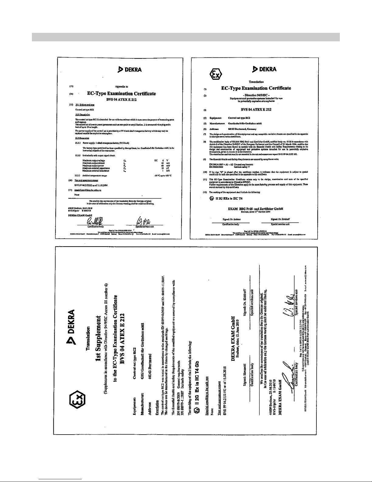
EC-Type Examination Certificate
6
Page 9
7
Page 10

Page 11

Page 12

7004-RC2 Rev. 2 (01/17/18)
GfG Instrumentation, Inc.
USA
Worldwide Manufacturer of Gas Detection Solutions
GfG reserves the right to change part numbers,
1194 Oak Valley Dr.
Suite 20
Ann Arbor, MI 48108
US/Canada: (800) 959-0329
US/Canada Fax: (734) 769-1888
International: +1 734 769 0573
International Fax: +1 734 769 1888
E-mail: [email protected]
Website: www.goodforgas.com
prices, and/or technical information without notification.
 Loading...