

Page 1
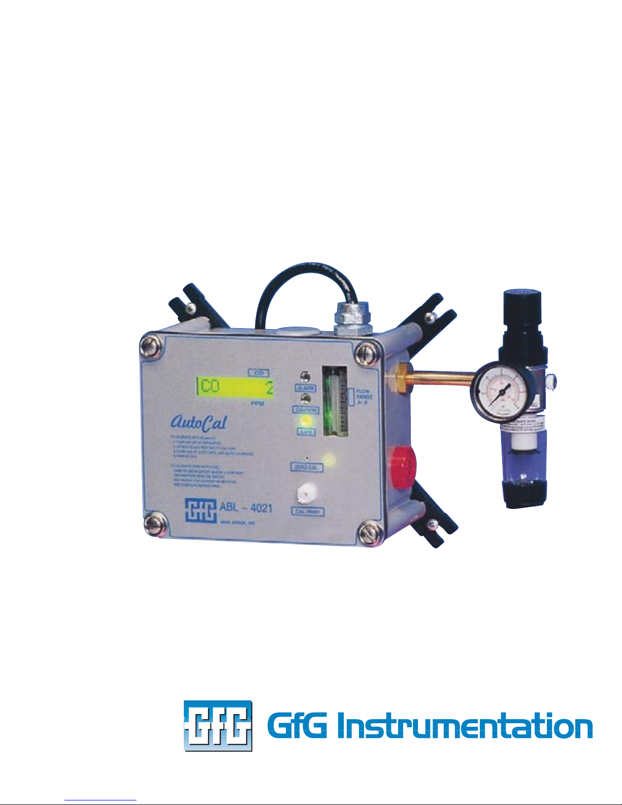
RAM 4021
Andersen Medical Gas
12 Place Lafifitte
Madisonville, LA 70447
https://www.TheMedicalGas.com
1-866-288-3783
Operation Manual
Worldwide Manufacturer of Gas Detection Solutions
Page 2

Page 3

TABLE OF CONTENTS
RAM 4021
For your safety..........................................................................3
Description .................................................................................3
Set-up mode ...........................................................................4
Annunciator lights/alarms.....................................................4
Operation ....................................................................................5
Calibration ..................................................................................6
Calibrating carbon monoxide sensor with CO test gas.....6
“ZERO/CAL” adjustment for carbon monoxide ...................7
Maintenance...............................................................................9
Carbon monoxide sensor replacement ..............................9
Trouble shooting section .....................................................10
Zero fail during CO calibration ...........................................11
Calibration gas fail during CO calibration .........................11
Accessories and field replacement parts ........................12
Replacement parts ....................................................................12
Equipment technical data ....................................................13
Warranty ...................................................................................14
Notes: .........................................................................................17
Page 4

For your safety
Like any piece of complex equipment, the GfG
Instrumentation RAM-4021 will do the job it was designed
to do, only if it is used and serviced in accordance with the
manufacturer’s instructions. All individuals who have or will
have the responsibility of servicing the equipment must
carefully read this manual.
The warranties made by GfG Instrumentation with regards
to this instrument are voided, if the product is not used
and serviced in accordance with the instructions in this
manual. Please protect yourself and others who depend on
this instrument by following these instructions. The above
does not alter statements regarding GfG Instrumentation’s
warranties and conditions of sale and delivery.
Description
General
This unit is designed to provide continuous monitoring of
the carbon monoxide levels of breathing air.
The instrument’s electronics are enclosed in a NEMA-4X
polycarbonate case. The case is corrosion resistant,
positively pressurized by the compressor supply line, and
sealed except for a bleed hole to exhaust the compressor’s
air. The unit operates on 110V AC power. It comes equipped
with a case mounted horn that may be disconnected if not
required.
Calibration adjustment controls are not necessary since
they are automatically performed by the microprocessor.
The carbon monoxide chemical cell has a life expectancy of
two to three years with a 30-day calibration check
recommended.
3
Page 5

Set-up mode
By briefly depressing the bottom button it is possible to
cycle through the set up parameters. Each time the
bottom button is depressed the display screen will identify
the selected mode and indicate the current set up.
The following outlines the set up modes and options
available. In each mode it is possible to change the set up
using the top button.
Annunciator lights/alarms
YelLxx.x – Caution alarm for low flow or first CO alarm
(warn)
CO Alm - XX
-The alarm point in parts per million is displayed. (i.e. CO
ALM 10).
Cal
-The part per million of carbon monoxide to be used for
calibration is displayed (i.e. CO - 20).
NOTE: This set-up must be identical to the ppm
concentration of the carbon monoxide
calibration gas (5 - 100 PPM CO).
The carbon monoxide test gas concentration may be set
from 5 to 100 ppm and is factory set to 20 ppm. It is
important to use the same test gas as the “CAL” setting,
otherwise the calibration will fail because of the error
protection feature.
Changing the calibration gas concentration to another
value without calibrating will fault (FLT) the unit’s reading.
4
Page 6

The FLT message may be removed by returning to the
calibration value prior to changing or calibrating with the
new test gas concentration.
CO # RLY
-The carbon monoxide alarm relay can be made
operational (ON) or disabled (OFF) in this mode. The top
button will change this option.
Setting the relay ON or OFF permits any auxiliary device
connected to them to be shut off if not needed. During
calibration it will be automatically shut off.
Test mode Activates alarm, relays, LEDs, and solid squares
on LED readout when top button is pushed.
The alarm horn and relays may be tested by pressing and
holding the top button while in alarm test Set-Up mode.
When testing an auxiliary horn, be sure the relay is turned
ON.
Operation
Plug the unit into 110V AC and the display will show
introductory messages and a warm-up countdown. If the
unit does not power up, check the electrical connections
and try re-plugging the unit. If the start up does not occur,
call the factory.
After the warm-up countdown, the instrument will display
CO readings. The air regulator may be adjusted at any time
to set the flow level from 0.5 to 0.9 CFH. If the low flow
indication shows on the display, increase the flow to 1 CFH;
and then drop the flow to the operational range of .5 to .8
CFH.
5
Page 7

CAUTION: If the unit is reading a carbon monoxide gas
level, do not make any adjustment for a few
hours until the unit has settled in. If calibration is
attempted within the first fifteen minutes, a TOO
SOON message will occur on the display.
If the carbon monoxide gas readings remain high or below
zero (-0), recalibration may be needed. We also recommend
checking the compressor’s air intake, which may be the
cause for high readings. Outside air intake is recommended
- but can easily be contaminated by furnace exhaust,
building vents, parking lots, etc. Intakes within the building
are to be avoided because they often contain low ppm
levels of carbon monoxide.
Calibration
Calibrating carbon monoxide sensor with CO test gas
(recommended every 30 days)
Although the unit was calibrated at the factory, it may
require carbon monoxide recalibration due to handling.
The only way to assure the sensor is operating properly is
to place gas on it.
To calibrate the unit with carbon monoxide test gas, shut
off the air from the compressor supply line with the
regulator and a LOW FLOW message will appear. Assemble
the calibration kit and connect the tank of test gas to the
calibration port connector on the instrument. Open the gas
valve (use only the fixed flow regulator provided with the
calibration kit). The display will read “CAL GAS” and a 60
second count down will begin.
If the compressor air supply line was not shut off, a
message will appear SUPPLY OFF. If such a message occurs,
6
Page 8

shut off the supply air; and then begin the calibration
process again to activate the calibration port switch.
After 60 seconds a gas reading will appear along with a
count number. With 20 ppm test gas applied the gas
reading should be 20 and the count 70. At 70 counts with
20 ppm CO the unit will automatically set.
The count number is also used for troubleshooting (see
troubleshooting section). After the unit auto calibrates, a
message will appear CO G SET indicating that the CO gain
adjustment has been set for 20 ppm. Next an informational
message on the automatic control pot value is displayed
which also can be used in troubleshooting.
If an incorrect gas concentration is used or the sensor
and/or instrument is not properly functioning, a message
will appear CO G FAILED, PREV CAL, END CAL. This affords
improper calibration protection and an effort should be
made to understand why it did not calibrate (see
troubleshooting section for assistance).
After proper calibration the next messages will be REMOVE
CALIBRATION GAS, END CAL, SUPPLY ON. This prompts the
calibrator to remove test gas and turn the supply on at the
regulator.
“ZERO/CAL” adjustment for carbon monoxide
The carbon monoxide read-out (ppm) will be “0” in the
absence of carbon monoxide. This “0” can be calibrated by
flowing clean air over the sensor and activating the
ZERO/CAL set switch.
7
Page 9

The “ZERO/CAL” set switch is activated through a small hole
in the face of the unit using a wire activator (bent paper
clip).
Two methods are available to check or set the carbon
monoxide ZERO/CAL.
With normal flow through the unit from a clean air supply
depress the ZERO/CAL switch and hold closed until the
carbon monoxide read-out stops flashing (about 3 seconds)
and immediately release the switch.
The auto zero process will begin immediately. If the supply
air is clean the display will indicate CO SET, END
CALIBRATION which indicates that a zero setting has been
accepted and is now in use. If the supply line has more than
a trace of carbon monoxide the following messages will
appear BAD O AIR, PREV CAL, END CAL. The instrument is
informing the user that it will not zero calibrate because of
bad zero air and it will use its previously zeroed calibration
setting.
A second method for zeroing is to place zero test gas
(impurity free air) in the calibration port in the same
manner described previously with calibration gas, and the
unit will initiate its calibration gas routine. However, the
unit expects that 20 ppm CO is being applied in the
calibration port unless
the zero set switch is pushed. Check
to see that the message now says zero gas instead of
calibration gas as the 60 second countdown proceeds. At
any time during the countdown the zero may be pushed to
program the unit for zero gas. If the set switch is not
pushed, a calibration failed message will appear resulting in
returning to the previous calibration. This is the error
8
Page 10

protection. After the zero button is depressed, a ZEROING
message appears and then RELEASE UNLESS ZERO INIT
message.
Holding the zero button for 15 seconds will reinitialize a
unit, which is used when replacing a sensor or as discussed
in the troubleshooting section. Do not ZERO INIT unless
instructed to in the troubleshooting section.
Maintenance (qualified technicians only)
NOTE: Except for the sensors, all internal parts are to
be serviced only by the factory or its
authorized agents.
Carbon monoxide sensor replacement
When CO test gas fails to show a gas response during
calibration, a new sensor is required. Most CO sensors will
last from one and one-half years to three years.
To replace the sensor, disconnect the power to the unit,
remove the four corner screws, and the electronics front
cover. Next remove the three screws that hold the sensor
block and unplug the CO sensor from its socket. Replace
with a new sensor after being sure that the shorting
wire is removed from the new sensor. Reassemble the
unit and reconnect to power. Let the new sensor settle in
for an hour prior to calibrating.
A NEW SENSOR MUST BE INITIALIZED
When calibrating a new sensor, an initializing
step is added
to the procedure. This permits the sensor to be zero /
calibrated regardless of the background air and caution
needs to be taken that the air is free of carbon monoxide.
9
Page 11

If the supply line is not CO free, then obtain a tank of
impurity free air test gas from GfG (stock number 7802-006).
1. To initialize the unit hold the ZERO/CAL set switch
depressed for 15 seconds. (airline OFF) During the
fifteen seconds the messages will read: ZERO CAL,
RELEASE UNLESS ZERO INT, INIT-ING. Release the zero
set switch when INIT-ING appears and the display will
read: ZERO GAS REQUIRED.
Flow air from either the supply line or calibration port and
the unit will set its ZERO/CAL after 60 seconds. The
instrument message will then read CAL GAS REQUIRED.
Supply 20 ppm calibration gas (or another value selected in
the set up mode on the unit) until display reads END CAL,
REMOVE GAS, SUPPLY ON. After turning the air supply on,
the unit will reset the error protection and monitor the
carbon monoxide of the compressor air supply line.
Trouble shooting section
Count numbers
Another set of numbers are displayed during CO calibration
other than the gas concentration. These numbers are there
to assist in trouble shooting in case zero or calibration fails
or other malfunctions occur. These other numbers are
called counts.
The CO zero calibration will not set if the counts are less
than 46 or greater than 53; and when the unit sets at zero,
the number will read 50 r1 counts. With 20 ppm CO
calibration gas the count number will be 70 r1 to set. If the
computer cannot auto adjust the readout to these values
of 50 and 70, the zero or calibration will fail.
10
Page 12

Zero fail during CO calibration
If a failure occurs during CO zero calibration, it means the
counts are not between 46 and 53. If the counts are above
53, a BAD AIR message occurs and the zero air should be
questioned for CO content. When the count level is below
46, it may be a malfunctioning unit or during initial zero
calibration (without the error protection) it was zeroed
with a contaminated gas sample.
Another initialization will remove the 46 to 53 count
restraint, and with known zero air the unit may be rezeroed. If the counts never reach 50, the unit is
malfunctioning, call the factory for further instructions.
Calibration gas fail during CO calibration
With 20 CO ppm gas on the unit the reading should reach
70 counts. If the reading does not reach 70 counts, use the
appropriate following procedure.
1. If the counts or gas reading do not show any increase
when the gas is applied, probably the sensor is expired
or the test gas is zero concentration. Check hose
connections to assure gas is flowing into the sensor
chamber.
2. If the counts are close to 70, a zero reinitializing with
known zero gas will probably correct the problem. If
the unit was initialized with more than a couple ppm
of CO, the calibration will fail when 20 ppm test gas is
applied.
CAUTION: Be sure that the cylinder in use is “zero gas”
impurity free air (standard air) when zero
initializing.
11
Page 13

Accessories and field replacement parts
Accessories
7750-001 Calibration kit (Includes calibration
connector and 20 ppm test gas 34L)
2605-002 High pressure regulator (5000 PSI)
1301-002 Remote horn – 110V AC
Replacement parts
5503-020 CO sensor – chemical cell
2608-004 Regulator
TEST GAS
7802-001 20 ppm carbon monoxide 34L
7802-006 Impurity free air 34L
12
Page 14

Equipment technical data
Gases detected Carbon monoxide
Sensor Electro- chemical cell
Meter scale 0…100 ppm CO
Response 90% maximum in 20 sec
Accuracy expected sensor life +/- 1 ppm, 2-3 years
Sensor warranty’s 1 year
Operating temperature range
+32 qF to 105 qF
(sample air)
Factory set adjustable alarm
points
5 ppm CO (Y)
10 ppm CO (H)
Standard inlet pressure ½” feed – 80 to 120 psig
Sample flow rate 0.5 cubic feet of air per hour (scfh)
Relays
1 – Caution alarm
250V AC/30V DC @ 7 A
1 – CO alarm
Power source 110V AC @ 1 A or 12V DC
Dimensions 7.3 x 5.9 x 4 inches (L x W x H)
(185 x 150 x 101 mm)
13
Page 15

Warranty
GfG INSTRUMENTATION, INC., warrants each new electrical
product manufactured by it to be free from defective
material and workmanship for the purpose intended, for a
period of one (1) year from the date of sale to the original
purchaser, and agrees to remedy any such defect or to
furnish a new part (at the company’s option) in exchange
for any part of any product of its manufacture which
under normal use, and service disclosed such defect;
provided the product is delivered by the purchaser to GfG’s
factory, intact, for our examination, with all transportation
prepaid to our factory, provided that such examination
discloses, in our judgment, that it is thus defective.
This warranty does not extend to any products that have
been subjected to misuse, neglect, accident, unauthorized
modifications, or to use in violation of instructions
furnished by us, nor does it extend to products that have
been repaired or altered outside of our factory. This
warranty is in lieu of all warranties express or implied
and no representative or person is authorized to
assume for us any other liability in connection with
the sale of our products. All implied warranties are
limited to the duration of this written warranty. In no
event is GfG INSTRUMENTATION, INC., liable for special,
incidental, or consequential damages arising from any
breach of warranty of product.
14
Page 16
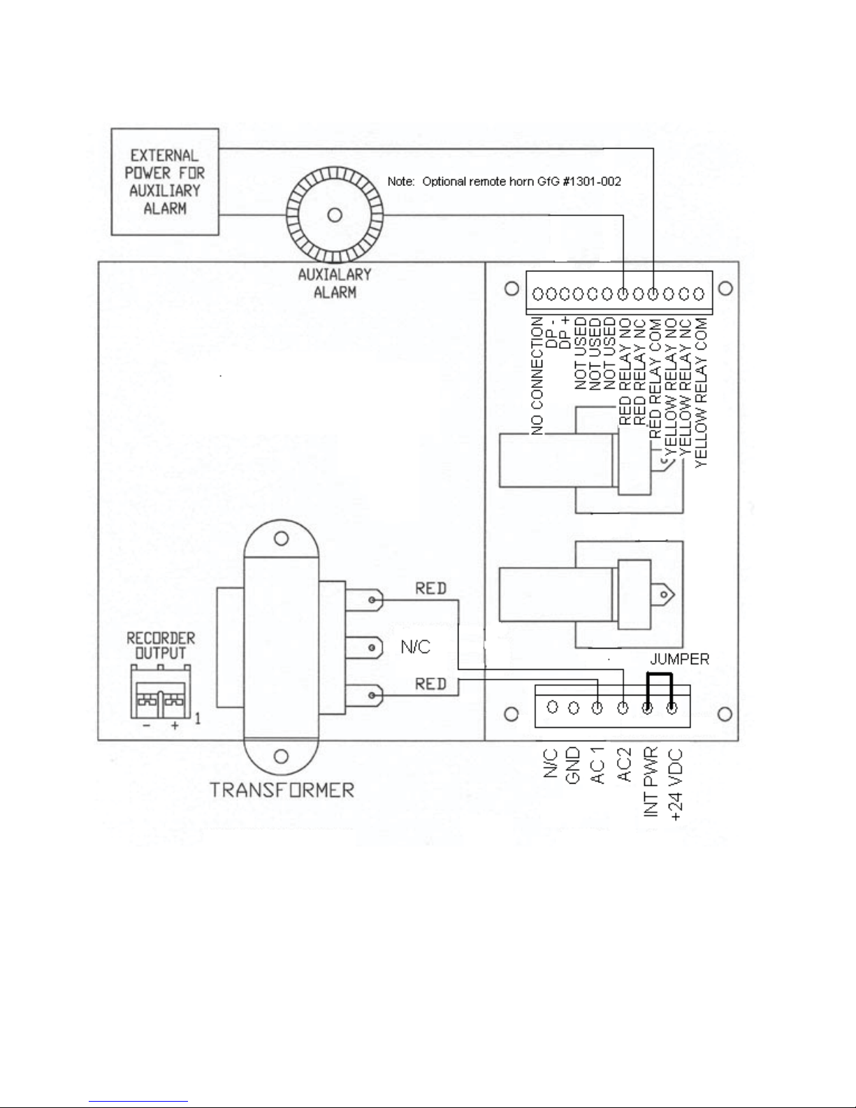
New style
NOTE: Optional GfG remote horn part number 1301-002
15
Page 17
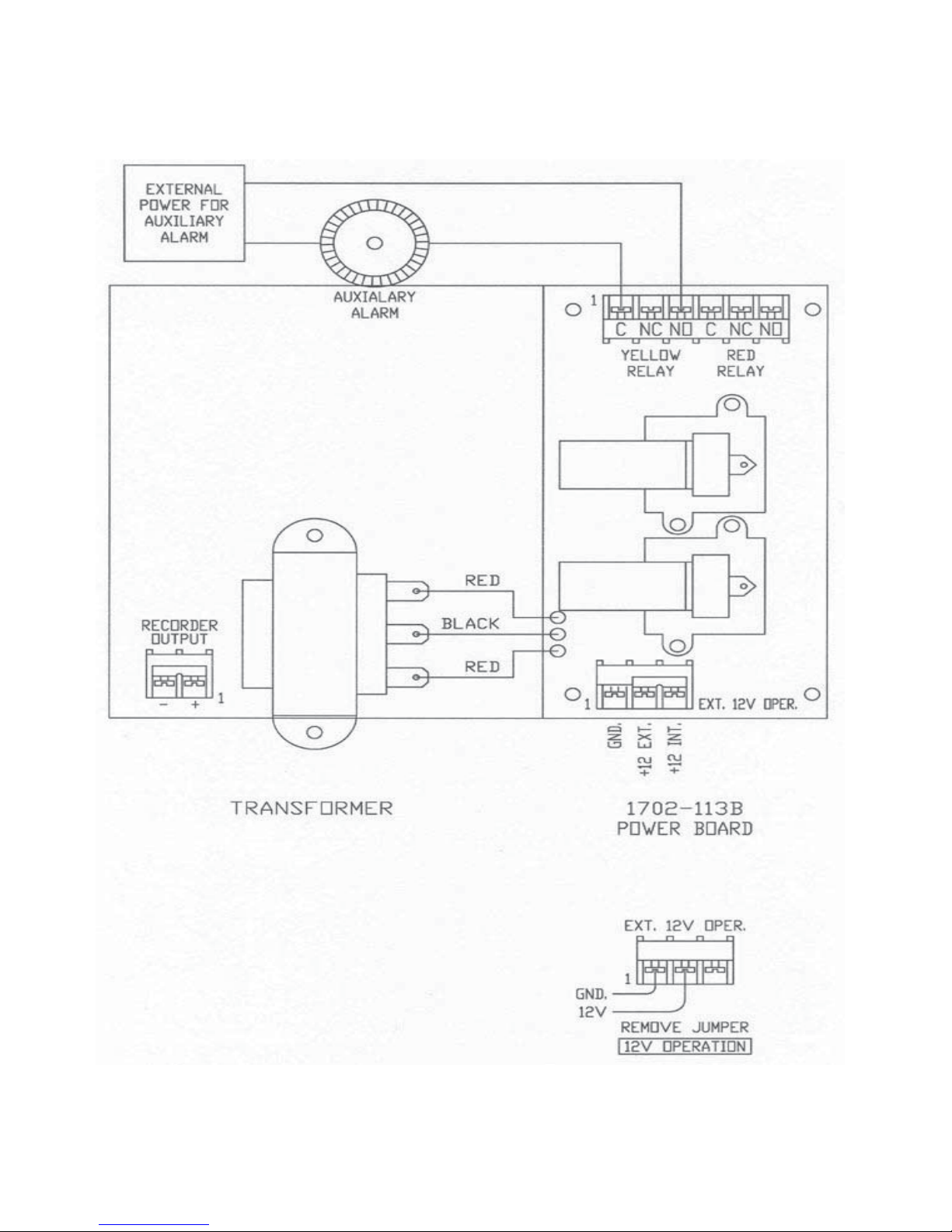
Old style
16
Page 18

Notes:
17
Page 19

Page 20

æ/AKæ6ALLEYæ$RIVEæ3UITEæ
!NNæ!RBORæ-ICHIGANææ 53!
4ELææ
%MAILæINFO GFGINCCOM
7EBæWWWGFGINCCOM
6ISITæOURæNEWæWEBæSITEæATæ
WWWGFGINCCOM
ææ
 Loading...