

Page 1
GfG GESELLSCHAFT FÜR GERÄTEBAU MBH▐ KLÖNNEST RASSE 99▐ D-44143 DORTMUND▐ TELEPHONE +49 / (0) 2 31 / 5 64 00 –0 ▐ FAX +49 / (0) 2 31 / 51 63 13
[email protected] ▐ WWW.GASDETECTION.BIZ▐ AMTSGERICHT DORTMUND HR B 2742▐ CERTIFIED AS PER DIN EN ISO 9001:2000▐ ATEX QM CERTIFICATE
Operation Manual
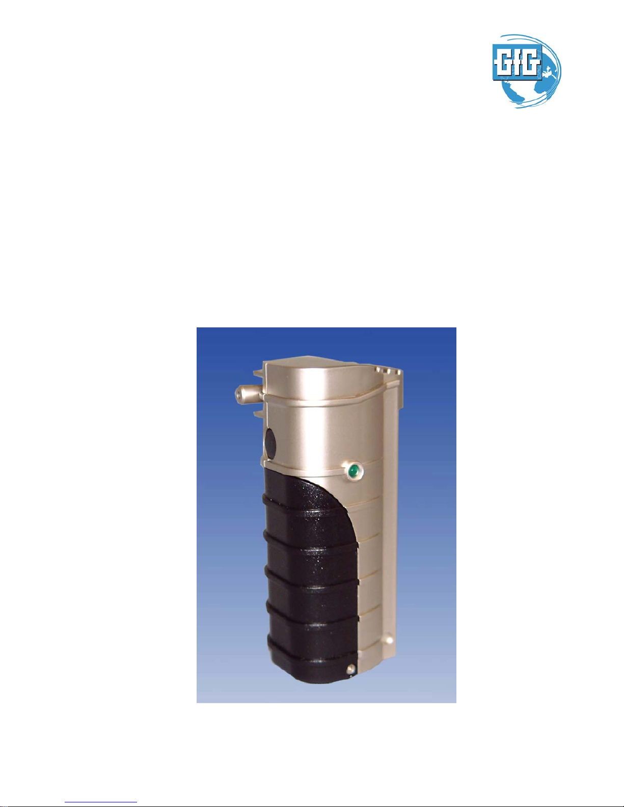
MICRO III/IV – Pump
Pump for G200-Series
Page 2

Content
Introduction 3
For your Safety 3
Application and Use 3
General description and Design 3
Operational Note 4
General hints 4
Turning On 4
Turning Off 4
Confidence signal 4
Flow alarm 4
Battery capacity 5
Test of battery capacity 5
Changing of battery 5
Processor fault 6
Annex 6
Cleaning 6
Maintenance and repair 6
Service and Inspection 6
Spare parts and accessories 6
Technical Data 7
EC-Type Examination Certificate 8
Page 3
Introduction
For your Safety
According to § 3 of the law about technical working media, this manual points out the proper use of the
product and serves to prevent dangers. All individuals who have or will have the responsibility for using and
servicing this product must carefully read this manual. This product will do the job designed to do, only, if it
is used, serviced, maintained and controlled in accordance with the manufacturer's instructions. If not used
properly the warranty of the product is voided. Adjustments in the service mode must be done by experts only.
Before operating the unit, check the battery status and the readiness for operation by means of the
confidence signal.
The above does not alter statements regarding GfG's warranties and conditions of sale and delivery.
Application and Use
Together with the MICRO III or the Micro IV detector the MICRO III-pump is designed for personal safety
under atmospheric conditions. The pump samples the gas by means of an intake towards the sensor. For this
purpose a hose gets attached to the intake, whose ending reaches into the room that needs to be monitored
(e.g. sewer). The MICRO III-pump warns the user by means of a visible alarm if the amount of the sampled
gas is insufficient (flow alarm) or if an internal fault occurs.
General descri pt ion and Design
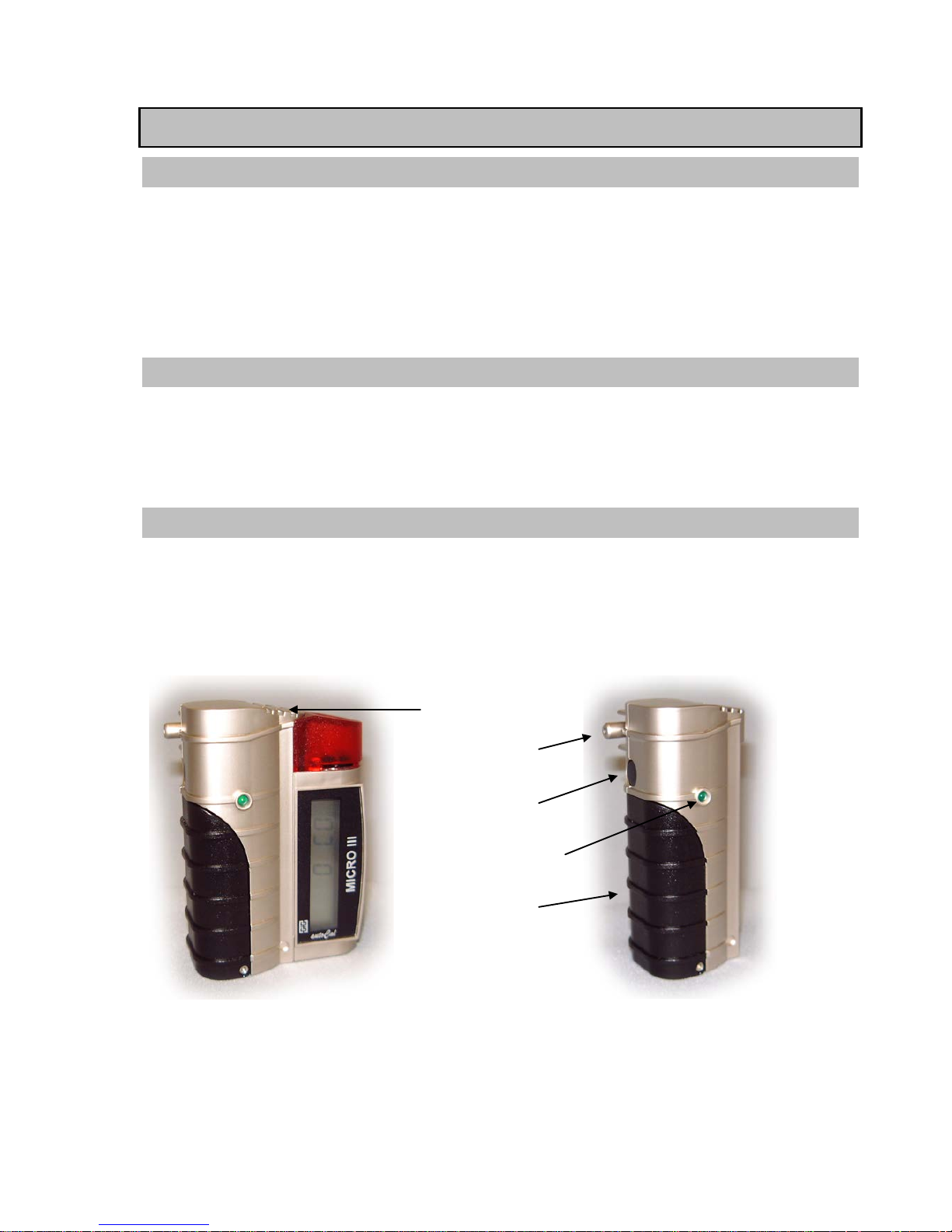
The MICRO III–pump is a very small and handy complementary module for the MICRO III / IV and gets
attached to the MICRO III / IV so that the two units form a whole. For this purpose just slide off the battery
cover of the MICRO III / IV and slide the pump on. The pump allows testing for gases without being exposed
to this atmosphere.
Diffusion inlet
Intake
On/Off button
Operation status-LED
Batteries
Page 4
Operational Note
General hints
• Attention! Airstreams can cause measurement faults. The air that enters the detector by the diffusion
inlet can distort the concentration of the sampled gas. To avoid such an inflow of air, please cover the
diffusion inlet with your hand. Make sure that diffusion inlet is not completely closed to avoid a
pressure increase inside the sensor.
•
For sampling gases out of sewers, rooms or drains a hose (with or without telescopic probe) can be
used that is plugged on the intake. As the response time heavily depends on the inside volume of the
intake appliance the lengths of the appliance shall be as short as possible. For the minimum pump
time (T
min
in seconds) please adhere to the following calculation:
T
min
= 20s + 3s/m*L
hose
+ T
Tele
L
hose
= lengths of hose in meter
T
Tele
= 10s with telescopic probe, 0s without
Turning On
Turn On
Press button On/Off
If the battery capacity is sufficient the MICRO III–pump switches on the pump motor and displays the battery
capacity (see test of battery capacity).
During the normal pump operation an optical confidence sign is displayed to signalize the user that the pump
operates properly (see chapter confidence sign al) .
Turning Off
After the measurement the pump should be turned off to avoid discharging of battery.
Turn Off
Press On/Off button
The MICRO III-pump turns off the pump motor, no further display occurs.
Confidence si gn al
During pump operation the LED is permanently lid. This shows the user that the MICRO III-pump operates
properly.
Flow alarm
If the sampled gas amount is too low or if the power supply of the pump motor is interrupted an optical alarm
is given.
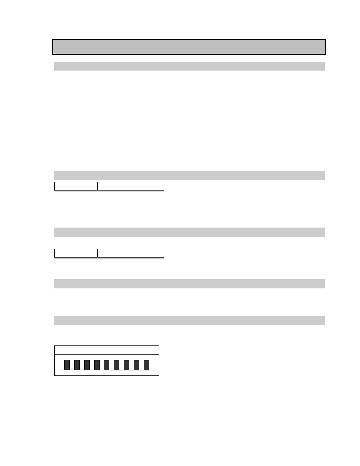
Flow alarm signal
approximately 5 LED-pulses per second
Solution: Way of gas is blocked. Remove cause.
Attention: During flowalarm a proper detection mode in connection with Micro III /IV can not be ensured.
Page 5
Battery capacity
The MICRO III-pump is powered by two 1.5 V AA alkaline batteries (mignon). These batteries allow a
continuous operation of up to 8 hours. The operational time may be reduced by increased load of the pump
motor (e.g. through bended sample hose).
The correct battery types are: DURACELL PROCELL MN 1500 LR6 AA or
INDUSTRIAL
BY
DURACELL ID1500 AA (LR6).
The pump automatically turns off, if the battery voltage falls below the minimum level needed for proper
functioning.
Test of battery capacity
Activation of battery
test
• Turn pump on (press button)
The battery capacity is indicated by a multi-signal
1 2 3 4 5
Empty full
Number of pulse
-signals
Battery capacity
After indication of the battery capacity the LED stays dark for 2 seconds. Herewith the battery test is
completed.
Changing of battery
These batteries must always be purchased from GfG as the manufacturer of the Micro III / IV. In-house QC
makes sure that only batteries are used, which comply with the EC-Type Examination Certificate.
Use only DURACELL PROCELL MN1500 LR6 AA or
INDUSTRIAL
BY
DURACELL ID1500 AA (LR6)!
Note
The batterys must be inserted or replaced in safe areas only. Take care of the correct polarity when
fitting the battery (indicated inside of the battery compartment). With incorrect polarity the pump
motor operates, but the monitoring functions (LED) are turned off.
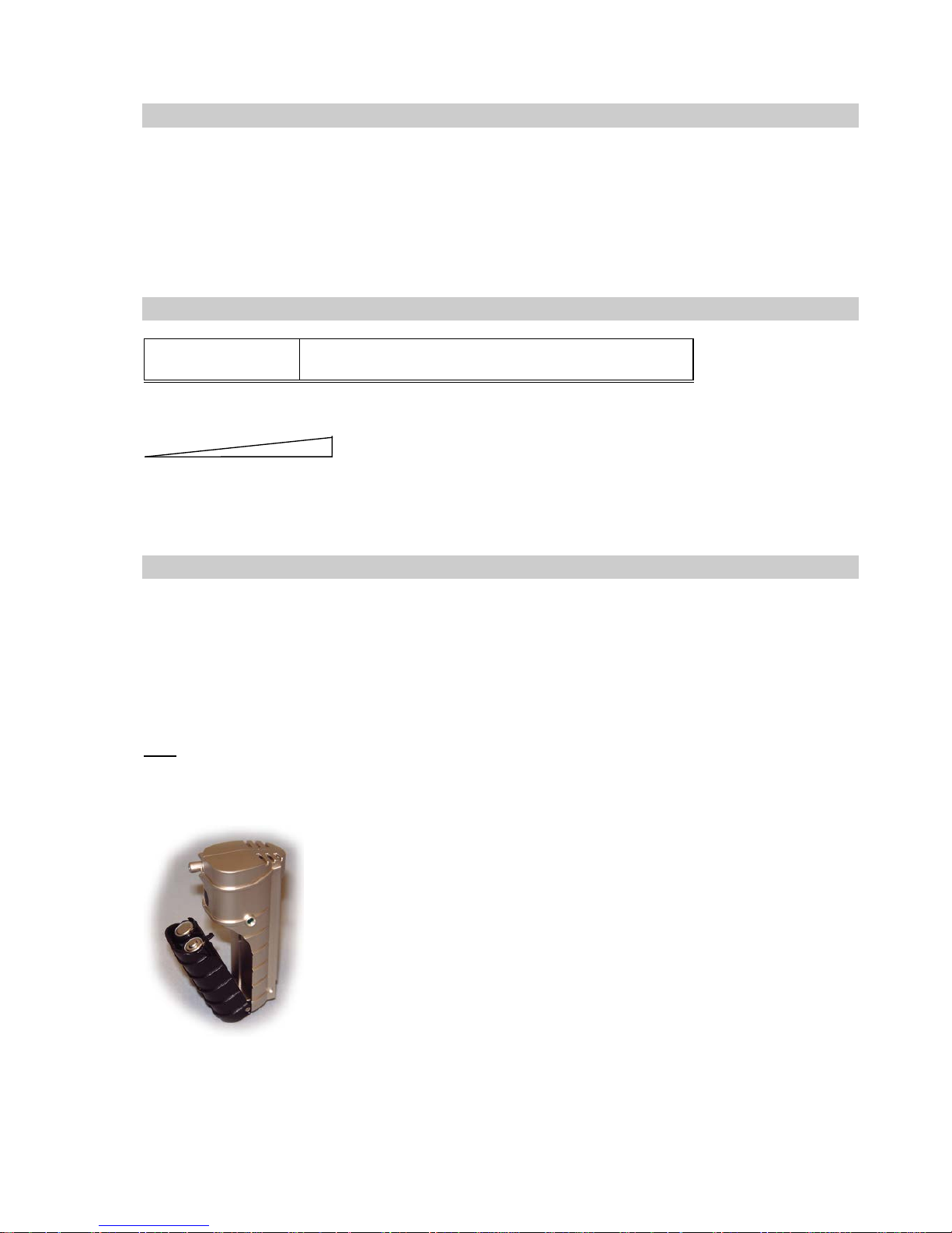
For battery replacement separate the pump froma the Micro III / IV
(slide upwards). Inside the pump cover is a release button for the battery
compartment. The battery cover can then be folded back, the old
batteries can be taken out and new ones can be placed into the battery
compartment.
Note:
• Batteries must not be replaced in hazardous areas!
• Watch out for the correct polarity of the new batteries!
(see pictogramm inside the battery compartement)
Pumpengehäuse
Page 6
Processor f ault
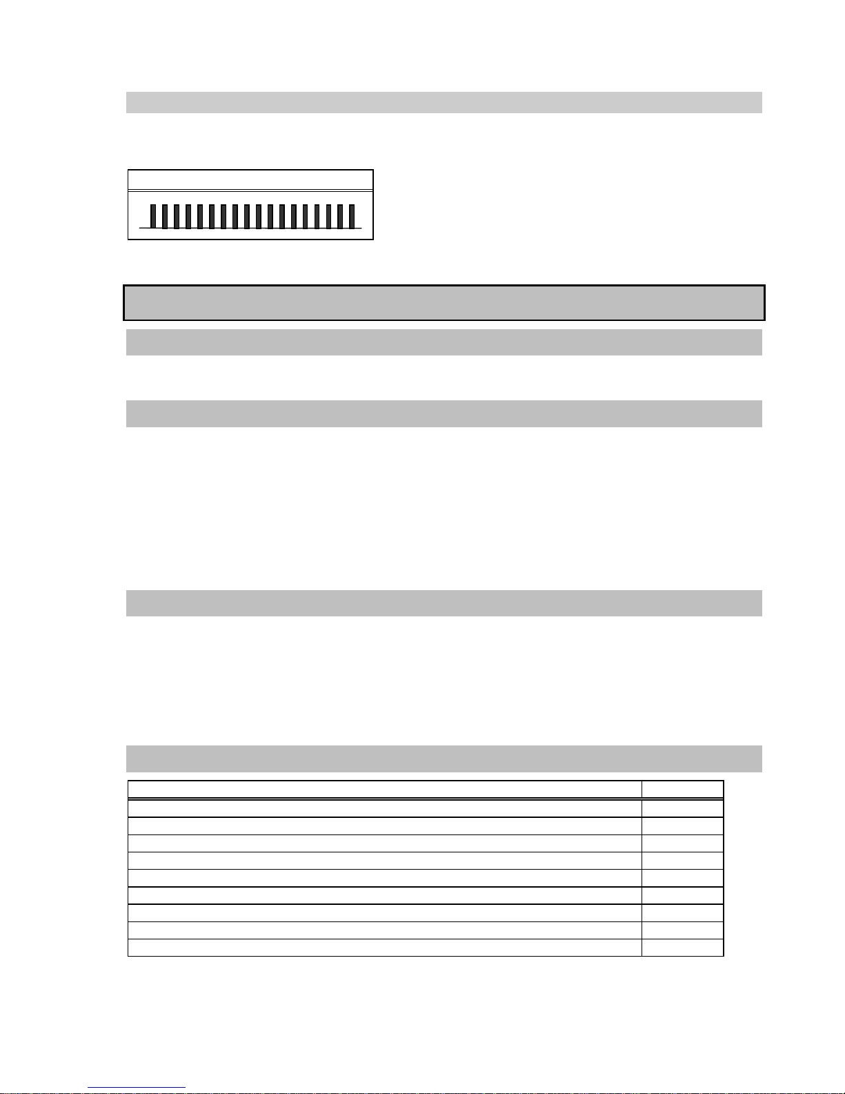
The unit continuously checks its processor. If a fault is recognized a visual alarm is given.
Solution: Change battery, if fault is not solved, send unit to the manufacturer.
Processor fault
Approx. 10 LED-pulses per second
Annex
Cleaning
Give the MICRO III-pump a short sight check after use. Use a damp cloth to re move stains or soiling from the
casing. Never use solvents or cleaning agents!
Maintenance and repair
A function test should be carried out at least once a year and contain :
• the charge status of the battery
• sight check
• check of sampling performance
The test has to be carried out by an expert and a writt en confirmation must be filed. In case of repairs, only
genuine spare parts are to be used, and the manufacturer’s instructions have to be adhered to.
Service and Inspec t ion
Maintenance and inspection describe those measures, which retain the nominal status of the MICRO IIIpump. The functioning of the unit has to be checked. Make sure the MICRO III-pump passes a test before it is
being used. This test should control the following:
• the charge status of the battery
• the activation of the flow alarm (e.g. by blocking the inlet). The pump should give a flow alarm warning.
Spare parts and accessories
Description
Part-No.
Alkaline Battery INDUSTRIAL BY DURACELL ID1500 AA (LR6)
1318201
Battery compartment with release button
1318340
AQUA-SHIELD splash water protection, 15 units
1318205
Telescopic probe CrNi-steel 1,36m
1000205
Special dust/water filter, pack of 3
1000207
Special sampling hose 3m, anti static, with dust/water filter
1000208
Special sampling hose 3m, anti static, with dust/water filter and flow indicator
1000209
Viton hose, solvent resistant, for H2S, fuel vapors etc.
1000217
Float probe
On request
Page 7
Technical Data
Type:
MICRO III – pump
Display:
green LED
Pump performance:
0.50 l/min for 0 mm Wc
0.40 l/min for 300 mm Wc
Alarms:
Visual battery alarm,
visual flow alarm for falling below min. flow or hardware fault (interrupt)
Gas supply:
Inlet for pump operation, otherwise diffusion
Climate conditions:
for operation:
-20...+55 (45)°C
for storage:
-25...+55°C (recommended 0...+30°C)
Power supply:
2 batteries mignon type AA 1.5 V / Duracell Procell MN 1500 LR6 AA or
INDUSTRIAL BY DURACELL ID1500 AA (LR6)
Operational time:
Readiness for operation:
up to 8 hours continuous operation (depending on load)
up to 2 years if turned off
Casing:
Material:
Polycarbonate, metalised
Dimensions:
43 x 92 x 32 mm (WxHxD)
Weight:
97 g
Protection:
IP40
Approval:
Electromagnetic Compatibility:
as per EN50270 type 2 and EN55022 Class B
Labelling and ignition protectio n: only when used with Duracell Procell MN 1500 LR6 AA or
INDUSTRIAL BY DURACELL ID1500 AA (LR6)
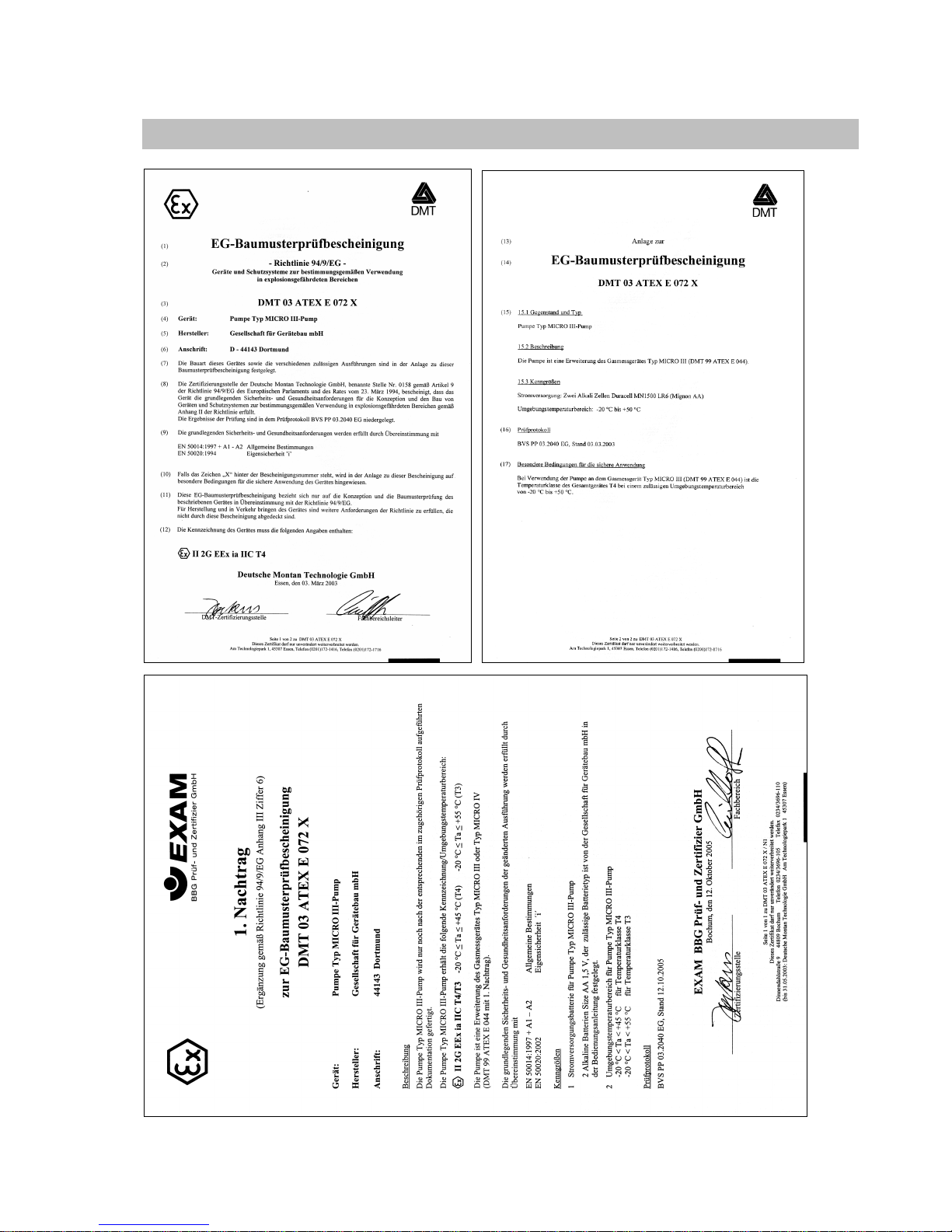
II 2G EEx ia IIC T4 resp. T3 -20°C ≤ Ta ≤ +45°C resp. +55°C
EC type approval:
DMT 03 ATEX E 072 X
Production supervision:
0158 (by named testing body - EXAM)
Worldwide Supplier of Gas
Detection Solutions
180-000.19_OM_Pump.doc Version 25th October 2017
from firmware version 2.01 We reserve the right of modification.
GfG Gesellschaft für Gerätebau mbH
Klönnestr aße 99 D-44390 Dortmund
Phone: +49-(0)231-56400 0
Fax: +49-(0)231- 516313
E-Mail: [email protected]
Internet: http://www.gfg.biz
Page 8
EC-Type Examination Certificate
Page 9
 Loading...