

Page 1
Instructions for GFB Short Shift Basic Kit for STi 6 speed transmission
Included in kit:
• 1 x gearstick
• 1 x pin remover, including:
2 x M5 slot screws
GFB Short Shift Kits carry a lifetime warranty which covers faulty components or manufacturing. Warranty is limited only to the
repair or replacement of GFB products provided they are used as intended and in accordance with all appropriate warnings and
limitations. No other warranty is expressed or implied.
We HIGHLY recommend you read through the instructions and familiarise yourself with the steps
before starting installation of this product.
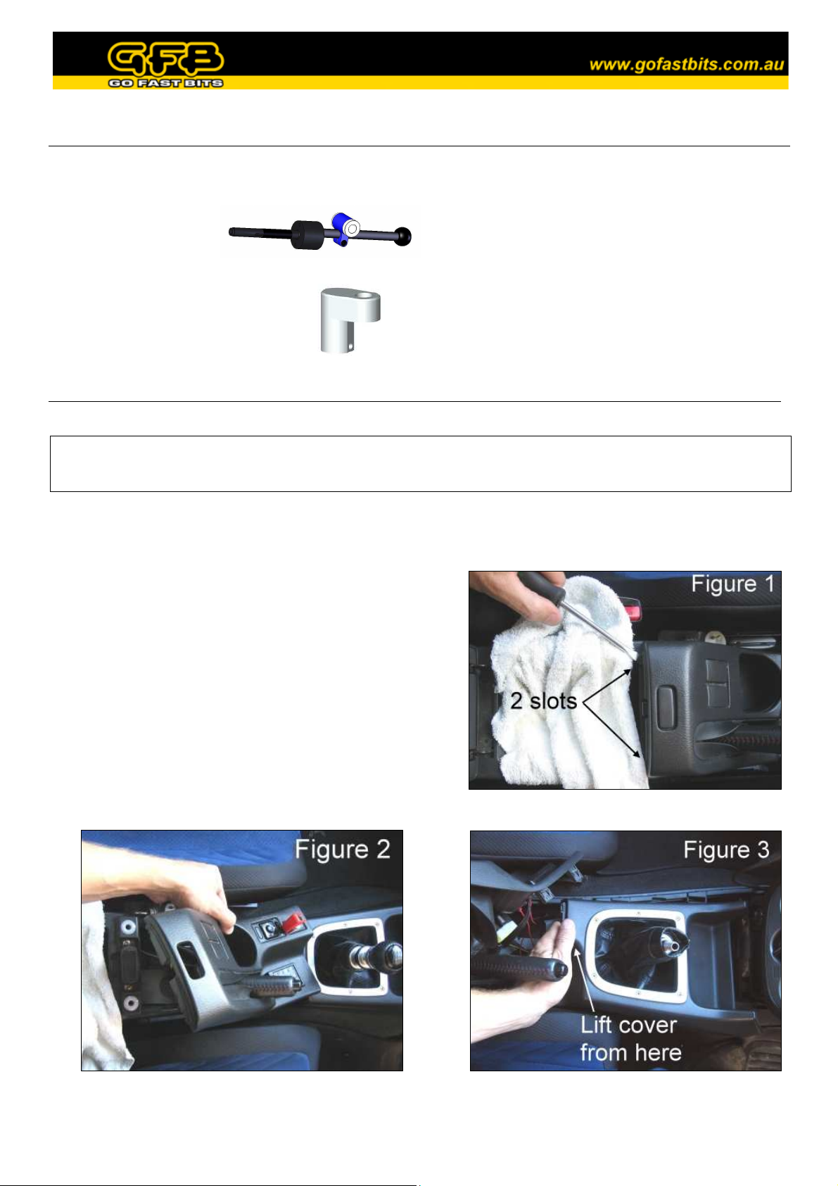
1. Lift the lid of the centre console between the seats
above the handbrake. On the plastic handbrake shroud
there are two slots, using the flat-blade screwdriver
padded with a rag, carefully lever the shroud up on
each side (there is a pop-type fastener on each side).
2. Lift the handbrake shroud out (taking care of wiring
still attached), to give you access to the gearstick
surround (figure 2).
3. Unscrew the gear knob and unclip the button fastener
on the leather shift boot. Gently lift the plastic
gearstick shroud up from the back, it is only lightly clipped in and does not need much force.
• 1 x 4mm hex key
• 1 x cable/zip tie
Required tools:
• 2 x 12mm spanner/wrench
• Medium flat-blade and Phillips screwdriver
• Side cutters/knife
• Circlip pliers (or pointy needle-nose pliers
will suffice)
• Rag
Page 2
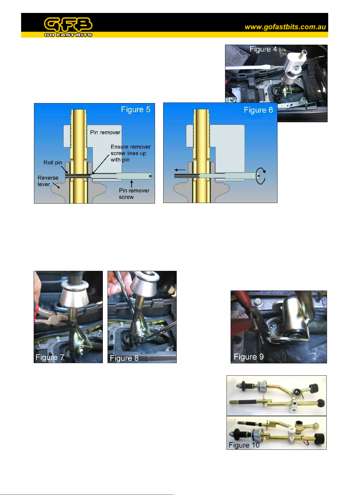
4. Slide the pin remover onto the top of the gearstick (fig. 4).
Thread the longer of the M5 slot screws into the threaded hole of
the pin remover, making sure to line up the end of this screw with
the roll pin as shown in figure 5. Watch the pin as you wind the
screw in, it should push easily out the other side (fig. 6). If not,
stop and check the screw is properly aligned with the pin.
5. Once the pin comes out completely, remove the screw and pin remover. The reverse lock cable will
spring down at this point; don’t worry, it will be retrieved during re-assembly.
6. Cut the cable tie that holds the reverse lock
cable to the gearstick (fig. 7). Using the two
12mm spanners, remove the bolt that holds the
linkage to the gearstick (fig. 8).
8. Transfer the ball cup and circlip to the GFB gearstick (the ball cup
spreads apart easily to allow this), making sure there is sufficient
grease in the cup. Remove the silver plastic boot collar (undo 2
phillips head screws from underneath), reverse lever, spring, and
rubber spring seat from the factory gearstick and fit them onto the
GFB gearstick (fig. 10). Slip the factory steel sleeve into the
bushings in the GFB gearstick, again ensuring there is sufficient
grease on both parts.
9. Replace the assembled GFB gearstick back into the factory
position, and fasten it in place with the circlip.
7. Use the circlip (or needle-nose) pliers to
remove the circlip retaining the gearstick ball
cup (fig. 9). Pull up on the gearstick as you
close the circlip, it should lift out once the
circlip clears its groove. Pull the reverse lock
cable out of the gearstick as you lift it out.
Page 3

10. At this point it is necessary to lock the reverse cable in an extended position in order to be able to
replace the roll pin. To do this, pull on the cable and simultaneously twist the linkage clockwise, then
pull it back to select reverse gear. You may need to vary the distance you extend the cable to properly
select reverse. Once reverse is selected, the reverse cable will remain extended when you let it go. If you
have difficulty at this point, it may help to temporarily bolt the linkage to the gearstick and use the
gearstick to help select reverse. Make sure to leave the linkage in reverse until the end of step 12.
11. If you have used the gearstick to assist in step 10,
it’ll help to unbolt it for this step. Slide the reverse
cable up into the top half of the gearstick. The hole
in the swage at the end of the cable should line up
with the slot in top of the gearstick (twist the cable
or rotate the gearstick if necessary). Line up the
hole in the reverse lever, then push the longer of the
M5 slot screws (the one used in step 4) through the
reverse lever, the gearstick, into the reverse cable
swage, and out the other side (fig. 11). This step
will line up all the parts and helps to guide the roll
pin in easily. If the reverse cable does not reach
high enough to insert the pin, re-check step 10.
12. Put the pin remover back onto the gearstick, and drop the roll pin into the threaded hole, followed by the
shorter of the two M5 slot screws. Make sure the end of the roll pin is lined up with the end of the long
M5 slot screw (fig. 11), then begin screwing it into the gearstick. If aligned correctly, the roll pin will
push the longer M5 slot screw out of the gearstick as it goes. Continue until the pin is pushed about
1mm BEYOND centre (figure 12). Now unwind the short M5 slot screw, spin the roll pin remover 180
degrees and push the pin back the other way until it is centred (fig. 13). This will ensure the end of the
cable is held in the middle of the gearstick, instead of rubbing against the side (look down the hole in the
top of the gearstick, you will be able to see the position of the cable).
13. Shift into neutral by pushing forward on the linkage, then check that the reverse lever slides up and
down smoothly. Now fasten the reverse cable to the gearstick with the supplied zip tie.
Page 4

14. IMPORTANT: Make sure the factory steel sleeve is inserted into
the white bushings of the gearstick clamp – without this sleeve the
shifter will not operate properly. Line up the sleeve with the holes
in the linkage and pass the factory bolt right through, securing it
with the nut (figure 14).
15. At this point you will need to decide how short you want the shift
throw to be. This is determined by the height of the clamp on the
gearstick relative to the pivot ball – the higher the clamp, the
shorter the throw (Note: the shorter you make the throw, the more
force will be required to shift, this is normal).
Note that as you slide the clamp up and down, the neutral position
of the gearstick will move slightly. When you have selected a
suitable position for the clamp, check that you can select all gears
(including reverse) smoothly, making sure the linkage does not hit
the transmission tunnel in 1st gear (see arrow in figure 14).
Replace the plastic shrouds in the reverse order of removal.
Notes on short shifters – worth a read…
It is a common misconception that short shifters are hard on synchros, and that premature wear is likely.
This is not true in the slightest. The only thing that can possibly cause accelerated synchro or gearbox wear
is poor shifting technique, or rushing gear changes. It is possible that having a short shifter may encourage
abusive shifting, so the limits of the synchros should always be observed.
The shifter is merely a lever that transmits movement to the gearbox. When you shorten the shift throw, it
feels like you are working the ‘box harder, because more force is required to shift. In actual fact, the force
that the gearbox requires to shift gears is exactly the same – the shifter cannot change that. However, by
reducing the throw, you also reduce the amount of leverage (or more correctly, mechanical advantage) that
you have over the gearbox, and therefore you have to apply more force to the gearstick to achieve the same
shifting force at the gearbox.
Also note that Subaru themselves have progressively shortened the shift throw of the WRX significantly
over the years, from about 70mm per gate in the early MY97 models down to 50mm for the post MY01
models, and the STi is even shorter again.
So next time someone tells you your synchros will wear out because of your shifter, you’ll be able to set the
record straight.
Subarus are commonly known for a notchy shift feel, but the good news is the shift quality of your gearbox
can be vastly improved by using good quality oil. The oil used by Subaru is often cheap and not ideal, and
replacing it with a reputable synthetic (not just an additive) will do wonders for cranky ‘boxes, particularly
when selecting 1st gear or when the oil is cold.
If you would like to shorten the shift throw of your GFB shifter even further, you can purchase the linkage
clamp separately that brings this kit up to the full 4002 spec, meaning the shift throw can be reduced by
another 15%. The part number for this linkage clamp is 4202, contact GFB on +61 (0)2 9534 0099 or email
sales@gfb.com.au for more info.
 Loading...