

Page 1

Brief instructions
Door control
TS 971
Automatic control panel with radio
Version: 51171638
Version: e / 01.2015
0000000 0000 51171638 XXXXX
-aus-
Page 2

GfA-ELEKTROMATEN
Australia Pty Ltd
P.O. Box 267
Roseville 2069 NSW
Telephone: 02 9882 2782
Facsimile: 02 9882 2783
Email: [email protected]
Web: www.gfa-elektromaten.net
2
Page 3

Contents
1 General safety information ............................................................................................ 5
2 Technical data .............................................................................................................. 6
3 Electrical installation ..................................................................................................... 7
Mains supply ..................................................................................................................... 7
Connection cable connection overview ............................................................................. 8
Limit switch configuration, screwable version up to year of construction in 1997 .............. 9
Limit switch configuration, single limit switches ................................................................. 9
Overview of control ......................................................................................................... 10
4 Starting up the control ................................................................................................. 11
DES: Rapid adjustment of final limit positions ................................................................. 11
NES: Rapid adjustment of final limit positions ................................................................. 12
5 Electrical installation – control accessories .................................................................. 13
External supply X1 .......................................................................................................... 13
Emergency stop X3 ......................................................................................................... 13
Automatic closing, On/Off X4 .......................................................................................... 13
External Control device X5 .............................................................................................. 13
Photo cell X6 ................................................................................................................... 13
Light curtain X6 ............................................................................................................... 14
Radio receiver X7............................................................................................................ 14
Pull switch X7 .................................................................................................................. 14
Intermediate stop X8 ....................................................................................................... 14
Red/green traffic lights X20 / X21 ................................................................................... 14
Magnetic brake X20 / X21 ............................................................................................... 14
Connection of spiral cable ............................................................................................... 15
WSD door-module (Wireless Safety Device) .................................................................. 16
Teach-in of WSD door-module ........................................................................................ 17
Completing the electrical installation ............................................................................... 17
6 Control programming .................................................................................................. 18
7 Table menu items ....................................................................................................... 19
Door operating modes ..................................................................................................... 19
Door positions ................................................................................................................. 20
Door functions, ................................................................................................................ 21
Safety functions .............................................................................................................. 25
3
Page 4
DI / FI settings ................................................................................................................. 26
Extended door functions .................................................................................................. 27
Teach-in of handheld transmitter ..................................................................................... 28
Maintenance cycle counter .............................................................................................. 29
Readout of Data memory ................................................................................................ 30
Deleting of all settings ..................................................................................................... 3 0
Reading out WSD door-module data............................................................................... 31
8 Safety devices ............................................................................................................ 31
X2: Input, safety edge ..................................................................................................... 31
EMERGENCY operation ................................................................................................. 32
9 Status display ............................................................................................................. 33
Faults .............................................................................................................................. 33
10 Explanation of symbols ............................................................................................... 38
11 Declaration of Incorporation/Declaration of Conformity ................................................ 40
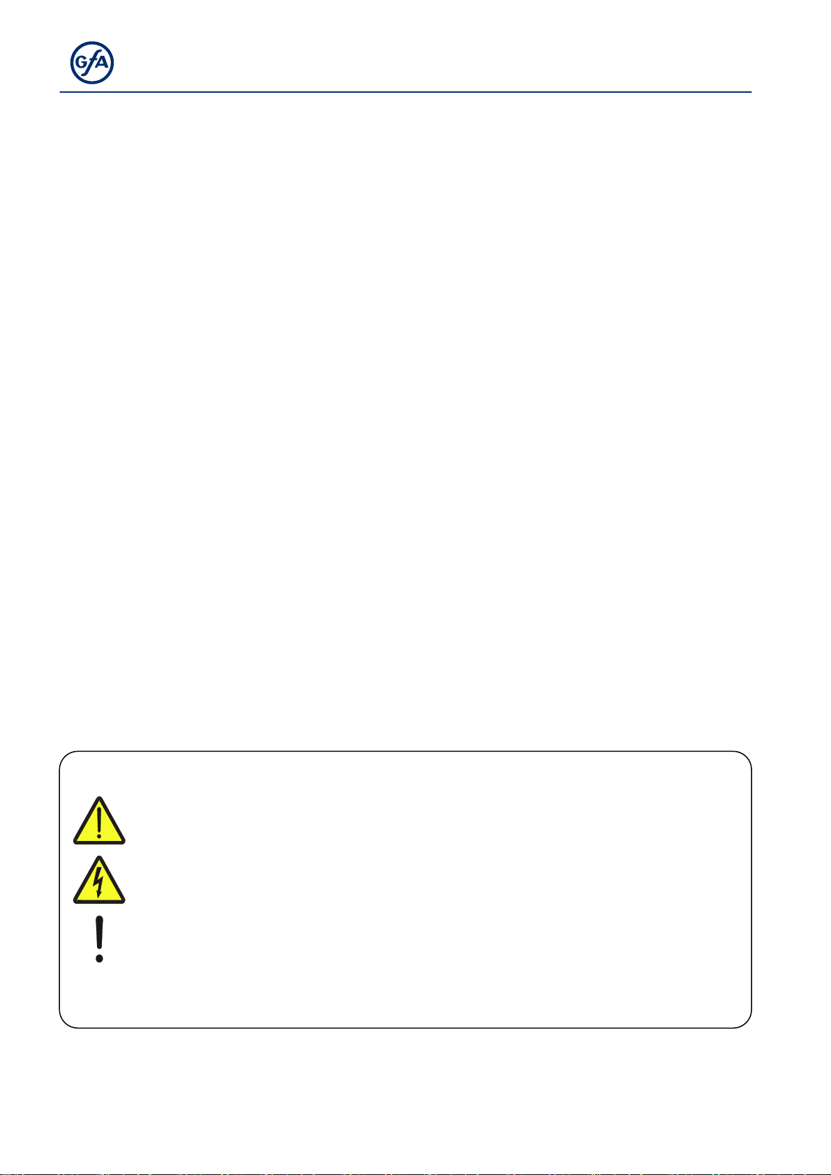
Symbols
Warning - Risk of injury or danger to life!
Warning - Danger to life from electric shock!
Note - Important information!
▶
Prompt - Required action!
Illustrations show example products. Differences from the delivered product are possible.
4
Page 5

1 General safety information
Specified normal use
The door control is intended for a power-operated door with a drive unit (NES/DES GfA limit
switch system).
The safe operation is only guaranteed with specified normal use. The drive unit is to be
protected from rain, moisture and aggressive ambient conditions. No liability for damage
caused by other applications or non-observance of the information in the manual.
Modifications are only permitted with the agreement of the manufacturer. Otherwise the
Manufacturer’s Declaration shall be rendered null and void.
Safety information
Installation and commissioning are to be performed by skilled personnel only.
Only trained electrical craftsmen are permitted to work on electrical equipment. They must
assess the tasks assigned to them, recognise potential danger zones and be able to take
appropriate safety measures.
Installation work is only to be carried out with the supply off.
Observe the applicable regulations and standards.
Coverings and protective devices
Only operate with corresponding coverings and protective devices.
Ensure that gaskets are fitted correctly and that cable glands are correctly tightened.
Spare parts
Only use original spare parts.
5
Page 6
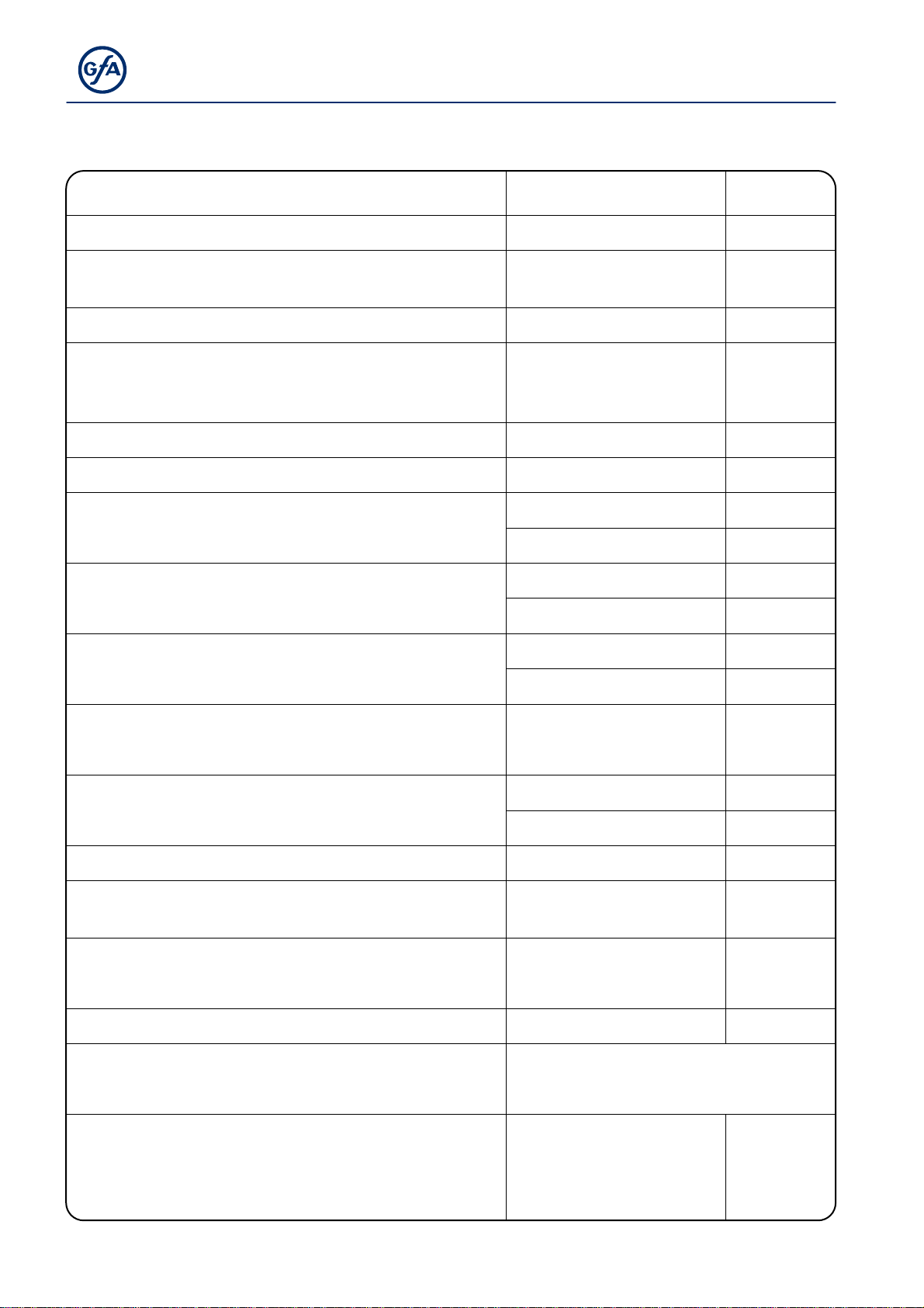
2 Technical data
Series TS 971
Dimensions W x H x D 155 x 386 x 90 mm
Installation Vertical, free of vibration
Operating frequency 50 / 60 Hz
1 N~220-230 V, PE
Supply voltage (+/- 10%)
Output power for drive unit, maximum 3 kW
Protection per phase, on-site 10-16 A
3 N~220-400 V, PE
3~220-400 V, PE
External supply voltage:
(internal electronic protection)
External supply voltage: X1/L, X1/N
(protection via F1 micro-fuse)
24 V DC
0.35 A
1 N~230 V
1.6 A time-lag
24 V DC
Control inputs
Type 10 mA
Relay contacts
Loading of relay contacts,
ohmic/inductive
2 potential-free
changeover contacts
230 V AC, 1 A
24 V DC, 0,4 A
Control power consumption 18 W
Temperature range
Operation: -10..+50
Storage: +0..+50
°C
Air humidity
up to 93 %
non-condensing
Protection class of housing IP54
Compatible GfA limit switch
Integrated radio receiver
WSD (Wireless Safety Device)
Handheld transmitter
NES (mechanical limit switch)
DES (digital limit switch)
2.4
434
6
GHz
MHz
Page 7
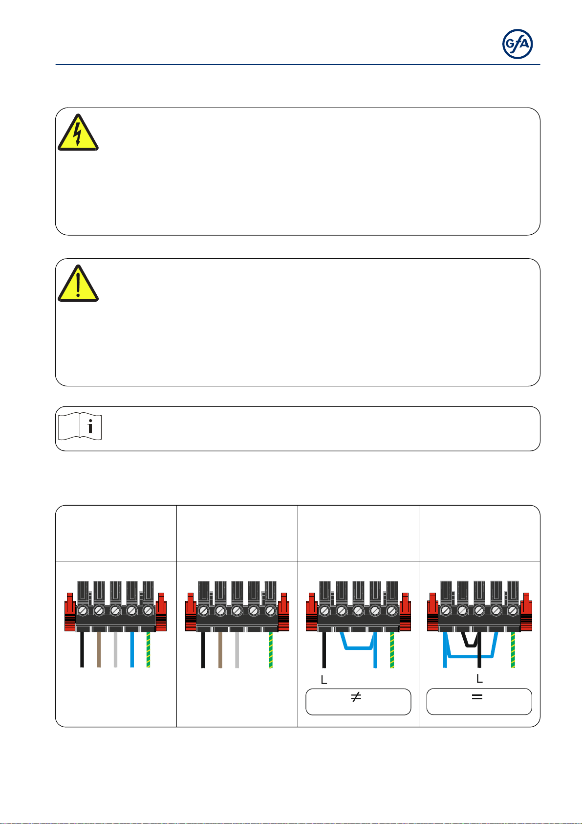
3 Electrical installation
Warning - Danger to life due to electrical current!
Disconnect the cables (mains OFF) and check that the supply is off
Observe the applicable regulations and standards
Ensure proper electrical connection
Use suitable tools
On-site backup fuse and disconnector unit!
Only use current sensitive earth leakage circuit breakers type B for FI-drive units
Connection to the indoor installation via an all-pole disconnector unit, with current
≥ 10 A as per EN 12453 (e.g. CEE plug connector, main switch)
Observe the installation instructions of the drive unit!
Mains supply
3~, N, PE
220 – 400 V
50 - 60 Hz
L1L2L3NPE
3~, PE
220 – 400 V
50 - 60 Hz
L1L2L3 PE
1~, N, PE, sym.
220 - 230 V
50 - 60 Hz
N
PE
1~, N, PE, asym.
220 - 230 V
50 - 60 Hz
NPE
SI 25.15 WS, SI 45.7 WS
SI 25.15 WS, SI 45.7 WS
7
Page 8
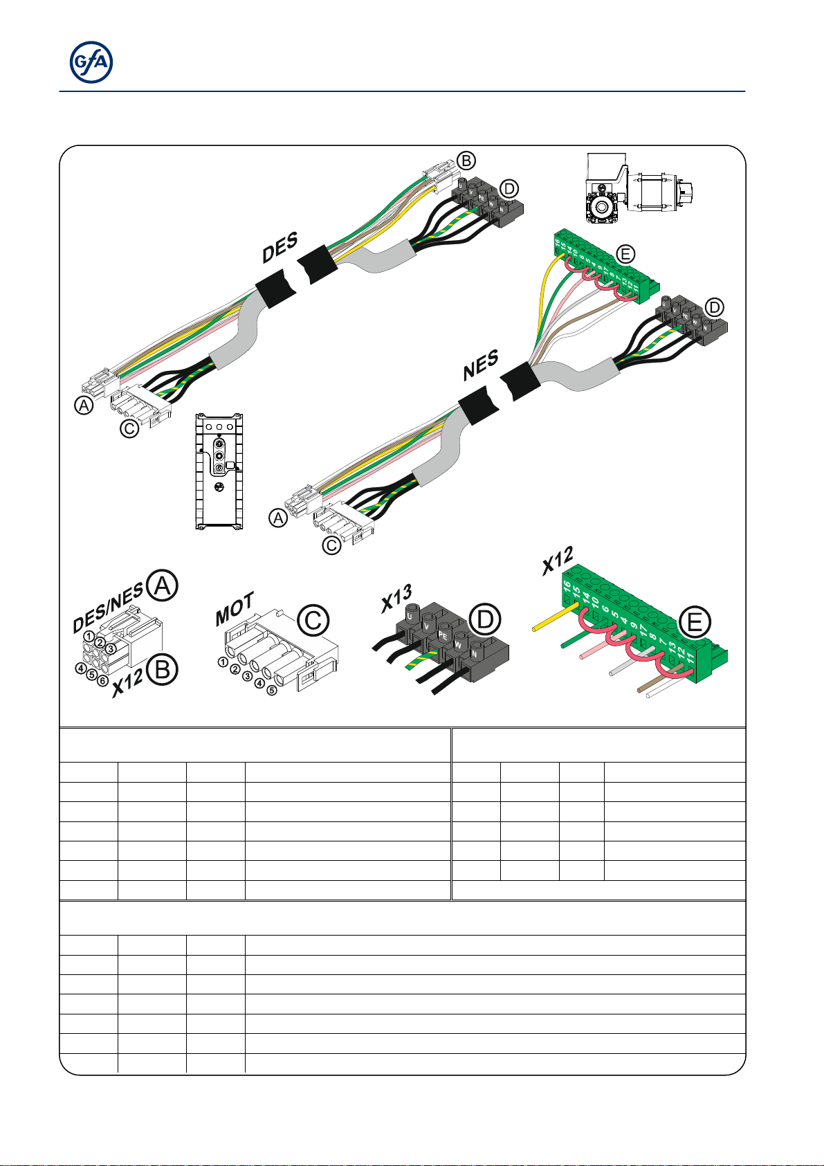
Connection cable connection overview
Ⓐ DES → Ⓑ X12 DES Ⓒ MOT → Ⓓ X13
Pin Core Pin Description: Pin Core Term. Description:
① 5/wh ① +24 V safety circuit ① 3 W Phase W
② 6/bn ② Channel B (RS485) ② 2 V Phase V
③ 7/gn ③ Ground ③ 1 U Phase U
④ 8/ye ④ Channel A (RS485) ④ 4 N Neutral conductor (N)
⑤ 9/gy ⑤ Safety circuit ⑤ PE PE
⑥ 10/pk ⑥
8 V DC supply voltage
Ⓐ NES → Ⓔ X12 NES
Pin Core Term. Description:
① 5/wh 11
② 6/bn 12
③ 7/gn 6 S3 Open limit switch
④ 8/ye 15 S6 Auxiliary limit switch
⑤ 9/gy 8 S4 CLOSE limit switch
⑥ 10/pk 4 Safety circuit
Limit switch common +24 V, wire link to: 7, 9, 5, 14
S5 Auxiliary limit switch
8
Page 9
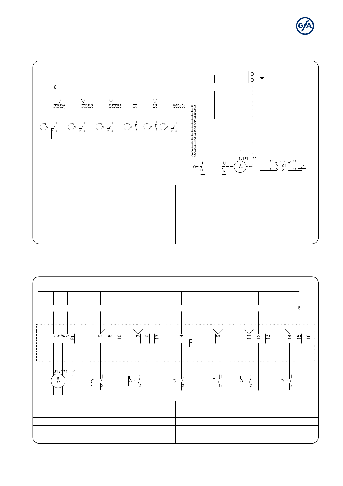
Limit switch configuration, screwable version up to year of construction in 1997
A
A
A
A
A
W1
5
6710 93214(N)
3
2
S6 S5 S3 S1 S2 S4
1
5
4
X12
S10 F1
M1
F1 Thermal contact X12 Limit switch board
G1 Rectifier S1 Emergency OPEN limit switch
M1 Motor S2 Emergency CLOSE limit switch
S10 Emergency manual operation S3 OPEN limit switch
W1 Connection cable S4 CLOSE limit switch
Y1 Spring-loaded brake S5
S6
uxiliary limit switch
uxiliary limit switch
G1
Y1
Limit switch configuration, single limit switches
W1
5 671093214PE
A1
M1 S10 F1S4S3 S5 S6
1 Terminal box S3 OPEN limit switch
F1 Thermal contact S4 CLOSE limit switch
M1 Motor S5
S10 Emergency manual operation S6
W1 Connection cable
uxiliary limit switch
uxiliary limit switch
9
Page 10
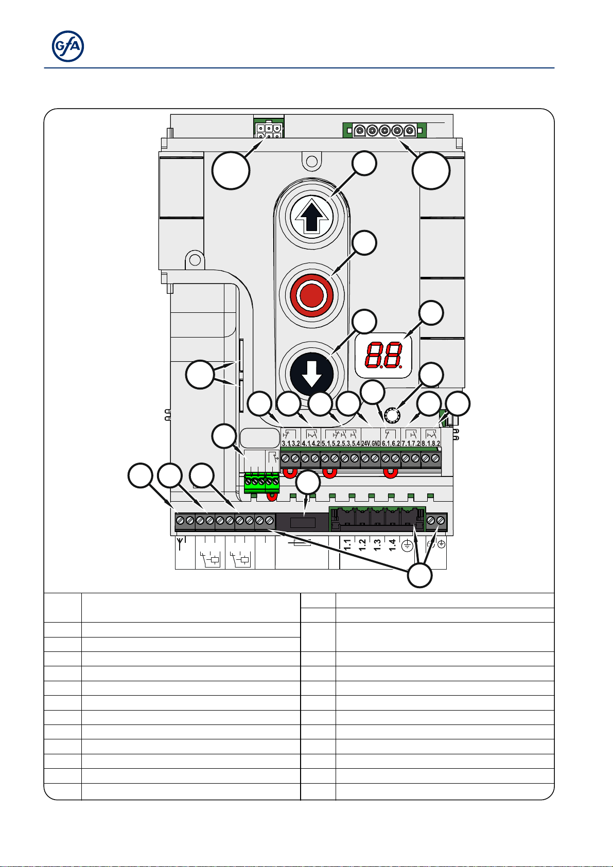
Overview of control
A
DES/
NES
S1 1
MOT
S12
V1
S13
UBS S
X6
X3X2X4 X5 X
X7 X8
971
2.1
2.3
2.5
2.2
2.4
F1
1.8
1.9
20.1
20.2
20.3
F1 = 1,6A t
ANT
X20X21T
21.1
21.2
21.3
GN D
X1
DES/
NES
F1 Micro-fuse 1.6 A time-lag
MOT Motor socket
S Selector switch X3 Emergency STOP control device
S11 OPEN push-button X4
S12 STOP push-button X5 Control device, external three push-button
S13 CLOSE push-button X6 Through / reflective photo cell
T Internal aerial, 434 MHz X7 Pull switch, external radio receiver
UBS Universal command sensor socket X8 Intermediate stop On/Off
V1 Display X20 Potential-free relay contact 1
X21 Potential-free relay contact 2
DES or NES limit switch socket
X 24 V mains supply, external devices
X1 Mains supply
X2
Safety edge and
door safety switch
utomatic closing On/Off
10
Page 11
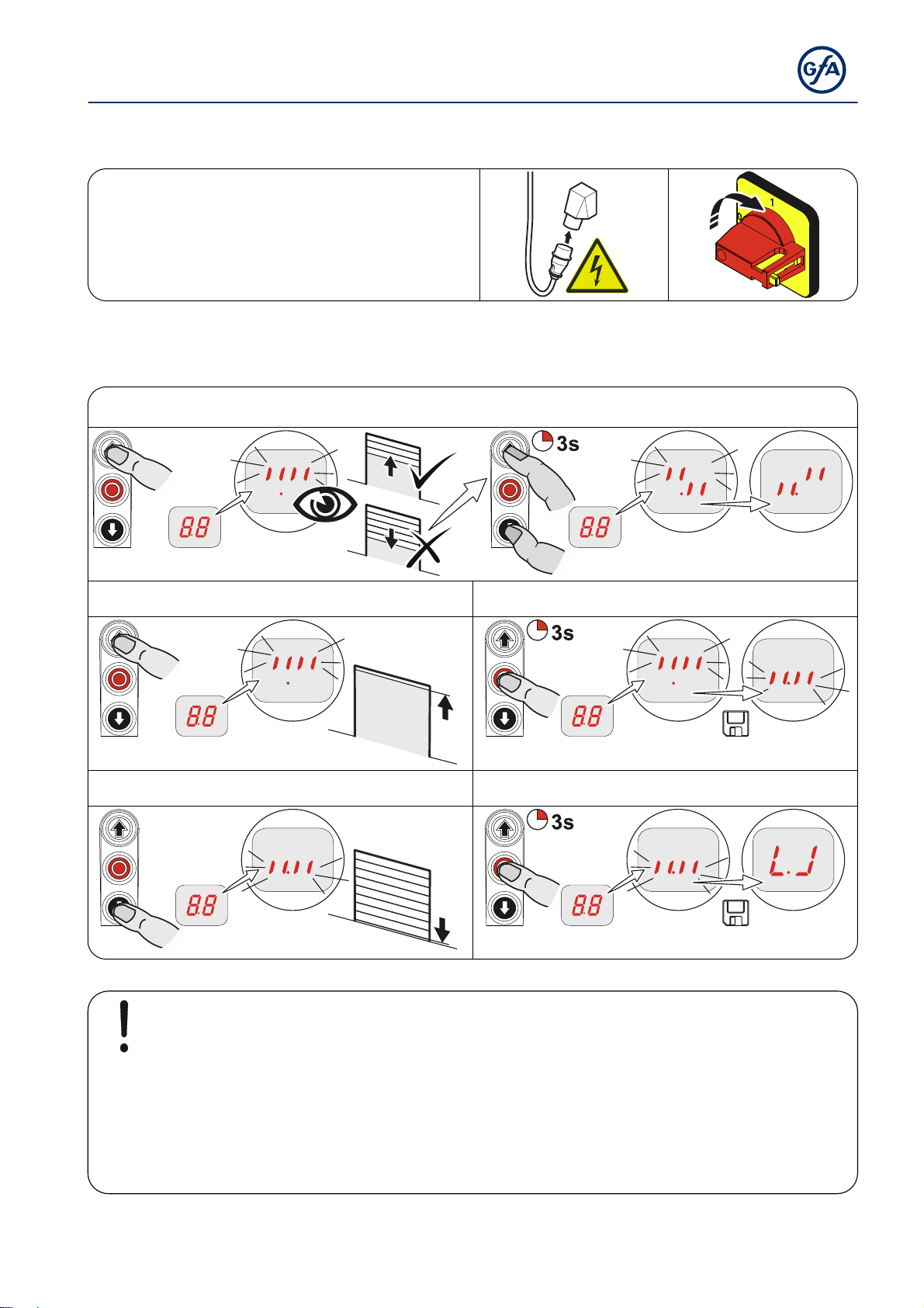
4 Starting up the control
▶ Supply cables
Insert / switch on
DES: Rapid adjustment of final limit positions
1. Check output rotating direction
2. Move to OPEN final limit position 3. Save OPEN final limit position
4. Move to CLOSE final limit position 5. Save CLOSE final limit position
Note!
The rapid adjustment is complete, "Hold-to-run" door operating mode is active
Change of OPEN/CLOSE final limit positions via menu items "1.1" to "1.4"
Pre-limit switch safety edge is set automatically
Changing the pre-limit position is possible via menu "1.5"
11
Page 12
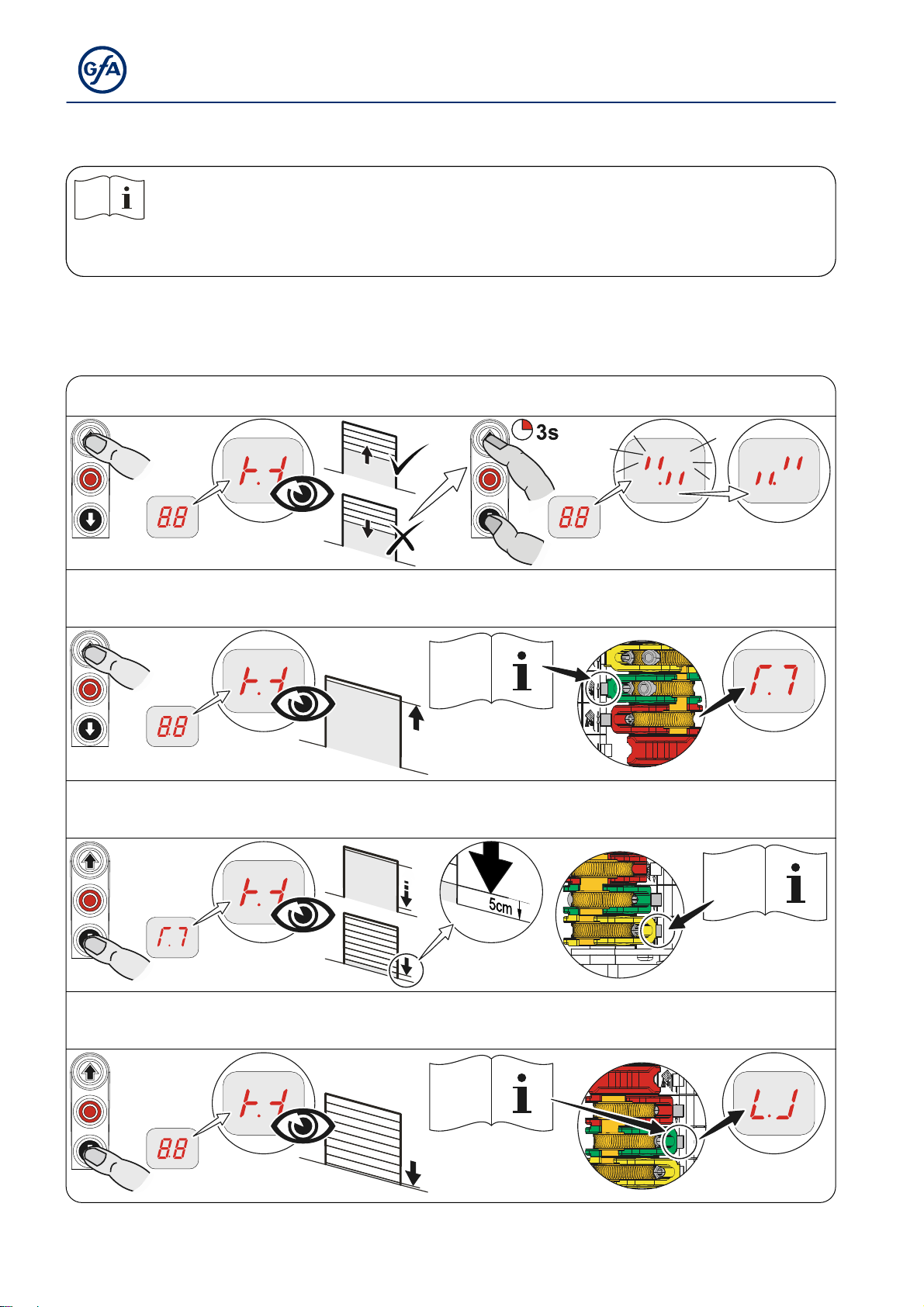
Observe the installation instructions of the drive unit!
For adjusting the mechanical limit switch, see the drive unit installation
instructions
NES: Rapid adjustment of final limit positions
1. Check output rotating direction
2. Move to OPEN final limit position and adjust S3 OPEN limit switch
3. Move to CLOSE final limit position 5cm above the ground and adjust S5 pre-limit switch
4. Move to CLOSE final limit position and adjust S4 CLOSE limit switch
12
Page 13
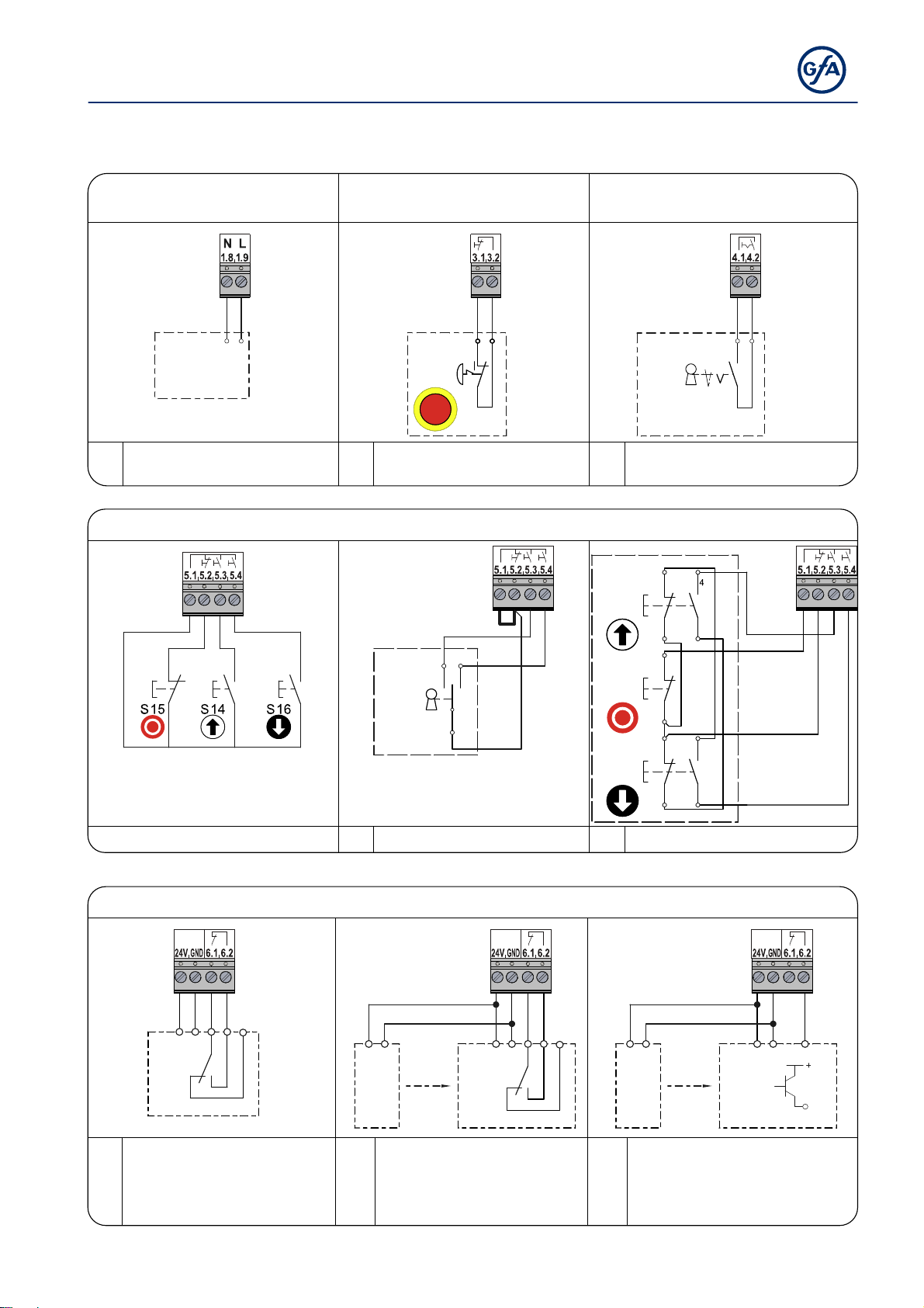
A
A
A
A
A
A
0
5 Electrical installation – control accessories
External s uppl y X1
Emergency st op X 3
Automatic closing , On/ Off X 4
External supply X1 Emergency stop X3 Automatic closing, On/Off X4
X1
A1
X3
A2
S15
2
S17
1
A3
1 External device
Emergency stop Key switch
External C ontr ol de vice X 5
X5
2 Control device
External Control device X5
X5
A4
S17
1
2
P
3 Control device
A6
2
S14
1
2
S15
1
X4
4
12
3
X5
3
2
S16
1
Photo cell X6
4 Key push-button
6 Three push button
Photo cell X6
X6
12345
24V
A8
8
Reflective
photo cell
A9 Transmitter A11 Transmitter
A10 Receiver A12 Receiver
12
24V
A9
Through-beam
photo cell
X6
A10
1234
24V
5
12
24V
A11
Through-beam
photo cell
4
3
X6
12 3
24V
PNP
A12
13
Page 14
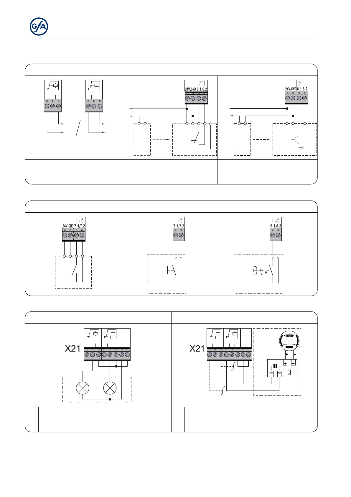
Light curt ain X6
Light curtain X6
X6
A26
1234
24V
24V
24V*
5
12
24V
A27
X21
21.1
21.2
21.3
X20
24V
24V*
20.1
20.2
20.3
24V
24V*
24V
24V*
12
24V
A25
X20 Function relay Light curtain Light curtain
X21 Function relay A25 Transmitter A27 Transmitter
Test light curtain A26 Receiver A28 Receiver
Radio receiv er X7
Pull switch X7
Intermediate stop X8
Radio receiver X7 Pull switch X7 Intermediate stop X8
X7
1234
24V
X7
S19
X8
4
12
S17
3
A13
A14
Red/green traffic lights X2 0 / X 21
Magnetic brake X20 / X21
Red/green traffic lights X20 / X21 Magnetic brake X20 / X21
A15
X6
12 3
24V
PNP
A28
4
3
X20/
H2
21.3
21.2
H1
20.1
20.2
20.3
21.1
1.9
1.8
X20/
21.2
21.3
H1 Traffic light, green G1 Rectifier
H2 Traffic light, red Y1 Magnetic brake
14
20.1
20.2
20.3
21.1
1.8
Y1
1.9
C1
G1
Page 15
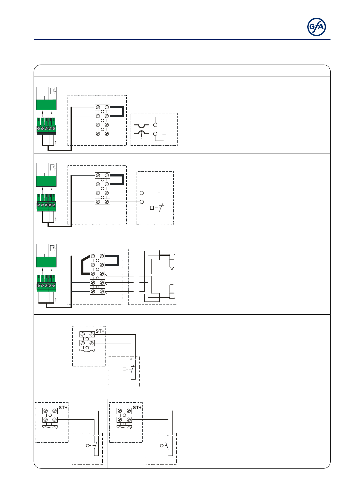
A
A19A
A
Connection of s piral c abl e
2.3
2.5
2.2
2.4
X2
234
2.3
2.5
2.2
2.4
X2
234
2.3
2.5
2.2
2.4
X2
234
A18/A19
Electrical safety edge
2.1
1
2
3
4
ST+
ST
SK1
SK2
A18
Pneumatic safety edge
2.1
1
2
3
4
ST+
ST
SK1
SK2
A18
Optical safety edge system
2.1
1
2
3
4
ST+
ST
SK/b
SK/g
SK/w
A19
Door safety switch
ST
A18/A19
S30/
S31
A20
Door safety switch - Crash switch
ST
2
A18/A19
S38
1
A21
Connection of spiral cable
A18 Junction box
ST+ Mains supply
ST Input for door safety switch
SK1
Input electrical safety edge
SK2
R1
8K2
B1
R2
1K2
DW
B2
br
gn
w
2
1
B3
ST
S39
A22
B1 Electrical safety edge
R1 End of line resistor (8k2)
X2 Door control socket
A18 Junction box
ST+ Mains supply
ST Input for door safety switch
SK1
Input pneumatic safety edge
SK2
DW Pneumatic switch
R2 End of line resistor (1k2)
X2 Door control socket
A19 Junction box
ST+ Mains supply
ST Input for door safety switch
SK/b Mains supply (brown)
SK/g Output (green)
SK/w Earth (white)
B2 Optical transmitter
B3 Optical receiver
X2 Door control socket
A18
Junction box
19
A20 Junction box switch
S30 Pass-door switch
(NC contact)
S31 slack-rope contact
(NC contact)
A18
Junction box
21 Junction box switch
S38 Crash switch
2
1
(NC contact)
22 Junction box switch
S39 Crash switch
(NO contact)
15
Page 16
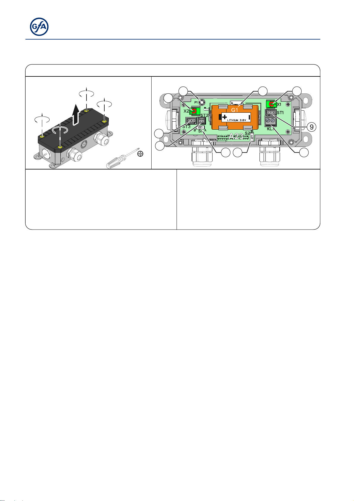
A
WSD door-module (Wireless Safety Device)
WSD door-module (Wireless Safety Device)
Direction for opening
1
3
4
4
5
6
2
23 WSD door module ⑥ ST2 Socket for system-2 connection cable
① P1 WSD door-module push-button ⑦ S2 Safety edge evaluation switch:
② S1
Switch “A” for system 1, switch “B” for system 2
Optical (upper changeover position, “IR”)
③ G1 Lithium battery, 9000 mAh Electrical (lower changeover position)
④ X1/2 Connection point for door safety switch ⑧ KL1 Terminal for:
⑤ ST3
⑨ ST1 Socket for optical sensor
Socket for optical sensor / System-2
connection cable
Electrical safety edge
87
16
Page 17
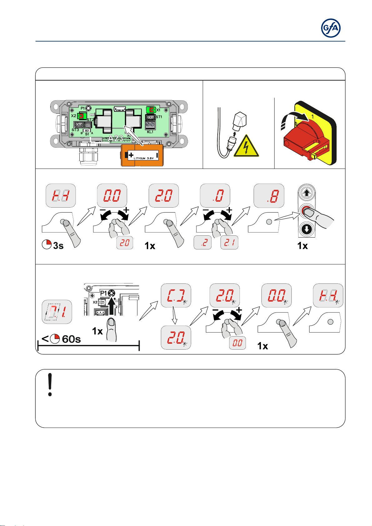
Teach-in of WSD door-module
Teach-in of WSD door-module
Insert battery Supply cables insert / switch on
Activate Channel 8, for example
Available channels
Teach in WSD door-module connected, dot on right is lit
Note!
Use of a safety edge
only possible via menu item "0.1",
door operating mode “3”, “4” or “6”
Completing the electrical installation
If required, connect other electrical equipment and/or safety devices. Install and tighten cable
entries and/or cable glands.
17
Page 18
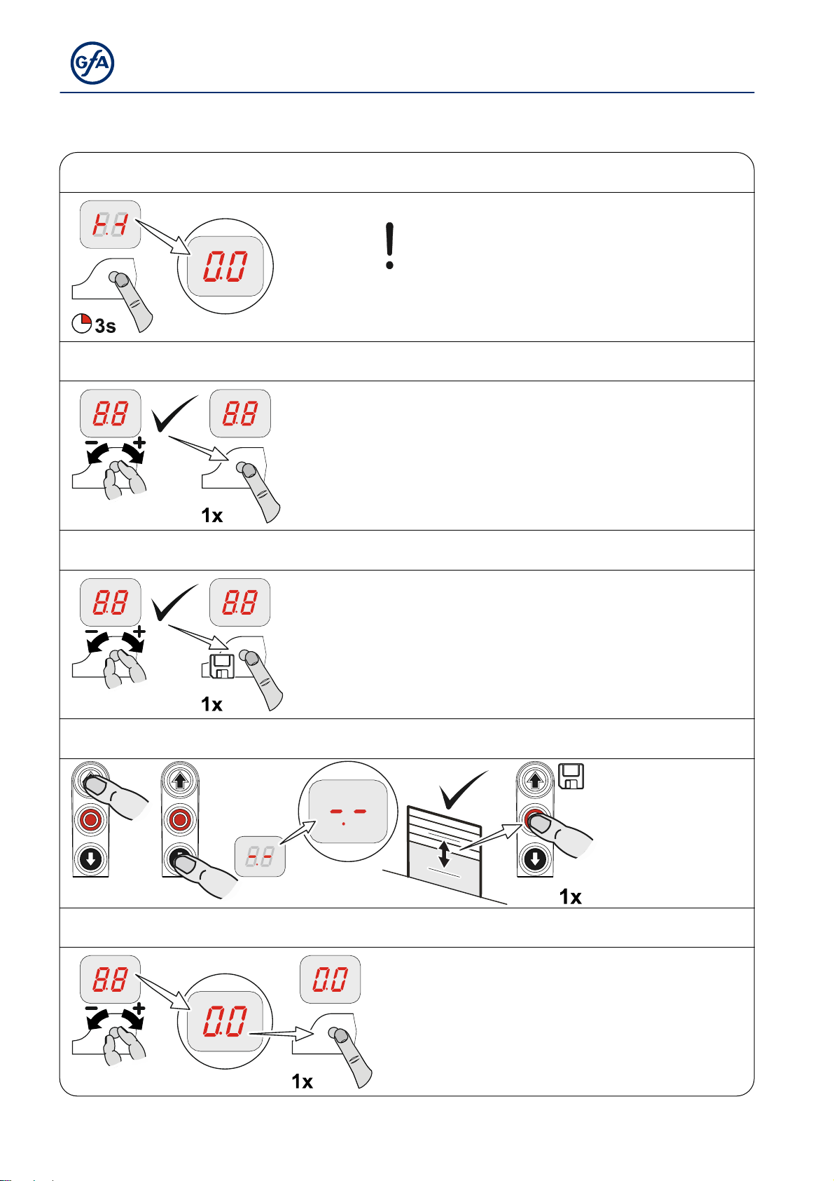
6 Control programming
1. Start programming
2. Select menu item and confirm
Note!
Possible after rapid adjustment of final
limit positions
3.a) Set and store functions
3.b) Set and store positions
4. Exit programming
18
Page 19
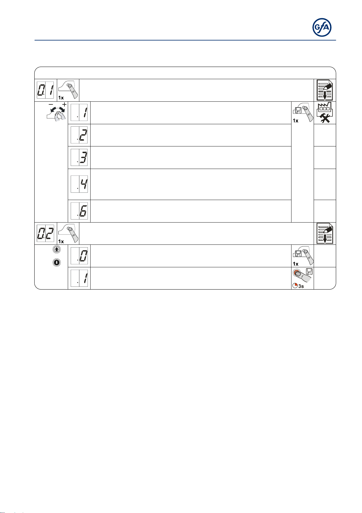
7 Table menu items
Door operat in g m odes
Door operating mode
OPEN
CLOSE
OPEN
CLOSE
Hold-to-run
Hold-to-run
Self-hold
Hold-to-run
Door operating modes
OPEN
CLOSE
OPEN
CLOSE
Self-hold
Self-hold
Self-hold
Self-hold, CLOSE hold-to-run release via
external X5 control device
OPEN
CLOSE
Hold-to-run
Hold-to-run with active safety edge
Output rotating direction
Maintain output rotating direction
Change output rotating direction
19
Page 20
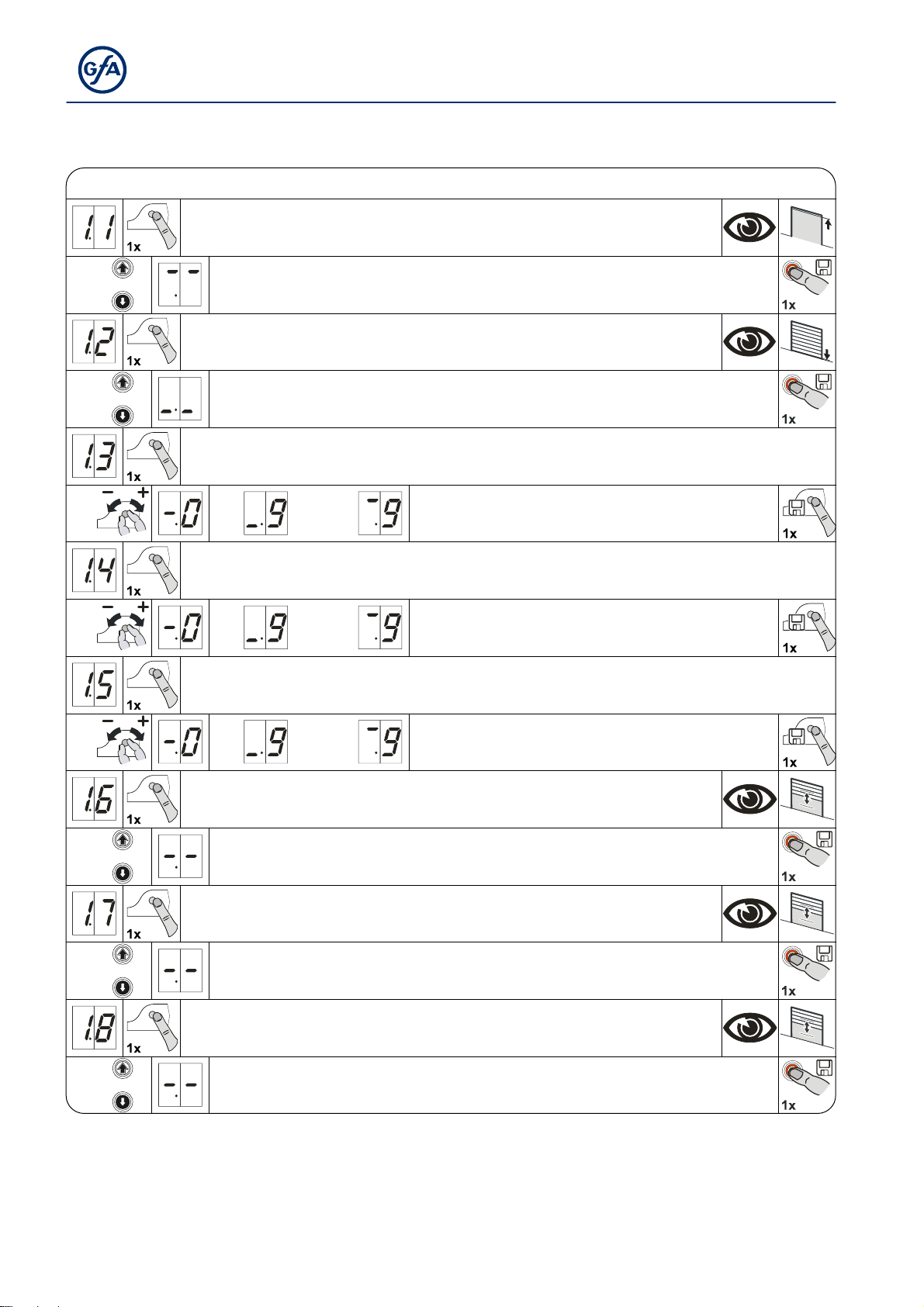
–
Door positions
Door positions
OPEN final limit position, coarse correction (DES)
Approach and store desired door position
CLOSE final limit position, coarse correction (DES)
Approach and store desired door position
OPEN final limit position, fine correction (DES)
CLOSE final limit position, fine correction (DES)
Fine-correction pre-limit switch for safety edge (DES)
Adjust intermediate open X8 (DES)*
Approach and store desired door position
Setting for position of relay 1 switching point (DES)*
Select relay function via menu item 2.7
Approach and store desired door position
Without door movement,
[ + ] OPEN correction
[
] CLOSE correction
Without door movement,
[ + ] OPEN correction
[ – ] CLOSE correction
Without door movement,
[ + ] OPEN correction
[ – ] CLOSE correction
Setting for position of relay 2 switching point (DES)*
Select relay function via menu item 2.8
Approach and store desired door position
*) Menu items 1.6 to 1.7 disappear at NES. The switching point must be adjusted via the S6 auxiliary limit switch
at the drive unit.
20
Page 21
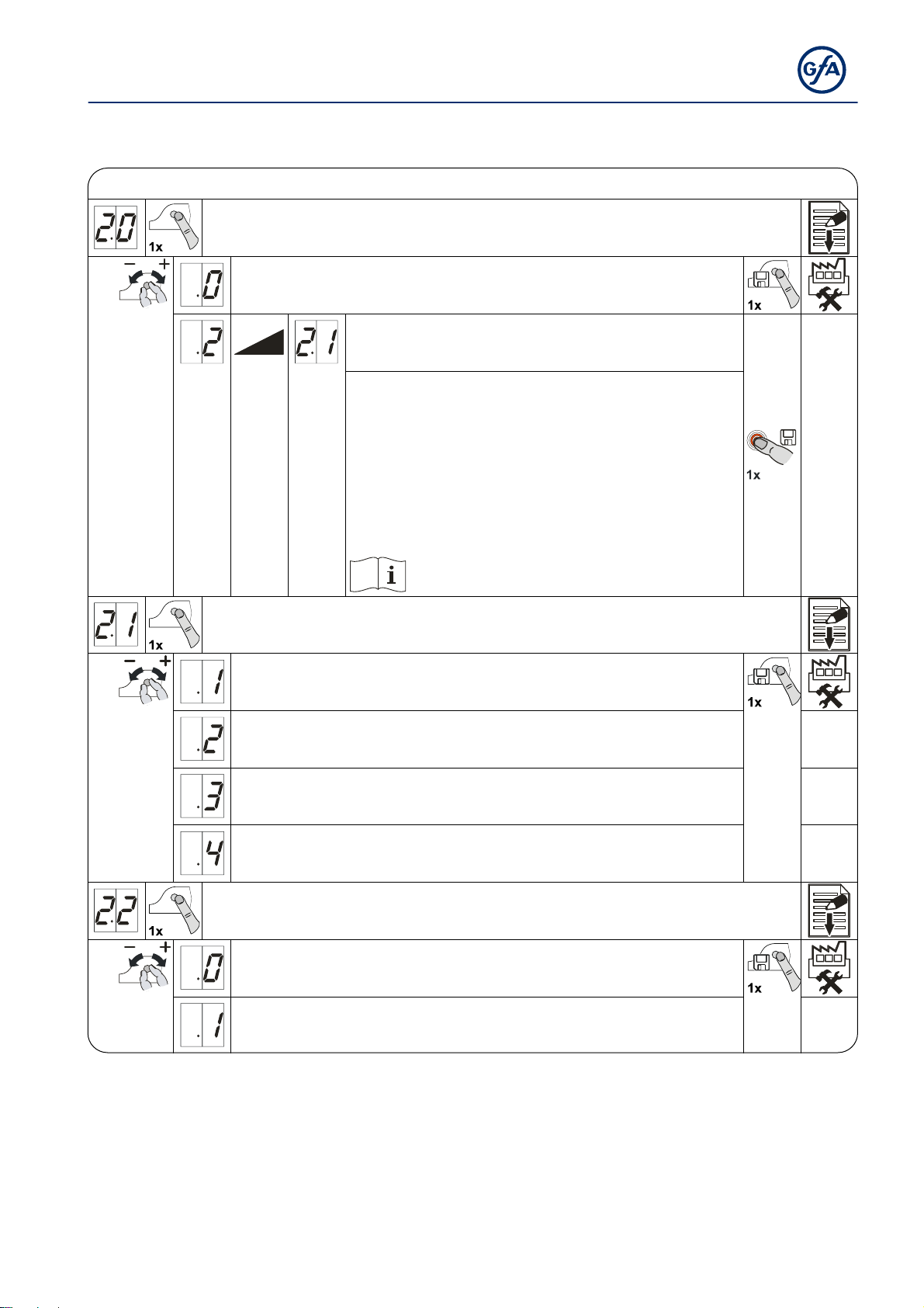
Door functions,
Door functions, part 1
Safety device
Spiral cable
Teach-in of WSD door-module wireless safety device
2 to 2.1: Manual channel selection
Up to 20 doors: Do not assign any radio channel
twice.
If more than 20 doors: Ensure maximum distance
between the door controls with the same channels.
Note taught-in channels in the controls housing.
Important for service work.
Pay attention to the WSD door-module manual
Safety edge function in the pre-limit area
Safety edge active
Safety edge inactive
Ground adjustment (DES)
(Activation of safety edge at ground contact)
Reversal movement in upwards direction in overrun area (DES)
Overrun correction (DES)
Off
On
(Do not use with ground adjustment)
21
Page 22
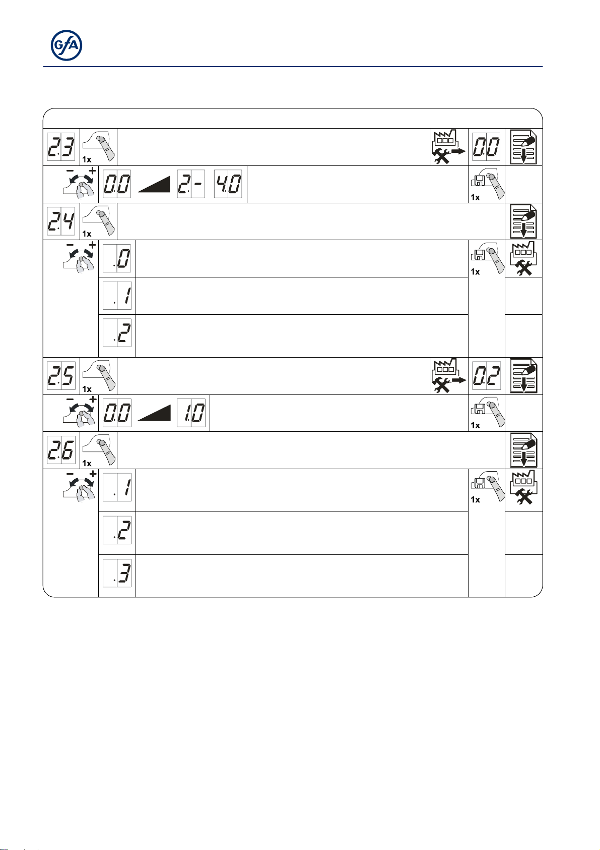
Door functions, part 2
Automatic closing
Extended photo cell function
Off
Cancel automatic closing and CLOSE command
0 to 240 seconds
Vessel recognition
Cancellation of automatic closing and CLOSE-command
if photo cell activation duration > 1.5 seconds
Reversing
0 = Off
1 to 10 safety-device activations
Pull switch or radio receiver function X7
Type of impuls 1
Door is in OPEN final limit position CLOSE command
Door is not at OPEN final limit position OPEN command
Pulse type 2
Command sequence
OPEN – STOP – CLOSE – STOP – OPEN
Type of impuls 3
OPEN command only
22
Page 23
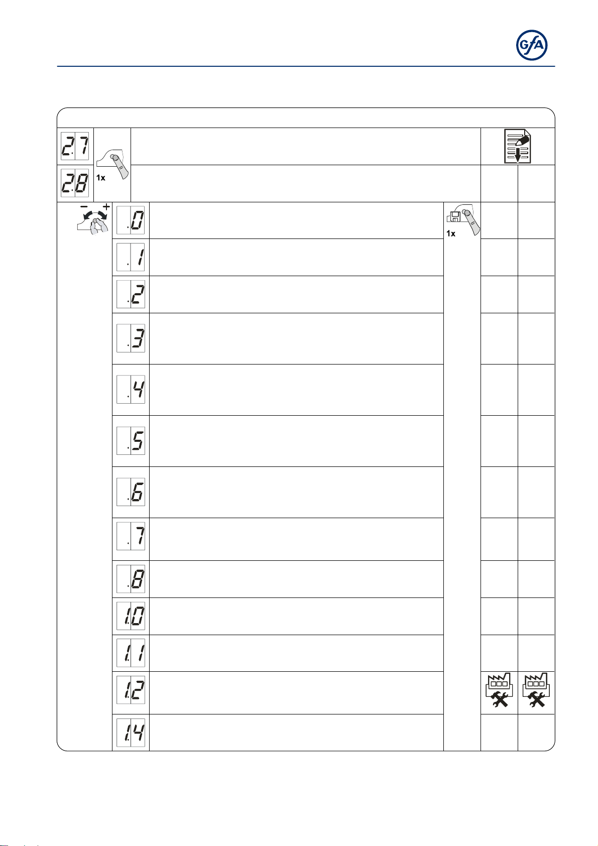
Door functions, part 3
Relay function on X20
Relay function on X21 X20 X21
Off
Impuls contact*
for 1 second
Permanent contact*
Red lamp, permanently lit during door movement
OPEN final limit position Flashing for 3 seconds
CLOSE final limit position Flashing for 3 seconds
Red lamp, permanently lit during door movement
OPEN final limit position Flashing for 3 seconds
CLOSE final limit position Off
Red lamp, permanently lit during door movement
OPEN final limit position Permanently lit for 3 seconds
CLOSE final limit position Permanently lit for 3 seconds
Red lamp, permanently lit during door movement
OPEN final limit position Permanently lit for 3 seconds
CLOSE final limit position Off
Dock leveller release or
permanent green light
Active only in OPEN final limit position
Permanent contact
in CLOSE final limit position
Light sensing device
1-second pulse at each OPEN command
Permanent contact at door position*
Brake control
Active during operation
Inactive at stop
Light curtain test, etc.
Test prior to each closing operation
*) Previous teach-in of door positions via menu item 1.7 (1.8) relay X20 (only DES) or respectively via the S6
auxiliary limit switch of the drive unit (NES).
23
Page 24
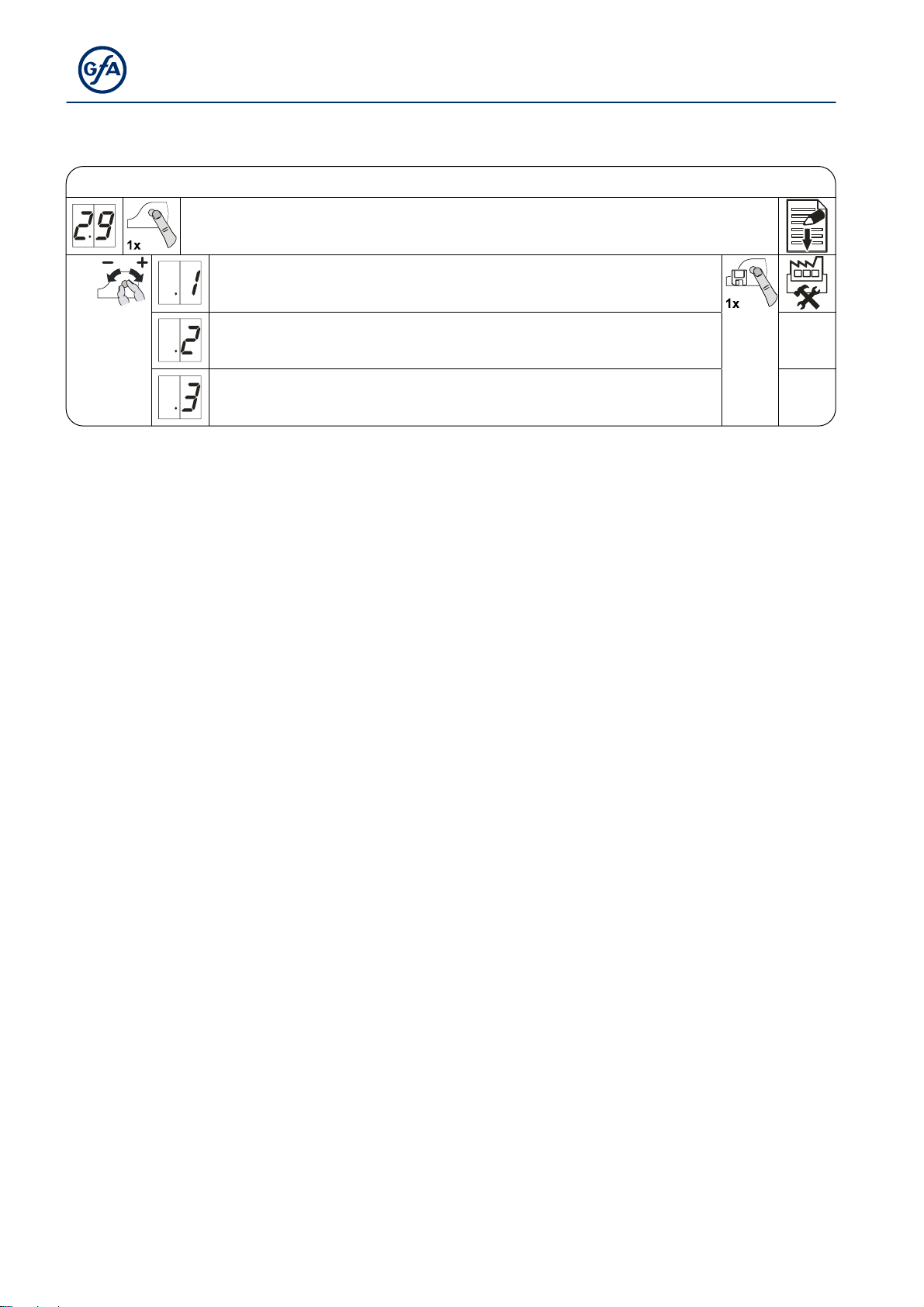
Door functions, part 4
Intermediate open function
All command inputs
Input X7.2 and
internal radio receiver
Input X5.3 and
OPEN push-button of control
24
Page 25
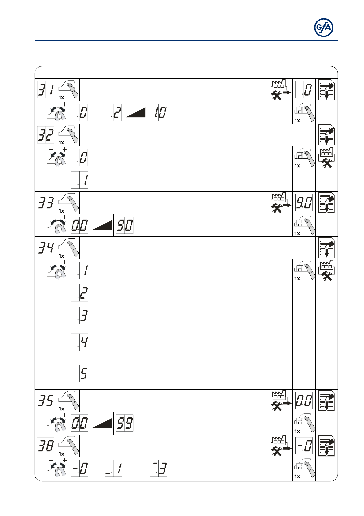
Safety functions
Force monitoring (DES)
Interruption of the photo cell function (DES)
Travel time monitoring (NES)
Safety functions
0 = Off
Adjustable for 2 % to 10 % overload
Off
On
(single reference position taught-in twice)
0 = Off
0 to 90 seconds
Door safety switch function
(Input X2.2 / WSD door-module)
Slack-rope or pass-door switch
Crash switch as NC contact
After activation: "Hold-to-run" door operating mode
Crash switch as NO contact
After activation: "Hold-to-run" door operating mode
Crash switch as NC contact
After activation: Reversing in OPEN final limit position.
Reset after contact reset otherwise "Hold-to-run" door operating mode
Crash switch as NO contact
After activation: Reversing in OPEN final limit position.
Reset after contact reset otherwise "Hold-to-run" door operating mode
Automatic opening
(Automatic closing menu item 2.3)
0 = Off
0 to 99 minutes
Reversing duration adjustment
[ + ] slower
[ – ] faster
25
Page 26
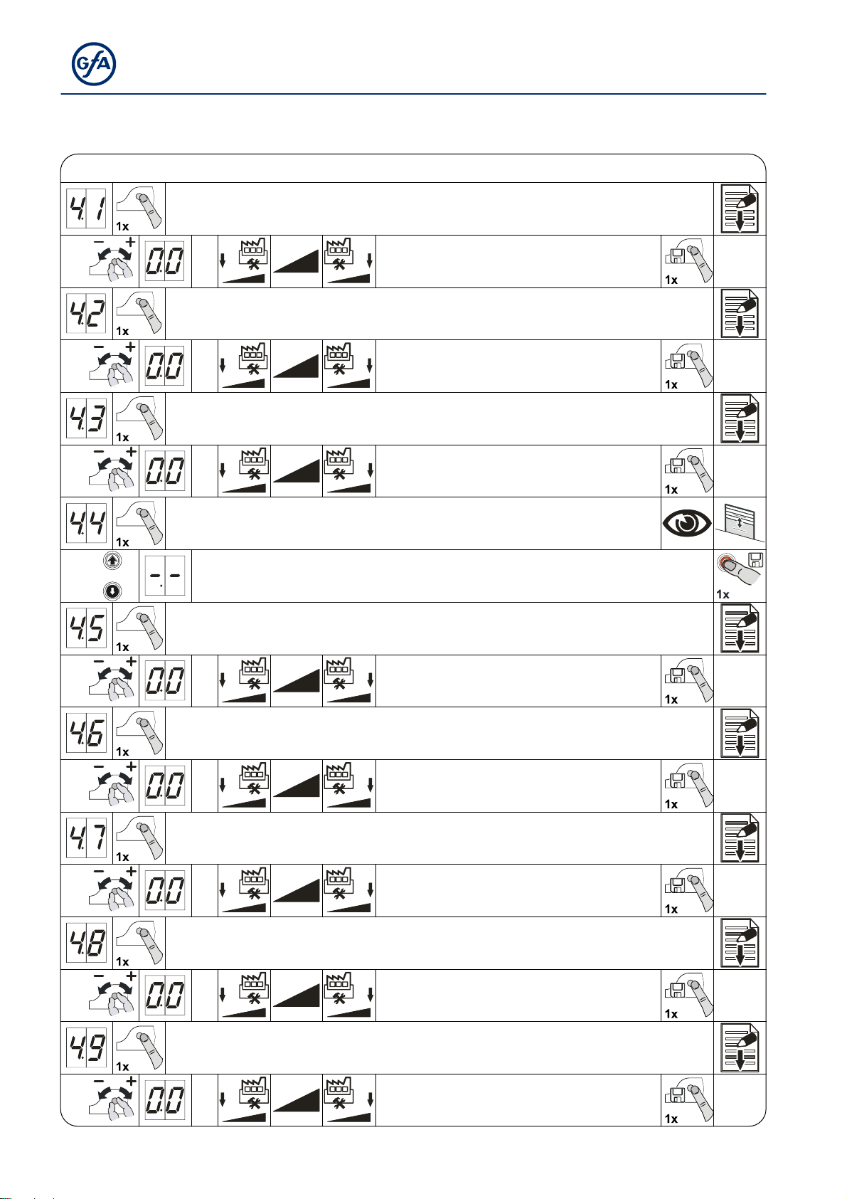
DI / FI settings
OPEN output speed
CLOSE output speed
Increased CLOSE output speed
Up to an opening height of 2.5 m
DI/FI settings
Output speed in rpm
Output speed in rpm
Changeover position to CLOSE output speed
(with adherence to minimum opening height requirement of 2.5 m!)
Approach and store desired door position
OPEN acceleration
CLOSE acceleration
OPEN deceleration
Output speed in rpm
0 = Off
DI Steps of 1.0 seconds
FI Steps of 0.1 seconds
DI Steps of 1.0 seconds
FI Steps of 0.1 seconds
CLOSE deceleration
OPEN/CLOSE crawling speed
26
DI Steps of 1.0 seconds
FI Steps of 0.1 seconds
DI Steps of 1.0 seconds
FI Steps of 0.1 seconds
Output speed in rpm
Page 27
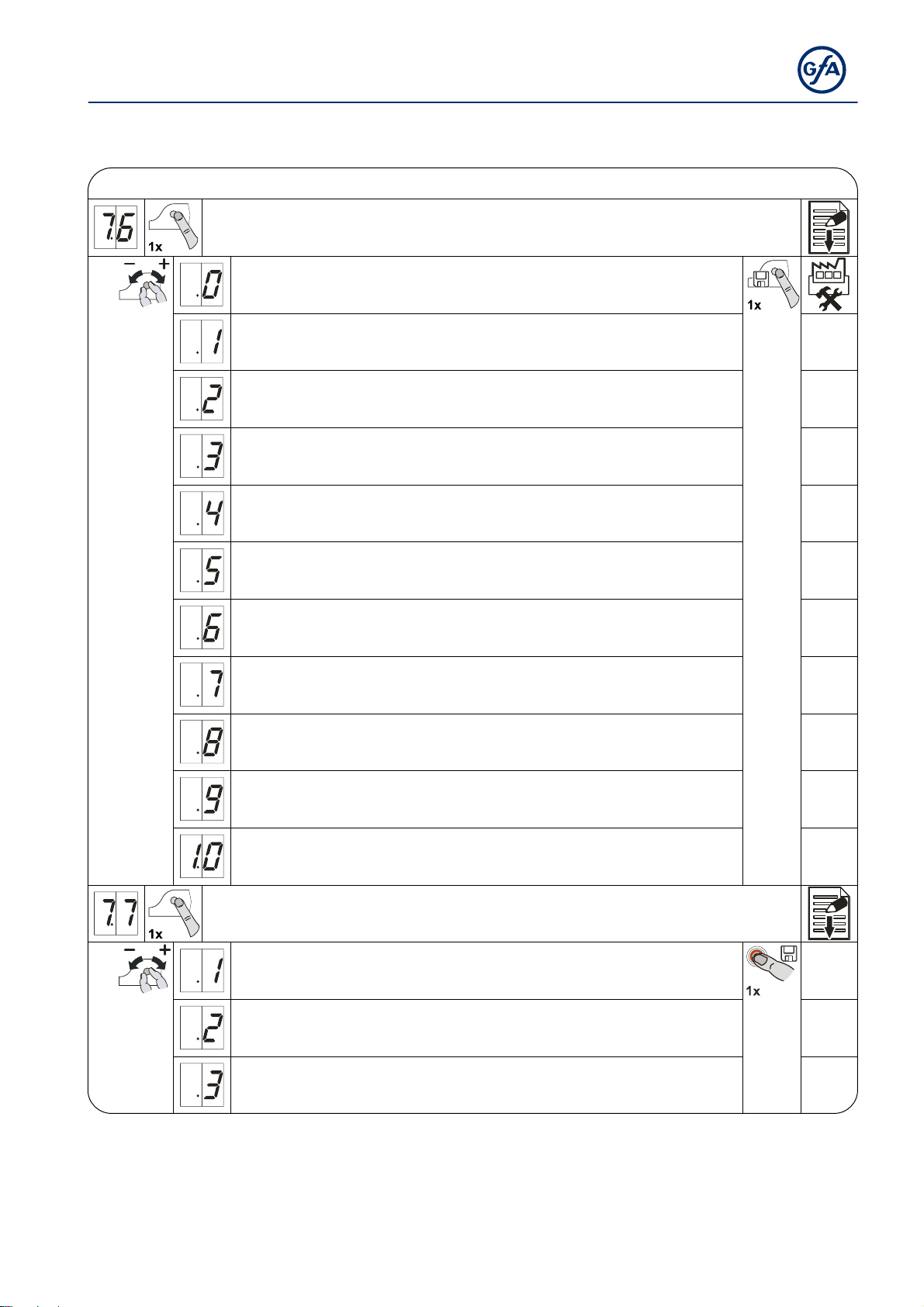
Extended door fu nctio ns
Extended door functions
Selection of radio transmitters manufacturer
(434 MHz)
Internal radio receiver deactivated
(Fixcode) GfA, Tedsen
Teleco "COD1"
-
(Rolling code of various providers) GfA UK, JCM, Dickert
(Fixed code) RDA
(Fixcode) TRL
-
-
-
-
Radio receiver function
Teach-in of a handheld transmitter
Cancellation of a taught-in handheld transmitter
Cancellation of all taught-in handheld transmitter
27
Page 28
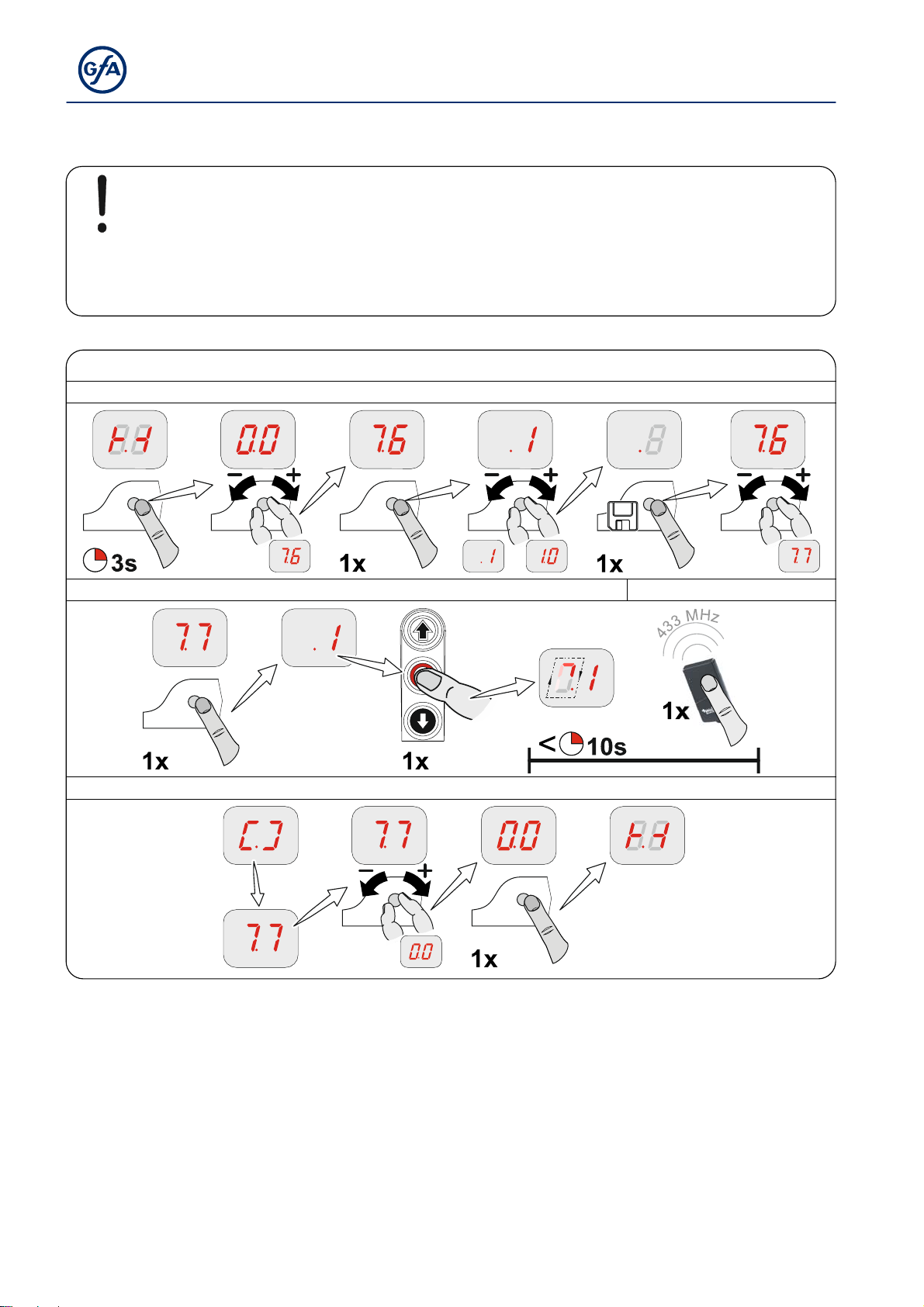
Teach-in of han dheld tr ans mitter
Note!
A combination of different radio transmitter manufacturers is possible
Only use 434-MHz handheld transmitters
Up to 64 radio channels can be taught.
Teach-in of handheld transmitter
1. Select radio transmitter manufacturer’s system
2. Activate radio receiver 3. Carry out teaching-in
4. Switch to door operation
28
Page 29
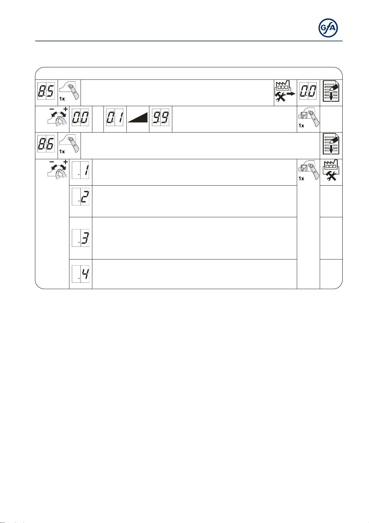
Maintenanc e cy cl e c oun ter
Maintenance cycle counter
Maintenance cycle preselection
01-99 corresponds to 1,000 to 99,000 cycles
Cycles are counted down
Reaction upon reaching zero
Status indication "CS" appears in turns with value set by menu item 8.5.
Changeover to "hold-to-run" door operating mode. Status indication "CS"
appears in turns with value set by menu item 8.5.
Changeover to "hold-to-run" door operating mode. Status indication "CS"
appears in turns with value set by menu item 8.5.
Option: Press STOP-button for 3 seconds to deactivate changeover and
status indications for 500 cycles.
Status indication "CS" appears in turns with value set by menu item 8.5
and relay contact X20 switches.
29
Page 30
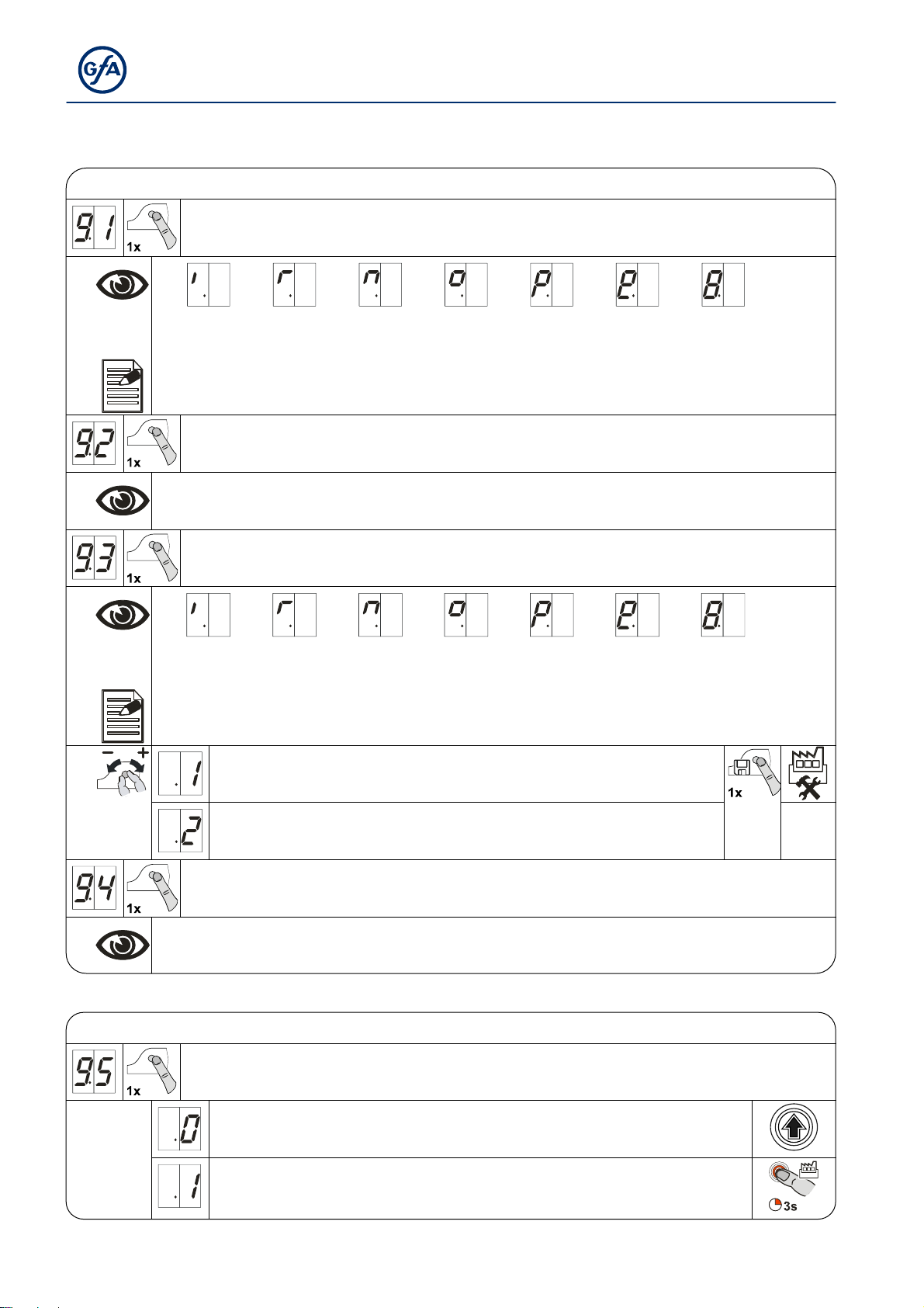
Readout of Data memory
Readout of Data memory
Cycle counter
7-digit number
Displayed in division of ten consecutively
M
HT = =
M
HT
1,000,000
100,000
ZT T H Z
ZT T == 10,000
1,000
HZ == 100
10
E = 1
E
Last faults
Display change of the last 6 faults
Data counter
7-digit number
Displayed in division of ten consecutively
M
HT = =
M
Cycle counter of the last change in programming
HT
1,000,000
100,000
ZT T H Z
ZT T == 10,000
1,000
HZ == 100
10
E = 1
E
Deleting of all settings
Number of activations of slack-rope, pass-door and crash switch
Software version
The firmware version of the control is displayed. Additionally the software version
of the motor is displayed for DI-drives and FI-drives.
Deleting
Deleting of all settings
Next input
All settings are set to factory setting!
Except for cycle counter
30
Page 31
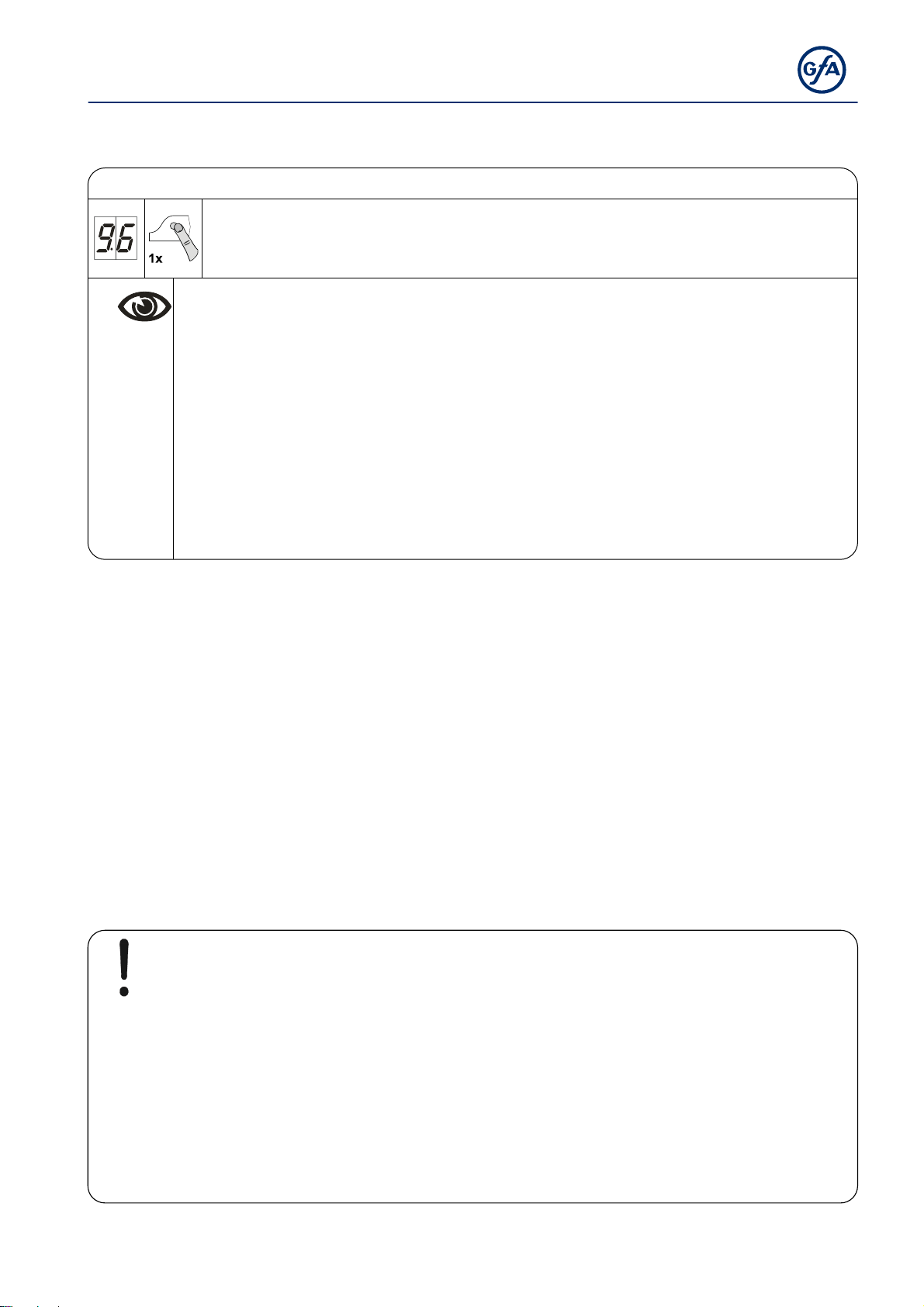
Reading out WSD door-module data
Reading out WSD door-module data
WSD door-module data
(Only activated at taught-in WSD door-module,
Displaying of missing data is done by „-.-.“)
Data indicated alternately
1. Version of master radio module
2. Type of safety edge
„0.0.“ = none
„0.1.“ = 1k2
„0.2.“ = 8k2
„0.3.“ = optic
3. Door safety switch
„0.0.“ = inactive
„0.1.“ = active
4. Battery voltage
5. Assigned / selected communication channel
6. Signal quality ranging from 0% - 99%
8 Safety devices
X2: Input, safety edge
The door control automatically detects three different safety edges to protect the closing
movement of the gate wing.
Electrical safety edge,
Pneumatic safety edge,
optical safety edge system.
Important!
▶ Connect safety edge systems in accordance with EN 12978
▶ Check position of S5 pre-limit switch on the safety edge (only for NES)
When the door is opened > 5cm, a reversing
must be executed if the safety edge has been activated
"Hold-to-run" door operating mode can always be used should the safety edge be
defective
31
Page 32
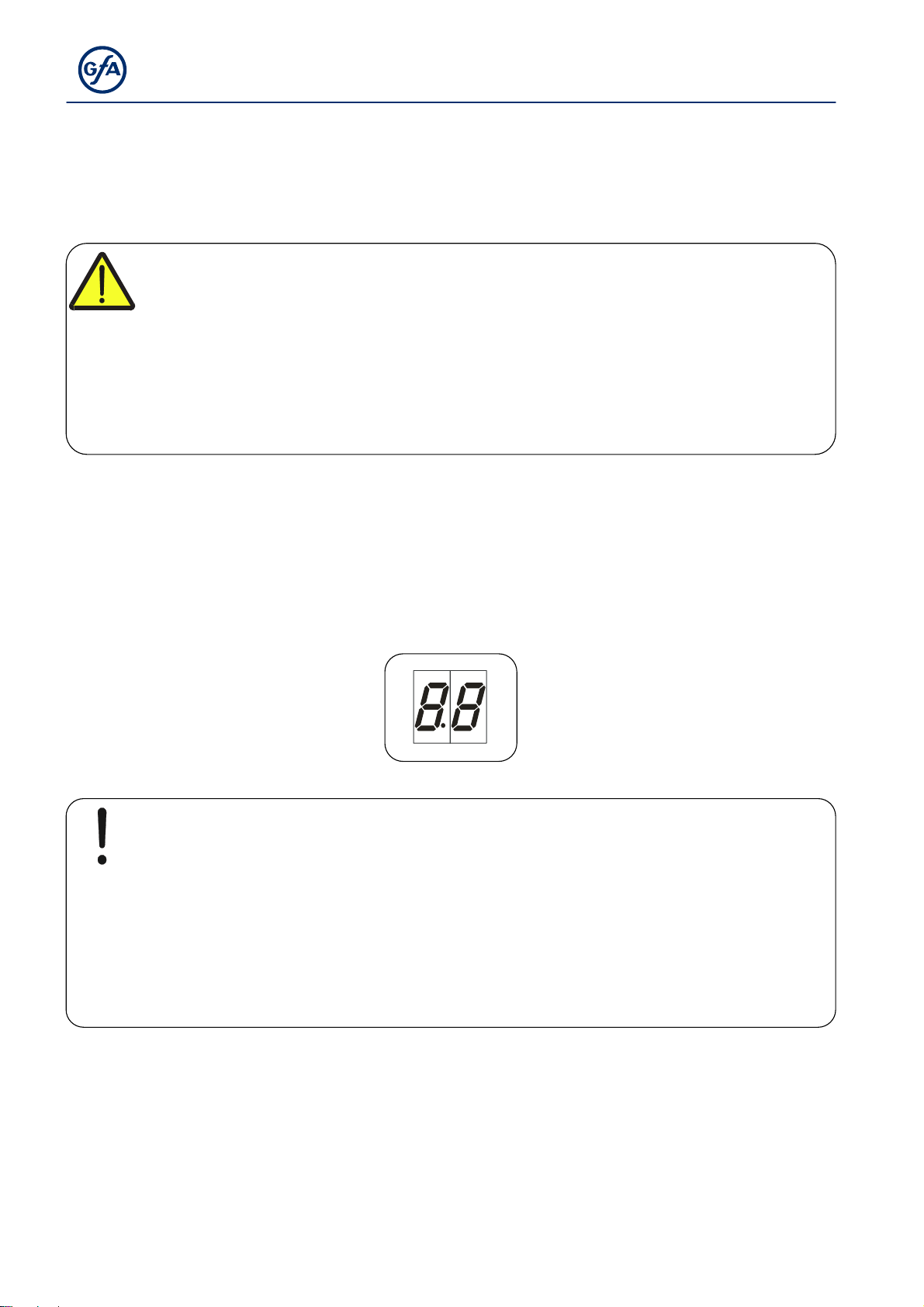
EMERGENCY operation
Warning!
▶ For EMERGENCY operation, the door has to be checked (it has to be in a fault-
free state)
“Hold-to-run” door operating mode:
The door must be fully visible from the operating point
EMERGENCY operation allows for moving the door to a required position by bypassing faults
with the signal transmission of the safety device.
EMERGENCY operation is activated after pressing the STOP push-button and holding for 7
seconds, and is indicated by the flashing display.
Note!
The door cannot be moved in case of “F1.3” and “F1.4” fault indications for
reasons of operating safety.
▶ Activation of EMERGENCY operation: Use the built in push button of the control
to press and hold the STOP-button while simultaneously pressing the OPEN or
CLOSE push-button to move the door
32
Page 33
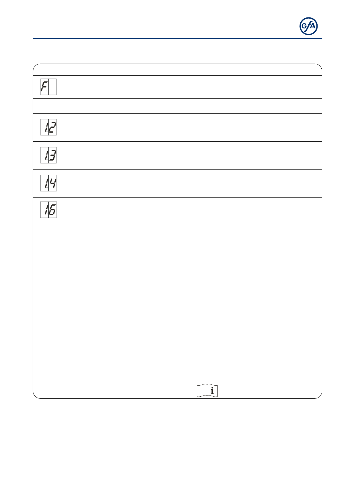
9 Status display
Faults
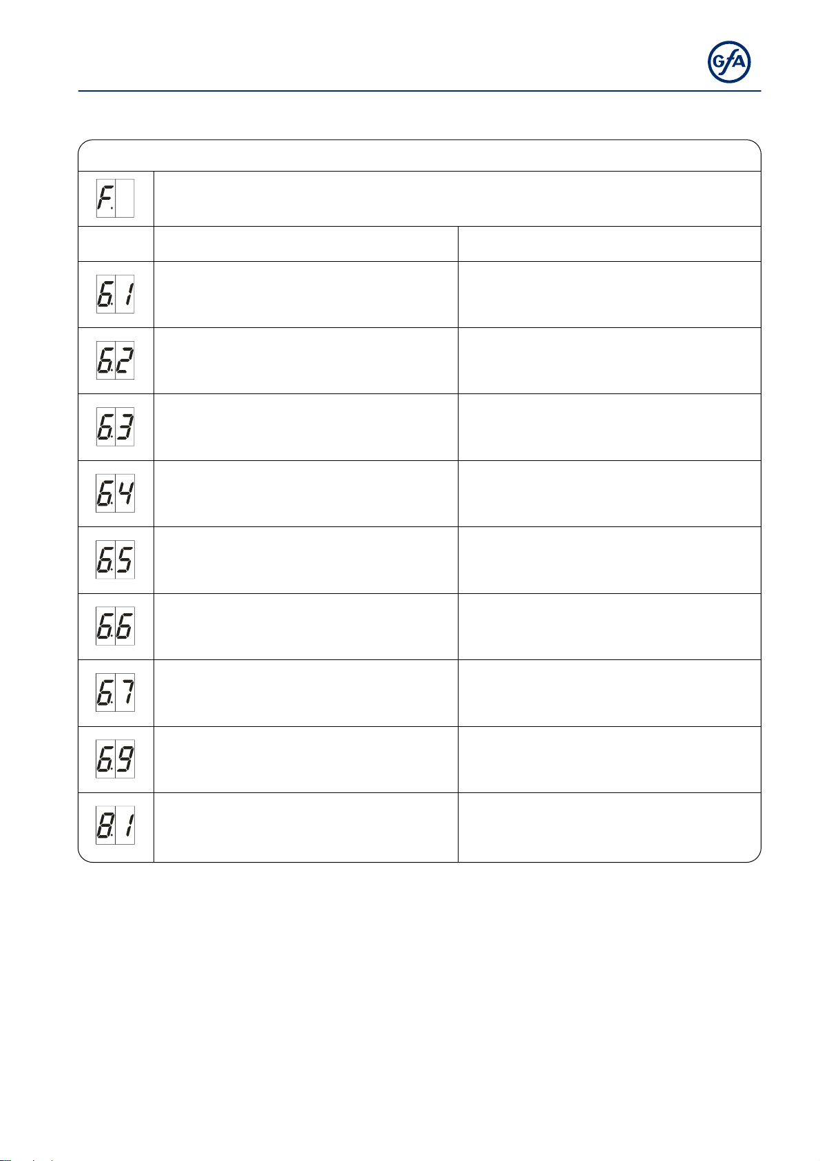
Faults
Display: "F" and code
Code Fault description Fault causes and fault correction
Terminals X2.1 – X2.2 are open.
Slack-rope switch/Pass-door contact is open.
Open safety circuit (DES)
Emergency manual operation has been
activated.
Thermal protection of the motor has tripped.
Terminals X3.1 – X3.2 are open.
Emergency stop has been activated.
Radio transmission of WSD door-module is
faulty.
Check door safety switch.
Check whether the connection cable is
connected.
Check emergency manual operation.
Check for overload or stalling of the drive unit.
Check emergency stop.
Check whether the connection cable is
connected.
Radio channel assigned twice:
Use menu item 9.6 to read off the radio
channel.
Moisture in WSD door-module:
Replace WSD door-module und use a splash
guard (optional equipment).
Obstacle between WSD door-module and
door control:
Adapt fitting configuration or use a spiral
cable.
Battery voltage too low:
Read off voltage value using menu 9.6 and
replace battery if this is less than 3.2 V.
Red LED in WSD door-module:
Press P1 push-button.
Flashing: Faulty radio connection
Lit: Radio connection OK
Pay attention to the WSD door-module
manual
33
Page 34
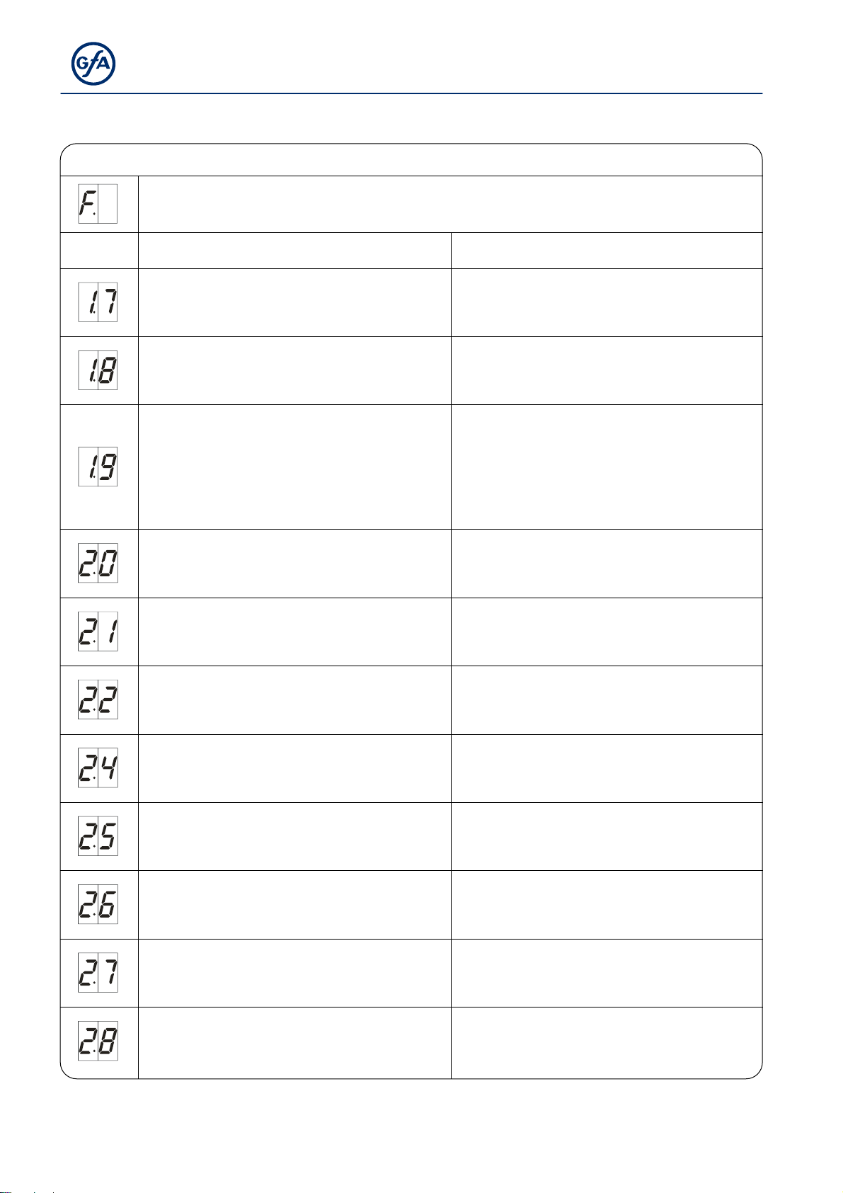
Faults
Display: "F" and code
Code Fault description Fault causes and fault correction
Faulty entrysense switch.
Contact resistances are too high.
Faulty entrysense installation.
Entrysense input
X2.1 – X2.2 is faulty.
WSD door-module batteries are too low.
No safety edge detected.
Terminals X6.1 – X6.2 are open.
Photo cell has been activated.
Maximum number of reversing movements for
door through safety edge system activation has
been reached.
(Only with automatic closing)
Activation of safety edge 8k2.
Safety edge 8k2 defective.
Activation of safety edge 1k2.
Safety edge 1k2 defective.
Open and close pass door.
Check resistance.
Check the pass door installation.
Switch control off and on.
Replace control if necessary.
Change batteries of the WSD door-module
If the battery service life was considerably less
than one year, check fault code 1.6 (radio
channels assigned twice, obstacles).
Check the wiring of the safety edge.
Check function of WSD door-module.
Check alignment of the photo cell.
Check connection cable.
Replace photo cell if necessary.
Obstacles along the door travel path.
Check whether the safety edge system is
correctly functioning.
Check whether the safety edge system is
correctly functioning.
Check whether the connection cable has shortcircuited.
Check whether the safety edge system is
correctly functioning.
Check whether the connection cable is
connected.
Check whether the safety edge system is
correctly functioning.
Check whether the connection cable is
connected.
Check whether the safety edge system is
correctly functioning.
Check whether the connection cable has shortcircuited.
34
1k2 testing is negative.
Testing is activated in the lower final limit
position.
Check pre-limit switch (with NES "S5").
Page 35
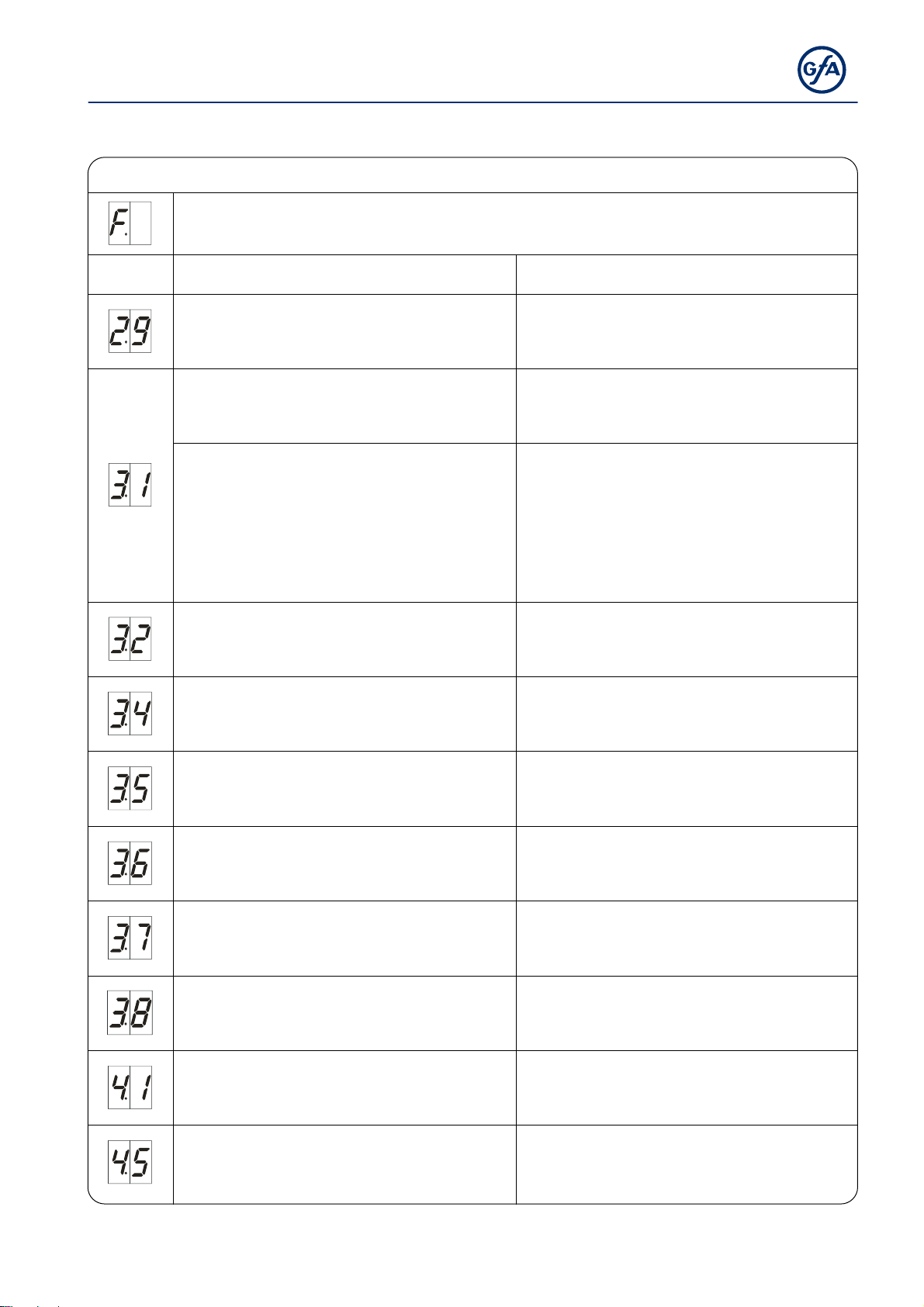
Faults
Display: "F" and code
Code Fault description Fault causes and fault correction
Wireles safety device of the WSD door-module
or optical safety edge system has been activated
or is defective.
(DES)
OPEN emergency stop switch reached.
(NES)
OPEN or CLOSE emergency stop switch
reached.
Emergency manual operation has been
activated.
Thermal protection of the motor has tripped
Limit switch system has changed over from NES
to DES without the control being reset.
(DES)
CLOSE emergency stop switch reached.
(NES)
Faulty activation of the “S5” pre-limit switch.
Check the WSD door-module.
Check whether the safety edge system is
correctly functioning.
In the voltage-free state, move the door back via
emergency manual operation.
Check OPEN/CLOSE emergency stop switch.
Check emergency manual operation.
Check drive unit for overload or stalling.
Reset of control via menu item "9.5".
In the voltage-free state, move the door back via
emergency manual operation.
Check the “S5” pre-limit switch for correct
functioning and setting.
No limit switch detected
(active at initial start-up).
Connect the limit switch to the control.
Check the limit-switch connection cable.
Limit switch system has changed over from DES
to NES without the control being reset.
Reset of control via menu item "9.5".
Internal plausibility error.
Execute fault clearance trough movement
command.
Internal control temperatur too high. Switch of control and let it cool down.
Triggering of force monitoring. Check the door mechanism for stiffness.
Check crash switch / connection cable.
Crash switch X2.1 – X2.2 is activated.
To reset fault: Press STOP-button and hold for 3
seconds.
35
Page 36
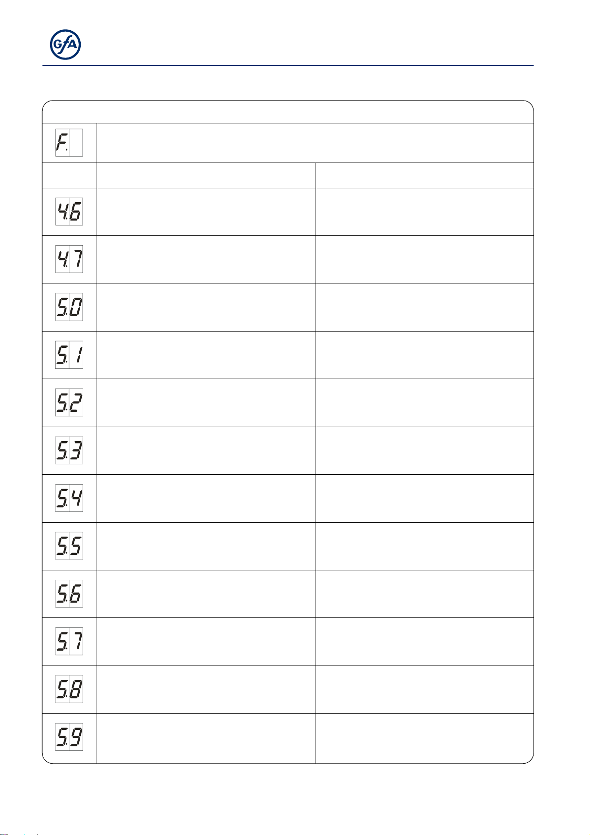
Faults
Display: "F" and code
Code Fault description Fault causes and fault correction
Terminals X6.1 – X6.2 are open.
Light curtain has been activated.
Light curtain defective.
Fault of the controller.
ROM error.
CPU error.
RAM error.
Check light curtain.
Check whether the connection cable is
connected.
Comply with the light curtain manufacturer’s
specifications.
Check connection cable.
Switch control off and on.
Replace control if necessary.
Switch control off and on.
Replace control if necessary.
Switch control off and on.
Replace control if necessary.
Switch control off and on.
Replace control if necessary.
Internal fault of control.
Fault of digital limit switch (DES)
Fault with door movement.
Fault with rotating direction. Change rotating direction via menu item “0.2”.
Unacceptable door movement in stopped state.
No compliance with specified travel direction at
drive unit.
Switch control off and on.
Replace control if necessary.
Check DES connector and connection cable.
Switch control off and on.
Check the door mechanism for stiffness.
Check the limit switches for correct rotational
movement.
Switch control off and on.
Execute fault clearance trough movement
command.
Check brake and drive unit.
Execute fault clearance trough movement
command.
Check for overload of the drive.
36
Page 37
y
Faults
Display: "F" and code
Code Fault description Fault causes and fault correction
DI / FI closing speed is too high.
Internal FI communication fault.
Low voltage in the DC voltage sink.
Excess voltage in the DC voltage link.
Temperature limit exceeded.
Permanent current overload.
Brake / FI fault.
Collective indication for FI.
Switch control off and on.
Replace drive unit if necessary.
Switch control off and on.
Replace FI drive unit if necessary.
Execute fault clearance trough movement
command.
Check mains input voltage.
Change slope durations/speeds.
Check mains input voltage.
Execute fault clearance trough movement
command.
Change slope durations/speeds.
Check for overload of the drive unit.
Cool down the drive unit and reduce the number
of cycles.
Check for overload of the drive unit.
Check the door mechanism for stiffness or
weight.
Check brake; replace if necessary.
If problem recurs, replace drive unit.
Execute fault clearance trough movement
command.
Replace drive unit if message is continually
displa
ed.
At initial operation minimum travel distance was
not completed.
Move the door for at least 1 second.
37
Page 38
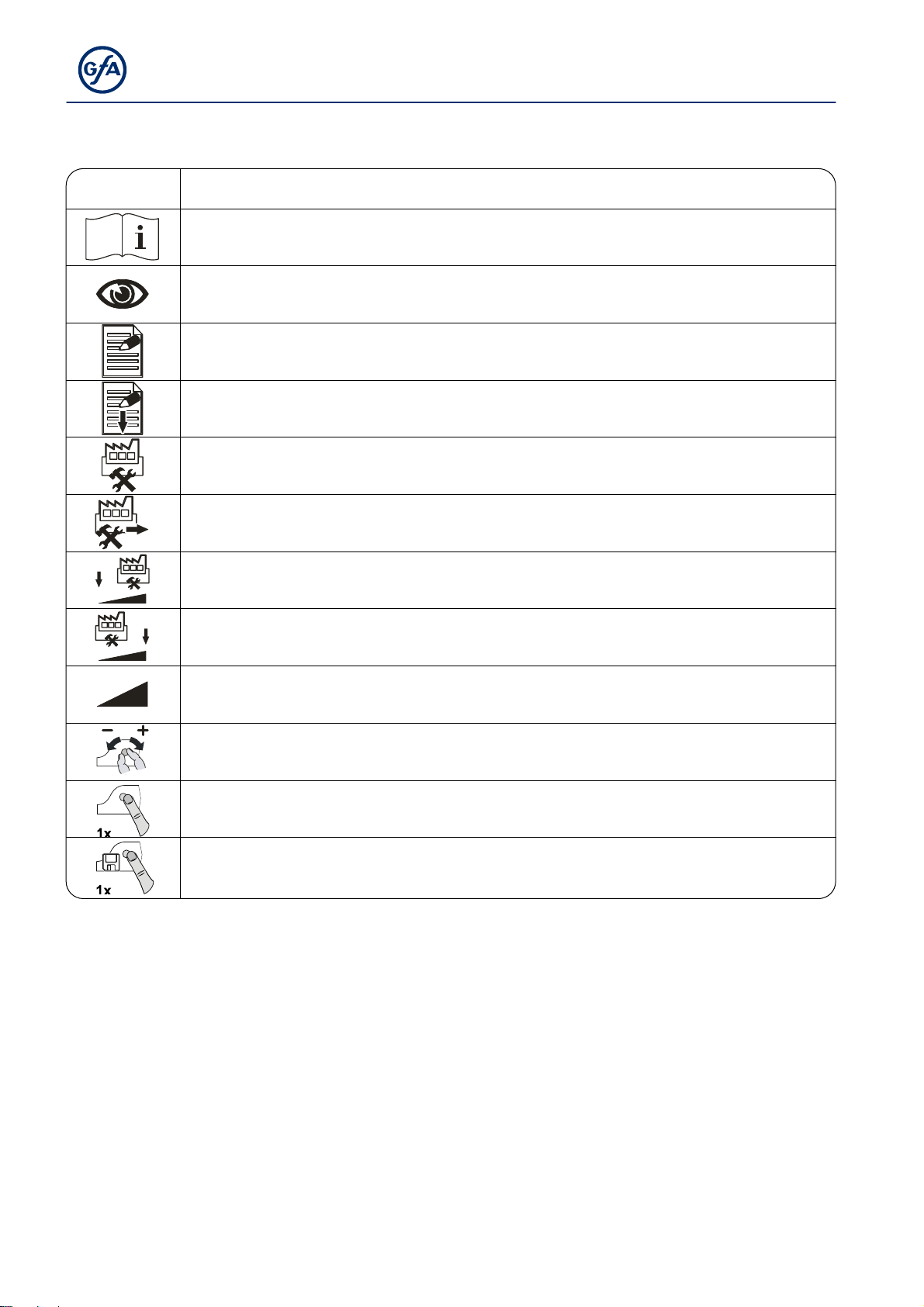
10 Explanation of symbols
Symbol Explanation
Prompt: Read installation instructions
Prompt: Check
Prompt: Note
Prompt: Note the setting of the menu below
Factory setting of the menu
Factory setting of the menu, value on the right
Factory setting of the minimum limit, dependent on drive unit
Factory setting of the maximum limit, dependent on drive unit
Setting range
Prompt: Select menu item or value,
turn selector switch to the left or to the right
Prompt: View menu item,
press selector switch once
Prompt: Store,
press selector switch once
38
Page 39
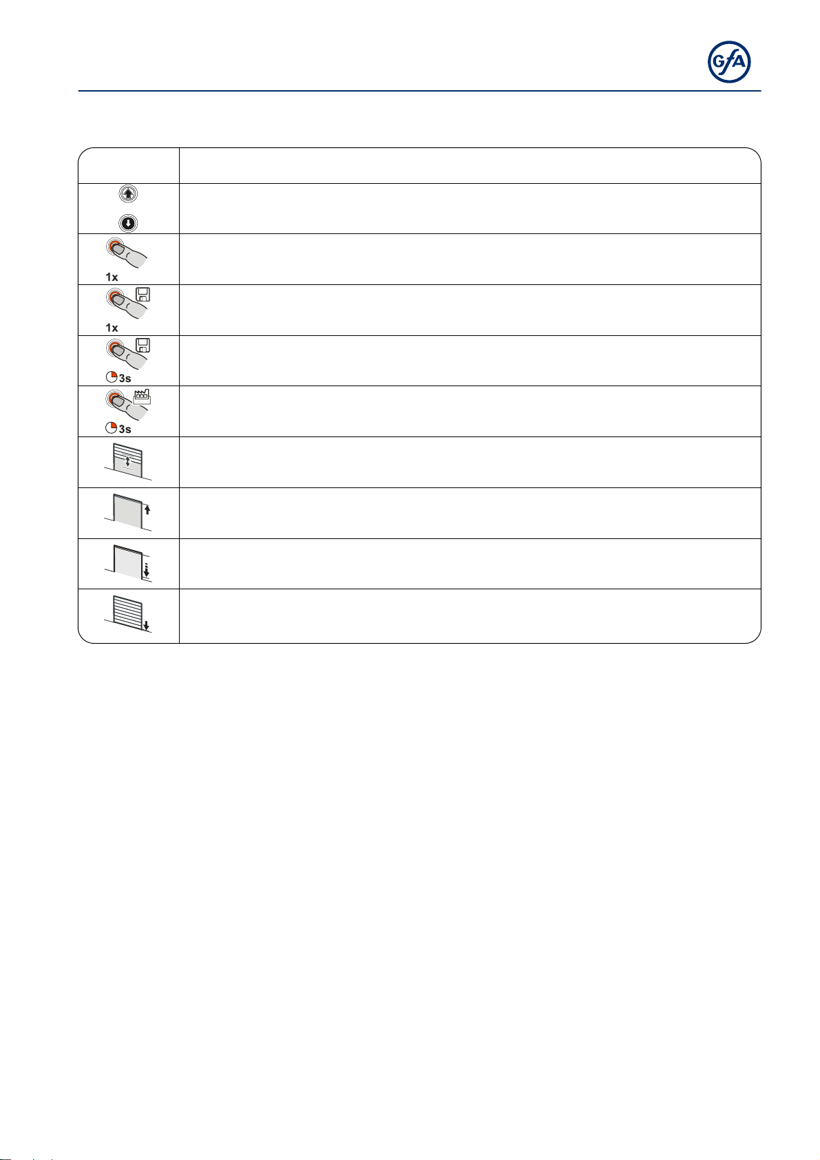
Symbol Explanation
Prompt: Setting via OPEN/CLOSE built in push-button;
Use OPEN push-button to increase value, CLOSE push-button to decrease value
Prompt: Press stop button once via built in push-button
Prompt: Save,
press stop button once via built in push-button
Prompt: Save,
press stop button for three seconds via built in push-button
Prompt: Reset the control,
press stop button for three seconds via built in push-button
Prompt: Move to door position
Prompt: Move to door position for OPEN final limit position
Prompt: Move to pre-limit
Prompt: Move to door position for CLOSE final limit position
39
Page 40
11 Decl arati on of Inc orporati on/De clar ation of Co nfor mity
Declaration of Incorporation
pursuant to Machinery Directive 2006/42/EC for a partly
completed machine Appendix II Part B
Declaration of Conformity
pursuant to EMC Directive 2004/108/EC
We,
GfA ELEKTROMATEN GmbH & Co. KG
hereby declare that the product specified in the following complies with the above-mentioned EC
Directive and is only intended for installation in a door.
TS 971
Applied standards
DIN EN 12453
Doors – Safety in use of power operated doors
DIN EN 12978
DIN EN 60335-1
DIN EN 61000-6-2
DIN EN 61000-6-3
Safety devices for power operated gates and doors
Safety of electrical devices for the use in the household and similar
purposes– Part 1: General requirements
Electromagnetic compatibility (EMC) – Part 6-2 Generic standards –
Immunity for industrial environments
Electromagnetic compatibility (EMC) – Part 6-3 Generic standards –
Emission standard for residential, commercial and light-industrial
environments
On reasoned request, we undertake to submit the special documents for this partly completed
machine to the supervisory authorities.
Authorised representative for the compilation of the technical documentation
(EU address in the company)
Dipl.-Ing. Bernd Synowsky
Documentation representative
Partly completed machinery according to EC Directive 2006/42/EC is only intended to be installed
in, or combined with, other machinery (or other partly completed machinery/systems) to form a
completed machine pursuant to the Directive. Therefore, this product may be put into operation
only when it has been determined that the complete machine/system in which it has been installed
complies with the provisions of the above-mentioned directives.
Düsseldorf, 01.12.2014
Managing Director Signature
40
Stephan Kleine
 Loading...