

Page 1
Multiuser receiver
433/500
Installation
Manual
We appreciate your choice of a product GfA ELEKTROMATEN UK Ltd.
This product is addressed to manage the access in
automatic door control systems
This appliance GfA ELEKTROMATEN UK Ltd has been carefully manufactured and
checked
GfA ELEKTROMATEN UK Ltd has designed this system to assure the best rielability
and satisfaction
in the time
Type. 40018505 00001-EVR/R500
Page 2
Important recommendations
0Never interfere with the product when connected
to a power source;
0Avoid direct contact with water;
0Regularly check the state of the product;
0Respect the current norms;
0Wear protected glasses to avoid injury during the
drilling phase;
0 Chance the factory code;
General remarks
! Radio
The materials and the technology used have made it
possible to create a system functioning on the 433,05 434,790 MHz frequency band, used by LPD equipments
and therefore subject to european radio and
electromagnetic compatibility regulations (CE).
! Rolling Code
In order to guarantee your safety and the total
inviolability of the communication between transmitter
and receiver, the code sent out by the transmitter
changes every time the equipment is used and is
recognised by the receiver only, thanks to an
unfalsifiable code-setting calculation. The system thus
conceived avoids all risk of being recording or of the
code being copied (268 million combinations).
Composition of the receiver
See fig. 1 of the enclosed “Installation phases”
Item Description Q.ty
1 Receiver 1
2 Antenna wire 1
3 Assembly screws 4
4 Plugs 4
Characteristics
! Receiver
Local oscillator freq. 6,6128 MHz
Power supply 12/24 Vac/dc
Modulation AM/ASK - FM/FSK
Number of memorizable users 507
Number of relays 2
Type of output contact 1 NO, 1 NO/NC
Commutable power 24 VA
Maximum relay voltage 60 V
Absorbtion 95 mA (relay excited)
Housing protection IP 40
Operating temperature from -10°C to +55°C
Dimensions (Fig 1) 180x140x68mm
Weight 330gr
! Transmitter
Frequency 433,92 MHz
Power supply 12 Vdc
Modulation AM/ASK
Number of functions 2 or 4
Coding type Rolling Code
Number of combinations
E.r.p. 100 - 200 µW
Absorbtion 18 mA
Range in open space with
receiver with antenna 100-200 meters
Operating temperature -10°C to +55°C
Dimensions 82x48x16 mm
Weight 32gr
Battery type Alkaline - 23A
Pag. 2
Receiver Transmitter
EVR/R500 VR/TF2E 2 Channel
( AM/ASK) VR/TF4E 4 Channel
EVR/TMASTER 2 Channel MASTER
Compatibility
The receiver can operate correctly with the corresponding
transmitters according to following table:
Declaration of Conformity
Hereby, CDVI Wireless Spa, declares that the radio equipment
type EVR/R500 is in compliance with directive 2014/53/EU. The
full text of the EU declaration of conformity is available at the
following internet address: www.gfa-elektromaten.co.uk
Page 3

Description
! Receiver
( See fig. 1 of the enclosed “Installation phases”).
It authorizes between 1 and 500 users (two buttons of a
transmitter correspond to a zone of use).
Possibility of memorizing 7 master transmitters.
2 relays available in series (1 NA contact, 1 NA or NC
contact) LCD back-lit visualization with two lines of 16
characters for clear messages.
! Master Transmitter (See. Figure 2 ).
Silver Transmitter with 2 yellow buttons
Function of the buttons.
Press both buttons simultaneously:
to enter the programming mode.
The left-hand button (channel A) is used :
! for normal functioning;
! to reply NO to a question from the receiver in the
programming phase;
! to move through the numbers 0 to 9 on the receiver
during the programming phase.
The right-hand button (channel B) is used:
! for normal functioning;
! to reply YES to a question from the receiver during
the programming phase;
! to conferm the choice or a number on the receiver
during the programming phase.
! User Transmitter ( See. Figure 2.)
Grey Transmitter with yellow push-buttons( basic version).
Available in 2-channel AB or 4-channel ABCD versions
Allows the transmitter to function normally
GfA ELEKTROMATEN UK Ltd advice
!
the pre-forated parts (fig. 4) situated at the back of
the receiver with the aid of a screwdriver.
! Make a hole in the pre-forated parts ( 5) (fig. 6).
! Put the plugs in the holes (fig. 7) or adapt the holes
to the nature of the support.
! Fix the receiver using the screws supplied (fig. 8).
! Make holes in the guiding slits (only in those used),
! Proceed to the electric connection (fig. 10), and
thread the wires through the guiding slits (fig. 9).
advice
When assembling the equipment outdoors, we advise you to
protect the receiver in a container with an IP54 level of protection.
Electrical connection
GfA ELEKTROMATEN UK Ltd advice
2
A telephone wire (0.6 mm ) is sufficient for the input of the receiver
and the relay cabling.
Receiver power supply:
- connecting clip 3: 0V
- connecting clip 4: 12/24 Vac/dc
Connect the output contacts:
- connecting clip 5: common relay 1
- connecting clip 6: NO contact relay 1 (contact normally open)
- connecting clip 7: common relay2
- connecting clip 8: NO contact relay 2 (contact normally open)
- connecting clip 9: NC contact relay 2 (contact normally closed)
Connect the antenna
- connecting clip 1: antenna conductor or antenna wire supplied with
the receiver
- connecting clip 2: braided wire of the antenna cable
Position the receiver on a plane, open it and remove
GfA ELEKTROMATEN UK Ltd
Pag. 3
The place in which the receiver is installed is very
important in order for the system to function well. The
following conditions must be respected:
- install the receiver far from all sources of disturbance like
computer systems, alarm systems, large magnetic fields,
radio emissions;
- the distance between two receivers must be at least 1.50
metres.
GfA ELEKTROMATEN UK Ltd advice
The installation and positioning of the antenna are fundamental
for good reception. Carry out tests before fixing the antenna
definitively. Place the antenna as high as possible and far from all
types of metal structures which could shield the receiving part of
the antenna.
Installation
Page 4
TRANSMITTER MASTER Nº 2
GfA 433/500
Transmitter
Master Nº 1
US: 501 RL:1/2 KY: A
STORE MASTER?
Transmitter
Master Nº 1
Transmitter
Master Nº 1
EXECUTED OK
MORE ...
Transmitter
Master Nº 2
Transmitter
Master Nº 1
US: 502 RL:1/2 KY: A
STORE MASTER?
Transmitter
Master Nº 2
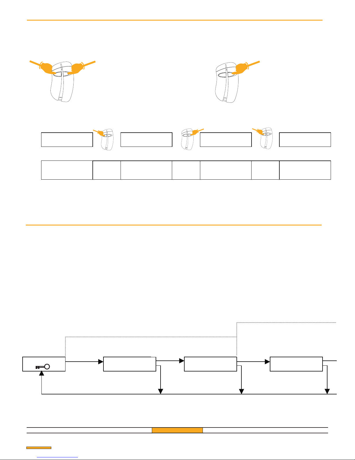
TRANSMITTER MASTER Nº 1 MEMORIZATION
Master transmitter memorization
This menu is accessible with the Master transmitter not
memorized and the default access code (11111). The
master transmitters are used to introduce the
parameters of the receiver and have to be memorized
as indicated above. It is possible to memorize up to 7
master transmitters on the same receiver.
advice
Memorize at least 2 master transmitters. If the first transmitter is
lost, the second will allow access to the parameters.
GfA ELEKTROMATEN UK Ltd
Function and use of the Master Transmitter
! Enter the programming mode and return to
the beginning of the current menu
! Reply YES to a question
Press the 2 buttons simultaneously
Example for the number change
STORE USER
USER Nº 001
The receiver indicates
The transmitter 001
1 pulse
on
NO
STORE USER
USER
Nº 0 0 2
The receiver indicates 002
The units have been confirmed
STORE USER
USER Nº 0 0 2
STORE USER
USER Nº 0 1 2
The receiver indicates
The transmitter 002
1 pulse
on
YES
1 pulse
on
YES
The receiver indicates
the transmitter 012
Pag. 4
Press the right-hand button
NO
YES
YES
NO+YES
NO
NO
YES
NO
YES
NO+YES
Page 5
US: 507 RL:1/2 KY: A
STORE MASTER?
Transmitter
Master Nº 7
EXECUTED OK
MORE ...
Transmitter
Master Nº 2
Transmitter
Master Nº 7
US: 507 RL:1/2 KY: A
EXECUTED OK
Transmitter
Master Nº 2
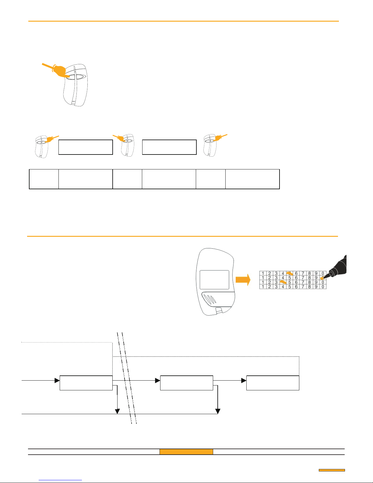
TRANSMITTER MASTER Nº 7 MEMORIZATION
MEMORIZATION
Transmitter
Master Nº 7
! Change a number or a letter
Some phases of parametre variation require the
visualization of numbers or letters. In these phases the
left-hand button of the master transmitter is used to
change the numbers from 0 to 9, and the right-hand
button is used to confirm the choice of numbers.
See the following example: positioning to User zone N.
412.
1 pulse
on
YES
STORE USER
USER
Nº 0 1 2
The receiver indicates the
transmitter 4 1 2
STORE USER
USER Nº 4 1 2
The receiver indicates 0 1 2
The tens have been confirmed
4 pulses
on
NO
1 pulse
on
YES
The hundreds have
been confirmed
advice
After memorizing the transmitters, we advise you to
proceed to number them with an indelible pen.
Example: transmitter memorized on field No. 504.
GfA ELEKTROMATEN UK Ltd
Pag. 5
! Reply NO to a question
Press the left-hand button
Exit from the menu
NO
YES
NO
NO+YES
YES
NO
Page 6
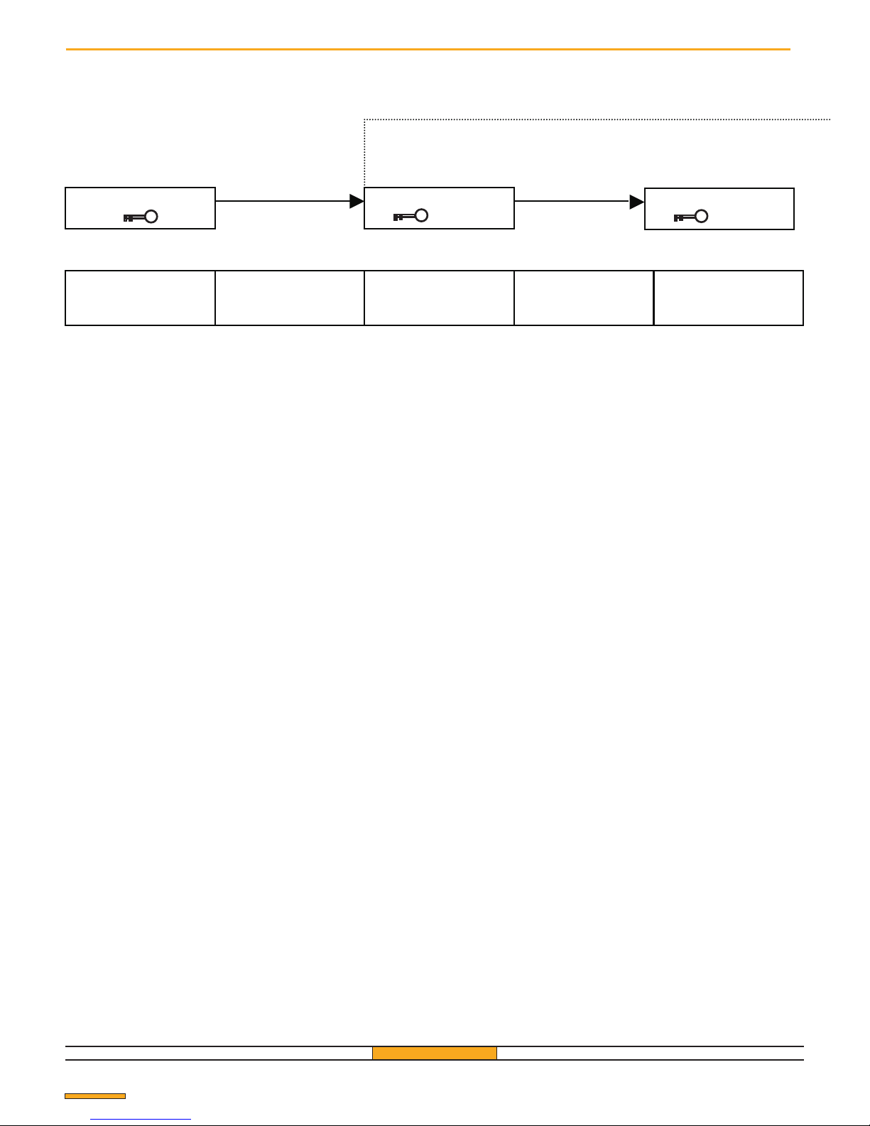
Entry into the main menu
*.Personalize the access code (see "Change a number
or a letter" p. 5).
GfA 433/500
Welcome message
MENÚ
0 0 0 0 0
Transmitter
Master Nº 1
Press on both keys of a
Master transmitter
(simultaneously )
Dial the default key or the
personal key using the
Master transmitter
Activate the key YES
of the
Master transmitter
The default or personal key
has been set
MENÚ
1 1 1 1 1
Transmitter
Master Nº 1
ACCESS CODE SETTING
Pag. 6
YES
NO+YES
The default access code is 11111.
It is a good idea to personalize this code by choosing
one of the 65536 possible combinations, to prevent
unauthorized personnel from access and from being
able to interfere with the parameters of the system.
Page 7
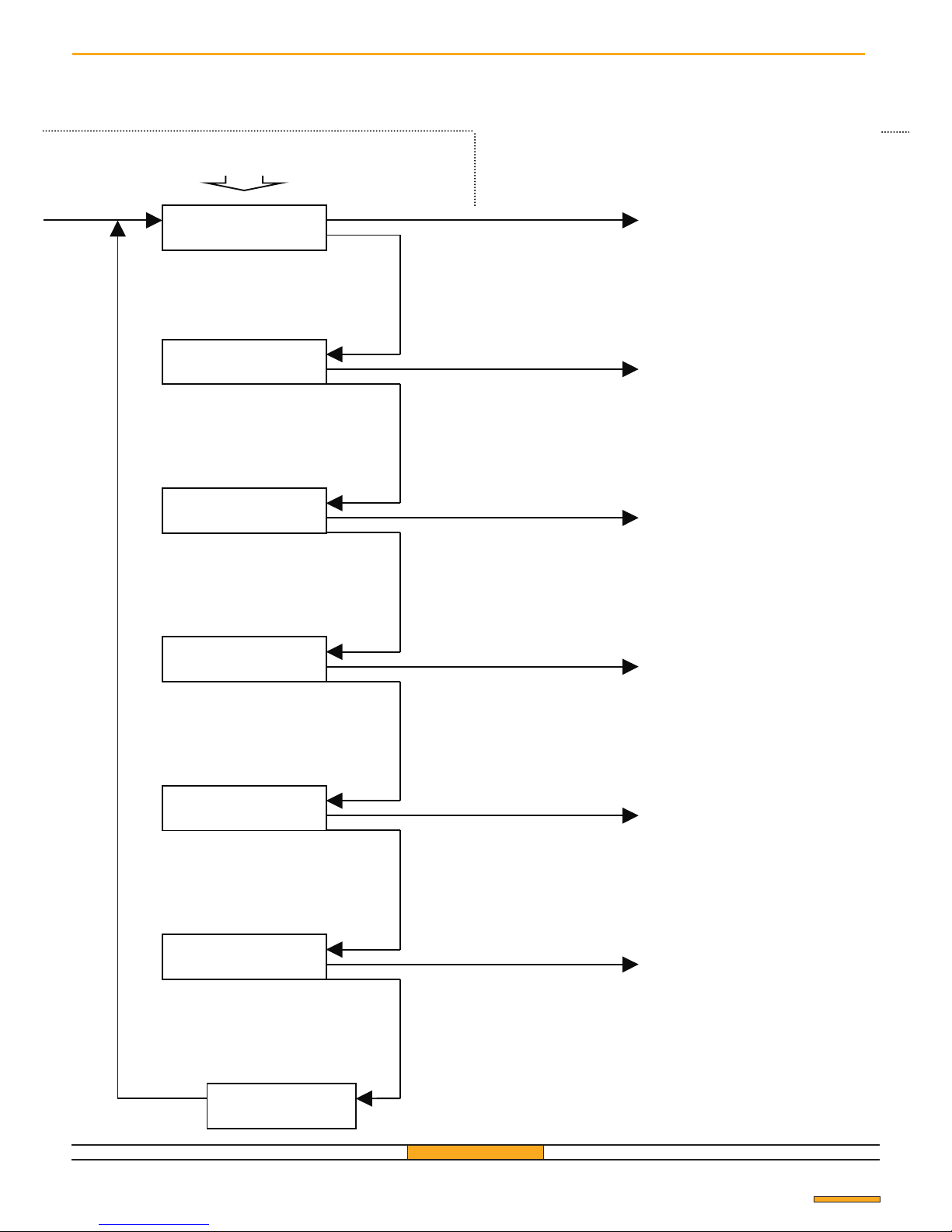
MENU
STORE USER ?
Transmitter
Master Nº 1
Next menu:
“STORE USER”
(pag. 7).
Master Nº 1
MENU CHOICE
MAIN MENU
Transmitter
Master Nº 1
MENU
CONFIG. RECEIVER ?
Next menu:
“CONFIG. RECEIVER”
(pag. 10).
Master Nº 1
Transmitter
Master Nº 1
MENU
MODIFY USER ?
Next menu:
“MODIFY USER”
(pag. 12).
Transmitter
Master Nº 1
Transmitter
Master Nº 1
MENU
DELETE ?
Next menu:
“DELETE”
(pag. 14).
Transmitter
Master Nº 1
Transmitter
Master Nº 1
MENU
COPY ?
Next menu:
“COPY”
(pag. 16).
Transmitter
Master Nº 1
Transmitter
Master Nº 1
MENU
EXIT ?
Back to the welcome message
Transmitter
Master Nº 1
Transmitter
Master Nº 1
Back to menu
“STORE USER”
Pag. 7
Transmitter
Transmitter
YES
YES
YES
YES
YES
YES
YES
NO
NO
NO
NO
NO
NO
Page 8
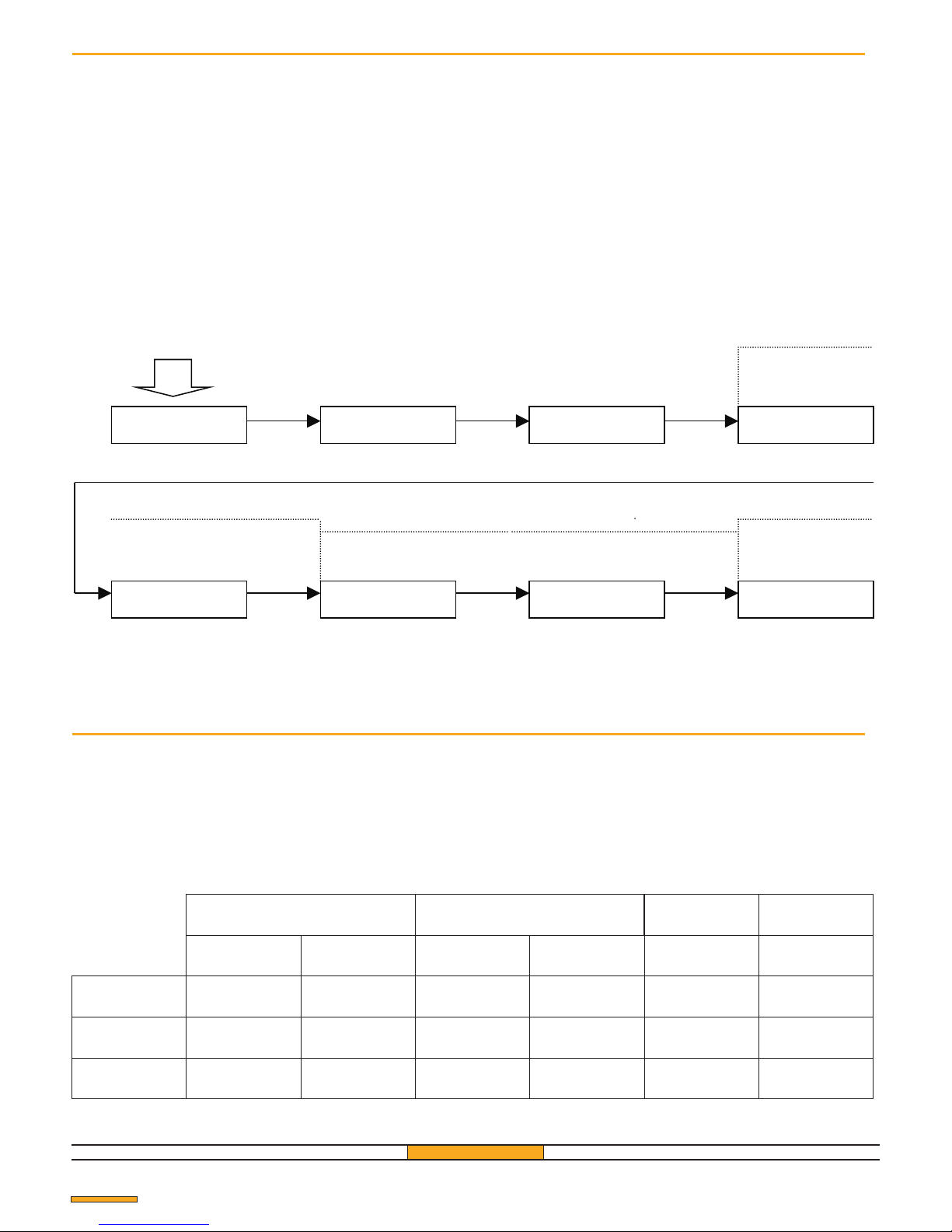
Transmitter
Master Nº 1 Master Nº 1 Master Nº 1
* *
Nº 2
Nº 3
Nº 3
TRANSMITTER N° 2 MEMORIZATION
MENU
STORE USER ?
STORE USER
USER Nº 001
USER Nº 001
RELAY: ½ KEY: A
USER Nº 001
START PROG ...
See
“ENTRY INTO THE MAIN MENU”
US: 002 RL: ½ KY: A
STORE USER ?
EXECUTED OK
MORE ....
UT: 003 RL: ½ TA : A
STORE USER ?
EXECUTED OK
MORE...
TRANSMITTER N° 2 MEMORIZATION
Pag. 8
Memorization of the User transmitters
The receiver will memorize the first transmitter in the
following way:
- USER n. 001: the transmitter will be memorized in
position 001;
- RELAY 1/2: the transmitter will control relays 1 and 2
of the receiver;
- KEY A: button A of the transmitter will control relay 1
of the receiver and button B relay 2.
Each of these parameters can be modified. See "Change
a number or a letter" (p. 5) and "Modify relay or key
parameters" (p. 8).
GfA ELEKTROMATEN UK Ltd
Before memorizing the transmitters, we advise you to number
them, marking each one with an indelible pen. For
example:transmitter to memorize on Position n. 348.
Advice
Choice of “RELAY” or “CHANNEL” parameters
For every transmitter the receiver offers:
- a position to memorize;
- the relay or relays which will be activated by the
transmitter;
- the channel or channels used by the transmitter.
The table below show the correspondences between
what appears on the display and the setting of the
transmitter buttons on the receiver relays.
Relay 1/2
Relay 1
Relay 2
Channel A
Channel B
Channel C Channel D
A on relay 1
B on relay 2
A 1
B on relay 2
on relay
B 1
C on relay 2
on relay
C 1
D on relay 2
on relay
D 1
A on relay 2
on relay
A 1on relay
A 1on relay
A 2on relay
A 2on relay
TX 2 keys TX 4 keys
TX 2 keys TX 4 keys
B 1on relay
B 1on relay
B 1on relay
B 2on relay
B 2on relay
TX 4 keys
TX 4 keys
C 1on relay
D 1on relay
C 2on relay
D 2on relay
Transmitter
Transmitter Transmitter
Transmitter
Transmitter
YES
YES YES
YES
NO+YES
NO+YES
Page 9
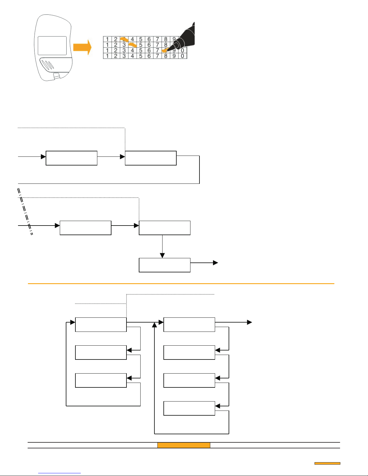
Advice
The receiver is programmed in the factory with a default
access code of 11111. To facilitate the memorization of
the tranmitters, it is advisable to modify the access code
by entering the code "00000". After having memorized
the transmitters, it is a good idea to change the access
GfA ELEKTROMATEN UK Ltd
Transmitter
Nº 1
Nº 1
Nº 2
Nº 50
Nº 50
Nº 50
TRANSMITTER N° 1 MEMORIZATION
Nº 50
US: 001 RL: ½ KY: A
STORE USER?
EXECUTED OK
MORE .......
Back to the welcome
Message
US: 050 RL: ½ KY: A
STORE USER?
TRANSMITTER N° 50 MEMORIZATION
EXECUTED OK
USER Nº 001
Exit
USER Nº 001
RELAY: ½ AKEY:
MODIF. RELAY
USER Nº 001
RELAY: KEY: 1 A
USER Nº 001
RELAY: KEY: 2 A
USER Nº 001
RELAY: KEY: 1 A
USER Nº 001
RELAY: KEY: 1 B
USER Nº 001
RELAY: KEY: 1 C
USER Nº 001
RELAY: 1 KEY: D
MODIF. CHANNEL
Pag. 9
Transmitter Transmitter
Transmitter
Transmitter
EXECUTED OK
MORE .......
Transmitter
Transmitter
NO+YES
YES
NO+YES
NO+YES
YES
NO
NO+YES
YES
YES
NO
NO
NO
NO
NO
NO
NO
Page 10
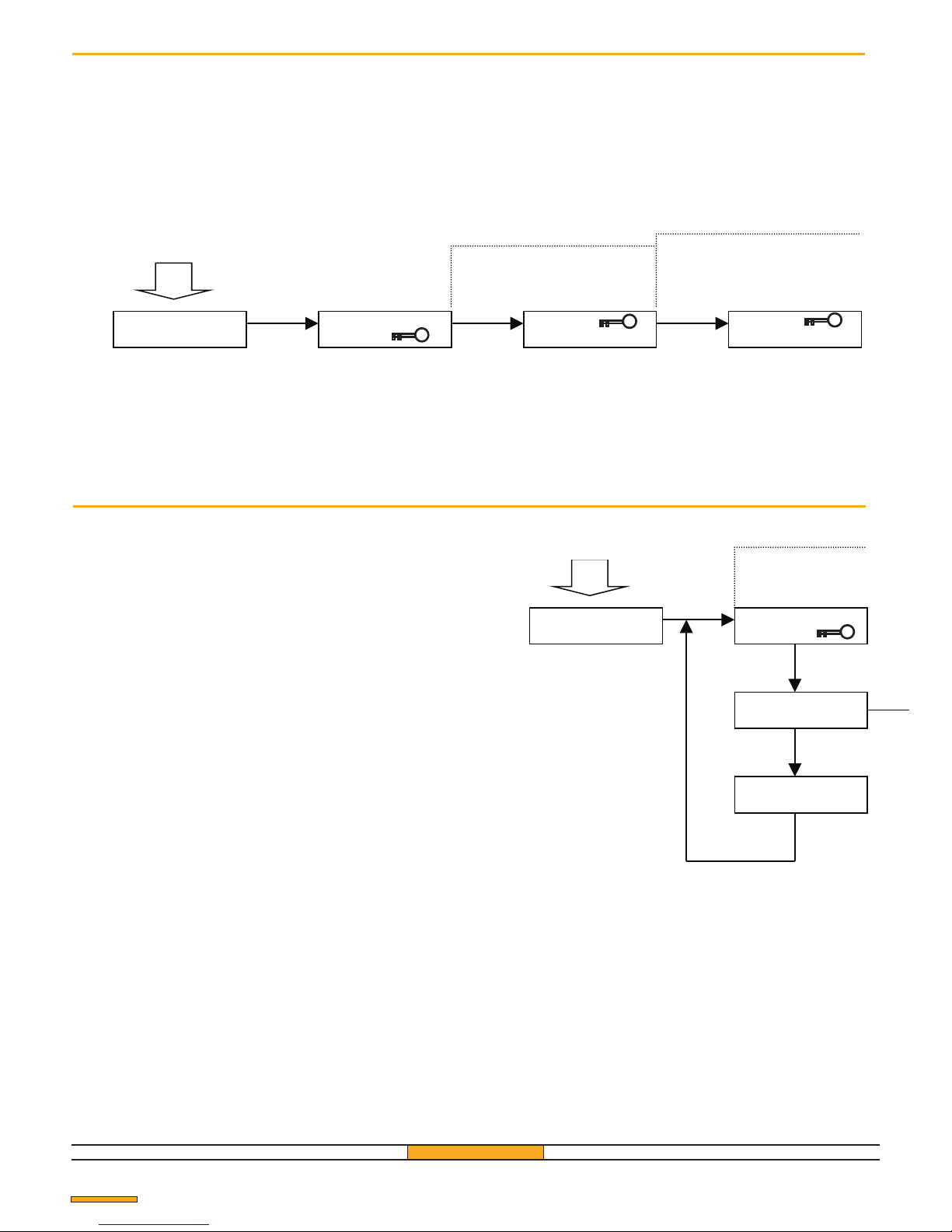
Modifiying the acces code
The default access code is "111111". It is highly advisable to personalize it by setting one of the 65535 possible
combinations in order to deny access to the parameters to unauthorized personnel.
WARNING: If access code is lost, it will not be possible to proceed to the variation of the parameters.
Transmitter
Master Nº 1
Transmitter
Master Nº 1 Master Nº 1
*
*
CURRENT PASSWORD DIALING
MENU
CONFIG. RECEIVER?
CONFIG. RECEIVER
CHANGE ?
CURRENT
INSERT 0 0 0 0 0
NEW
See.
“ENTRY INTO THE MAIN MENU”
SETTING THE
Pag. 10
Choice of the type of relay contact
On each relay 4 types of contact are available:
! Impulsive :pressing a button on the transmitter
activates the relay impulsively.
! Bistable :Pressing the button on the transmitter for
the first time closes the relay contact; pressing it
again the contact is opened.
! Timed 6 sec :Pressing the button on the transmitter
closes the contact for 6 seconds
! Impulsive pedal :Pressing the button on the
transmitter closes relay contact impulsively. The
range of the transmitter is reduced (advisable for
pedal access).
Modifying the type of contact of relay 2 is done by
following the same procedure.
Transmitter
INSERT 0 0 0 0 0
Transmitter
Master Nº 1
MENU CHOICE
MENU
CONFIG. RECEIVER ?
CONFIG. RECEIVER
CHANGE ?
CONFIG. RECEIVER
RELAY: 1?
CONFIG. RECEIVER
RELAY: 2?
Transmitter
Master Nº 1
Transmitter
Master Nº 1
Transmitter
Master Nº 1
YES
YES
YES
YES
NO
NO
NO
See.
“ENTRY INTO THE MAIN MENU”
Page 11
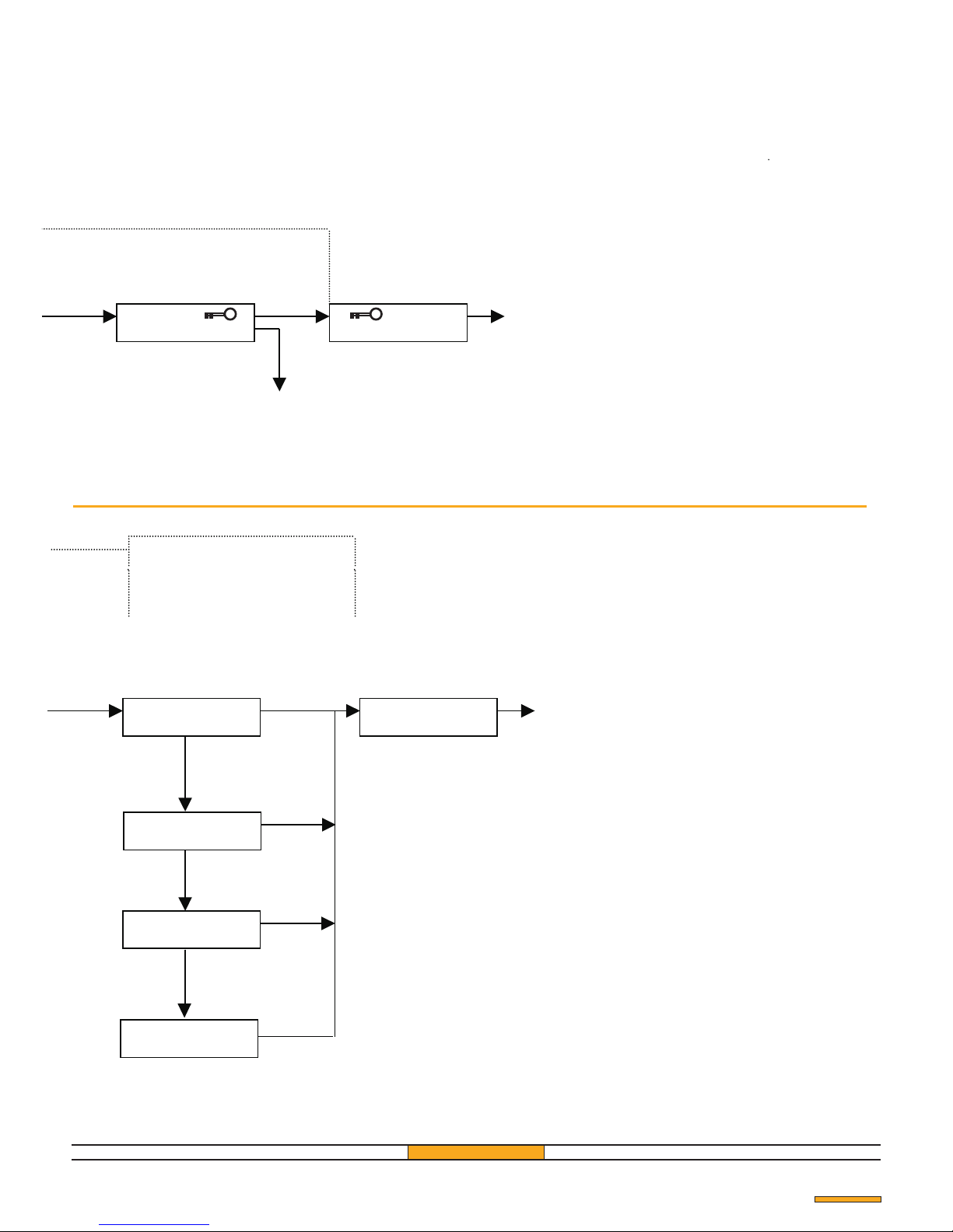
CONTACT TYPE SELECTION
Pag. 11
Transmitter
Master Nº 1 Master Nº 1
Master Nº 1
*
NEW
CONFIRM 0 0 0 0 0
ENABLED
EXECUTED OK
back to the welcome message
NEW PASSWORD
Transmitter
Transmitter
NO
YES
YES
Transmitter
Master Nº 1
Master Nº 1
Master Nº 1
Master Nº 1
Master Nº 1
Master Nº 1
Master Nº 1
Master Nº 1
RELAY : 1
EXECUTED OK
RELAY : 1
PULSE ?
RELAY : 1
STEP ?
Back to welcome
Message
RELAY : 1
TIMED 6 SECONDS ?
RELAY : 1
SHORT RANGE ?
Transmitter
Transmitter
Transmitter
Transmitter
Transmitter
Transmitter
Transmitter
YES
YES
YES
YES
YES
NO
NO
NO
back to the welcome message
Page 12
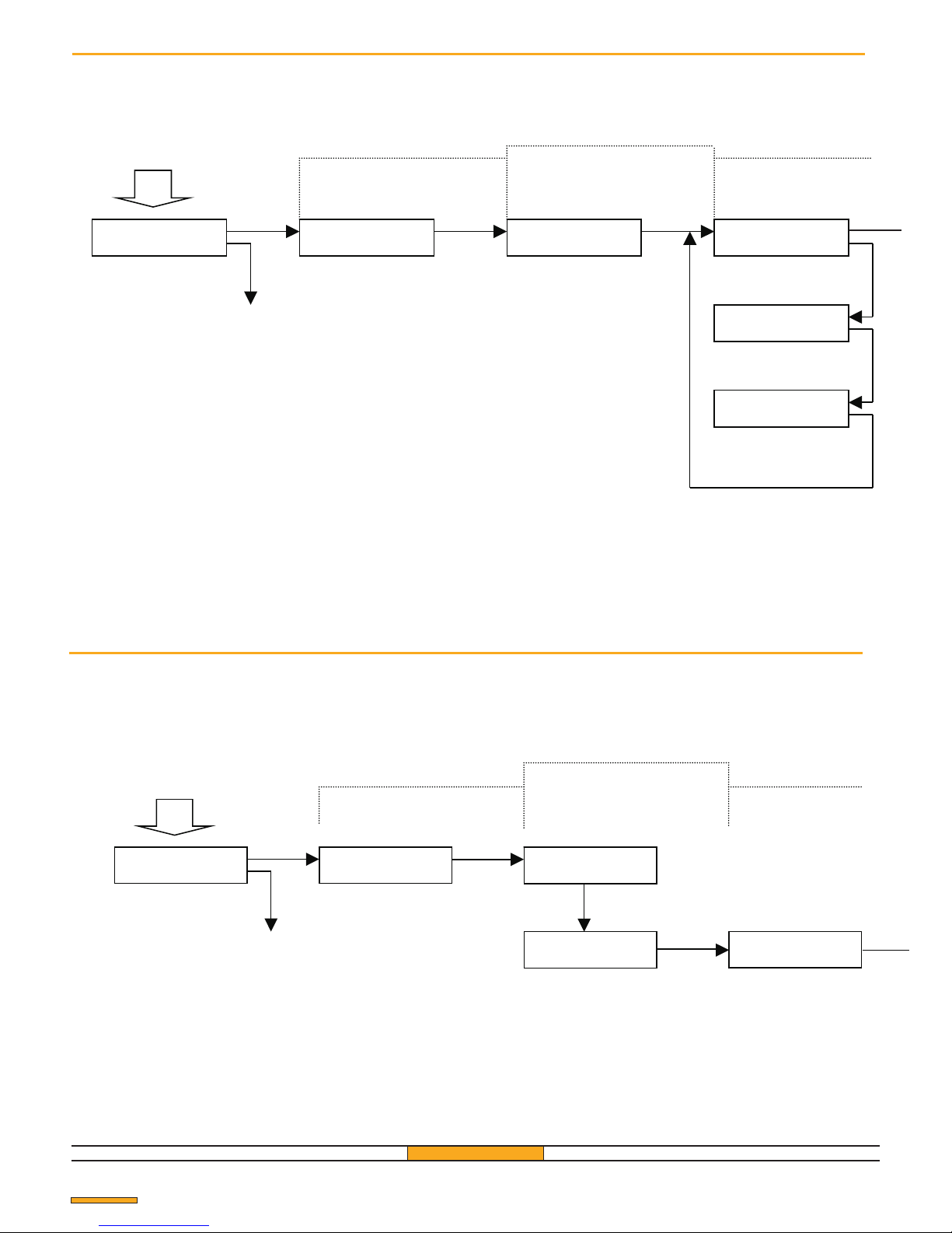
Modify the "Relay" or "Key" parameters
Transmitter
Master Nº 1
Transmitter
Master Nº 1
Transmitter
Master Nº 1
*
TRANSMITTER SELECTION
Transmitter
Master Nº 1
Next menu
Transmitter
Master Nº 1
Transmitter
Master Nº 1
Transmitter
Master Nº 1
RELAY CHANGE
MENU
MODIFY USER
MODIFY USER
USER Nº 001
USER Nº 052
RELAY OR KEY ?
USER Nº 052
RELAY : ½ KEY: A
CHOICE MENU
USER Nº 052
RELAY: 1 KEY: A
USER Nº 052
RELAY: 2 KEY: A
Pag. 12
Determine the memory position of the transmittet to modify (see "Change a number or a letter", p. 5)
Modify the memory position of a transmitter
A transmitter can be moved to a free position.
It is also possible to exchange the position of 2 transmitters.
Determine the memory position of the transmittet to modify (see "Change a number or a letter", p. 5)
YESYESYES
NO
NO
NO
NO
Transmitter
Master Nº 1
Transmitter
Master Nº 1
Transmitter
Master Nº 1
Transmitter
Master Nº 1
*
Transmitter
Master Nº 1
NEW POSITION
Next menu
USER Nº 052
SWAP USERS ?
USER Nº 052
RELAY OR KEY ?
USER Nº 052
SWAP WITH 001
TRANSMITTER SELECTION
CHOICE MENU
MENU
MODIFY USER
MODIFY USER
USER Nº 001
YES
YES
YES
NO
NO
See.
“ENTRY INTO THE MAIN MENU”
See.
“ENTRY INTO THE MAIN MENU”
Page 13
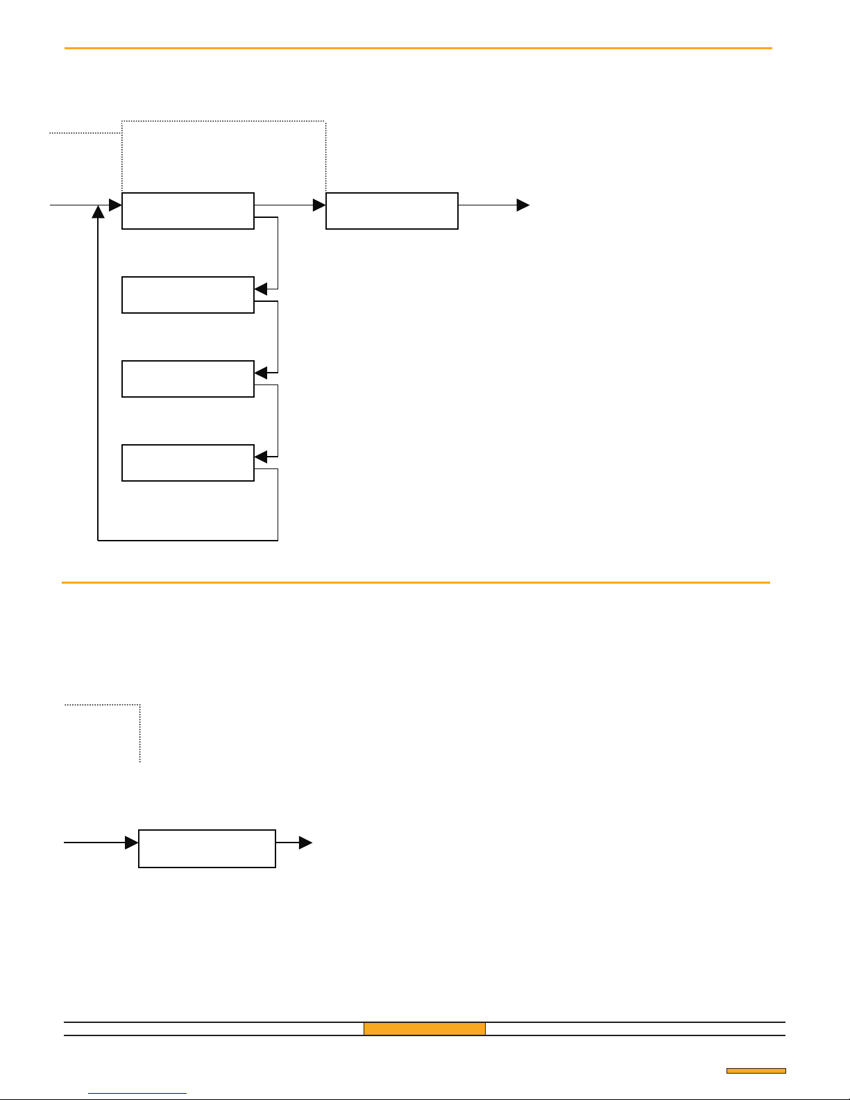
Exit
Transmitter
Master Nº 1
OF MEMORIZATION
USER Nº 052
EXECUTED OK
Pag. 13
Transmitter
Master Nº 1
Transmitter
Master Nº 1
Transmitter
Master Nº 1
Exit
Transmitter
Master Nº 1
Transmitter
Master Nº 1
Transmitter
Master Nº 1
Transmitter
Master Nº 1
USER Nº 052
RELAY: ½ KEY : A
USER Nº 052
EXECUTED OK
USER Nº 052
RELAY: ½ KEY: B
KEY CONFIGURATION
USER Nº 052
RELAY: ½ KEY: C
USER Nº 052
RELAY: ½ KEY: D
YES YES
NO
NO
NO
NO
YES
YES
Page 14
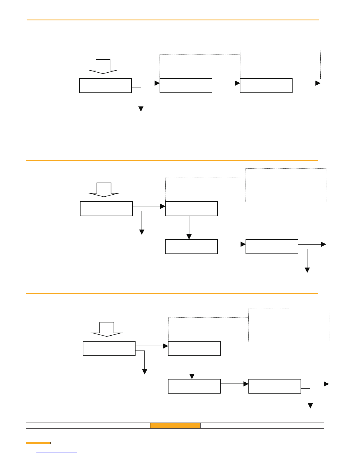
Transmitter
Master Nº 1 Master Nº 1 Master Nº 1
*
CHOICE MENU
TRANSMITTER SELECTION
Master Nº 1
Next menu
Master Nº 1
CHOICE MENU
Master Nº 1
Master Nº 1
Master Nº 1
Master Nº 1
MENU
MODIFY USER?
DELETE
USER ?
DELETE
USER Nº 001
MENU
MEMORY ?
DEL. MEMORY
ARE YOU SURE?
See
“ENTRY INTO THE MAIN MENU”
Transmitter
Transmitter
Transmitter
Master Nº 1
CHOICE MENU
Master Nº 1
Master Nº 1
Master Nº 1
up to the
chosen menu
Master Nº 1
CANCELLATION
Next menu
Master Nº 1
Back to menu delete
MENU
DELETE ?
DELETE
USER ?
DELETE
FROM 1 TO 500?
DEL FROM 1 to 500
ARE YOU SURE ?
Transmitter
Transmitter
Transmitter
Transmitter
Transmitter
Transmitter
CANCELLATION
Master Nº 1
Transmitter
Transmitter
Transmitter
Transmitter
Transmitter
Transmitter
DELETE ?
USER?
DELETE
Next menu
DELETE
Cancelling a user transmitter
Cancelling all the user trasmitters
Complete reinitializing of the receiver
All the transmitters (user and master) are cancelled
and the access code returns to "11111".
Pag. 14
up to the
chosen menu
YES
YES
YES
NO
NO
NO
YES
YES
YES
NO
NO
NO
NO
YES
YES
YES
See.
“ENTRY INTO THE MAIN MENU”
See.
“ENTRY INTO THE MAIN MENU”
Back to menu delete
Page 15
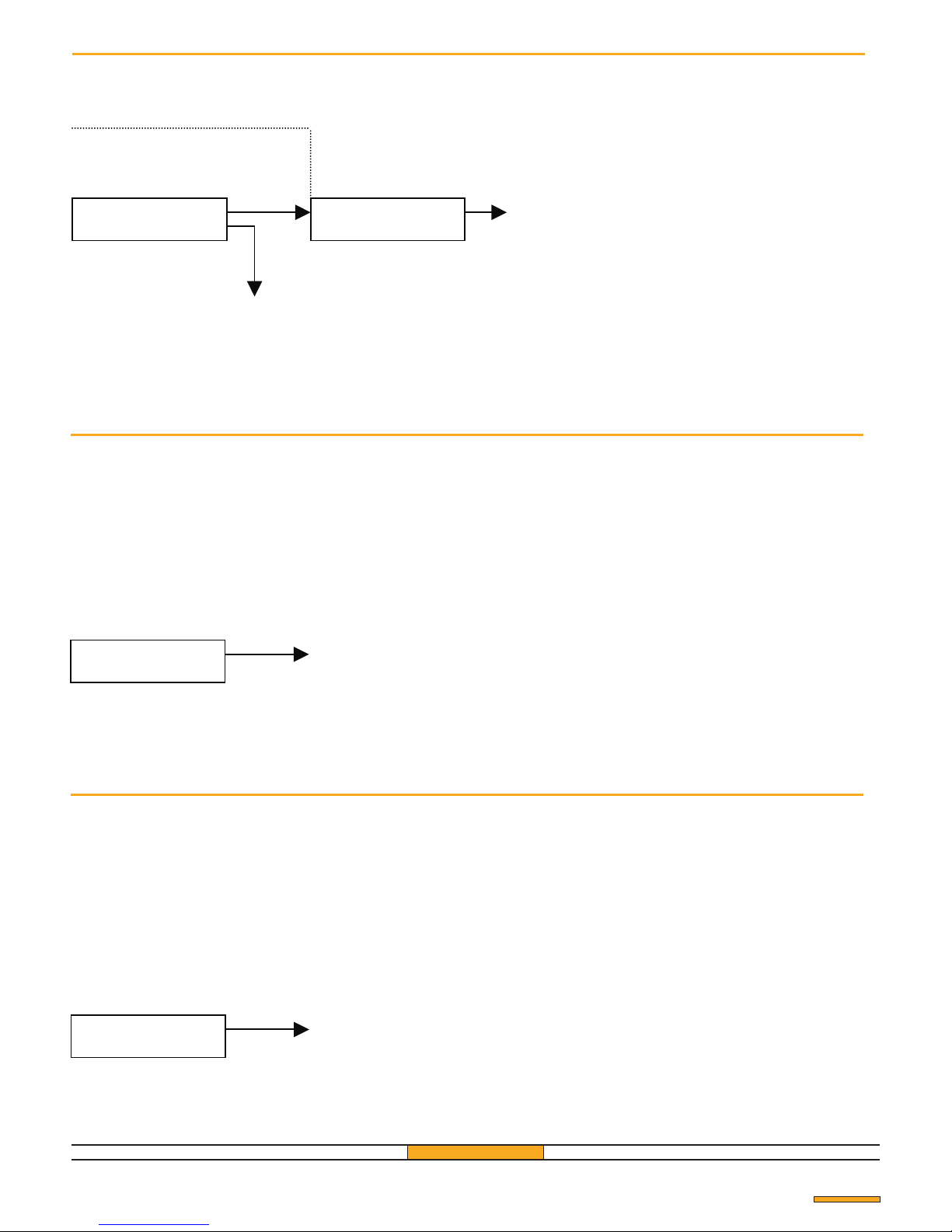
Transmitter
Master Nº 1
CANCELLATION
Master Nº 1
DEL USER 001
ARE YOU SURE ?
DEL USER 001
EXECUTED OK
DEL FROM 1 TO 500
EXECUTED OK
Transmitter
DEL MEMORY
EXECUTED OK
Back to the welcome
Message
Pag. 15
YES
NO
Back to the welcome
Message
Back to menu delete
Back to menu delete
Page 16
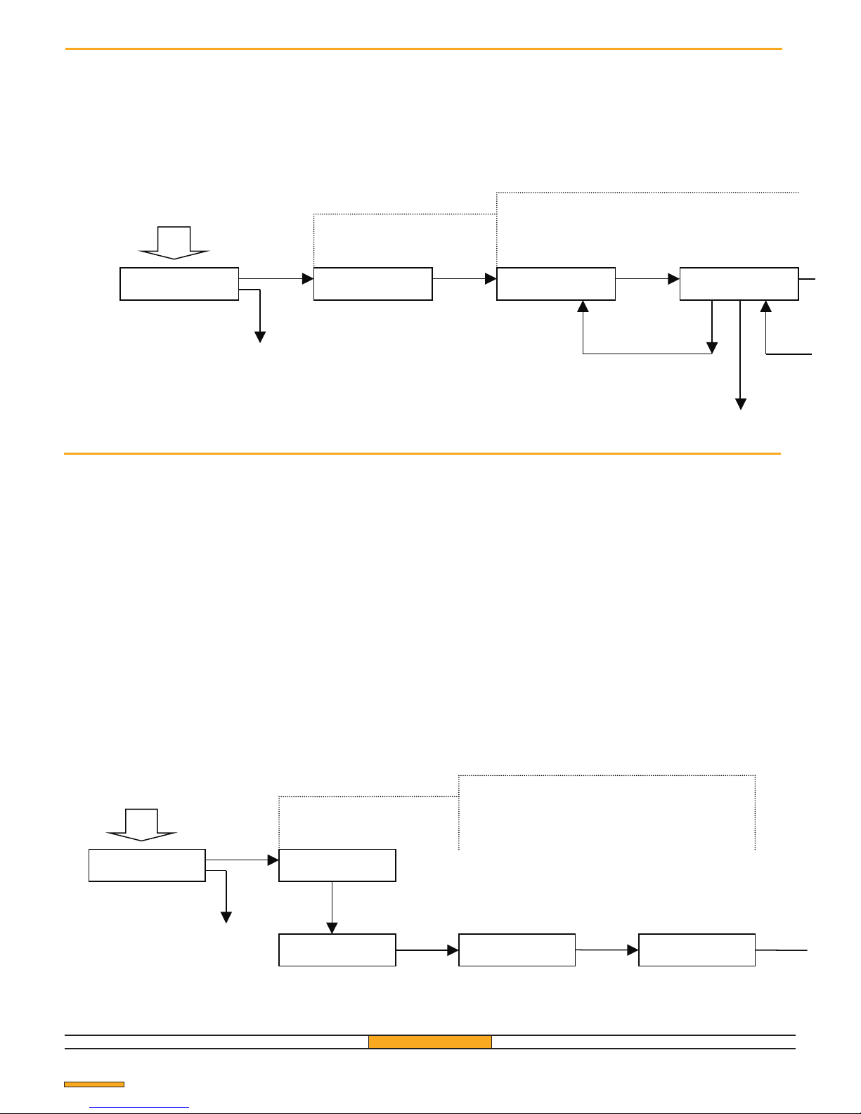
Visualization of the memory on LCD
We can visualize the contents of the memory on the display and read the following parameters for every transmitter:
! memory position;
! relay/s used;
! key used by the transmitter.
Master Nº 1
CHOICE MENU
Automatic
Master Nº 1
TRANSFER
Master Nº 1
Master Nº 1
MENÚ
COPY ?
COPY ON
DISPLAY ?
COPY TO
PRINTER
TRANSFER
IN PROGRESS...
TRANSFER
EXECUTED OK
Print events
We can print a list of the transmitters memorized and for each
of them the following parameters:
- Memory position;
- relay used;
- key used by the transmitter.
It is possible to use this list to carry out installation.
Connection
Connect the receiver and the printer with the appropriate
cable (supplied in the operating kit) using the serial port of
the printer (see fig. 11).
Printer setting
It is only possible to print from a printer with a serial
port.
Baud-rate: 2400 Baud
Number of bit: 8
Parity: None
Stop bits: 1
Handshaking: X ON / X OFF
GfA ELEKTROMATEN UK Ltd advice
During the transfer phase, connect the cables before switching
on the power supply.
Pag. 16
Next menu
Transmitter
Transmitter
Transmitter
up to the
chosen menu
Transmitter
Master Nº 1
CHOICE MENU
Master Nº 1
Transmitter
Master Nº 1
Next menu
MEMORY READING
Transmitter
Master Nº 1
Master Nº 1
Back to the
previous screen
MENU
COPY ?
COPY TO
DISPLAY ?
FIRST USER
US: 001 RL: 1 KY: A
US: 002 RL: 1 KY: B
US: 003 RL: 2 : BKY
Transmitter
Transmitter
Transmitter
YES YES
YES
NO
NO
YES
NO
NO
YES
See.
“ENTRY INTO THE MAIN MENU”
See.
“ENTRY INTO THE MAIN MENU”
NO+YES
Back to Copy Menu
Page 17
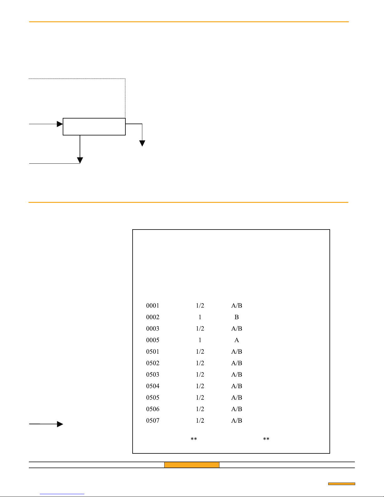
Transmitter
Master Nº 1
Transmitter
Master Nº 1
Transmitter
Master Nº 1
back to the previous
screen
Back to menu
“COPY”
US: 002 RL: 1 KY: B
US: 003 RL: 2 KY: B
Pag. 17
*** GfA 433/500 *** PASSWORD: 54321
INSTALLATION ADDRESS
To be completed by hand
USER Nº
RELAY
KEYS
USER NAME
Example of print-out
To be completed
by hand
End of list
NO+YES
NO
YES
Back to the welcome
Message
Page 18
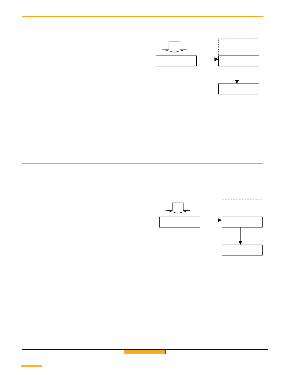
In order to be able to control the transmitters without
moving your own base, it is necessary to copy the
memory of the receiver into another receiver or a backup
memory card.
!Transfer to another receiver
Connect the 2 receivers with the appropriate cable
(supplied in the operating kit - fig. 12). The main receiver
must be connected to a power supply and it will provide
voltage for the second one too
!Transfer to a backup memory
Insert the backup memory into the receiver (see fig. 13)
the right way round.
GfA ELEKTROMATEN UK Ltd Advice
When transferring, connect the cable before switching on the
power.
Pag. 18
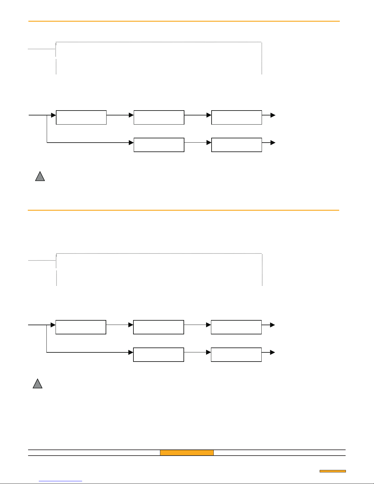
Copy the memory of a receiver into another receiver or into a backup memory
Restore the data from another receiver or a backup memory
!Transfer from another receiver
Connect the 2 receivers with the appropriate cable
(supplied with the operating kit - fig. 12). The main
receiver must be connected to a power supply and it will
provide voltage for the second one too.
!Transfer from a backup memory
Insert the backup memory card into the receiver
(see fig. 13) the right way round
GfA ELEKTROMATEN UK Ltd Advice
When transferring, connect the cable before switching on the
power
Transmitter
Master Nº 1
CHOICE MENU
Master Nº 1
up to the
chosen menu
MENU
COPY ?
COPY ON
DISPLAY?
COPY ON
RECEIVER ?
Transmitter
NO
YES
See.
“ENTRY INTO THE MAIN MENU”
Transmitter
Master Nº 1
CHOICE MENU
Master Nº 1
up to the
chosen menu
MENU
COPY ?
COPY ON
DISPLAY?
COPY FROM
RECEIVER ?
Transmitter
NO
YES
See.
“ENTRY INTO THE MAIN MENU”
Page 19
Pag. 19
Any data contained on the receiver or the backup memory
will be totally erased after transfer.
!
Master Nº 1
TRANSFER
Transmitter
Master Nº 1
Automatic
Automatic
MEMORY BUSY
DELETE ?
TRANSFER
IN PROGRESS..
TRANSFER
EXECUTED OK
Transmitter
Master Nº 1
Transmitter
Master Nº 1
Automatic
Automatic
TRANSFER
Transmitter
Any data contained on the receiver or the backup memory
will be totally erased after transfer.
!
YES
YES
YES
YES
Back to the welcome
Message
Back to the welcome
Message
Back to the welcome
Message
Back to the welcome
Message
TRANSFER
IN PROGRESS..
TRANSFER
EXECUTED OK
TRANSFER
EXECUTED OK
TRANSFER
EXECUTED OK
TRANSFER
IN PROGRESS..
TRANSFER
IN PROGRESS..
MEMORY BUSY
DELETE ?
Page 20
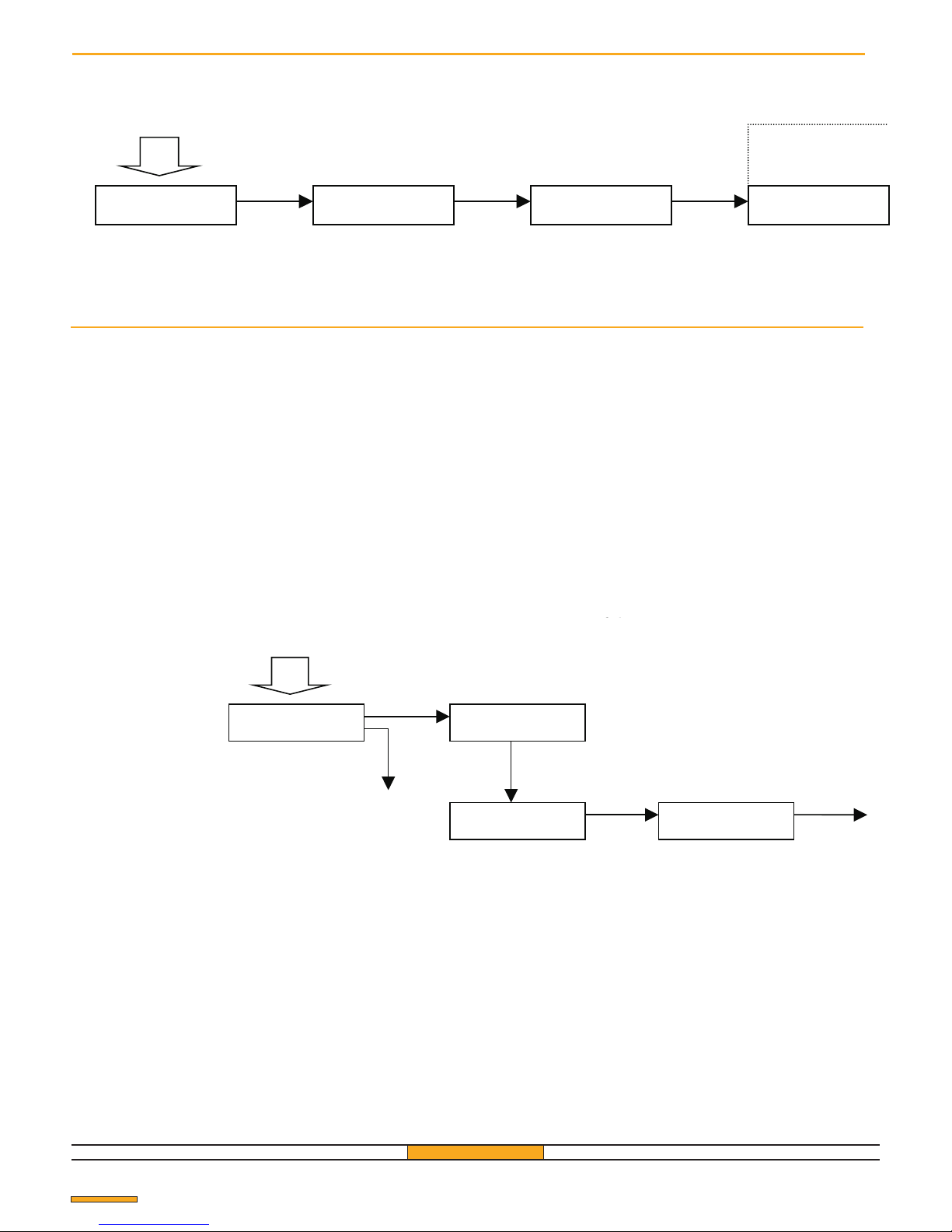
1a) With the backup memory of the site a
transmitter and a “service” receiver.
1 - Connect the backup memory of the site to the service
receiver, being careful to insert it the right way round (see
fig. 13)
2 - Tranfer the contents of the backup memory onto the
receiver (see "Load the memory from another receiver or
from a backup file").
3 - Remove the backup memory
4 - Memorize the transmitter or the transmitters to be
added (see "Memorize one or more supplementary
transmitters" p. 20)
5 - Transfer the data of the service receiver to the TX
Pag. 20
Choose the memory postion of the transmitter (see "Change a number or a letter" p. 5).
Memorize one or more transmitters on site
using the Rx-Tx cable ( see fig. 14 ).
Once completed the transfer , the transmitter is ready to
be memorized on site.
6 - Insert the site backup memory.
7 - Copy the receiver memory onto the backup memory
in order to keep it aligned with the new configuration,
comprehensive also of the new transmitters just
memorized (see "Copy the memory of a receiver or a
backup file").
8 - Remove the backup memory.
WARNING: After transfer, only the first 16
activations of the transmitter key will allow the
memorization of the receiver installed on site.
Memorize one or more transmitters without moving on site
Insert the memory correct way round (see fig. 14). Keep
enough pressure until the message "(EXECUTED)" appears, to
avoid establishing wrong connections between the transmitter
and the cable of the socket, which could cause a deterioration
of the transmitter.
Do not touch the battery with the pins of the socket.
Advice
After having extracted the memory it is possible to test the
transmitter on the receiver used for programming as follows
below:
- delete the transmitter by following the "Delete of a user
transmitter" menu;
- press the 2 buttons (A and B of fig. 15) of the transmitter
simultaneously, release them and the press B again. Once this has
been released the transmitter is memorized.
It is also possible to verify the successful transfer (remember that a
maximum of only 16 impulses are allowed).
GfA ELEKTROMATEN UK Ltd
Transmitter
Master Nº 1
Master Nº 1 Master Nº 1
* *
MENU
STORE USER ?
STORE USER
USER Nº 001
USER: Nº 001
RELAY: ½ KEY: A
USER Nº 001
START ......
Transmitter Transmitter
Master Nº 1
Master Nº 1
Next menu
Transmitter
Master Nº 1
Master Nº 1
up to the
chosen menu
Master Nº 1
MENU
COPY ?
COPY TO
DISPLAY?
COPY TO
TRANSMITTER ?
PROG TRANSMITTER
CONNECTED ?
Transmitter
Transmitter
Transmitter
Transmitter
YES
YES
YES
YES
NO
NO
YES
YES
See.
“ENTRY INTO THE MAIN MENU”
See.
“ENTRY INTO THE MAIN MENU”
Page 21
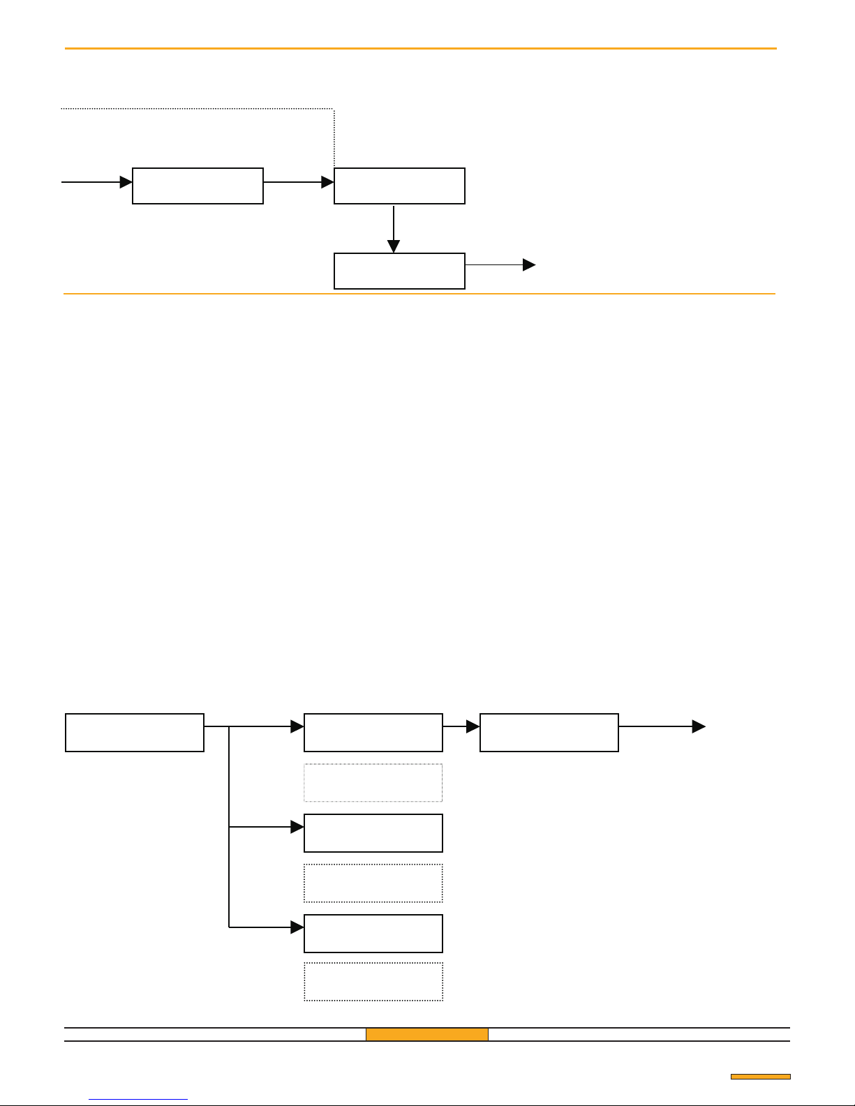
1b) With a “service” receiver but without backup
memory
If the backup memory is not available, you need to know
the password of the receiver installed on site and its free
areas of memory.
- Replace the current password of the service receiver with
the password site receiver.
- Memorize the transmitter or transmitters to be added into
the free areas of the memory (see "Memorize one or more
supplementary transmitters" p. 20).
- Transfer the data onto the transmitter or transmitters by
following the diagram on fig. 14, using the Rx-Tx cable
Once the transfer has been completed, the transmitter is
ready to be memorized on site, see chapter 2.
Pag. 21
WARNING: After transfer, only the first 16
activations of the transmitter key will allow the
memorization of the receiver installed on site.
2 Memorization of the transmitter on site
The transmitter has been configured with the selfmemorization feature : you need just to store it into the
site receiver.
This easy procedure can be done even by the final
customer.
- on site push simultaneously the two keys A and B of the
transmitter (fig. 15), release them and then press key B.
After releasing it the transmitter will have been
memorized.
Transmitter
Master Nº 1 Master Nº 1
Master Nº 1
Master Nº 1
TRANSMITTER MEMORIZATION
US: 001 RL: ½ KY: A
STORE USER ?
EXECUTED OK
ANOTHER .....
EXECUTED OK
USER Nº 001
Transmitter
Transmitter
Transmitter
YES
YES
NO
NO+YES
Transmitter
Master Nº 1
Automatic
Exit
Automatic
Automatic
PROG TRANSMITTER
CONNECTED ?
US: 001 RL: 2 KY: D
EXECUTED OK
PROG. TRANSMITTER
VERIFY...
Transfer OK
US: 001 RL: 2 KY: D
PROG. ERROR
Transfer problem
PROG. TRANSMITTER
DISABLED
NO+YES
This transmitter isn’t
memorized on the receiver
Back to the welcome
Message
Page 22
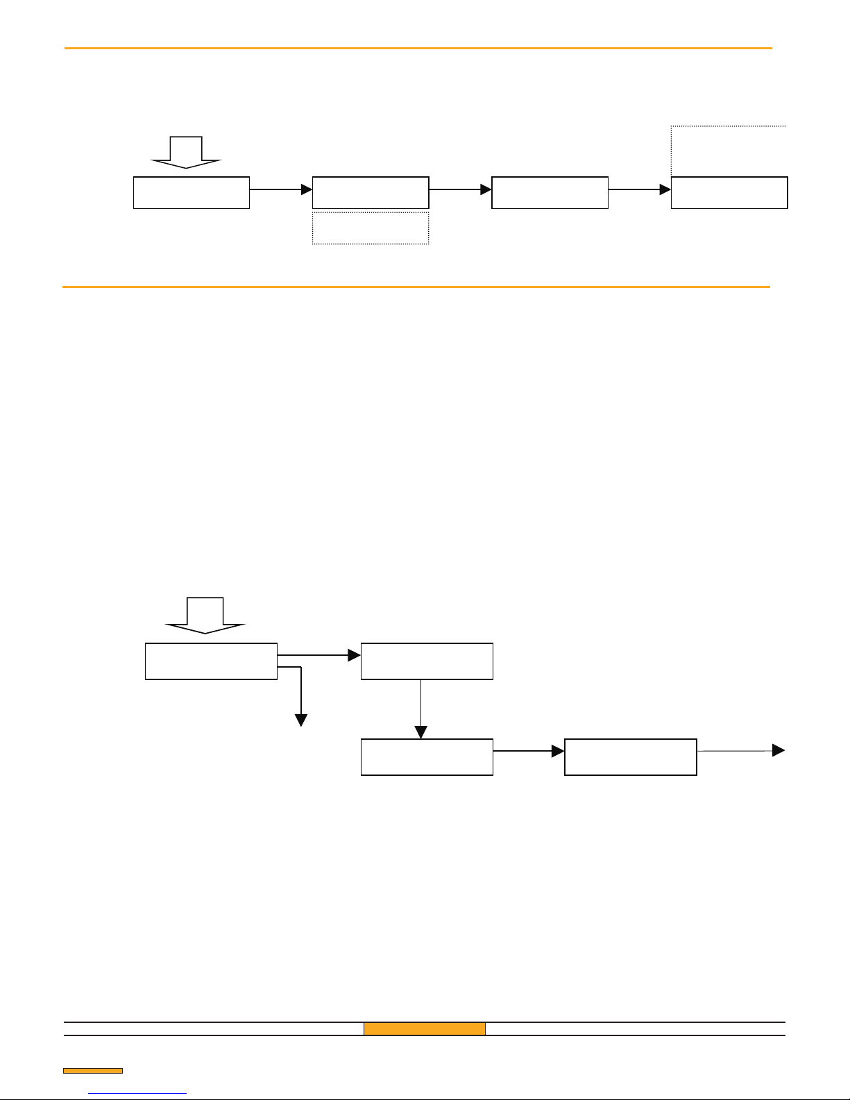
Replace one or more user transmitter on site
It is possible to memorize a transmitter in a memory position which is already occupied. In this case the transmitter
which occupied this position will be cancelled from the memory of the receiver.
Replace one or more transmitters without going on site
Pag. 22
1a) With the backup memory of the site a transmitter
and a “service” receiver.
1 - Connect the backup memory of the site to the service
receiver, being careful to insert it the right way round (see
fig. 13)
2 - Tranfer the contents of the backup memory onto the
receiver (see "Load the memory from another receiver or
from a backup file").
3 - Remove the backup memory
4 - Memorize the transmitter or the transmitters to be
added (see "Memorize one or more supplementary
transmitters" p. 20)
5 - Transfer the data of the service receiver to the TX using
the Rx-Tx cable ( see fig. 14 ).
Once completed the transfer , the transmitter is ready
to be memorized on site.
6 - Insert the site backup memory.
7 - Copy the receiver memory onto the backup
memory in order to keep it aligned with the new
configuration, comprehensive also of the new
transmitters just memorized (see "Copy the memory
of a receiver or a backup file").
8 - Remove the backup memory.
WARNING: After transfer, only the first 16
activations of the transmitter key will allow the
memorization of the receiver installed on site.
Advice
After having extracted the backup memory it is possible to test the
transmitter on the receiver used for programming by following the
instructions below:
- eliminate the transmitter by following the "Elimination of a user
transmitter" menu.
- press the 2 buttons (A and B of fig. 15) of the transmitter
simultaneously, release them and then press B again.
Once this has been released the transmitter is memorized.
GfA ELEKTROMATEN UK Ltd
It is also possible to verify that transfer has taken place
(remember that a maximum of only 16 impulses are allowed).
Transmitter
Master Nº 1
Master Nº 1
Next menu
Master Nº 1
Master Nº 1
up to the
chosen menu
Master Nº 1
MENU
COPY ?
COPY TO
DISPLAY?
COPY TO
TRANSMITTER ?
PROG TRANSMITTER
CONNECTED ?
Transmitter
Transmitter
Transmitter
Transmitter
Transmitter
Master Nº 1 Master Nº 1 Master Nº 1
* *
MENÚ
STORE USER ?
STORE USER
USER Nº 001
USER : Nº 001
RELAY: ½ KEY: A
USER Nº 001
START..?
Select the transmitter
to replace
Transmitter
Transmitter
YES YES
YES
NO
NO
YES
YES YES
See.
“ENTRY INTO THE MAIN MENU”
See.
“ENTRY INTO THE MAIN MENU”
Page 23
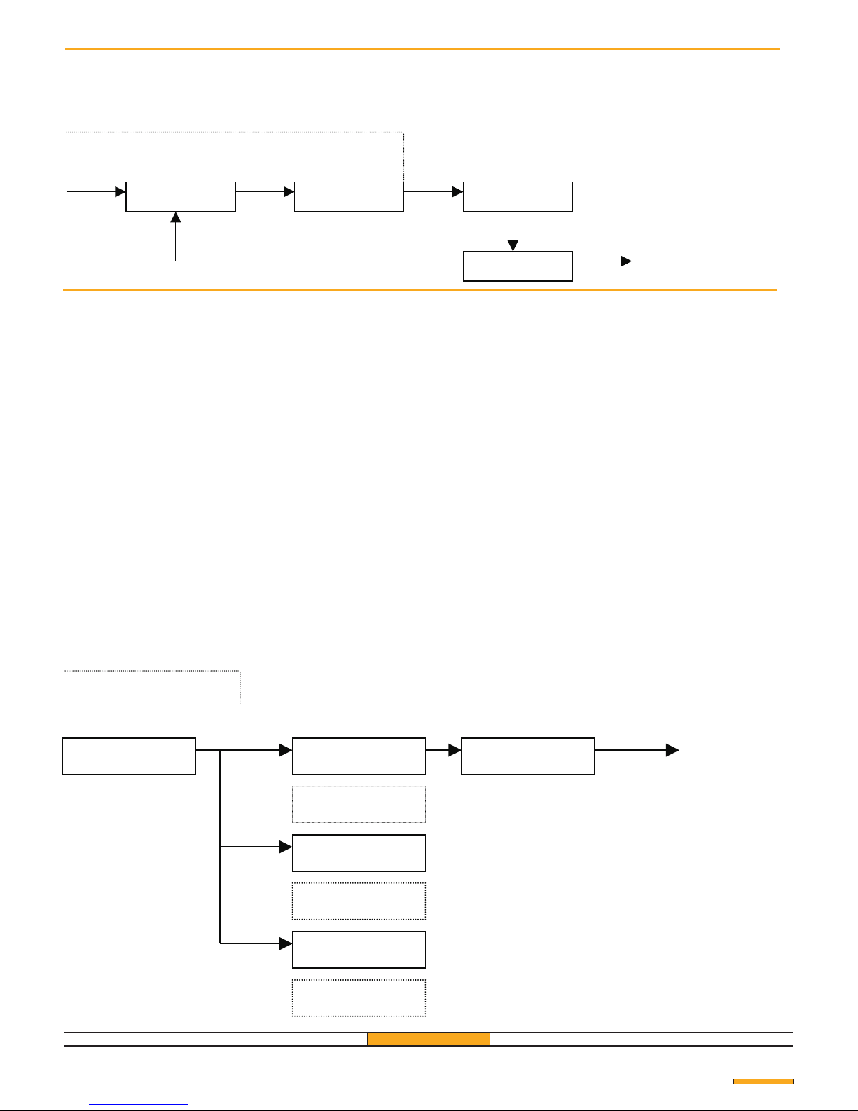
TRANSFER
Transmitter N°1
Replace
Transmitter
Master Nº 1
TRANSMITTER REPLACEMENT
US: 001 RL: ½ KY: A
STORE USER ?
US: 001 RL: ½ KY: A
REPLACE ?
EXECUTED OK
USER Nº 001
back to the welcome message
EXECUTED OK
ANOTHER ...
1b) With a service receiver but without backup
memory
If the site backup memory is not available
know the access code of the site receiver and the memory
positions available for the transmitters.
- Replace the service receiver password with the one the
access code with that of the receiver installed on site.
- Proceed to the memorization of the transmitter or
transmitters to be added (see "Memorize one or more
supplementary transmitters" p. 20).
- Transfer the data to the transmitter or tansmitters by
following the diagram below using the Rx-Tx cable (fig.
14).
Once transfer is complete, the transmitter is ready to be
memorized on site.
, it is necessary to
Transmitter
Master
Automatic
Exit
Automatic
Automatic
PROG TRANSMITTER
CONNECTED ?
US: 001 RL: 2 KY: D
EXECUTED OK
PROG TRANSMITTER
VERIFY ....
Transfer OK
US: 001 RL: 2 KY: D
PROG. ERROR
Transfer problem
PROG. TRANSMITTER
DISABLED
This transmitter isn’t
memorized in the receiver
Pag. 23
WARNING: After transfer, only the first 16
activations of the transmitter key will allow the
memorization of the receiver installed on site.
2 Memorization of the transmitter on site.
The transmitter has been preset but it will only be
memorized in the receiver installed on site after the
following operation:
- on site, press simultaneously the two buttons A and B
of the transmitter (fig. 15), release them and then press
button B.
After releasing it the transmitter will be memorized.
NO+YES
YES YES
NO+YES
NO
NO+YES
Substitute
Transmitter N°1
Replace
Transmitter N°1
Replace
Transmitter N°1
Replace
Transmitter N°1
Replace
Transmitter N°1
Page 24
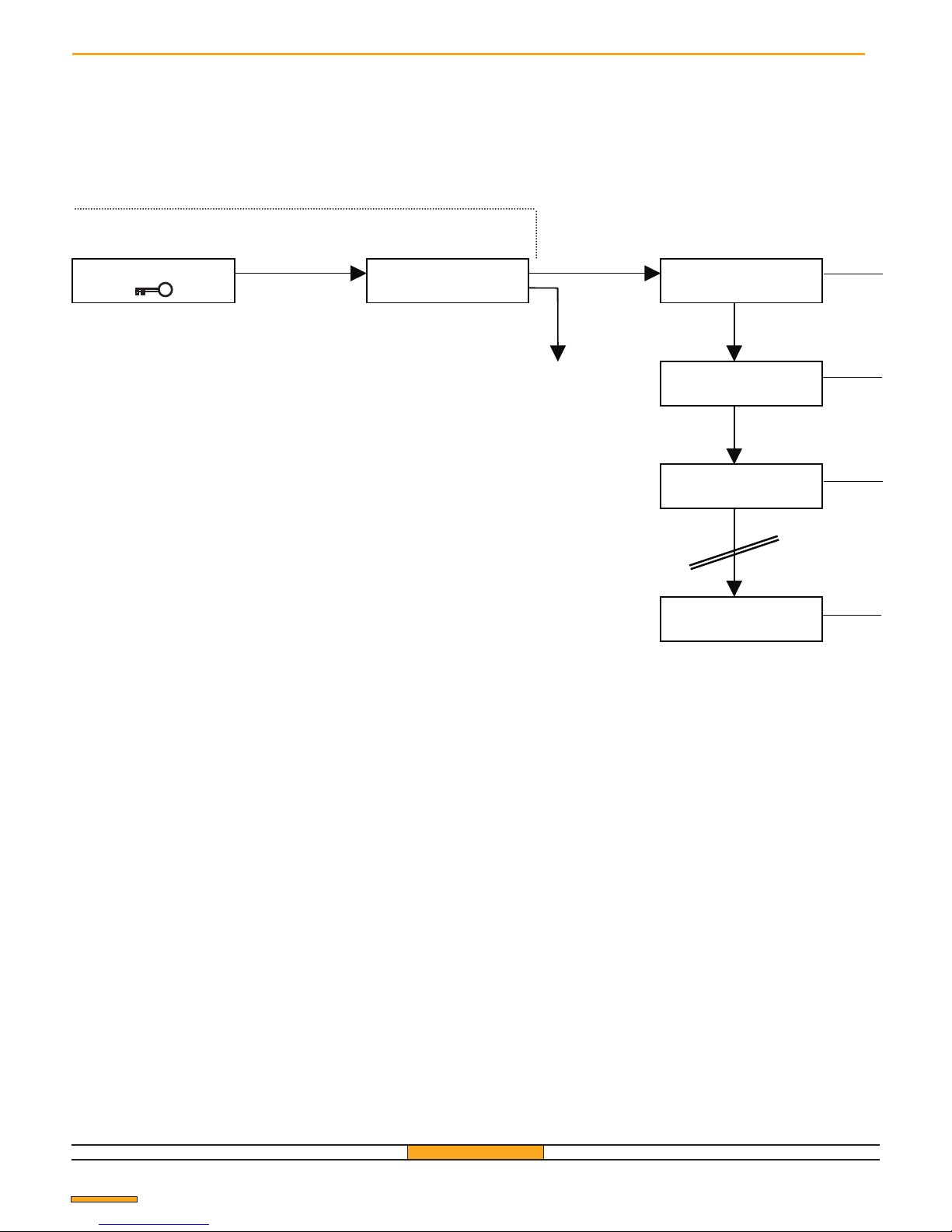
To replace one or more master transmitters it is necessary to set the
default acces code back to "11111" (see "Modify the access code to the
parameters", p. 10).
Transmitter Nº 1
Replace Master
GfA 433/500
US: 501 RL:1/2 KY: A
STORE MASTER?
US: 501 RL:1/2 KY: A
REPLACE ?
US: 502 RL:1/2 KY: A
STORE MASTER?
US: 502 RL:1/2 KY: A
REPLACE ?
US: 502 RL:1/2 KY: A
REPLACE ?
Pag. 24
( Replace one or more master transmitters
REPLACEMENT OF A MASTER TRANSMITTER
NO+YES
YES
NO
NO
NO
NO
Back to the starting
Message
Transmitter Nº 1
Replace Master
Transmitter Nº 1
Replace Master
Transmitter Nº 1
Replace Master
Transmitter Nº 1
Replace Master
Transmitter Nº 1
Replace Master
Page 25
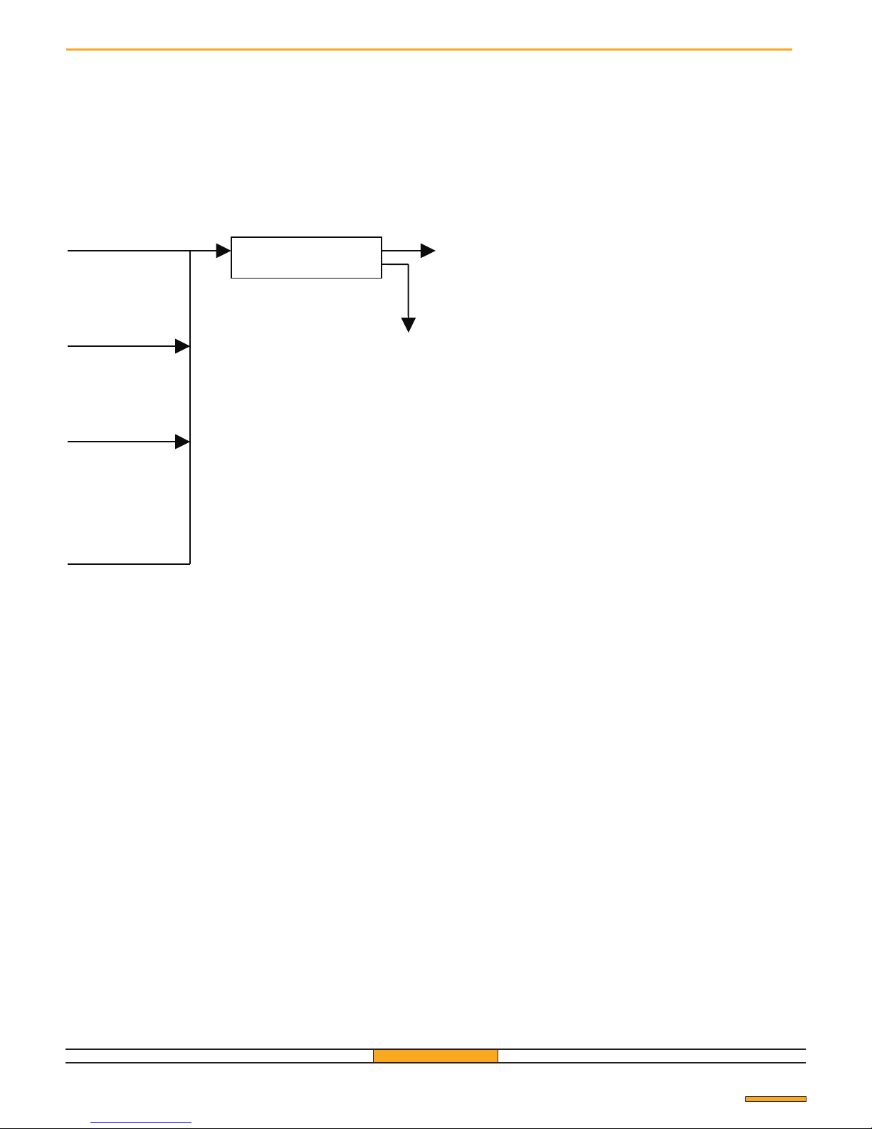
EXECUTED OK
MORE......
Pag. 25
YES
YES
YES
YES
NO
Back to the welcome
Message
Back to the welcome
Message
Transmitter Nº 1
Replace Master
Transmitter Nº 1
Replace Master
Transmitter Nº 1
Replace Master
Transmitter Nº 1
Replace Master
Transmitter Nº 1
Replace Master
Page 26
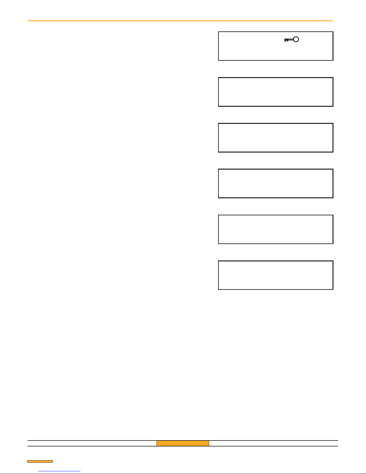
ERROR
US: 002 RL: 1 KY: A
THE CODE EXISTS!
US: 002 RL: 1 KY: A
REPLACE ?
EMPTY MEMORY
USER Nº 001
DISABLED
USER Nº 501
TRANSFER TO
NOT CONNECTED
Particular messages
Introduction of the wrong access code.
Attempt to memorize a transmitter which has already been
memorized.
Attempt to memorize a transmitter in a memory position which is
already occupied.
Attempt to move a transmitter which has not been memorized or
the cancelling of a transmitter which has not been memorized.
Cancelling of a master transmitter.
Failed transfer either due to lack of connection or because the
backup memory has been inserted the wrong way round.
Pag. 26
Page 27
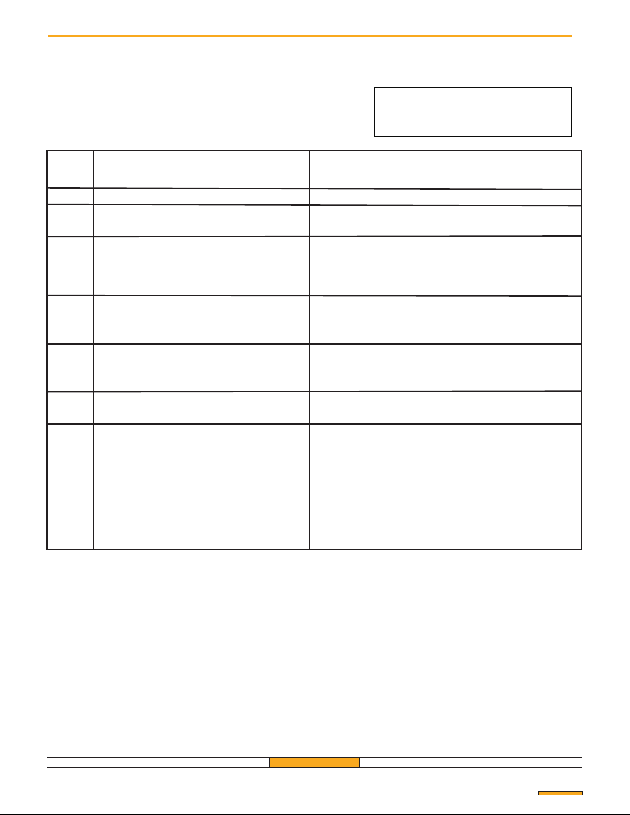
The 433/500 receiver contains an auto-test system which makes it possible to identify
incorrect usages or readings.
Example of the message on the display:
CODE DESCRIPTION ACTION
GfA ELEKTROMATEN UK Ltd
Pag. 27
Receiver auto-test system
SYSTEM
ERROR
Memory empty. Return the receiver to the factory
Copy the contents of the receiver to the backup and
memory and return the receiver to the factory.
Repeat the programming of the transmitter.
If the message is persistent, check the memory position
on the receiver, memorize again, and then start transfer
again.
Memory full
Last memory position: use a previous position or replace
a position already used.
Check the charge on the batteries of the transmitter or
bring the transmitter near the receiver
Transmit a second time
If the message persists, eliminate the memory position of
the transmitter and then memorize again.
If, after the transfer of a transmitter, the number of
impulses allowed (16) has been exceeded, the counter
will no longer be synchronized and the transmitter cannot
be memorized in the receiver.
1 Impossible to write on the memory
2 Reading or writing error on the display
4 Faulty transfer of the data to a transmitter
via connecting cable
8 Used for checking during production
16 Used for checking during production
32 Writing on the last memory position
Es. 500 o 507.
64 Radio signal received too weak
128 Transmitter counter not synchronized
Page 28

Supplied by:
GfA ELEKTROMATEN UK Ltd
Unit 1, Titan Business Centre, Spartan Close
Warwick CV34 6RR, England
Telephone: 01 926 452452 Fax: 01 926 336417
E-mail: [email protected]
Web Site: www.gfa-elektromaten.co.uk
Pag. 28
GUARANTEE
Warranty period : 24 months from the production date placed inside. In this period if the appliance has any
malfuction due to defective component, it will be repaired or replaced by the manufacturer. The warranty
doesn't cover the plastic box The assistance will be perfomed at the manufacturer site
IS-CNDGFA
UK Rev
. 2 del 13.06.2017
Manufactured by:
CDVI Wireless Spa
Via Piave, 23 - 31020
San Pietro di Feletto (TV) - Italy
 Loading...