

Page 1
DE
Die technischen Daten sind unverbindlich. Sie gelten nicht als zugesicherte
Eigenschaften oder als Beschaffenheits- oder Haltbarkeitsgarantien.
Änderungen sind vorbehalten. Es gelten unsere Allgemeinen
Verkaufsbedingungen.
Unter Verwendung der Rückstelleinheit muss die Installationsanleitung des
elektrischen Antriebs Typ EA25-250 beachtet werden.
Bestimmungsgemässe Verwendung
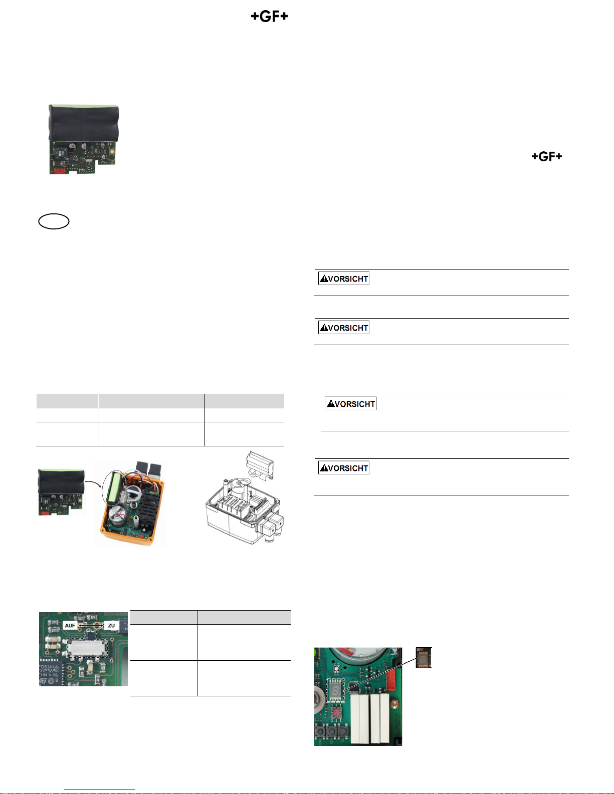
Zusatz-Platine Rückstelleinheit
Die Rückstelleinheit funktioniert mit den Antrieben Typ EA25, EA45, EA120 und
EA250, sowohl für die 24V AC/DC als auch die 100-230V AC Version. Die Platine
wird im Gehäuse des Antriebs in den dafür vorgesehenen Steckplatz
eingesteckt. Die Rückstelleinheit enthält bereits den notwendigen Akku, eine
externe Verdrahtung ist nicht notwendig. (Um bei Bedarf eine externe
Notspannungsversorgung mit 24 V DC anschliessen zu können, ist die Platine
auch ohne Akku erhältlich.)
Bezeichnung
Technische Daten
Code
Rückstelleinheit
Mit integriertem Akku
199 190 601
Rückstelleinheit
extern
Spannungsversorgung
erfolgt extern (24 V DC)
199 190 604
1 Funktion
Bei einem Ausfall der Versorgungsspannung schaltet die Elektronik nach 5 s
automatisch den Akku zu. Mit dem Wahlschalter auf der Platine kann die
Funktion „Anfahren der ZU-Stellung“ oder „Anfahren der AUFStellung“ gewählt werden.
Schalteinstellung
Funktion
Schalter links
Antrieb fährt AUF
(links rum / CCW / Gegen
Uhrzeigersinn)
Schalter rechts
(standard)
Antrieb fährt ZU
(rechts rum / CW / Mit
Uhrzeigersinn)
Die Batterien werden stets geladen gelagert. Sollte die Akkuspannung unter
50% absinken, blinkt der Antrieb gelb und der Ladevorgang wird gestartet.
Sobald U
Akku
grösser 50% beträgt, hört das Blinken auf. Während des
Ladevorgangs kann der Antrieb standardmässig betrieben werden. Beim
Laden zeigt die Fehler LED im Antrieb ein „L“. Das Betriebsbereit Signal bleibt
erhalten.
2 Montage der Rückstelleinheit
Der rechts auf Platine befindliche Taster dient der Ladeüberprüfung. Wenn die
Batterien ausreichend geladen sind, leuchtet nach drücken der Taste die LED
auf der Platine grün. Sollte dies nicht der Fall sein, Platine nicht verwenden.
Platine nicht einstecken wärend die LED auf der Platine grün leuchtet.
Die LED erlischt nach 30s von alleine, danach ist die Platine bereit zur
Installation.
Antrieb von der Versorgungsspannung abtrennen.
1. Gehäusedeckel des elektrischen Antriebs entfernen (dazu die vier
Schrauben lösen und Deckel öffnen).
2. Rückstelleinheit-Platine aus der Verpackung entnehmen und auf
Beschädigungen kontrollieren.
Platine nicht direkt berühren. Elektrostatische Entladungen können
Bauteile beschädigen.
3. Platine senkrecht an der rechten Seite vorne auf die Basisplatine auf den
roten Stecker aufstecken.
Achten Sie darauf, dass die Platine genau in den seitlichen Führungen
liegt und einrastet.
3 Funktion der Rückstelleinheit prüfen
Antrieb mit Spannung versorgen und in AUF-Stellung fahren. Spannung
entfernen. Antrieb fährt nach etwa 5s in die ZU-Stellung (oder umgekehrt, je
nach Einstellung des Schalters).
4. Gehäusedeckel wieder aufsetzen und anschrauben.
4 Störmeldung
Eine Störung kann folgendes auslösen:
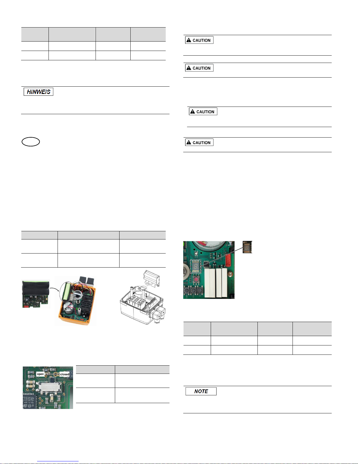
Die 7-Segmentanzeige auf der Basisplatine leuchtet auf, siehe Abbildung
unten.
Die Betriebsbereitmeldung entfällt (Klemme 5,6 NO Kontakt)
LED blinkt gelb auf (ausser bei Stromausfall)
GF Piping Systems
Bedienungsanleitung
Instruction Manual
Elektrische Antriebe Typ EA25-250: Rückstelleinheit
Electric actuators type EA25-250: Fail-safe return unit
Georg Fischer Piping Systems Ltd CH-8201 Schaffhausen
Phone +41 (0)52 631 30 26 / [email protected] / www.gfps.com
700 278 093
GFDO_6428_1a_4a (04.16)
© Georg Fischer Piping Systems Ltd
CH-8201 Schaffhausen/Switzerland, 2016
Page 2
Zuordnung der Fehlercodes bei Störmeldungen
Wenn die Rückstelleinheit installiert ist, können folgende Fehlercodes
angezeigt werden:
Fehlercode
Beschreibung
Signal
Betriebsbereit
EA Reaktion
Akkuspannung < 50%
Ja
Normalbetrieb
Akku defekt
Nein
Normalbetrieb
Für weitere Fehlercodes der Basisplatine, siehe Bedienungsanleitung des elektrischen
Antriebs Typ EA25-250.
Störmeldung beheben
Fehlerursache kontrollieren, ggf. entsprechende Wartung durchführen.
Behebung der Störung ist möglich, während die Versorgungsspannung
noch anliegt oder wenn der Antrieb von der Netzspannung kurz getrennt
wird (nicht wirksam bei Zyklusüberwachung).
Zur Behebung den „SET“-Taster auf der Basisplatine betätigen.
EN
The technical data are not binding and not expressly
warranted characteristics of the goods. They are
subject to change. Our General Conditions of Sale apply.
Using the monitoring, the instruction manual of the electric
actuator type EA 25-250 must be observed.
Intended use
Accessory board Fail-safe return unit
The monitoring can be used with the electric actuators type EA25, EA45, EA120
and EA250, both with the 24V AC/DC as well as the 100-230V AC version. The
board is to be plugged into the housing of the actuator in the provided slots.
The fail-safe return unit already includes the required battery; no external
wiring is necessary. (If required, the board is available without battery for
connecting an emergency external power source with 24 V DC.)
Description
Technical data
Code
Fail-safe return
unit
With integrated battery pack
199 190 601
Fail-safe return
unit external
Voltage supply implemented
externally (24 V DC)
199 190 604
1 Function
In case of a failure of the supply voltage, the battery is electronically switched
on automatically after 5 s. With the selector switch on the board, the functions
"Move to CLOSE position" or "Move to OPEN position" can be selected.
Switch position
Function
Switch left
Actuator moves to OPEN
(counterclockwise)
Switch right
(standard)
Actuator moves to CLOSE
(clockwise)
The batteries are always stored charged. If the battery charge level drops
below 50 %, the actuator LED flashes yellow and the charge cycle starts. Once
U
Batt
rises above 50 %, the flashing stops.
During the charge cycle, the actuator can be operated normally. When
charging the internal Error LED displays “L”. The ready to operate signal stays.
2 Assembly of the fail-safe return unit board
The push button on the right side of the PCB is used to check the charge status
of the batteries. If status is “ok” the LED on the PCB will light up green after
pressing this button. If no green light occurs do not use this PCB.
The board must not be plugged into the actuator while the green LED is
activated on the.PCB.
LED turns off after 30s, then the board is ready to be installed.
Disconnect the actuator from the supply voltage.
1. Remove housing cover of the electric actuator (loosen the 4 screws, open
cover).
2. Take the fail-safe return unit board out of the packaging and check for
damages.
Do not touch the board itself. Electrostatic discharge can damage the
components.
3. Insert board vertical on the backside of the main board onto the red plug.
Ensure that the board sits in the lateral guides and snaps.
3 Test functioning of the fail-safe return unit
Apply power to the actuator and move into position OPEN. Remove power to
the actuator. Actuator moves after about 5s to CLOSE position (or reversed,
depending on the setting of the switch).
4. Put the cover back in place and fasten it with the 4 screws.
4 Error message
An error can triggers the following:
The 7-segment display on the main board illuminates; see illustration
below.
The ready-to-operate signal will be off (terminals 5,6 NO contact)
LED flashes yellow (except in case of power outage)
Assignment of error codes for error messages
If the fail-safe return unit PCB is installed, the following error codes can be
displayed:
Error code
Description
Signal „Readyto-operate“
EA response
Battery voltage < 50%
Yes
Normal operation
Battery faulty
No
Normal operation
For further error codes of the main board, see instruction manual of the electric actuator
type EA 25-250.
Acknowledge error message
Check the cause of fault, if necessary, carry out relevant maintenance.
The message can be eliminated while the supply voltage is still connected
or the actuator is briefly disconnected from the mains voltage (does not
work with cycle monitoring).
Error can be acknowledged via the „SET“ button on the main board.
 Loading...