

Page 1
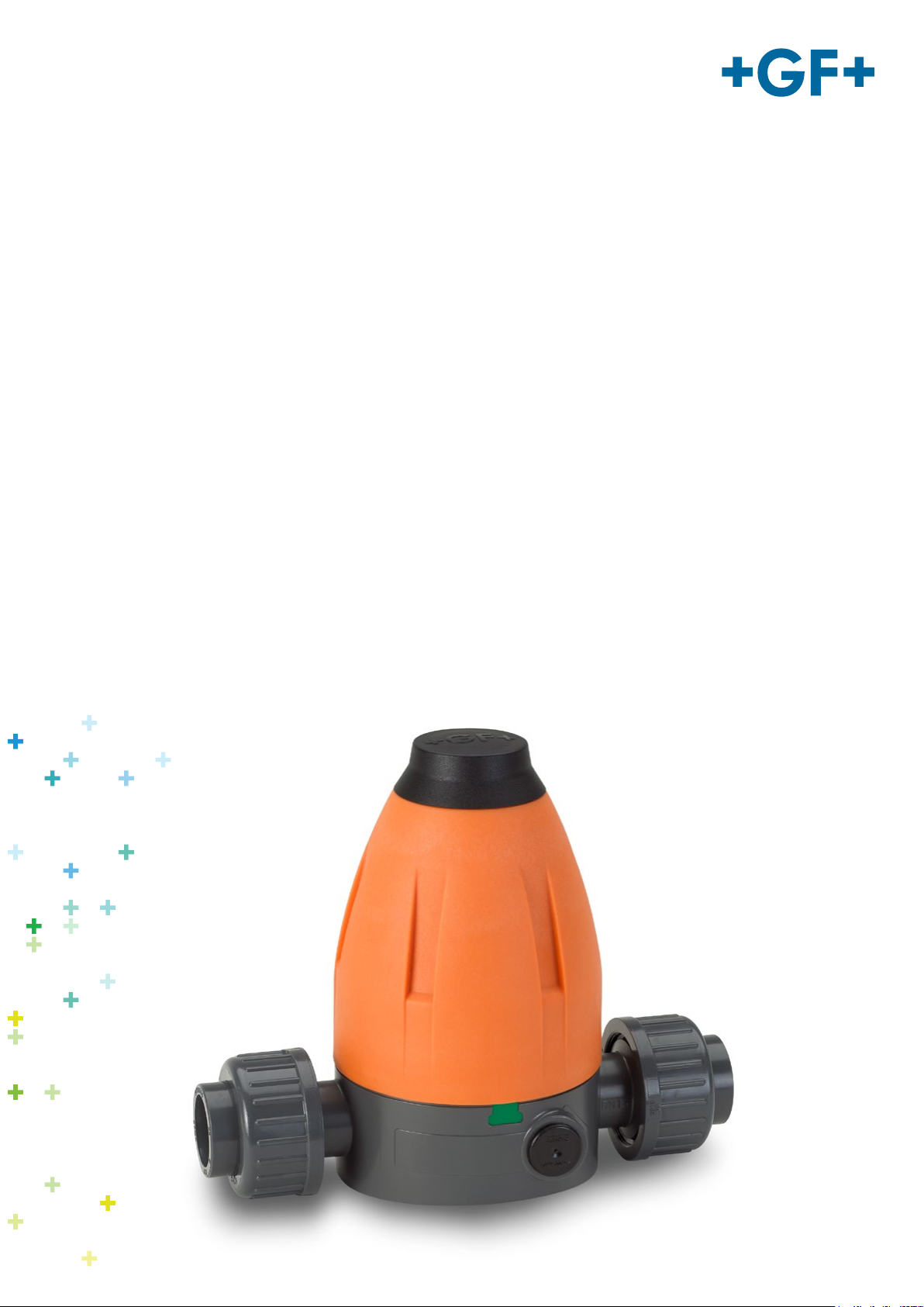
GF Piping Systems
Bedienungsanleitung
Instruction manual
Manuel d‘utilisation
Manual de instrucciones
Druckreduzierventil Typ 582
Pressure Reducing Valve Type 582
Réducteur de pression type 582
Válvula reductora de presión tipo 582
Druckhalteventil Typ 586
Pressure Retaining Valve Type 586
Détendeur de pression type 586
Válvula de retención de presión tipo 586
Page 2

Translation of the original instructions
Disclaimer
The technical data are not binding. They neither constitutes expressly warranted
characteristics nor guaranteed properties nor a guaranteed durability. They are subject to
modification. Our General Terms of Sale apply.
Observe instruction manual
The instruction manual is part of the product and an important element within the safety
concept.
Read and observe instruction manual.
Always have instruction manual available by the product.
Give instruction manual to all subsequent users of the product.
Page 3

Contents Instruction manual
Contents
Contents ..........................................................................................................................................28
1 About this document ...............................................................................................................29
1.1 Warnings ..........................................................................................................................29
1.2 Further symbols and labels ............................................................................................29
1.3 Other related documents ................................................................................................29
2 Safety and responsibility ........................................................................................................30
2.1 Intended use ....................................................................................................................30
2.2 Safety information ...........................................................................................................30
3 Transport and storage ............................................................................................................30
4 Design ......................................................................................................................................31
4.1 Pressure reducing valve .................................................................................................31
4.2 Pressure retaining valve .................................................................................................32
4.3 Manometer ......................................................................................................................33
5 Function ...................................................................................................................................33
5.1 Pressure reducing valve .................................................................................................33
5.2 Pressure holding valve ...................................................................................................33
6 Identification ............................................................................................................................34
6.1 Valve type/sealing material (O-rings).............................................................................34
7 Technical specifications .........................................................................................................34
8 Required tools .........................................................................................................................35
9 Installation ..............................................................................................................................35
10 Operation .............................................................................................................................38
10.1 Pressure test ...................................................................................................................38
10.2 Setting the working pressure .........................................................................................38
11 Maintenance ........................................................................................................................40
11.1 Replacing diaphragm and O-ring ...................................................................................41
11.1.1 Disassembly .............................................................................................................41
11.1.2 Assembly ..................................................................................................................43
11.2 Cleaning the inner body ..................................................................................................45
12 Troubleshooting ..................................................................................................................46
13 Spare Parts..........................................................................................................................48
14 Accessories .........................................................................................................................48
15 Disposal ...............................................................................................................................48
16 EC Manufacturer's declaration ..........................................................................................49
28
Page 4
Instruction manual About this document
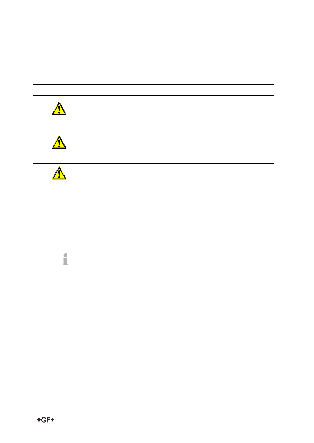
Warning symbol
Meaning
DANGER
Imminent danger!
Non-observance of these warnings can result in death or extremely
severe injuries.
Measures to avoid the danger.
WARNING
Possible imminent danger!
Non-observance of these warnings can result in severe injuries.
Measures to avoid the danger.
CAUTION
Dangerous situation!
Non-observance of these warnings can result in minor injuries.
Measures to avoid the danger.
CAUTION
Dangerous situation!
Non-observance of these warnings can result in material damage.
Measures to avoid the danger.
Symbol
Meaning
Remarks: Contain especially important information for better
understanding.
Call for action: Here, you have to do something.
1.
Call for action in a certain order: Here, you have to do something.
1 About this document
1.1 Warnings
In this instruction manual, warnings are used, which shall warn you of death, injuries or
material damage. Always read and observe these warnings!
1.2 Further symbols and labels
1.3 Other related documents
Georg Fischer planning fundamentals industry
These documents can be obtained via the agency of GF Piping Systems or under
www.gfps.com.
29
Page 5

Safety and responsibility Instruction manual
2 Safety and responsibility
2.1 Intended use
Pressure reducing valves type 582 and the pressure retaining valves type 586 are intended to
be operated with pure, non-abrasive liquid media. The product and all of its components are
intended to be used within the permitted pressure and temperature limits and in accordance
with their chemical resistance.
Pressure reducing valve type 582
The pressure reducing valves type 582 are intended to reduce the system pressure, after
installation into a piping system, and to keep it constant at the specified value to the greatest
possible extent.
Pressure retaining valve type 586
The pressure retaining valves of type 586 are intended to keep the system pressure, after
installation into a piping system, and to keep it constant at the specified value to the greatest
possible extent.
Foreseeable misuse
The pressure reducing valves type 582 and the pressure retaining valves type 586 are not
intended to be used as shut-off devices.
The pressure reducing valves type 582 and the pressure retaining valves type 586 are not
intended to be operated with gases or other compressible media.
2.2 Safety information
In order to provide safety in the plant, the operator is responsible for the following
measures:
Only use product as intended, see intended use.
Do not use any damaged or faulty product. Sort out any damaged product immediately.
Make sure that the piping system has been installed professionally and is inspected
regularly.
Product and accessories shall only be installed by persons who have the required training,
knowledge or experience.
Regularly train personnel on all questions pertaining to the locally applicable regulations
on occupational safety and environmental protection, especially on pressure-retaining
pipelines.
3 Transport and storage
Protect the product against external force during transport (impact, stroke, vibrations
etc.).
Transport and/or store product in its unopened original packaging.
Protect the product from dust, dirt, moisture as well as heat and ultraviolet radiation.
Ensure that the product has not been damaged neither by mechanical nor thermal
influences.
Check the product prior to assembly on transport damages.
30
Page 6
Instruction manual Design
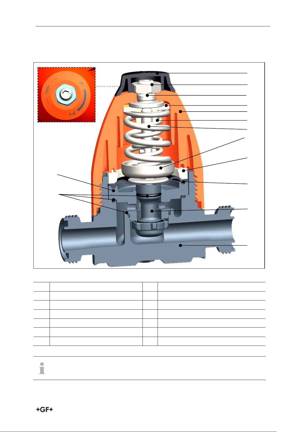
1
Cap
8
Compression piece
2
Locking nut
9
Retaining ring
3
Spindle/adjusting screw
10
Diaphragm
4
Spring retainer
11
Piston
5
Bonnet assembly (top part) *
12
Body
6
Inner spring
13
O-rings
7
Outer spring
14
Inner body
Diaphragm, O-rings, diaphragm washer, inner body and piston constitute the
cartridge.
* graphic
identification for
pressure reduction (-)
or
pressure increase (+)
1 2 3
11 4 6 5 12
10
9 8 13
14
7
4 Design
4.1 Pressure reducing valve
31
Page 7
Design Instruction manual
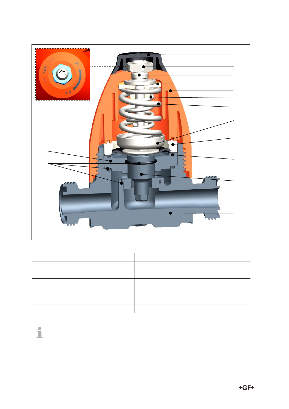
1
Cap
8
Pressure piece
2
Locking nut
9
Retaining ring
3
Spindle/adjusting screw
10
Diaphragm
4
Spring retainer
11
Piston
5
Bonnet assembly (top part)*
12
Body
6
Inner spring
13
O-rings
7
Outer spring
14
Inner body
Diaphragm, O-rings, diaphragm washer, inner body and piston constitute the
cartridge.
* graphic
identification for
pressure reduction (-)
or
pressure increase (+)
1 2 3
11 4 6 5 12
10 9 8
13
14
7
4.2 Pressure retaining valve
32
Page 8
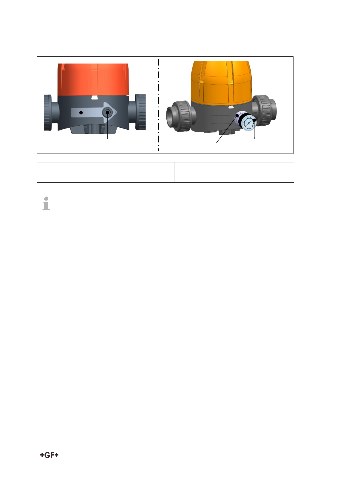
Instruction manual Function
15
Indication of flow direction
17
Manometer adaptor (optional)
16
Manometer socket
18
Manometer
If pressure reducing valve type 582/pressure retaining valve type 586 is a
manometer version, then the manometer is already fitted at the factory.
15
17
18
16
4.3 Manometer
5 Function
5.1 Pressure reducing valve
On the side of the valve outlet, the pressure acts via the diaphragm on the adjustable spring.
A balance of forces is established via the preloaded spring, which is set with the adjusting
screw at the valve. If the outlet pressure increases above the specified value, the piston is
lifted against the spring force. The valve closes, and the outlet pressure is reduced. If the
outlet pressure decreases below the value, the piston is pushed down by the spring
resistance. The valve begins to open, until the balance is reached again. Independent of an
increasing or decreasing inlet pressure, the outlet pressure remains constant to the greatest
possible extent, because it is not directly related to the inlet pressure.
5.2 Pressure holding valve
The desired pressure in the valve inlet pipe is set by the adjustable spring force. If the inlet
pressure rises above the set value, e.g. due to an over capacity of the pump, the valve piston is
lifted against the spring force. Consequently, the valve opens, and there is a reduction of
pressure in the outlet. If the pressure decreases in the valve inlet pipe, the spring resistance
pushes the piston down in the direction of the valve seat and closes, as soon as the inlet
pressure sinks below the preset spring tension. In this way, a constant pressure in the supply
line is ensured.
33
Page 9
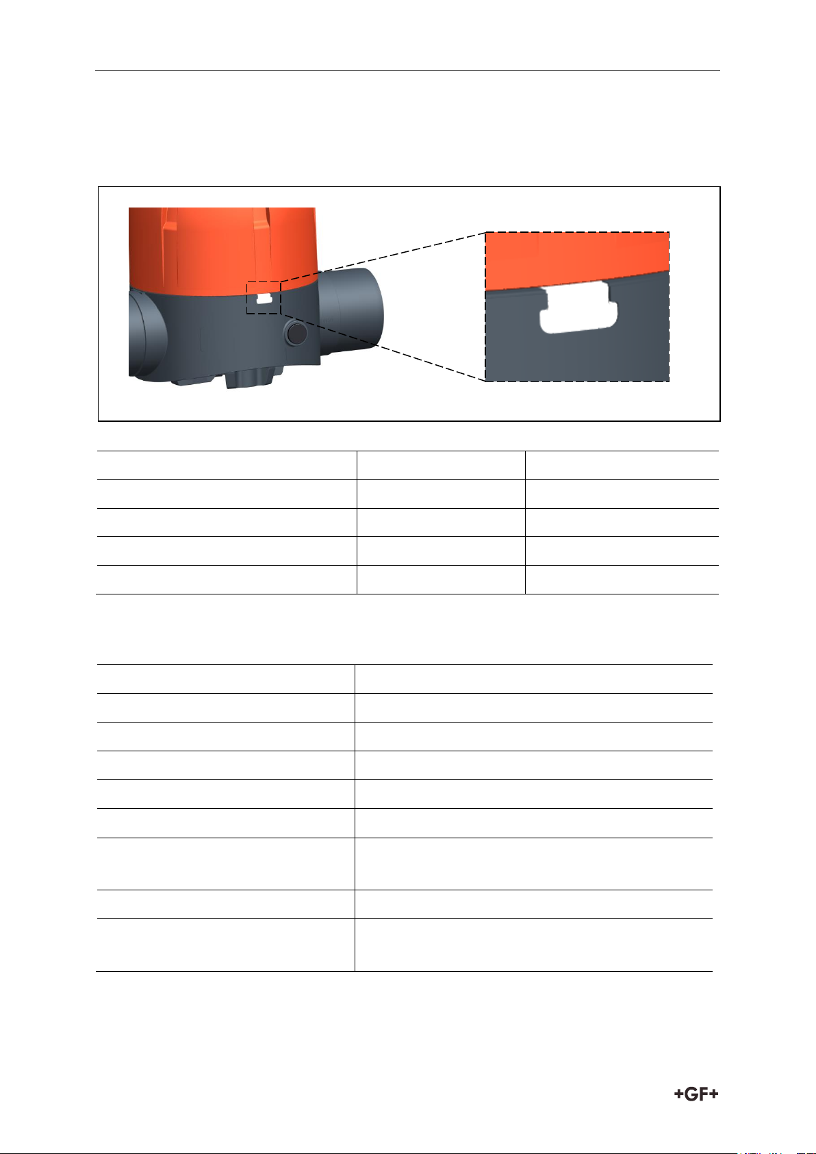
Identification Instruction manual
Valve type
Sealing material
Colour of index plate
Pressure reducing valve type 582
EPDM
white
Pressure reducing valve type 582
FKM
green
Pressure retaining valve type 586
EPDM
black
Pressure retaining valve type 586
FKM
red
Dimensions
DN 10-50 (3/8“ – 2“)
Materials
PVC-U, PVC-C, PP-H, PVDF
Diaphragm
EPDM/PTFE
Gaskets
EPDM, FKM
Connections
Fittings, spigots
Pressure level (nominal pressure)
PN 10
Adjustable pressure ranges
0.5 - 9 bar / optional 0.3 - 3 bar
(7 - 130 psi / optional 4 - 44 psi)
Hysteresis
max. 0.5 bar (max. 6 psi)
Pressure difference
Pressure difference between inlet and outlet:
min. 1 bar
6 Identification
6.1 Valve type/sealing material (O-rings)
s
7 Technical specifications
34
Page 10
Instruction manual Required tools
Tool
DN 10/15
DN 20/25
DN 32/40/50
Allen wrench
AF 6
AF 8
AF 10
Open-end wrench
AF 19
AF 24
AF 30
Hook wrench or strap wrench
80 - 90 mm
95 - 100 mm
135 - 145 mm
Screw driver
Size 1
Fixing unit, e.g. jaw vice
no difference
WARNING – ONLY FOR MANOMETER VERSION
Danger of material damage and/or injury due to changes of the manometer!
Valid for versions with and without adaptor.
The manometer is installed, preset and checked at the factory. Therefore,
ensure that no changes are made at the manometer.
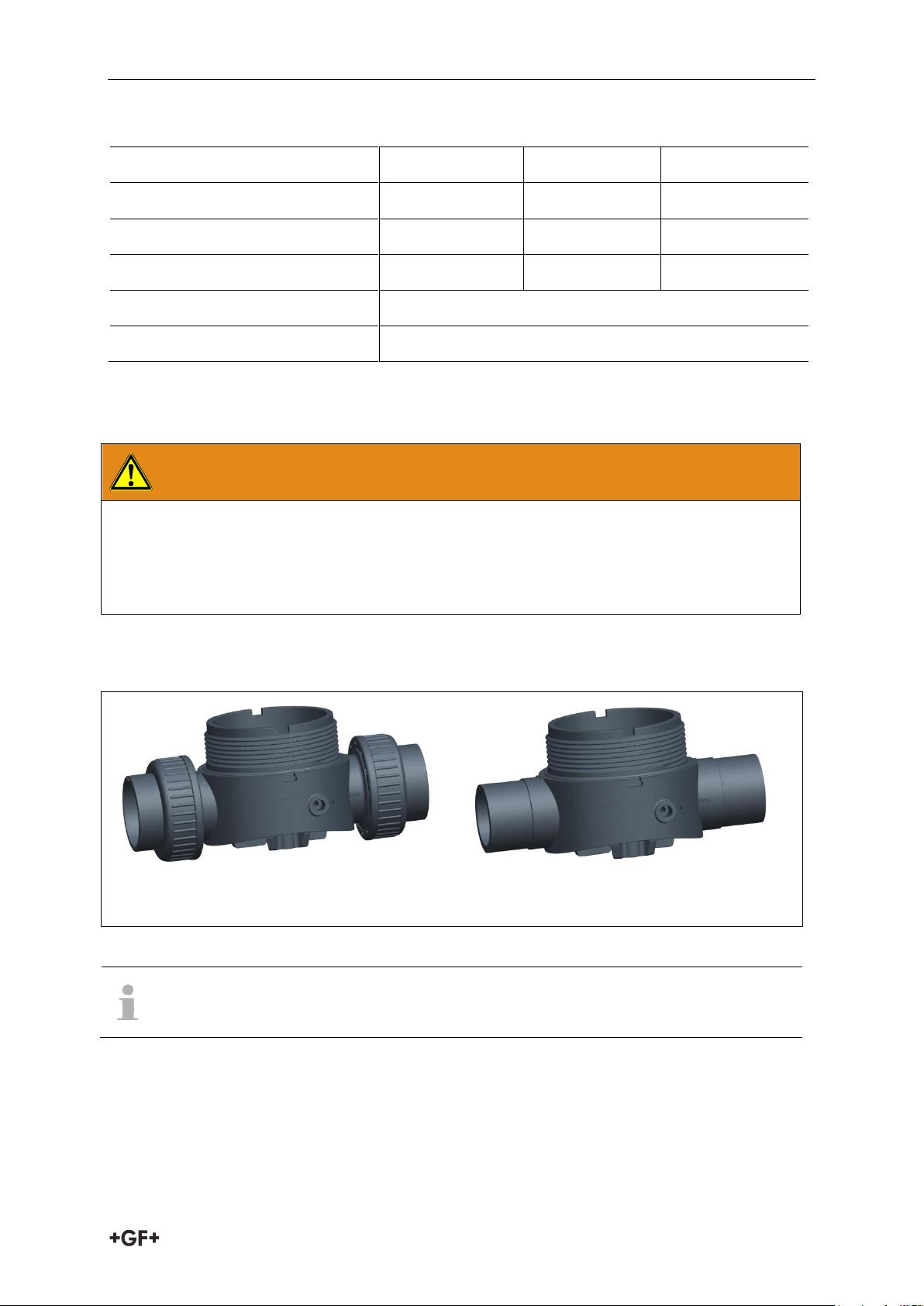
Connection: radial installation and removal
Connection: spigot ends
Pressure reducing valves type 582/pressure retaining valves type 586 are supplied
with released spring.
8 Required tools
9 Installation
The valve bodies are suited for various connection types:
35
Page 11
Installation Instruction manual
Ensure that pressure reducing valve type 582/pressure retaining valve type 586 is suited
for operating conditions, see label.
Check pressure reducing valve type 582/pressure retaining valve type 586 on damages
before installation. Do not use any damaged or faulty product.
Ensure that the installation of pressure reducing valve type 582/pressure retaining valve
type 586 is carried out without tension.
In order to ensure an optimum flow rate, ensure that
- pressure reducing valve type 582/pressure retaining valve type 586 is installed
in a section of the pipeline that is not subjected to turbulent flow and that
- bends, restrictions, shut-off devices have a minimum distance of 10 x DN from
pressure reducing valve type 582/pressure retaining valve type 586.
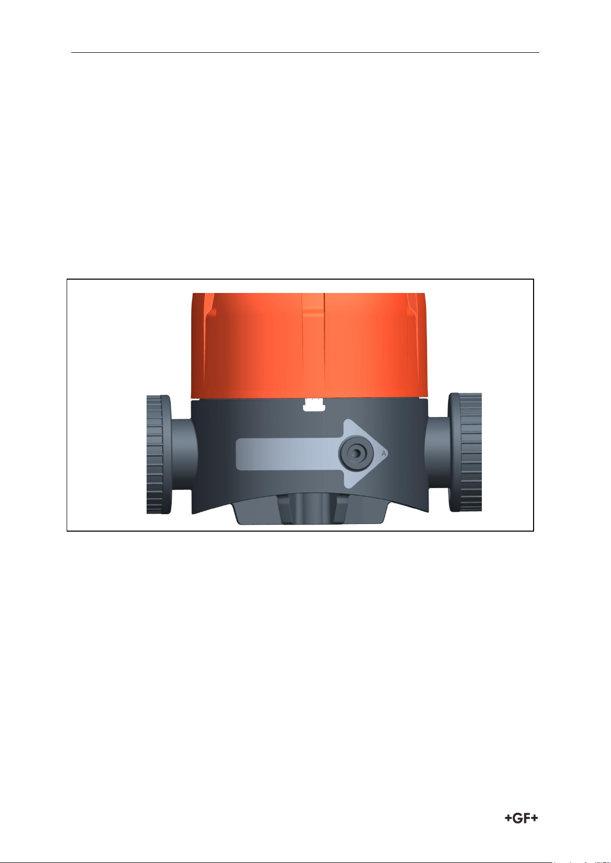
Observe the flow direction, see arrow on body (Fig. 1)
Fig. 1
Observe connection types, see versions of „radial installation and removal“ and „spigot
ends“.
36
Page 12
Instruction manual Installation
In order to protect against soiling and premature wear and tear by erosion, we
recommend installing a strainer on the inlet side of pressure reducing valve type
582/pressure retaining valve type 586.
Type „Radial installation and removal“:
Loosen the coupling nut and slide it on the intended pipe end.
Connect the connection parts with the pipe ends. For instructions concerning the different
connection types, see planning fundamentals.
Put pressure reducing valve type 582/pressure retaining valve type 586 between the
connection parts.
Tighten the coupling nuts by hand.
„Spigot ends“:
If adapted to flange version, observe the tightening torques of the flanges, see „Georg
Fischer planning fundamentals“.
Cemented connection
Only join identical materials.
After the curing time of the joint has elapsed, rinse the pipe section as quickly as possible
with pressure-less water, see Chapter „Jointing techniques” in the „Georg Fischer
planning fundamentals”
Welded connection
Only join identical materials, see Chapter „Jointing techniques” in the „Georg Fischer
planning fundamentals”.
37
Page 13
Operation Instruction manual
1 ½
Umdrehungen
10 Operation
10.1 Pressure test
Ensure that the test pressure does not exceed 1.1 times the max. set back pressure.
10.2 Setting the working pressure
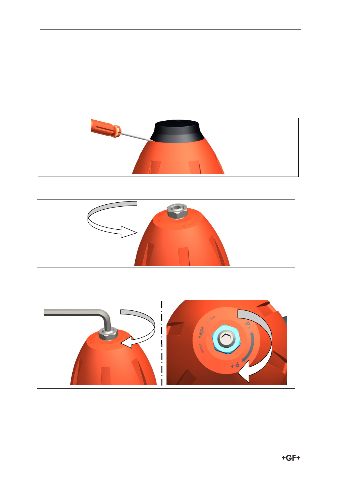
Remove the cap from the bonnet assembly (top part), see Fig. 2. To do so, position the
screw driver in the notch of the cap.
Fig. 2
Loosen the locking nut, see Fig. 3
Fig. 3
In order to increase the setpoint value: Tense the spring. To do so, turn the spindle
clockwise, see Fig. 4
Fig. 4
38
Page 14
Instruction manual Operation
CAUTION
Displacement of the set point value of pressure reducing valve type 582/
pressure retaining valve type 586 due to wrong locking.
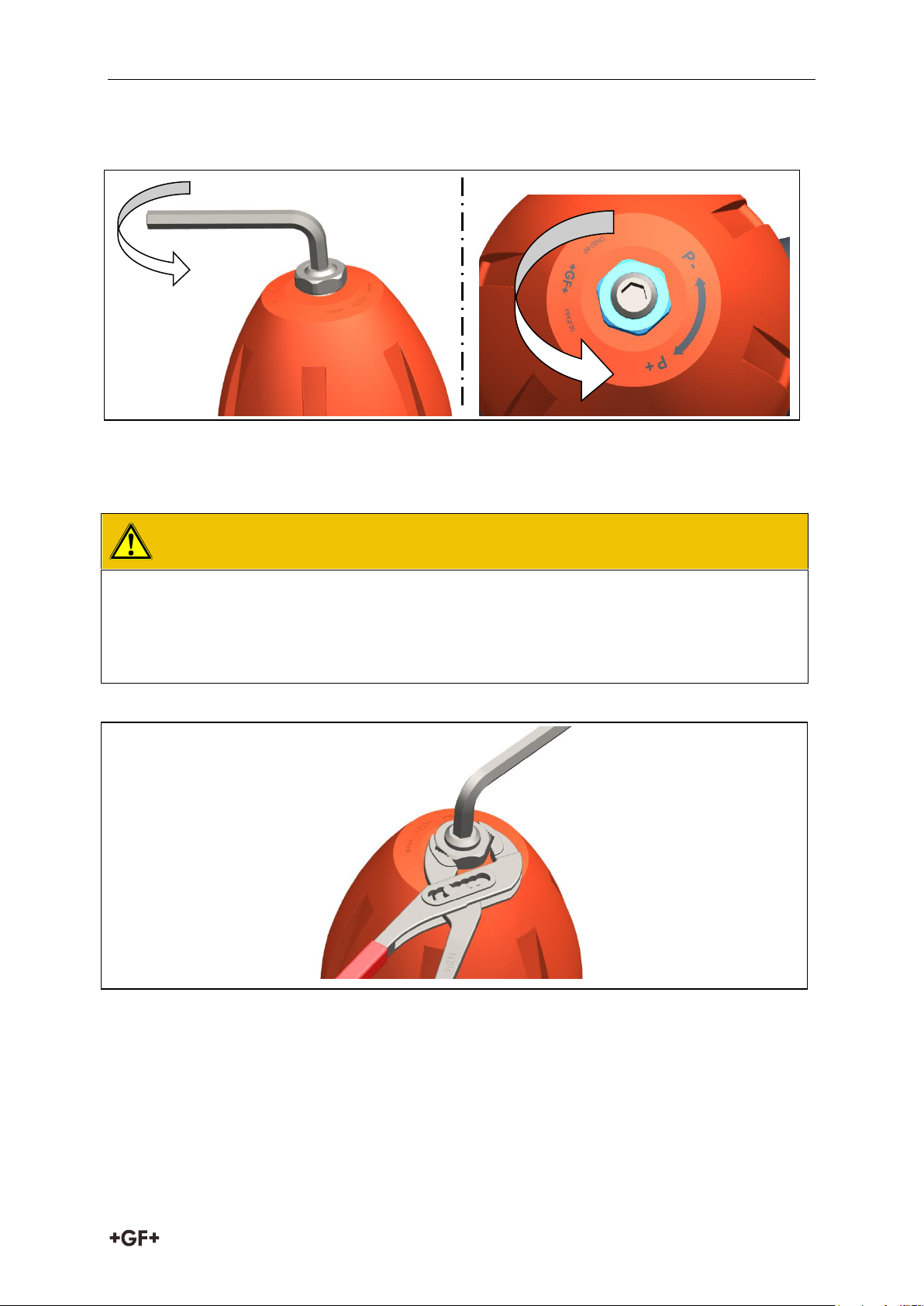
Fix the spindle with Allen wrench and simultaneously tighten the locking nut
with a suited tool, see Fig 6
In order to decrease the set point value: Relax the spring. To do so, turn the spindle
counterclockwise, see Fig. 5
Fig. 5
Ensure that the set point value is set. To do so, read the set point value at the manometer
or the corresponding indicator.
Fig. 6
Put the cap onto the bonnet assembly (top part).
39
Page 15
Maintenance Instruction manual
WARNING
Risk of injury due to uncontrolled evasion of the medium!
If the pressure was not relieved completely, the medium can evade uncontrolled.
Completely relieve pressure in the pipes prior to
dismounting/maintenance/dismantling.
In case of harmful, flammable, or explosive media: Completely empty and rinse
pipe prior to dismounting. Pay attention to potential residues.
Make sure that the medium is caught safely with the appropriate measures.
Difficult opening, due to pretensioned spring.
Make sure that the spring is
completely relaxed before opening the bonnet assembly (top part). To do so, turn the
spindle counterclockwise (P-), up to the end position.
CAUTION
Risk of injury and missing product quality through use of spare parts that have
not been provided by GF Piping Systems!
Only use the listed spare parts, see Chapter List of Spare Parts.
Maintenance interval
Maintenance activity
regular
Check sealing element, piston, diaphragm on
functionality and replace, if necessary
regular
Check tightness of housing, pipe connection and control
line.
regular
Clean the inner body
11 Maintenance
Set maintenance intervals as per the conditions of use (e.g. actuating cycles, medium,
ambient temperature).
As part of the regular system inspection, carry out the following maintenance activities.
40
Page 16
Instruction manual Maintenance
11.1 Replacing diaphragm and O-ring
Remove the valve from the pipeline and bring it into horizontal position.
11.1.1 Disassembly
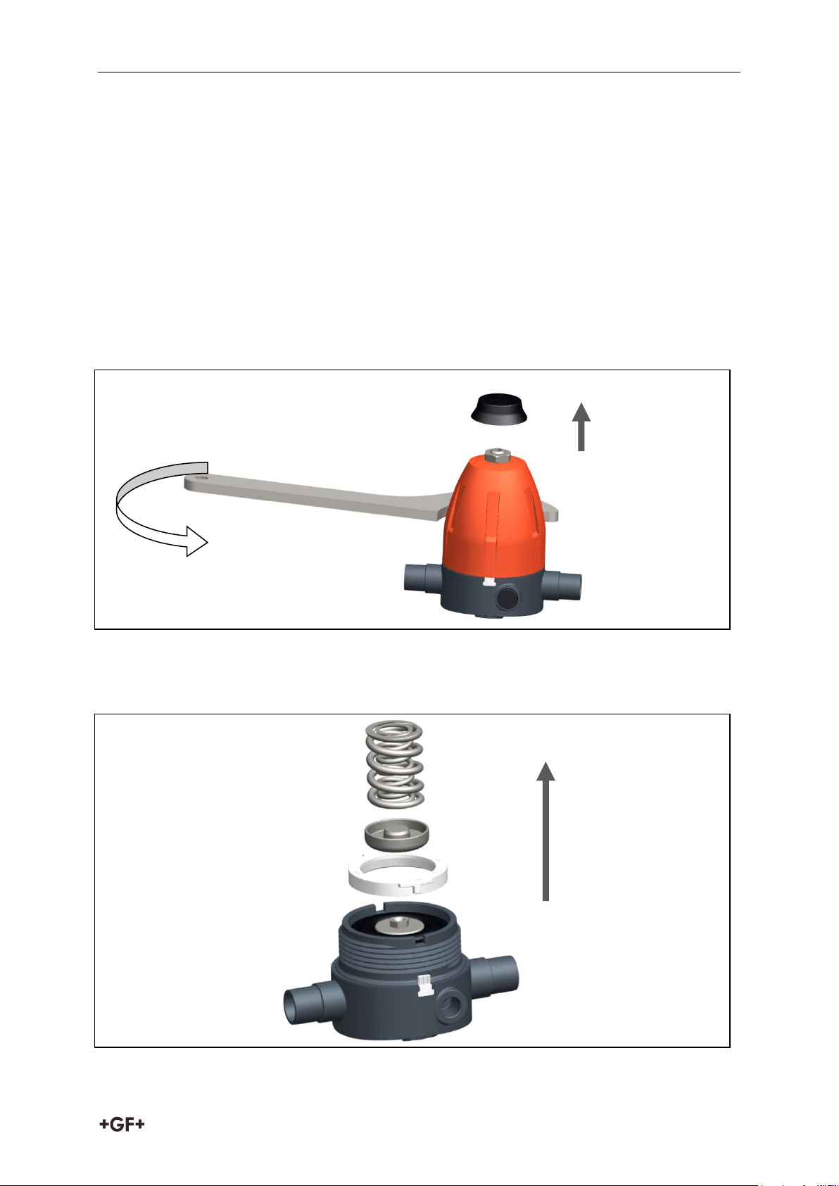
Prior to dismantling: Mark the position of bonnet assembly (top part) to body on the
housing.
Remove the cap from the bonnet assembly (top part), see Fig. 2. To do so, use a screw
driver.
Relax the spring. To do so, turn the spindle counterclockwise (P-), up to the end position.
Fix the body with a suited tool and loosen the bonnet assembly (top part). To do so, turn
the bonnet assembly (top part) counterclockwise, see Fig. 7. During this, the seal sticker
will be broken.
Fig. 7
Remove Pressure piece, springs and retaining ring, see Fig. 8
Optional version 0.3 - 3 bar (4 - 44 psi): one spring
Fig. 8
41
Page 17
Maintenance Instruction manual
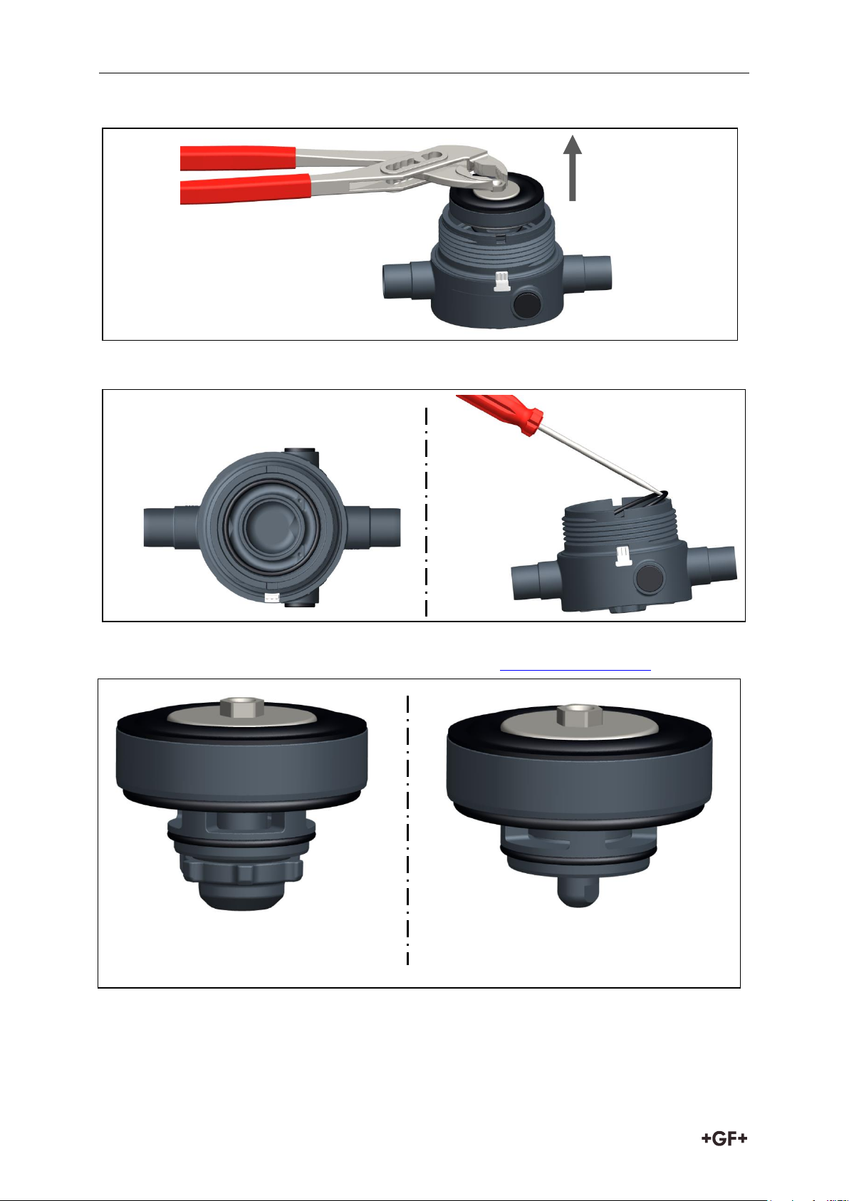
Cartridge for pressure
reducing valve type 582
Cartridge for pressure
retaining valve type 586
Remove cartridge from body with suited tool (e.g. pliers), see Fig. 9
Fig. 9
Remove 2 O-rings from body, see Fig. 10
Fig. 10
In order to replace diaphragm: Replace cartridge, see Chapter “spare parts”
Fig. 11
42
Page 18
Instruction manual Maintenance
11.1.2 Assembly
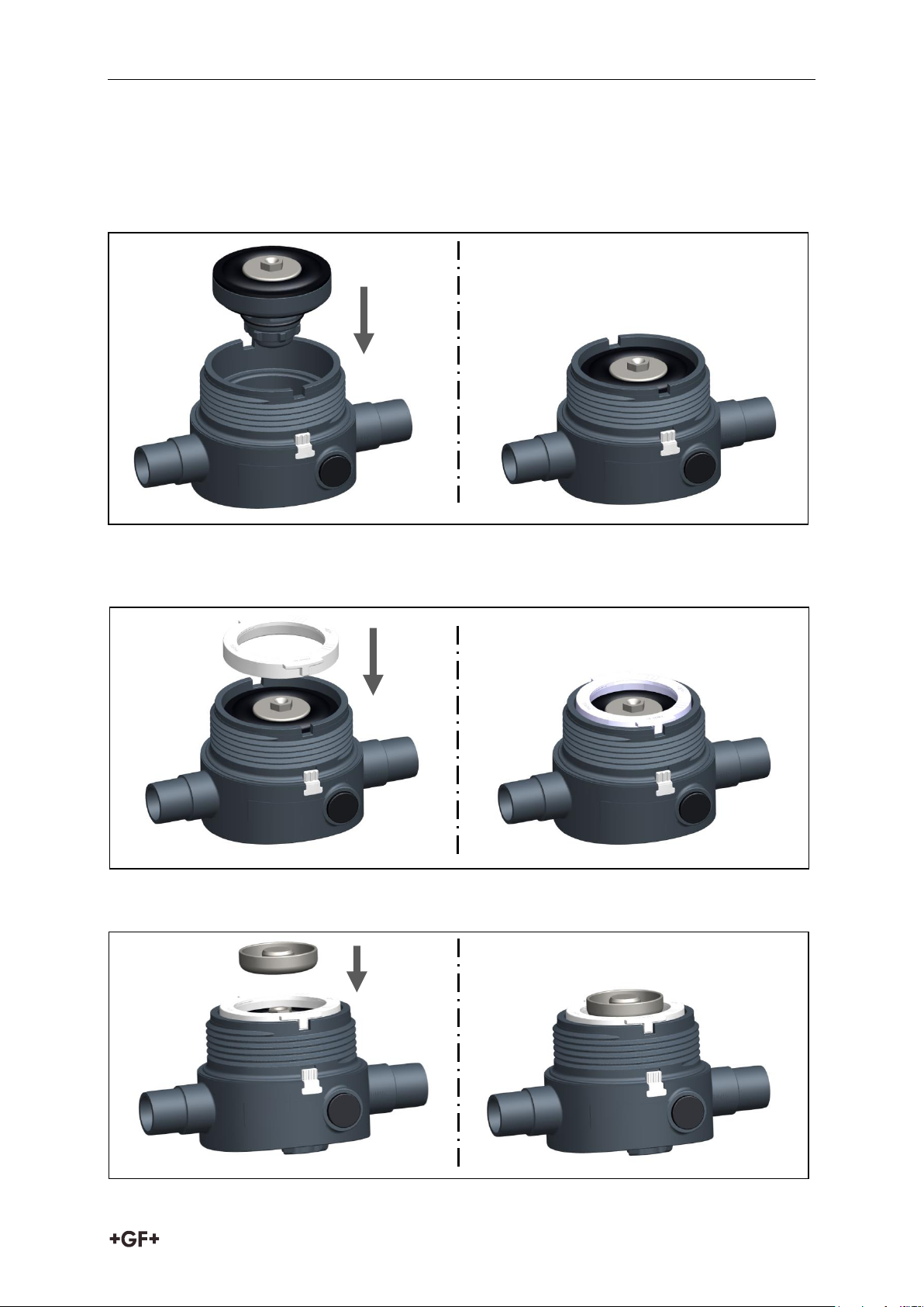
Ensure that 2 O-rings sit correctly in the body.
Position the cartridge in the body and push in, see Fig. 12
Replace the index plate in case of valve type or elastomer change
Fig. 12
Place the retaining ring. During this, ensure that both projections of the retaining ring lie
in the notches of the body, see Fig. 13
Fig. 13
Put the Pressure piece on the cartridge, see Fig 14
Fig. 14
43
Page 19
Maintenance Instruction manual
DN 10/15
DN 20/25
DN 32/40/50
50Nm
70Nm
120Nm
DN 10/15
DN 20/25
DN 32/40/50
0.5 mm
0.6 mm
0.9 mm
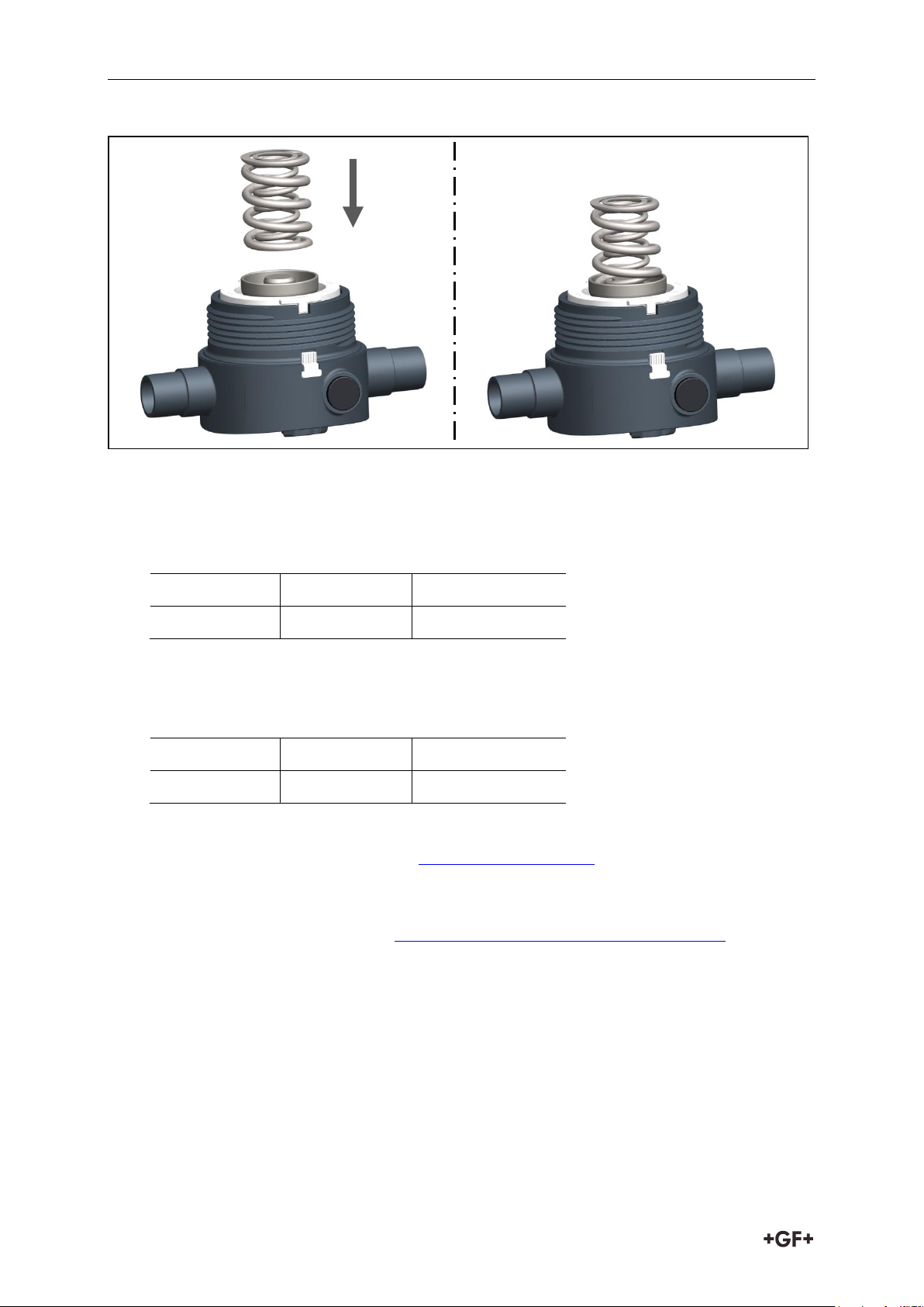
Put the springs on the Pressure piece, see Fig 15
Fig. 15
Put the bonnet assembly (top part) onto the body.
Fix the body and tighten up to the marking/old seal sticker (see Chapter 11.1.1) +20°:
Clearance check between top part and body
Install the valve into the pipeline, see Chapter 9 „Installation“
Fix the spindle with Allen wrench and simultaneously tighten the locking nut with a suited
tool.
Setting the working pressure, see Chapter 10.2 "Setting the working pressure"
44
Page 20
Instruction manual Maintenance
Pressure reducing valve
type 582
Pressure retaining valve
type 586
Example: Pressure reducing valve type 582
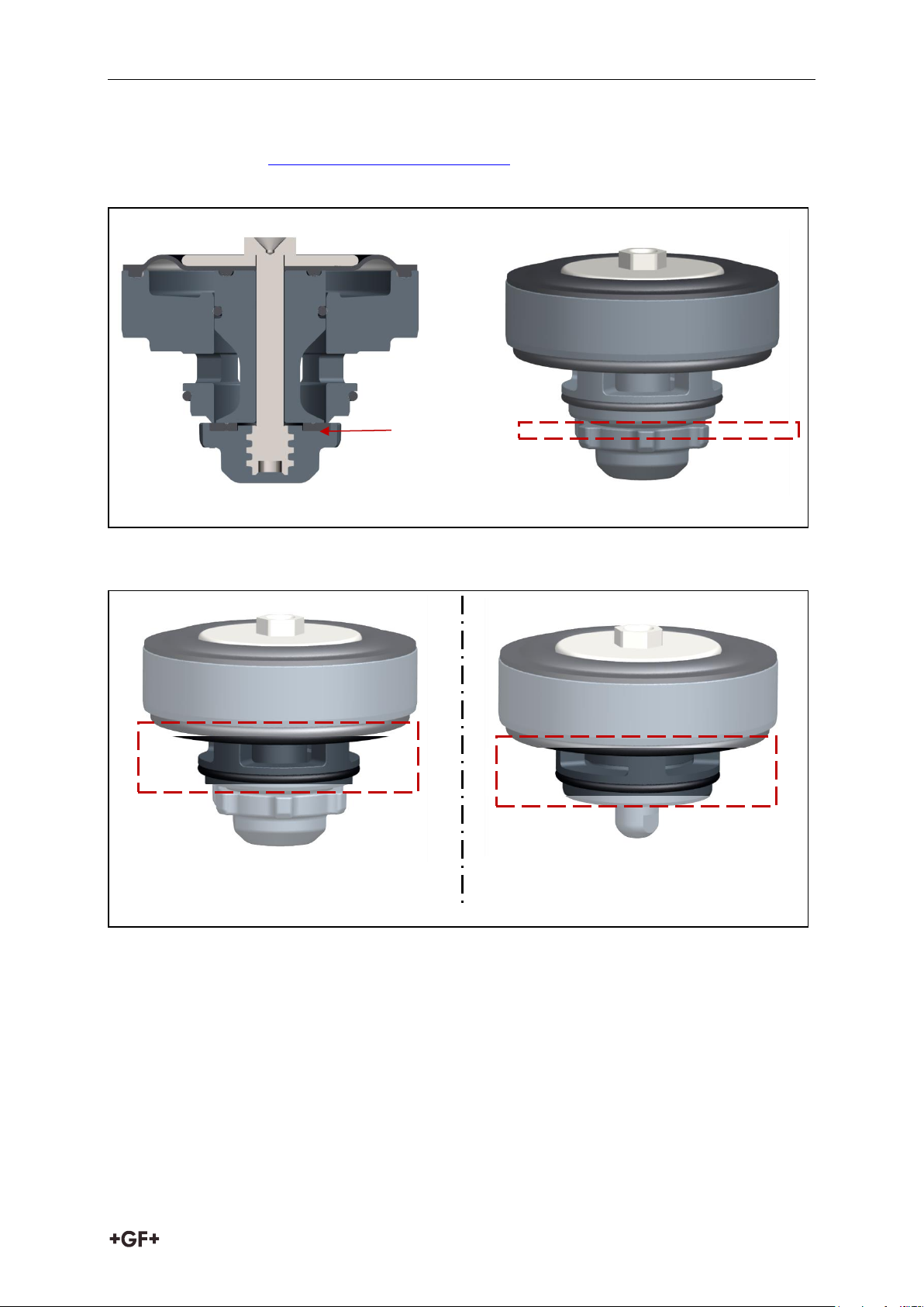
Seat gasket
11.2 Cleaning the inner body
Dismantling, see Chapter 11.1.1 "Disassembly"
Check and clean the area of the seat gasket, see Fig. 16
Fig. 16
Clean the drill holes of the inner housing, see Fig. 17
Fig. 17
45
Page 21
Troubleshooting Instruction manual
Fault
Possible cause
Troubleshooting
Leak at pipe
Leaking connections
Check bonding or welding
and repair, if necessary
Check gaskets and
replace, if necessary
Leak between top part and
body
Retaining ring not
correctly inserted
Position the retaining ring
so both projections of the
retaining ring lie in the
notches of the body
Bonnet assembly
(top part) loose
Retighten bonnet
assembly (top part)
Leak at bonnet assembly
(top part)
Piston screw loose
Retighten piston screw
Diaphragm damaged
Replace diaphragm,
see Chapter 11
Control element
(diaphragm, piston,
sealing element) defective
Replace cartridge.
Set point value not
reached
(only valid for pressure
reducing valve type 582)
Foreign body jammed,
preventing tight closing
Tense the spring, so the
valve opens and the
foreign body is flushed out
(caution: pressure
increase)
Impure function parts
Clean pressure reducing
valve type 582, see
Chapter 11.2
Inertia too high, set point
value not reached
Valve undersized
Check valve dimensioning
(kvs value)
Valve does not react to
compressed air
Valve is not dimensioned
for compressed air, and
therefore has no
compressed air
connection
Remove compressed air
and select other valve
(e.g. pneumatic diaphragm
valve) for the application
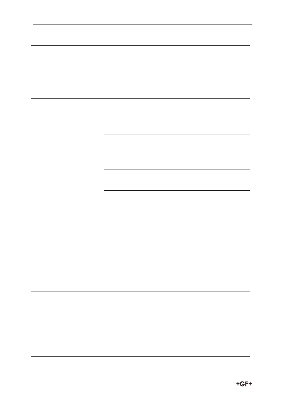
12 Troubleshooting
46
Page 22
Instruction manual Troubleshooting
Fault
Possible cause
Troubleshooting
Loud noise
Valve oversized. Thus, the
valve only opens a
minimum, leading to
vibrations
Check valve dimensioning
(kvs value)
Valve undersized. This
results in excessive flow
velocities inside the valve
Check valve dimensioning
(kvs value)
Excessive damage of
pressure reducing valve
type 582/pressure
retaining valve type 586
Dirty medium, corrosion
deposits or foreign
matter.
Install strainer
Manometer does not
indicate anything
Manometer defective
Replace manometer
Buffer medium escaped
from the manometer
adaptor
Check manometer adaptor
and replace, if necessary
Manometer stays on a
constant value
Manometer defective
Replace manometer
Drill holes in the cartridge
clogged
Clean cartridge, see
Chapter 11.2 „Cleaning the
inner body“
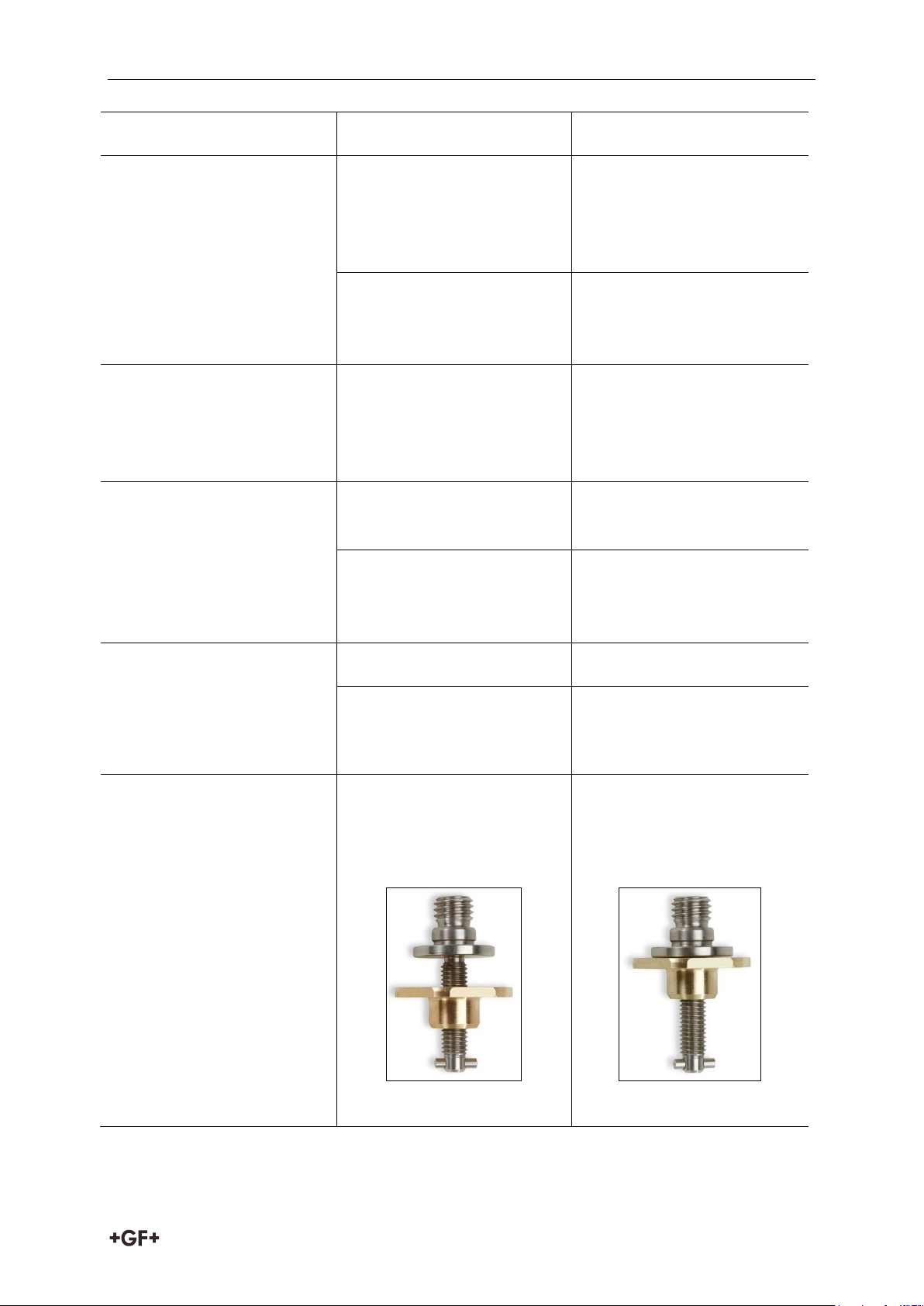
Bonnet assembly (top
part) cannot be screwed
onto the body
Spring not relieved
Spring cap is not in the
end stop, see Fig. 18
Screw spring cap into the
end position, see Fig 19
Fig.18
Fig.19
47
Page 23
Spare Parts Instruction manual
Designation
Article number
DN 10/15
DN 20/25
DN 32/40/50
Hook wrench
198 806 451
198 806 452
198 806 453
Manometer adaptor
198 806 650
Manometer brass
198 806 651
Manometer stainless steel
198 806 652
Manometer sealing plug
198 806 653
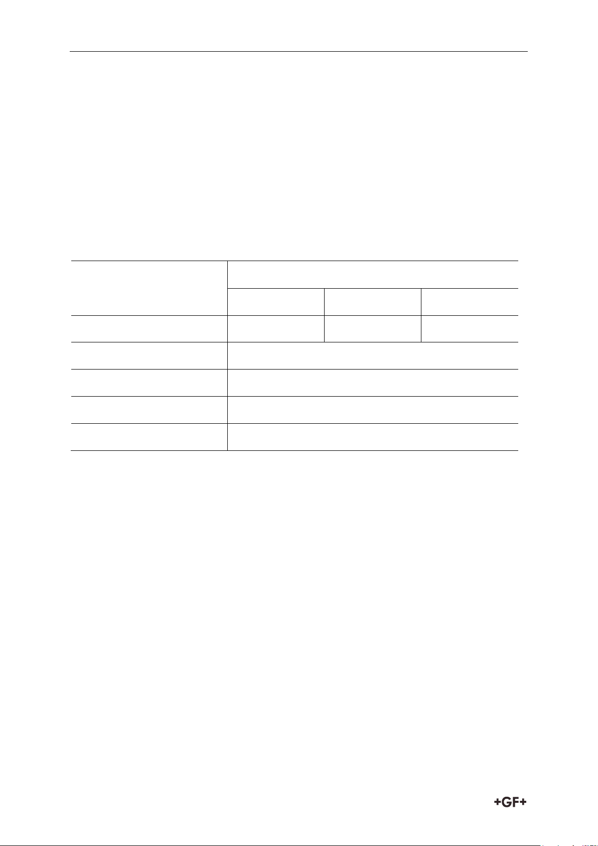
13 Spare Parts
Order spare parts as follows:
Identify valve type and sealing material by means of index plate, see Chapter 6.1. Sealing
material.
Read DN size at body.
Read designation of spare part, see Chapter 4.1 or 4.2.
Send the order with these details and the required quantity to the agency of GF Piping
Systems.
14 Accessories
15 Disposal
Before disposing of the different materials, separate them by recyclables, normal waste
and special waste.
Comply with local legal regulations and provisions when recycling or disposing of the
product, the individual components and the packaging.
Comply with national regulations, standards and directives.
48
Page 24
Instruction manual EC Manufacturer's declaration
WARNING
Parts of the product may be contaminated with media that are harmful for the
health and the environment. Therefore, a simple cleaning is not sufficient!
Danger of personal injury and damage to the environment caused by those media.
Prior to disposing of the product:
Collect leaking media and dispose of according to the local regulations.
Consult the safety data sheet.
Neutralize possible media residues in the product.
Separate materials (plastics, metals etc.) and dispose of according to the local
regulations.
If you have questions regarding the disposal of your product, please contact your national GF
Piping Systems representative.
16 EC Manufacturer's declaration
The manufacturer, Georg Fischer Rohrleitungssysteme AG, 8201 Schaffhausen (Switzerland),
declares that, due to the exclusion of the use for flammable or gaseous media and because of
their nominal diameter and pressure level, the pressure regulating valves are not subject to
Pressure Equipment Directive 2014/68/EU.
Changes to the pressure regulating valve that could affect the stated technical specifications
and the intended use, void this manufacturer's declaration.
Name: Bastian Lübke
Position: R&D Manager Georg Fischer Piping Systems
Date: 2017-02-22
49
 Loading...