

Page 1
Signet 2450 Pressure Sensor
-XU
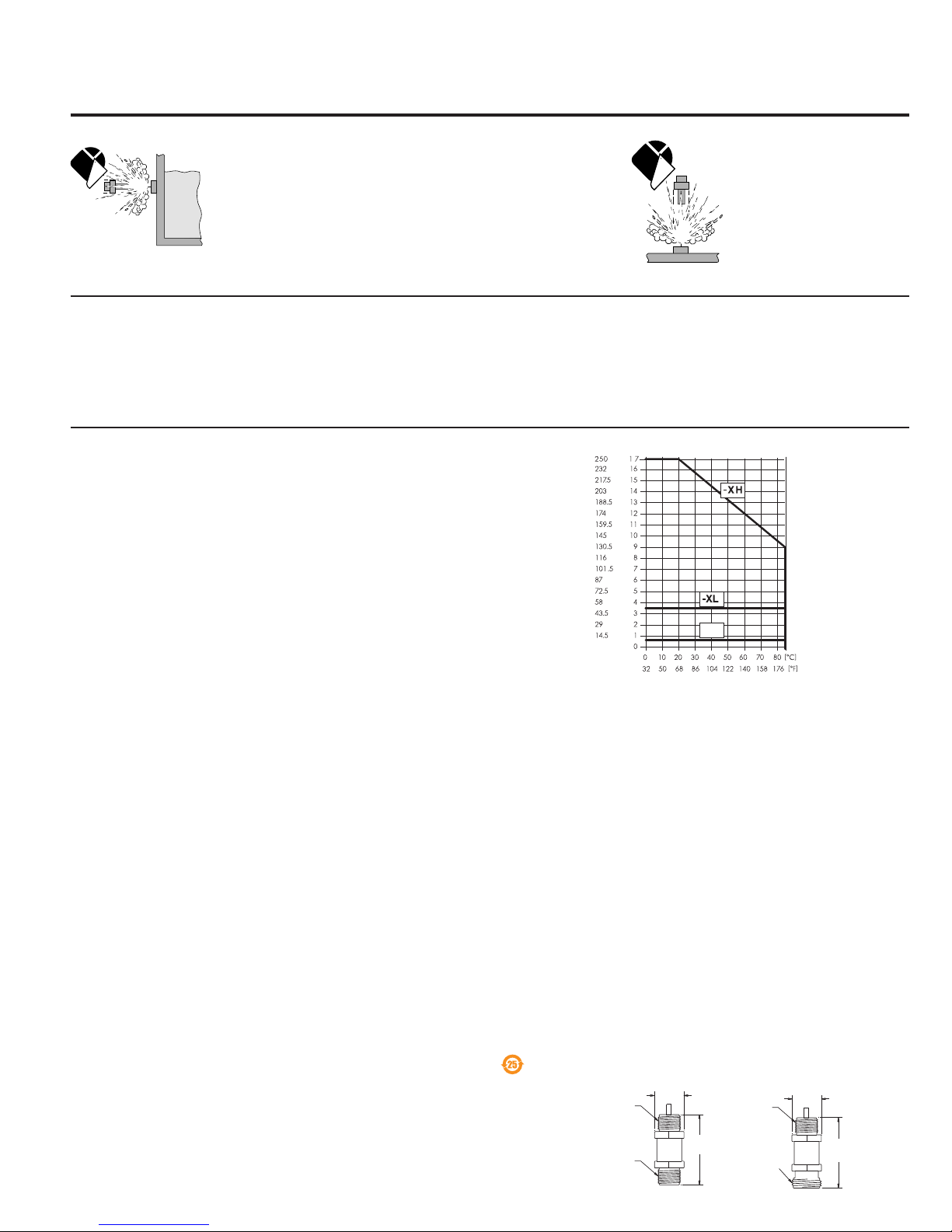
Application Limits
Temperature
Pressure [psi]
Pressure [bar]
*3-2450.090-1*
3-2450.090-1 Rev. H 2/11 English
English
Safety Instructions
1. Prior to installation or removal:
• Depressurize and vent system
• Drain below sensor level
2. Confi rm chemical compatibility before use.
3. Do not exceed maximum temperature/pressure specifi cations.
4. Wear safety goggles or faceshield during installation/service.
5. Do not alter product construction.
6. Dispose of properly; DO NOT INCINERATE!
USE THE ATTACHED ADHESIVE LABEL TO PRESERVE THE SAFETY INSTRUCTIONS!
1. Description
The 2450 Pressure Sensor has a one-piece injection molded PVDF body and ceramic diaphragm for superior compatibility in corrosive
liquids. These sensors are available with Digital (S
ranges for optimal measurement resolution. Built-in temperature compensation provides outstanding accuracy over a wide operating
range. Versions with 1/2 in. union process connection are best suited for in-line installations.
Integral adapters (sold separately) may be used to create a compact assembly with fi eld mount versions of the 8250 Level Transmitter
and the 8450 Pressure Transmitter.
2. Specifi cations
General
Compatibility: 2450 Digital (S3L) output models:
8250, 8450, 8900
2450 Current output models: PLC
Wetted materials:
• Sensor housing: PVDF
• Diaphragm: Ceramic
• Seal: FPM
Process connection:
• -1X, -5X:
• -3X, -7X:
where X = U, L, or H
Rear connection:
Cable type: 3 cond + shield, 22 AWG
Standard cable length:
• 2450-1x, -3x, 5x, 7x: 4.6 m (15 ft)
Sensor Accuracy: ±1% of full scale @ 25 °C
Thermal sensitivity shift: ±0.03% of full scale per °C
Shipping weight:
• 2450-1x, 2450-3x 0.3 kg (0.65 lb)
Electrical
Power Requirements:
• Digital (S
3
L) models: 5 to 6.5 VDC ±10%, <1.5 mA
• 4 to 20 mA models: 12 to 24 VDC ±10% regulated
Short circuit & reverse polarity protected
3
Digital (S
L) output:
• Type: Serial ASCII, TTL level 9600 bps
• Accuracy: ±1% of full scale @ 25 °C
• Repeatability: ±0.5% of full scale
• Resolution: 0.01 psi (0.001 psi for -XU)
• Update rate: <100 ms
4 to 20 mA output:
• Accuracy: ±32 μA
• Repeatability: ±0.5% of full scale
• Resolution: <5 μA
• Span: Field-scaleable
(see section 6.3 for factory settings)
• Max loop impedance: 100 @ 12 V
325 @ 18 V
600 @ 24 V
• Update rate: <100 ms
3
/4 in. NPT male thread, where X = L, H
1
/2 in. Union male thread,
3
/4 in. NPT male thread
Table of Contents
1. Description
2. Specifi cations
3. Installation
4. (S
3
L) wiring
5. 4 to 20 mA wiring
6. 4 to 20 mA span
adjustment
7. Ordering information
3
L) digital output or fi eld-scaleable 4 to 20 mA output. Select from three (3) pressure
• Operating range (Max. pressure for accuracy specifi cations):
-XU 0 to 0.7 bar (0 to 10 psig)
-XL 0 to 3.4 bar (0 to 50 psig
-XH 0 to 17.2 bar (0 to 250 psig)
• Vacuum range:
-XU -0.1 to 0.7 (-1.5 to 10 psi)
-XL -0.41 to 3.4 bar (-6 to 50 psi)
-XH -0.96 to 17.2 bar (-14.6 to 250 psi)
• Proof pressure (Max. pressure without damage):
-XU 1.4 bar (20 psig)
-XL 5.2 bar (75 psig)
-XH 20.7 bar (300 psig)
Environmental
• Relative humidity: 0 to 95% (Non-condensing)
• Storage temperature: -20 °C to 100 °C (-4 °F to 212 °F)
• Operating temperature: -15 ºC to 85 °C (5 °F to 185 °F)
Standards and Approvals
• CE
• Manufactured under ISO 9001 and ISO 14001
China RoHS (Go to www.gfsignet.com for details)
Dimensions
¾ in. NPT
¾ in. NPT
34 mm
(1.34 in.)
3-2450-1X, -5X
81 mm
(3.18 in.)
¾ in. NPT
½ in.
Male
Union
3-2450-3X, -7X
34 mm
(1.34 in.)
81 mm
(3.18 in.)
Page 2
3. Installation
Diaphragm
Capillary Tube
Cable gland
Reducer coupling
3-8052
Integral mount kit
3-8450
*
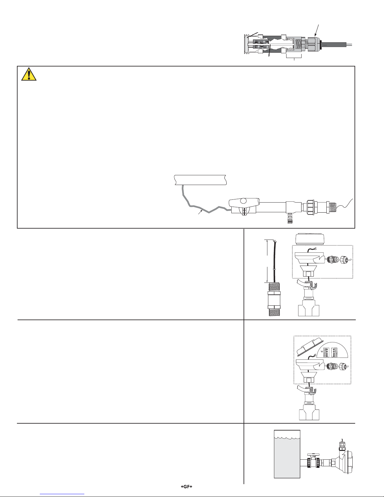
• Signet 2450 Pressure Sensors are gauge pressure sensors. Gauge pressure
sensors measure the difference in pressure between the process on one side of a
diaphragm and the atmospheric pressure on the opposite side of the diaphragm.
A tiny capillary tube inside the sensor body is used to ensure that the back of the
diaphragm remains at atmospheric pressure. If moisture is allowed to propagate
down this tube to the rear of the diaphragm, the sensor may be damaged.
Important Installation Recommendations
• The ceramic diaphragm is subject to breakage by over-pressure conditions or mechanical contact.
HANDLE WITH CARE. Do not attempt to test the sensor by pressing on the diaphragm.
• Short duration pressure pulses or shocks, called ‘‘water hammer’’ are generated by a rapid change in fl ow rate caused by the
operation of system components such as compressors, pumps, pistons and valves. Water hammer can reach pressure levels
far exceeding the over pressure rating of our pressure sensors and damage the ceramic diaphragm.
• A pressure snubber is a device for slowing the rate of change of system fl ow. Installation of a properly sized snubber at or
near the input of a pressure sensor will protect it from water hammer damage. Snubbers are available through plumbing and
instrumentation dealers.
• When threading the sensor into a piping system, any backpressure can damage the ceramic diaphragm. Open nearby valves
to relieve any backpressure while threading the sensor into the pipe.
• If the nearby valves cannot be open while threading the
sensor into the pipe, a bleed valve can be installed to
avoid over pressure.
• Make sure there are no air bubbles in the pipe,
particularly if a long and fl exible hose is used to tap into
the process pipe. Air bubbles could cause reading fl uctuation and errors.
The compact integral assembly can be assembled by using thefollowing directions:
3.1 Integral Assembly Sensor Modifi cation
• Modify sensor part number 3-2450 per fi gure 1.
• Apply sealant or PTFE tape to the process connection threads per fi gure 2, after
inspecting threads to ensure integrity. Do not install a sensor with damaged threads.
• Thread the sensor into the 3-8052 mounting kit.
• Tighten the sensor 1
1
/2 turns past fi nger tight into the process connection.
• Install 8450 transmitter (refer to 8450 manual for wiring info).
• The 3-8052 Integral kit includes:
• 3/4 in. NPT process connection
• 3-9000.392-1 liquid tight connector, 1/2 in. NPT
• Conduit base to attach 8450.
Process Pipe
F
l
e
x
i
b
l
e
No Air Bubbles
Main Valve Closed
h
o
s
e
Bleed Valve Open
Integral assembly
152 mm
(6 in.)
Figure 1
Figure 2
3.2 In-line Remote Assembly
he optional 3-8052-1 Integral Junction box with 3/4 in. process connection offers a convenient
T
Remote assembly
terminal point to extend the 2450 cable over a distance greater than 4.6 m (15 ft).
• The kit includes:
3
•
/4 in. NPT process connection
• Conduit base and cap with junction terminals
• 3-9000.392-1 liquid tight connector,
1
/2 in. NPT
To extend the wires longer than 4.6 m (15 ft)
• Modify sensor 3-2450 as described in fi gure 1.
• Terminate the three wires to the terminal board located in the cap assembly.
• Add customer supplied wire to extend the cable.
• Terminate to the transmitter or the 4 to 20 mA input device.
Figure 3
• Apply sealant or PTFE tape to the process connection threads per fi gure 3, after inspecting
threads to ensure integrity. Do not install a sensor with damaged threads.
• Tighten the sensor 1
1
/2 turns past fi nger tight into the process connection.
3.3 Tank Installation Options
Submersible:
• Refer to the GF product 3-2250-XX for submersible installations.
(Refer to Signet Submersion Kit 3-0000.707)
Side Tank Mount:
• Install GF ball valve to allow isolation of the sensor for maintenance.
• It is recommended that a 3-8052-1 kit be used to protect the back end of the sensor.
WARNING: Exposing the sensor body to elevated temperature that are different that the tank
fl uid temperatures will cause inaccurate reading.
2 2450 Pressure Sensor
BLK
+
RED
WHT
-
S
3-8052-1
Integral junction box,
3/4 in. NPT
*
SHLD
*
Page 3
3.4 1/2 Inch Male Union Installation
+5 VDC
data
Signal Ground
+
S
-
BLK
RED
WHT
SHLD
BLK
RED
WHT
SHLD
+
S
-
Temperature
T3 29.5 ºC
Signet Multi-Parameter
Controller
C1 2.50 µS/cm
F2 58.43 GPM
Relay 1
Relay 2
ENTER
3-8052
3-8050.531
(S3L)
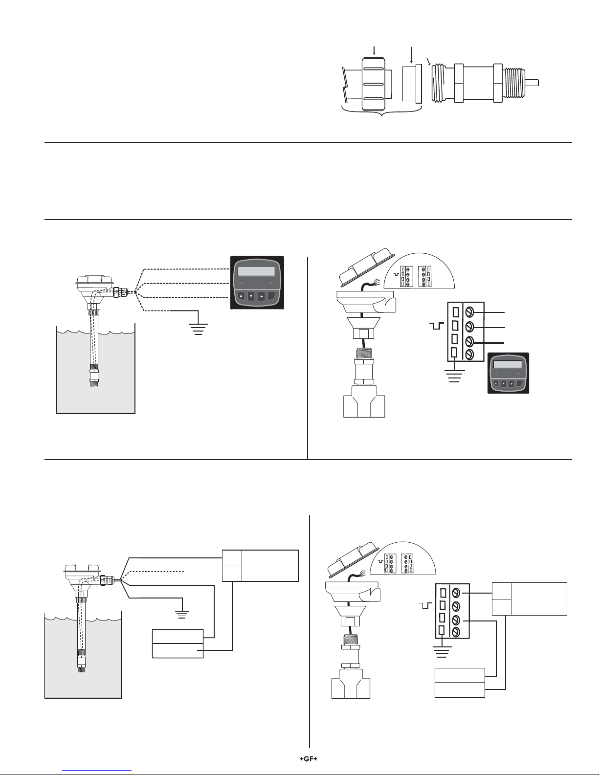
• The 2450-3X, the 2450-4X and the 2450-7X sensors have a
union-style process connection. To assemble:
Union Nut
End Connector
O-Ring
1. Slide union nut onto pipe or fl exible tubing.
2. Install end connectors.
3. Hand-tighten union nut to secure.
4. A
3
/4 in. NPT thread is provided to attach a cable gland or
conduit.
5. Refer to Signet Measurement and Instrumentation Product
Pipe
not supplied
Sensor
Catalogue (page 205) for ordering information.
4. Digital (S3L) wiring
• All models of the 2450 provide Digital (S3L) output when powered with 5 VDC.
• Connecting the SHIELD to a direct Earth ground may reduce electrical noise interference.
• The maximum Digital (S3L) cable length is dependent upon the instrument to which the sensor is connected.
Consult the instrument manual for details.
4.1 Digital (S3L) With No Junction Box 4.2 Digital (S3L) With Junction Box
Cable gland
or conduit
connection
3-8050.521
3-8052
Black
Red
White
Shield
+ 5 VDC
(S3L)
data
Signal ground
Optional
Earth Ground
Temperature
C1 2.50 µS/cm
T3 29.5 ºC
F2 58.43 GPM
Signet Multi-Parameter
Controller
Relay 1
Relay 2
ENTER
Optional
Earth ground
3
• Connect the 2450 cable directly to Digital (S
L) I/O terminals. • When the 2450 includes a junction box, connect the 2450
terminals to any Digital (S3L) I/O port as shown.
5. 4 to 20 mA Loop Wiring
• The 2450-5X and 2450-7X models provide a 4 to 20 mA loop output when powered with 24 VDC.
• Connecting the SHIELD to a direct Earth ground may reduce electrical noise interference.
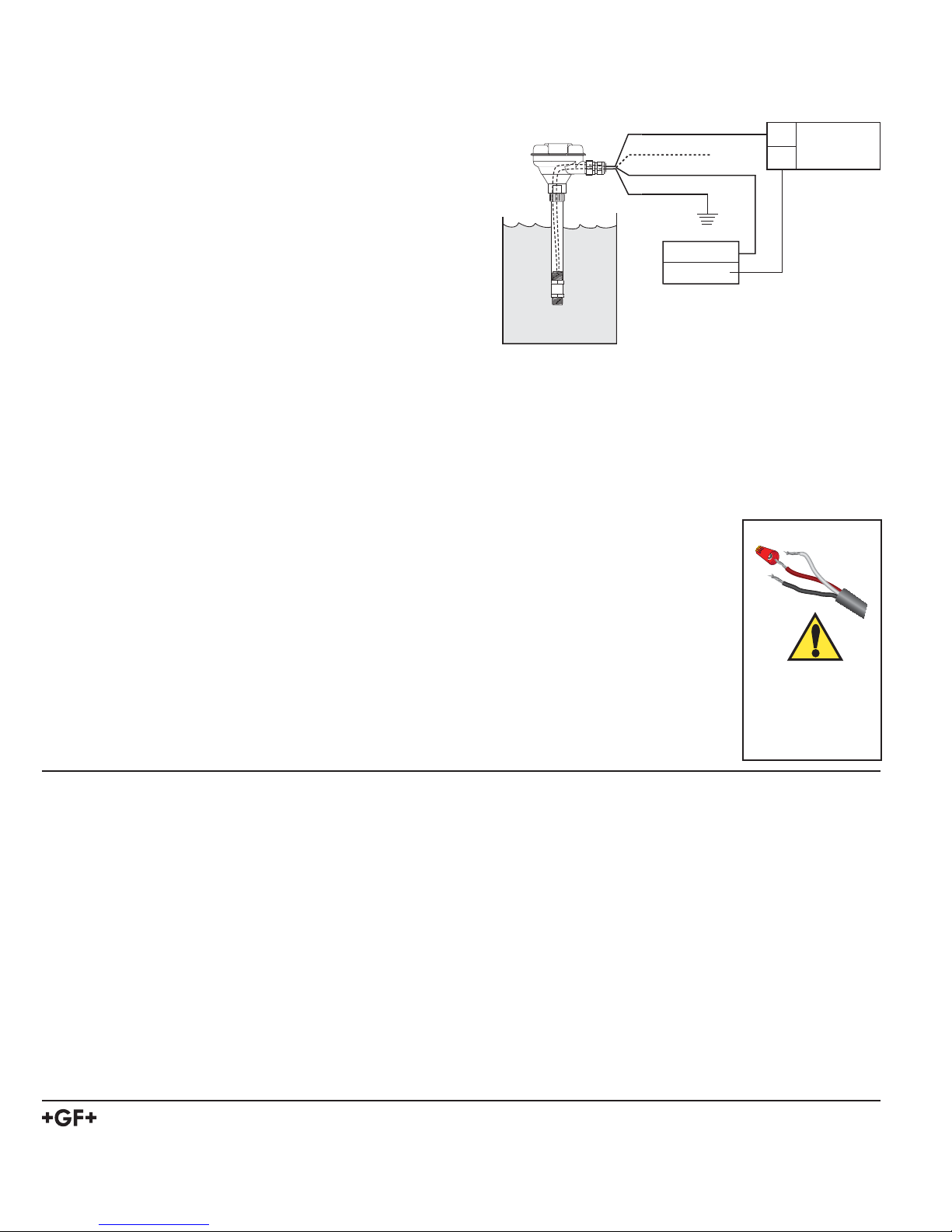
• Red wire is not used, do not remove the heat shrink. See Section 6, 4 to 20 mA span adjustment.
5.1 Current Loop With No Junction Box
Black (Loop +)
Red
White (Loop - )
Shield
*
Optional
Earth Ground
Loop Input
Loop Input
4 to 20 mA loop
monitor
+
-
+
-
Power Supply
DC 12 - 24 V
3-8050.521
3-8052
• Connect the 2450 cable directly to a loop device as shown.
5.2 Current Loop With Junction Box
3-8050.531
BLK
RED
WHT
SHLD
BLK
RED
WHT
SHLD
+
-
S
+
-
S
3-8052
*
4 to 20 mA loop monitor
Optional Earth ground
*
• When the 2450 includes a junction box, connect the 2450
terminals to the loop device as shown.
Loop Input
Loop Input
+
Power Supply
DC 12 - 24 V
-
+
-
32450 Pressure Sensor
Page 4
6. 4 to 20 mA Span Adjustment
The 4 to 20 mA endpoint values are independent of one another and may be adjusted in the fi eld. For example, to reduce the 20 mA
endpoint value from the maximum full scale limit set at the factory, but to allow the 4 mA endpoint to remain at 0 psig, perform only the
steps listed in 6.2 below. NOTE: The RED wire, which is not connected during normal 4 to 20 mA operation, assumes an important role
in the following procedures.
6.1 To adjust the 4 mA endpoint in the fi eld:
3-8050.521
• Carefully remove the heat shrink tube that is protecting the red wire.
• Expose the sensor to the pressure desired to correspond with 4 mA
3-8052
(any pressure in the operating range).
• With power applied as described in Section 5, connect the RED wire
to the WHITE wire for 15 seconds.
(After about 10 seconds the output will drop to 3.6 mA and remain
there until the RED wire is disconnected.)
• Disconnect the RED wire from the WHITE wire; the 4 mA endpoint
has been adjusted.
NOTE: The output will act as a switch if the 4 and 20 mA endpoints are
set very near to the same value.
6.2 To adjust the 20 mA endpoint in the fi eld:
• Expose the sensor to the pressure desired to correspond with 20 mA (any pressure in the operating range).
• With power applied as described in Section 5, connect the RED wire to the BLACK wire for 15 seconds.
(After about 10 seconds the output will rise to 22 mA and remain there until the RED wire is disconnected.)
• Disconnect the RED wire from the BLACK wire; the 20 mA endpoint has been adjusted.
NOTE: The output will act as a switch if the 4 and 20 mA endpoints are set very near to the same value.
Minimum span is ±2% of maximum range.
• After adjusting the 4 to 20 mA span, protect the red wire by installing the provided wire nut.
• For easier re-spanning use the Signet 0250 USB to Digital (S
3
L) Confi guration/Diagnostic Tool.
Black (Loop +)
Red
White (Loop - )
Shield
Optional
Earth Ground
Loop Input
Loop Input
4 to 20 mA loop
monitor
+
-
+
-
Power Supply
DC 12 - 24 V
6.3 To restore factory span:
• Disconnect power to the sensor. Wait 10 seconds to allow circuit to discharge.
• Connect the RED wire to the WHITE wire.
• Apply power as described in Section 5, but with the RED wire connected to the WHITE wire for 15 seconds.
(After about 10 seconds the output will drop to 3.6 mA and remain there until the RED wire is disconnected.)
• Disconnect the RED wire from the WHITE wire; factory settings have been restored.
Mfr. Part No. Factory Span
3-2450-7U 4 to 20 mA = 0 to 10 psig
3-2450-5L 4 to 20 mA = 0 to 50 psig
3-2450-7L 4 to 20 mA = 0 to 50 psig
3-2450-5H 4 to 20 mA = 0 to 250 psig
3-2450-7H 4 to 20 mA = 0 to 250 psig
Not protecting the
red wire may cause
the 4 to 20 mA span
to be reset.
7. Ordering Information
Mfr. Part No. Code Description
3-2450-3U 159 000 683 10 psig, Digital (S3L), 1/2 in. Male Union, 15 ft Cable
3-2450-7U 159 000 906 10 psig, 4 to 20 mA, 1/2 in. Male Union, 15 ft Cable
3-2450-1L 159 000 024 50 psig, Digital (S3L), 3/4 in. NPT, 15 ft Cable
3-2450-3L 159 000 682 50 psig, Digital (S3L), 1/2 in. Male Union, 15 ft Cable
3-2450-5L 159 000 907 50 psig, 4 to 20 mA, 3/4 in. NPT, 15 ft Cable
3-2450-7L 159 000 908 50 psig, 4 to 20 mA, 1/2 in. Male Union, 15 ft Cable
3-2450-1H 159 000 026 250 psig, Digital (S3L), 3/4 in. NPT, 15 ft Cable
3-2450-3H 159 000 681 250 psig, Digital (S3L), 1/2 in.Male Union, 15 ft Cable
3-2450-5H 159 000 909 250 psig, 4 to 20 mA, 3/4 in. NPT, 15 ft Cable
3-2450-7H 159 000 910 250 psig, 4 to 20 mA, 1/2 in. Male Union, 15 ft Cable
3-8050-1 159 000 753 Universal Mount Junction Box
3-8052-1 159 000 755 3/4 in. NPT mount junction box
3-9000.392-1 159 000 839 Liquid tight connector kit, NPT (1 piece)
3-9000.392-2 159 000 841 Liquid tight connector kit, PG 13.5 (1 piece)
5523-0322 159 000 761 Cable, 3 conductor + shield, 22 AWG, black/red/white/shield
3-0250 159 001 538 USB to digital (S3L) confi guration/diagnostic tool
Wire Nut
WARNING!
Georg Fischer Signet LLC, 3401 Aerojet Avenue, El Monte, CA 91731-2882 U.S.A. • Tel. (626) 571-2770 • Fax (626) 573-2057
For Worldwide Sales and Service, visit our website: www.gfsignet.com • Or call (in the U.S.): (800) 854-4090
For the most up-to-date information, please refer to our website at www.gfsignet.com
3-2450.090-1 Rev. H 2/11 English © Georg Fischer Signet LLC 2011
 Loading...