

Page 1
C
Signet 2507 Mini Flow Sensor
*3-2707.090*
3-2507.090 Rev. 20 03/19
Description
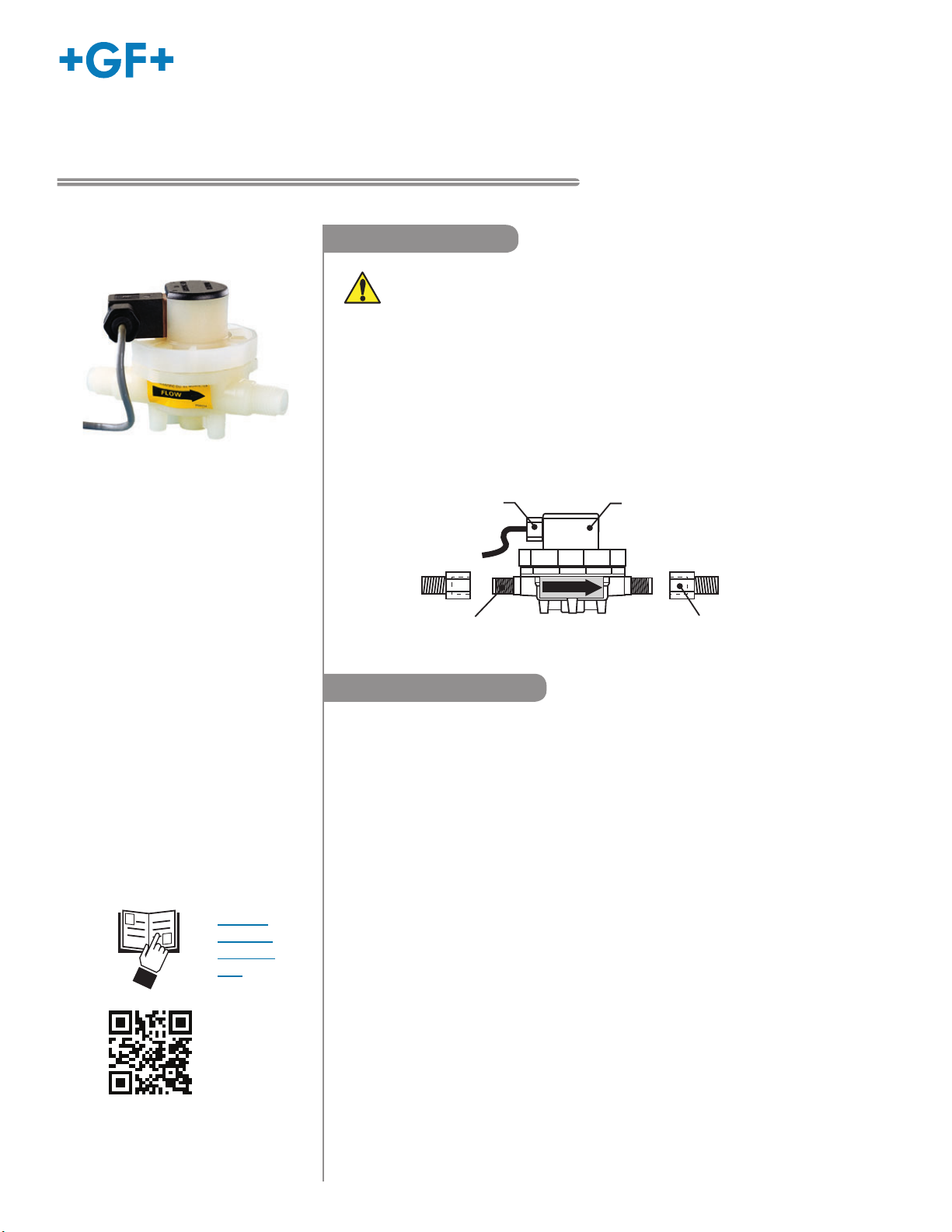
The Signet 2507 Mini Flow Sensor contains a free-running rotor which is driven by
the fl uid fl ow. Within the given measurement range, the rotational speed of the rotor
is proportional to the fl uid fl ow rate. Permanent magnets built into the rotor actuate
an electronic switch in the top of the sensor generating a square-wave output signal
proportional to fl ow rate. Both opaque and transparent fl uids can be measured from
0.2 to 20.0 centistokes.
Wetted sensor parts are constructed of PVDF and FKM, making the sensor suitable for
use with most process fl uids, including most acids, bases, light oils, and solvents.
English
Operating Instructions
WARNING! Polar organic solvents (i.e., ketones and chlorinated hydrocarbons)
and aromatic hydrocarbons are not compatible with this sensor.
able plug
25 ft cable
1
G
/4 in.
port threads
FLOW
Lower body with
built-in rotor
Upper body with
electronic switch
Pipe fitting adapter
1
G
/4 x 1/4 in. NPT
(2 included)
Ordering Information
Mini Flow low fl ow sensor with free-running rotor
Mfr. Part No. Code Insert Option
3-2507.100-1V 198 801 731 With 1 mm insert; for 100 to 2000 mL/m
(0.026 to 0.528 gpm) (available in Europe only)
3-2507.100-2V 198 801 732 With 2 mm insert; for 0.15 to 0.740 gpm
(400 to 2800 mL/m)
3-2507.100-3V 198 801 733 With 3 mm insert, for 0.185 to 1.123 gpm
(700 to 4200 mL/m)
3-2507.100-4V 198 801 734 With 4 mm insert, for 0.343 to 1.585 gpm
• English
• Deutsch
• Français
• 中文
3-2507.100-6V 198 801 736 With 6 mm inlet, no insert, for 0.845 to 3.170 gpm
Accessories and Replacement Parts
Mfr. Part No. Code Description
3-2507.080-2 198 801 550 Rotor, 2507
3-2507.080-3 198 801 547 Quad ring, 2507
3-2507.080-5 198 801 508 DIN connector, 2507
3-2507.081-2 198 801 502 2 mm insert
3-2507.081-3 198 801 503 3 mm insert
3-2507.081-4 198 801 558 4 mm insert
5523-0222 159 000 392 Cable (per foot), 2 cond. w/shield, 22 AWG
(1300 to 6000 mL/m)
(3200 to 12000 mL/m)
Page 2
Warranty Information
Specifi cations
Refer to your local Georg Fischer Sales offi ce for the most
current warranty statement.
All warranty and non-warranty repairs being returned must
include a fully completed Service Form and goods must be
returned to your local GF Sales offi ce or distributor.
Product returned without a Service Form may not be
warranty replaced or repaired.
Signet products with limited shelf-life (e.g. pH, ORP, chlorine
electrodes, calibration solutions; e.g. pH buffers, turbidity
standards or other solutions) are warranted out of box but not
warranted against any damage, due to process or application
failures (e.g. high temperature,
mishandling (e.g. broken glass,
chemical poisoning, dry-out) or
damaged membrane, freezing
and/or extreme temperatures).
Product Registration
Thank you for purchasing the Signet line of Georg Fischer
measurement products.
If you would like to register your product(s), you can now
register online in one of the following ways:
• Visit our website www.gfsignet.com.
Under Service and Support click on
Product Registration Form
• If this is a pdf manual (digital copy),
click here
Safety Information
General
Compatibility ...................... Signet 8550 Flow Transmitter
Signet 8900 Multi-Parameter
Controller
Signet 9900 Transmitter
Operating Range
-1V sensor...................... 100 to 2000 mL/m
(0.026 to 0.528 U.S. gpm)
(available in Europe only)
-2V sensor...................... 400 to 2800 mL/m
(0.105 to 0.740 U.S. gpm)
-3V sensor...................... 700 to 4200 mL/m
(0.185 to 1.123 U.S. gpm)
-4V sensor...................... 1300 to 6000 mL/m
(0.343 to 1.585 U.S. gpm)
-6V sensor...................... 3200 to 12000 mL/m
(0.845 to 3.170 U.S. gpm)
Accuracy ............................±2% of reading
Repeatability ......................±0.25% of full range
Viscosity range ..................0.2 to 20.0 centistokes
Pipe connections ............... G 1/4 in. ports, 1/4 in. NPT (male)
pipe adapters (2 included)
Wetted Materials
Housing ..........................PVDF
Flow insert......................PTFE
Quad ring seal................FKM
Rotor ..............................PVDF
Pipe thread adapters......PVDF
Suitable for clean fl uids only
1. Do not remove from pressurized lines.
2. Confi rm chemical compatibility before use.
3. Do not exceed maximum temperature/pressure
specifi cations.
4. Wear safety goggles or faceshield during
installation/service.
5. Do not alter product construction.
6. Failure to follow safety instructions could result in severe
personal injury.
Caution / Warning / Danger
Indicates a potential hazard. Failure to follow all warnings
may lead to equipment damage, injury, or death
Electrostatic Discharge (ESD) / Electrocution Danger
Alerts user to risk of potential damage to product by ESD,
and/or risk of potential of injury or death via electrocution.
Personal Protective Equipment (PPE)
Always utilize the most appropriate PPE during
installation and service of Signet products.
Pressurized System Warning
Sensor may be under pressure, take caution to vent
system prior to installation or removal. Failure to do so
may result in equipment damage and/or serious injury.
Hand Tighten Only
Overtightening may permanently damage product threads
and lead to failure of the retaining nut.
Do Not Use Tools
Use of tool(s) may damage product beyond repair and
potentially void product warranty.
Electrical
Power ................................ 5 to 24 VDC ±10%, regulated,1
0 mA max.
Output Type ....................... Open-collector, sinking,
10 mA max.
Cable Length ..................... 7.6m (25 ft), can be extended up to
300 m (1000 ft)
Cable type ......................... 2-conductor shielded, twisted-pair,
22 AWG
Max. Temperature/Pressure Rating
5.5 bar @ -18 °C (80 psi @ 0 °F)
5.5 bar @ 24 °C (80 psi @ 75 °F)
3 bar @ 120 °C (45 psi @ 248 °F)
Shipping Weight
0.115 kg (0.25 lb)
Standards and Approvals
CE
Manufactured under ISO 9001 for Quality, ISO 14001
for Environmental Management and OHSAS 18001 for
Occupational Health and Safety.
China RoHS (Go to www.gfsignet.com for details)
This device complies with Part 15 of the FCC rules Operation
is subject to the following two conditions:
(1) This device may not cause harmful interference, and,
(2) This device must accept any interference received,
including interference that may cause undesired operation
.
2
Signet 2507 Mini Flow Sensor
Page 3
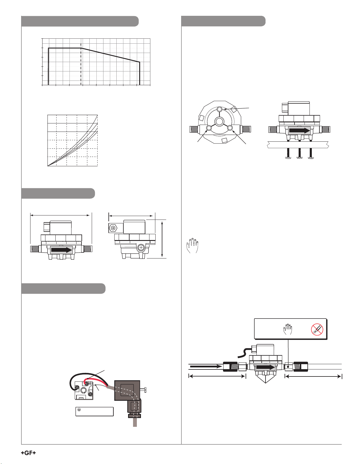
psibar
6.9 100
5.5 80
4.1 60
2.8 40
1.4 20
0
-40
0 40 80 120 160 200 240 280
°F
02040607080
0.25
0.50
0.75
1.00
1.25
1.50
3.63
7.25
10.88
14.50
18.13
21.76
PSI
BAR
Flow rate (%) of full scale
-2V
-3V
-4V
-6V
1
2
Sensor
Ground
(silver wire)
Sensor Power:
5 to 24 VDC
(black wire)
Sensor Signal Output
(Red wire)
Max cable length:
305 m (1000 ft)
Sensor
Plug (side)
Disregard ground
symbol on connector
Temperature/PressureGraphs
Pressure Drop Across Sensor vs. Flow Rate
Dimensions
95 mm (3.74 in.)
68 mm (2.7 in.)
Installation
• The sensor may be installed in any position,although
horizontal fl ow is recommended (the sensor mounted
upright). If the sensor is not installed upright, the linearity
error may be greater in the lower part of the sensor's
measurement range.
• Mounting tabs are provided using M4 or #8 self-tapping
screws (customer supplied).
Mounting Tab Hole Pattern
FLOW
• Install sensor with the arrow pointing in the direction of fl ow.
• Always maximize distance between the sensor and pump
source. Never install immediately downstream of valves,
fi ttings, etc. For optimum performance, a straight fl ow run of
at least 100 mm to 150 mm (4 in. to 6 in.) should be provided
before and after the sensor.
Wiring
Cable Extensions
• 2507 fl owmeters distributed in the U.S. include
7.6 m (25 ft) of cable.
• The cable can be extended to 300 m (1000 ft).
• Always maintain cable shield through cable splice.
• 2507 fl owmeters distributed in Europe do not include cable.
Refer to the sensor plug connection diagram for connection
details. (Below)
Sensor Plug Connection Diagram
FLOW
• Two pipe fi tting adapters (included) convert the G 1/4 in.
straight threads to 1/4 in. NPT pipe threads.
65 mm
(2.6 in.)
Hand tighten only! Apply 1-2 turns of PTFE sealing tape to
all threaded connections to prevent leaks.
Installation Tips
• Avoid vibrations and shocks.
• Avoid solids in the fl uid.
• Install a fi lter or line strainer upstream to protect sensor.
Pipe Fitting
Adapters
(included)
FLOW
FLOW
100 mm to 150 mm
(4 in. to 6 in.)
Mounting
tabs (3)
Signet 2507 Mini Flow Sensor
Hand
tighten
only!
Coupling
Pipe or
tubing
100 mm to 150 mm
(4 in. to 6 in.)
3
Page 4
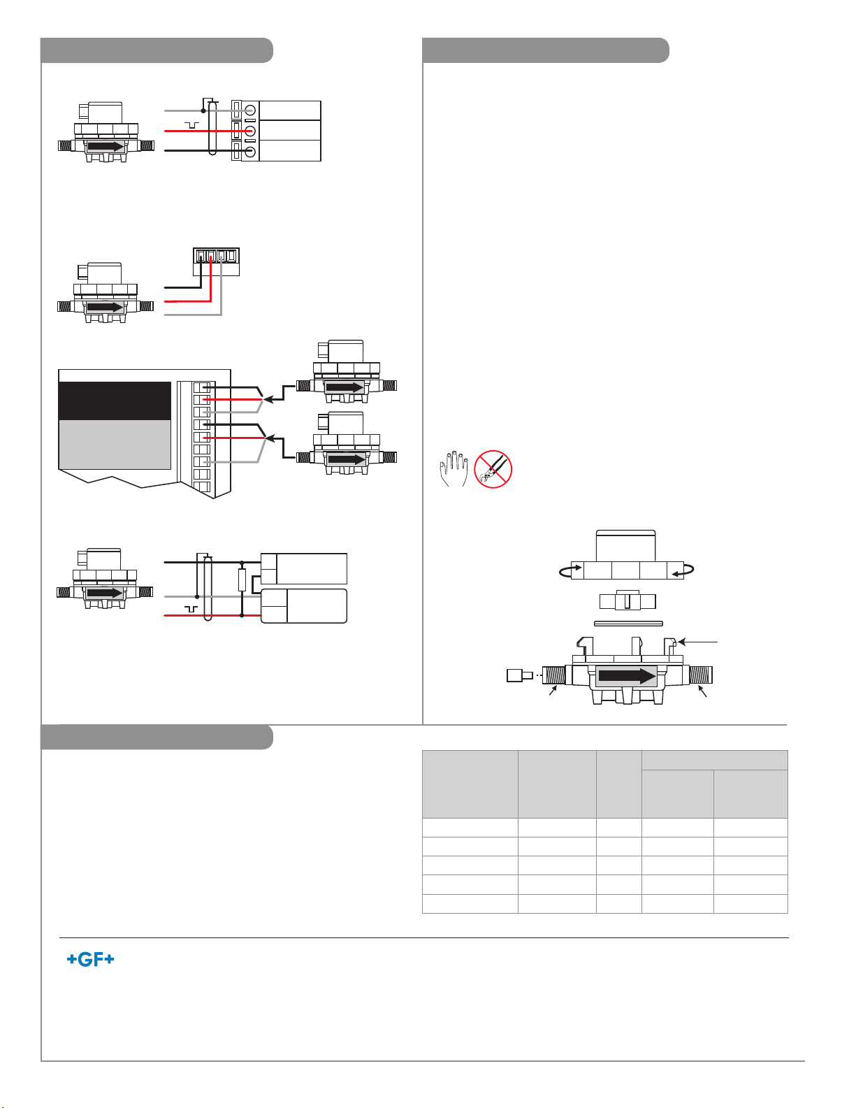
Instrument Connections
Replacing The Flow Insert
2507
FLOW
2507
FLOW
Signet 8900
I/O Module 3-8900.401-X
Frequency
Frequency
Input 2
Input
Freq. Input (Red)
1
Freq. Input 2 (Red)
OR
S3L
Input
2
GND (White/Shield)
+5VDC (Black)
GND (Shield)
+5VDC (Black)
3
S L (Red)
+5VDC (Black)
Shield
Red
Black
Signet 9900
Frequency
V+
Black
Red
Shield
3-8900.621C
1
2
3
4
5
6
7
8
9
SHLD
DATA
GND
No connection
Black
Red
Shield
Black
Red
Shield
Signet 8550
Sensr Gnd
9
(SHIELD)
Sensr IN
8
(RED)
Sensr V+
7
(BLACK)
2507
FLOW
2507
FLOW
Sensor range can be modifi ed by changing the fl ow insert.
The sensor must be removed from service and disassembled
prior to installing the new fl ow insert. See Specifi cations
(Section 2) for fl ow range data.
Flow Insert Replacement Procedure:
1. Depressurize system and remove sensor.
2. Rotate the upper sensor body clockwise until it releases
from the lower half, then lift off.
3. Remove rotor and quad ring seal from lower body.
4. Push the fl ow insert outward using a small screwdriver.
5. Install the new fl ow insert (small diameter inward) with
the eraser end of a pencil. Apply light pressure until insert
seats against the step in the lower body. Do not force!
6. Install rotor into lower body. Spin rotor with fi nger and
check for free rotation. If rotor hits fl ow insert, remove
rotor and push insert back until free rotor rotation is
established. Use a rounded object like a pen or pencil
body to adjust fl ow insert depth.
7. Install rotor, quad ring, and upper body. Hand tighten
only! Do not overtighten upper body or the lower body
assembly tabs will break.
8. Reprogram instrument with new K-Factor,
see Calibration..
WARNING!
Do not use tools of any kind on the sensor body
or port connections. Hand tighten only! Excessive
force will damage sensor.
2507
FLOW
• Pull-up resistor required (10 kΩ recommended). Consult your instrument
manual for additional information.
Black
Shield
Red
10k Ω
+
-
Gnd.
Input
5 to 24
VDC
Other
instrument
Other
Brands
Calibration
The K-Factors listed here represent the number of pulses the
sensor will generate for each measured engineering unit. They
are listed in Liters and in U.S. gallons for each sensor model.
IMPORTANT!
• K-Factors must be considered as approximate values.
• The number of pulses per volumetric unit may vary
depending on the medium and the installation.
• For optimum performance, the system must be calibrated
after installation.
External Power supply
Upper body
Assemble
(counterclockwise)
flow
insert
Inlet port
FLOW
Lower Body
Rotor
Quad ring seal
Outlet port
Disassemble
(clockwise)
Assembly
Tabs (3)
K-FACTORS
Sensor
Model
Code
Flow
Insert
Pulses per
LITER
Pulses per
U.S.
Gallon
3-2507.100-1V 198 801 731 1 mm 3413 12918
3-2507.100-2V 198 801 732 2 mm 1687 6385
3-2507.100-3V 198 801 733 3 mm 1045 3955
3-2507.100-4V 198 801 734 4 mm 721 2729
3-2507.100-6V 198 801 736 NONE 382 1446
Georg Fischer Signet LLC, 3401 Aerojet Avenue, El Monte, CA 91731-2882 U.S.A. • Tel. (626) 571-2770 • Fax (626) 573-2057
For Worldwide Sales and Service, visit our website: www.gfsignet.com • Or call (in the U.S.): (800) 854-4090
For the most up-to date information, please refer to our website at www.gfsignet.com
3-2507.090 Rev 20 03/19 English © Georg Fischer Signet LLC 2019
 Loading...