

Page 1
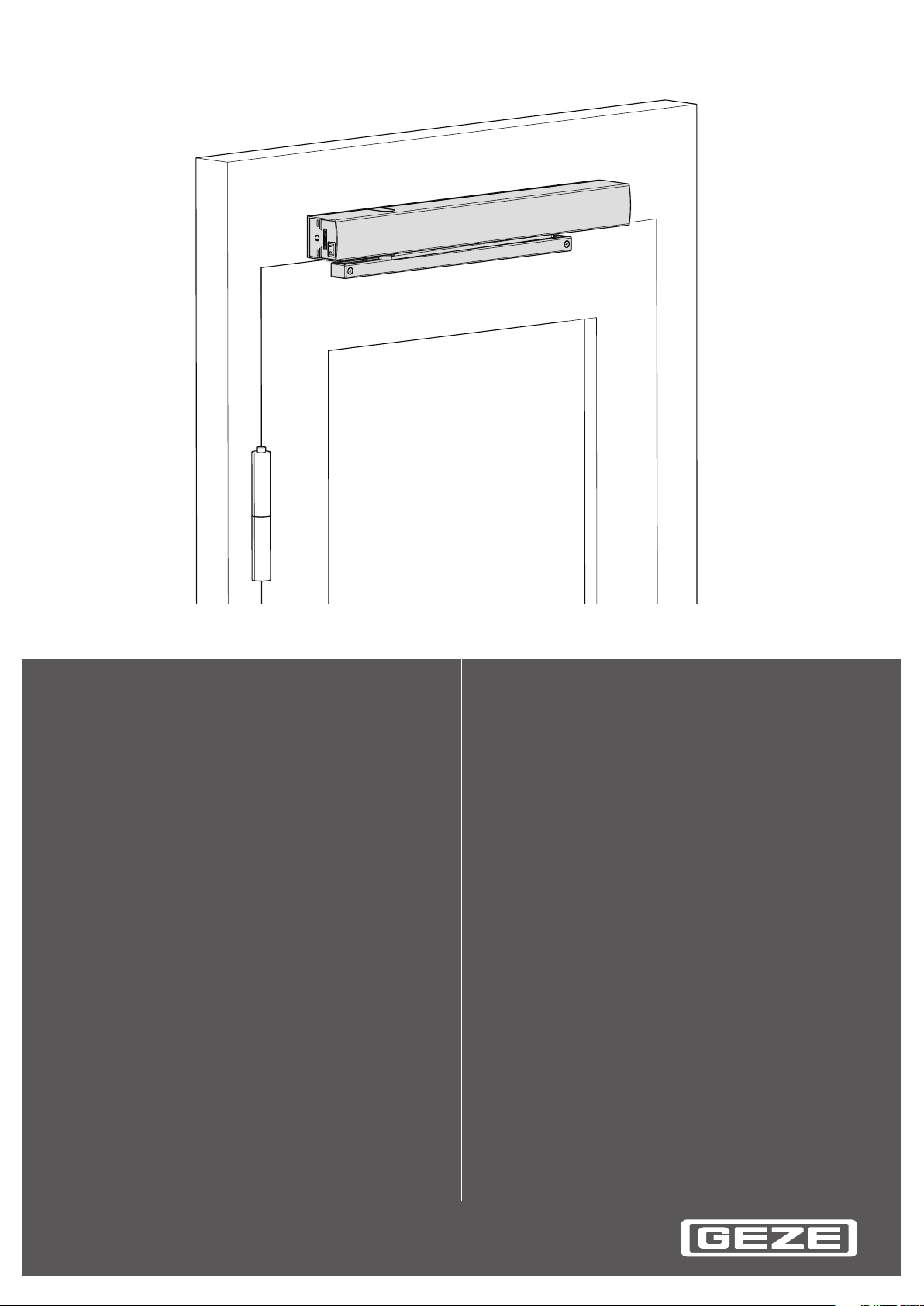
ECturn
Translation of the original instructions
GB User manual
1
Page 2

ECturn
2
Contents
1 Symbols and means of representation ............................................................................................................3
2 Product liability ........................................................................................................................................................3
3 Safety instructions ...................................................................................................................................................4
4 Terms ............................................................................................................................................................................5
5 Structure .....................................................................................................................................................................6
6 Operation ...................................................................................................................................................................7
6.1 Functions .............................................................................................................................................................................................................7
6.2 Operating modes .............................................................................................................................................................................................7
6.3 Button programme switch TPS (optional)...............................................................................................................................................8
7 What to do if ... ? .......................................................................................................................................................9
8 Cleaning and maintenance ............................................................................................................................... 10
9 Technical data .........................................................................................................................................................11
Page 3
ECturn
3
Symbols and means of representation
Symbols and means of representation1
Warnings
In these instructions, warnings are used to warn against material damage and injuries.
X
Always read and observe these warnings.
X
Observe all the measures that are marked with the warning symbol and warning word.
Warning
symbol
Other symbols and means of representation
Important information and technical notes are emphasised in order to illustrate the correct operation.
Symbol Meaning
X
Warning word Meaning
CAUTION
means "important note"
means "additional information"
Symbol for an action: Here you have to do something.
X
Observe the sequence if there are several action steps.
Danger for persons.
Non-compliance can result in minor injuries.
Product liability2
In accordance with the liability of the manufacturer for his products as dened in the German "Produkthaftungsgesetz" (Product Liability Act), the information contained in this brochure (product information and proper use,
misuse, product performance, product maintenance, obligations to provide information and instructions) is to be
observed. Non-compliance releases the manufacturer from his statutory liability.
Page 4

ECturn
4
Safety instructions
Safety instructions3
Thoroughly read and abide by this user manual before commissioning the door. In addition, always observe the
following safety precautions:
The prescribed mounting, maintenance and repair work must be performed by properly trained personnel à
authorised by GEZE.
The country-specic laws and regulations are to be observed during safety-related tests. à
GEZE shall not be liable for injuries or damage resulting from unauthorised modication of the system. à
GEZE shall not be liable if products from other manufacturers are used with GEZE equipment. à
Only original GEZE parts may be used for repair and maintenance work as well. à
The connection to the power supply must be made by a professional electrician. Perform the power connec- à
tion and safety earth conductor test in accordance with DIN VDE 0100-610.
Exception: If the ECturn swing door drive is connected to the mains voltage by the mounted power plug, the
connection does not have to be carried out by a qualied electrician.
Use a customer-accessible 10-A automatic circuit-breaker as the line-side disconnecting device. à
Protect the programme switch against unauthorised access. à
If a battery is connected: à
Check the battery function once a month. à
Recycle defective batteries. à
If changes are carried out in the detection eld of the safety sensors (e.g. objects added or removed): Reteach à
the drive.
Observe the latest versions of guidelines, standards and country-specic regulations, in particular: à
BGR 232 "Guidelines for power-operated windows, doors and gates" à
DIN 18650 "Building hardware - Powered pedestrian doors" à
VDE 0100; Part 610 "Erection of low-voltage installations" à
Accident-prevention regulations, especially BGV A1 "General regulations" and BGV A2 "Electrical systems à
and equipment".
Page 5
ECturn
5
Ter ms
Terms4
Ter m Statement
Hinge side That side of the door at which the hinges from which the door leaf is suspended are located.
Usually that side of the door located in the opening direction.
Opposite hinge side That side of the door that lies opposite the hinge side. Usually that side of the door located in
the closing direction.
Contactor Button, switch or motion detector for actuating the door drive.
Actuation function in the "Automatic" operating mode.
The contactor does not have any function in the "Night"/"O" operating mode.
Contactor
authorised (KB)
Contactor with
switch function
Push & Go When the door is pressed manually out of the closing position during an activated Push & Go
Safety sensor open
(SIO)
Safety sensor close
(SIS)
Stop Self-locking switch with which immediate stopping of the door drive can be triggered in case
Electrical door
opener
Lock feedback The lock feedback function is a contact integrated in the door latch that is activated when the
Access control function (for example key-operated switch or card reader) used by authorised
persons to actuate the door drive.
The actuation function is active in the "Automatic" and "Night" operating modes.
Button for opening and closing the door. Actuation function only in the "Automatic" operating
mode. The door is opened automatically when the button is rst pressed and closed again automatically when the button is pressed the second time. The function can be activated during
commissioning by parameter conguration.
function in the "Automatic" operating mode, the door opens automatically as soon as a specic
adjustable opening angle is exceeded.
Presence detector (e.g. active infrared light sensor) for protecting the swinging range of the
door in the opening direction. As a rule the sensor is located on the hinge side of the door on
the door leaf.
Presence detector (for example active infrared light sensor) for protecting the swinging range
of the door in the closing direction. As a rule the sensor is located on the side opposite the
hinge on the door leaf.
of danger. The drive remains in its current position until the user releases the stop switch again,
thus terminating the stop situation.
Open-circuit door opener
Available as AC or DC door opener version. When the door drive is actuated, the door opener is
activated by the control unit of the door drive in as far as the door is in the closing position. The
door opener remains activated until the door has left the closing position.
Closed-circuit door opener
DC door opener version. The door opener is switched o when the door drive is activated, in as
far as the door is in the closing position. The door opener remains switched o until the door
has left the closing position.
door is locked mechanically by the tie bolt of the door lock. It signals to the control unit that the
door is locked mechanically and can therefore not be opened by the door drive. In this case the
control unit ignores the actuation commands of all the contactors.
Page 6
ECturn
6
Structure
Structure5
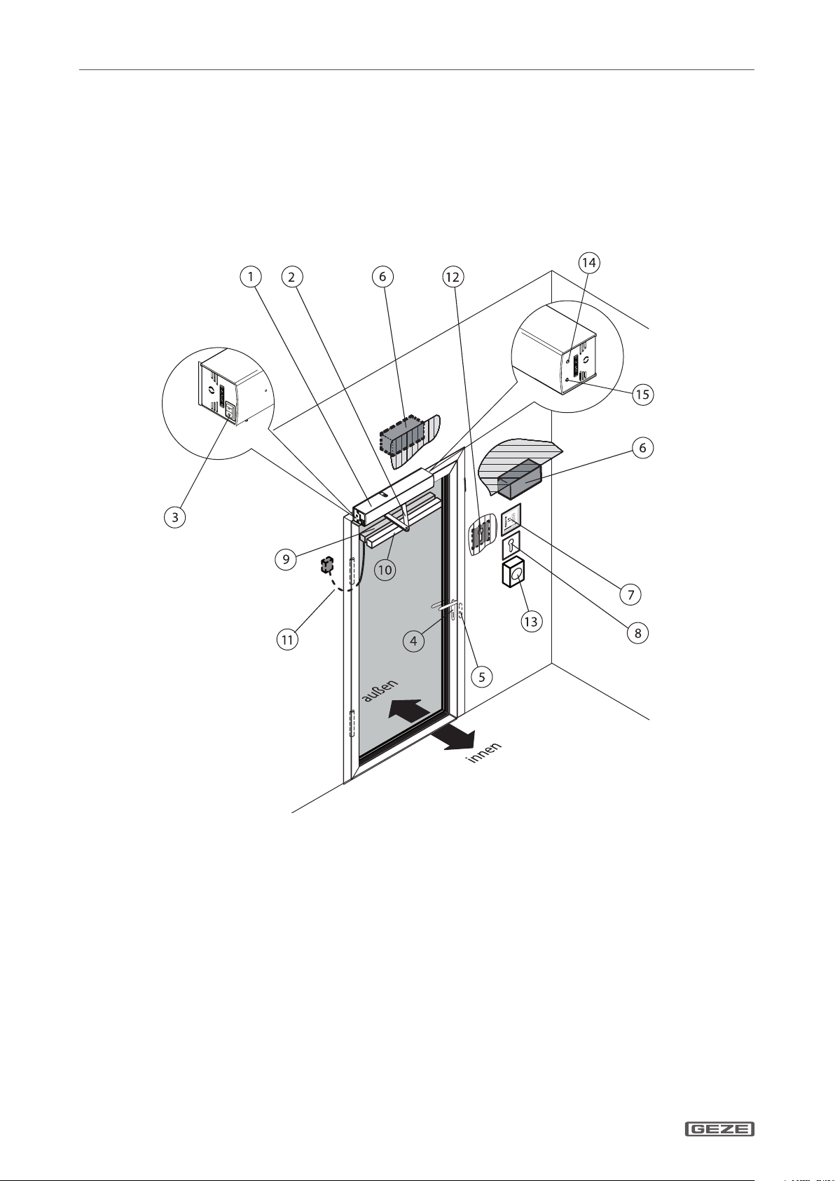
System parts and options
The door drive unit can be mounted in transom mounting at the lintel or in door panel mounting on the door à
panel.
The door drive is available as a 1-leaf version. à
The operating elements are arranged dierently depending on the situation. à
For technical reasons, we cannot show all of the possibilities here.
Door drive unit1
Link arm or guide rail2
Internal programme switch3
Door handle with door lock4
Electrical door opener5
Contactor6
Button programme switch7
Key-operated switch: Enabling of button pro-8
gramme switch
Safety sensor open (SIO)9
Safety sensor close (SIS)10
Door transition cable11
Contactor authorised (KB)12
Stop switch13
Operating modes switch14
Operating mode LED15
Page 7
ECturn
7
Operation
Operation6
Functions6.1
The set parameters of the drive functions may only be modied by properly trained persons.
Commissioning and the setting or modication of the door parameters as well as of some special drive functions
can be carried out by using the buttons S1, S2 and the 5 LEDs on the controller or with the display programme
switch (see wiring diagram ECturn, ID No. 134079).
Normal operation6.1.1
In normal door operation, the door is opened and closed automatically.
Special cases
In specic cases (e.g. special wiring, special function settings/parameters, special software) deviations from the
information given in this user manual may occur.
X
If this is the case, please ask the responsible service technician.
Functions in normal operation Result
A contactor (button, switch or motion detector)
is triggered.
Safety sensor close (SIS) is is triggered when the door is
open (e.g. light sensor).
Safety sensor close (SIS) is triggered while the door is
closing.
Safety sensor open (SIO) is triggered while door is open-
ing.
Safety sensor open (SIO) is triggered when the door is
closed.
A person moves toward the opened door and a motion
detector is activated.
A person moves toward the closing door and a motion
detector is activated.
Door contacts an obstruction when opening. Door stops, waits and attempts again to move to the open
Door contacts an obstruction when closing. Door reopens immediately, waits the hold-open time and
Door opens, waits the hold-open time and then closes.
Door remains open.
Door reopens immediately.
The door stops and remains in the position until the end
of actuation (door opens) or until the end of the holdopen time (door closes).
Door remains closed.
Door remains open.
Door reopens immediately.
position at a reduced speed. The door then closes again.
then closes at a reduced speed.
Switch/button Function
Stop switch The door stops immediately (in every operating mode)
and holds the position until the stop switch is unlocked.
Contactor authorised (KB, e.g. outside key-operated
switch)
Door opens once and closes after the hold-open time. The
set operating mode is retained.
Battery operation in case of power failure6.1. 2
If a battery is installed, the swing door drive remains operational after a power failure for a period of up to 15
minutes (depending on the charging state of the battery and frequency with which the door is used).
For setting of the swing door drive with battery operation after a power failure refer to the ECturn wiring diagram (ID No. 134079).
Operating modes6.2
Operating mode Colour
Automatic Green
Night Red
Permanently open Blue
O No colour
Page 8
ECturn
8
Operation
Button programme switch TPS (optional)6.3
Can be connected additionally to the internal programme switch.
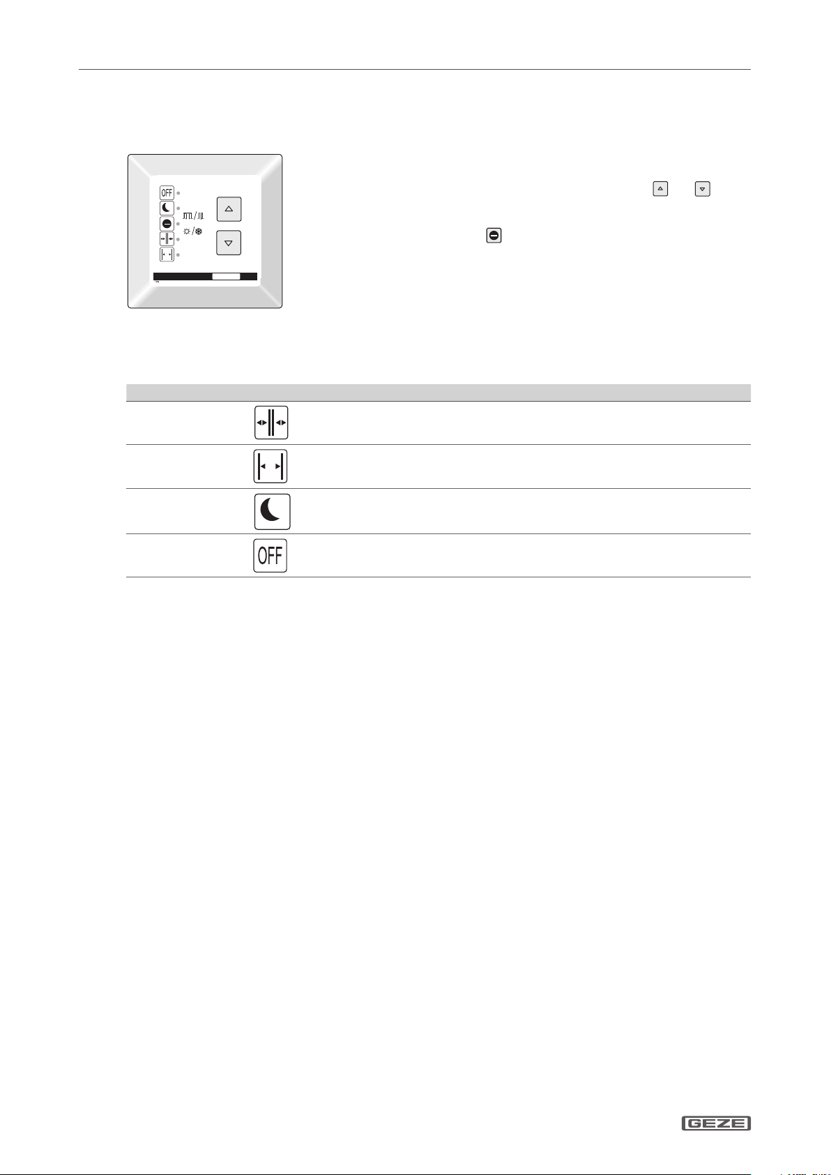
At the button programme switch, the system operating mode is selected and
the corresponding programme is displayed.
The desired operating mode can be selected by pressing the
tons.
The LED of the current operating state lights up.
The shop closing time switch
The button programme switch is accessible for everyone without a key-operated switch. If desired, an additional key-operated switch can be used for locking.
When using a key-operated switch: Enable by operating the key-operated
Button programme switch TPS
Operating mode Switches Description
Automatic
switch once briey.
Operation of the key programme switch is disabled by briey re-actuating the
key switch.
Door opens and closes automatically. The contactors are active.
and but-
is not assigned.
Permanently open
Night
On / O
Door remains open.
Door opens and closes only when actuated using the key-operated switch.
Door is enabled and can be moved by hand.
Page 9
ECturn
9
What to do if ... ?
What to do if ... ?7
Problem Cause Remedy
Door only opens and closes
slowly
Obstruction on the sliding
path
Safety sensor close (SIS)
soiled
Safety sensor close (SIS)
misaligned or defective
Door opens and closes
constantly
Obstruction on the sliding
path
Light beams or reections,
e.g. reective oor, falling
rain
Misaligned movement
detector
Door only opens a crack Obstruction on the sliding
path
Door does not open Obstruction on the sliding
path
Movement detector
misaligned or defective
(outside)
Stop activated Unlock the stop function.
"Night" operating mode Select a dierent operating mode.
Door locked mechanically Unlock the door.
Door opener does not
release
Drive defective Notify a service technician.
Door does not close Safety sensor close (SIS)
soiled
Safety sensor close (SIS)
misaligned or defective
Obstruction on the sliding
path
Movement detector controls
uninterruptedly
"Permanently open" operat-
ing mode
Current impulse button
function actuates
Operating mode LED ashes
Fault message Notify a service technician
red, green or blue
Operating mode LED ashes
yellow (2x fast)
Initialisation after power
failure
X
Remove obstruction and check door leaf for ease of movement.
X
Clean the Safety sensor close.
X
Notify a service technician.
X
Remove obstruction and check door leaf for ease of movement.
X
Check detection eld of movement detector
X
Check detection eld of movement detector
X
Remove obstruction and check door leaf for ease of movement.
X
Remove obstruction and check door leaf for ease of movement.
X
Check the movement detector. If necessary, notify a service
technician.
X
X
X
X
Notify a service technician.
X
X
Clean the Safety sensor close (SIS).
X
Notify a service technician.
X
Remove obstruction and check door leaf for ease of movement.
X
Check the movement detector. If necessary, notify a service
technician.
X
Select a dierent operating mode.
X
Terminate actuation by pressing the button once more.
X
X
Wait for initialisation drive.
Page 10
ECturn
10
Cleaning and maintenance
Cleaning and maintenance8
CAUTION!
Danger of injury due to impact and crushing!
X
The mounting, maintenance and repair work must be performed by properly trained personnel authorised by
GEZE.
X
Disconnect the drive from the power supply before carrying out work.
X
Unplug the battery plug from the controller before carrying out work.
X
Secure door leaves against accidental movement before carrying out work.
X
Ensure that the drive cannot be activated via radio or Contactor authorised (KB).
Cleaning
Component Cleaning
Safety sensor close (SIS, e.g. light sensors) Wipe with a moist cloth.
Glass surfaces Wipe with a cold vinegar/water mixture; then dry.
Stainless surfaces Wipe with a non-scratching cloth.
Painted surfaces Wipe with water and soap.
Anodised surfaces Wipe with non-alkaline potassium soap (pH value 5.5…7)
Maintenance
The owner must ensure that the system functions properly.
GEZE oers maintenance contracts with the following services:
Inspect fastening elements for rm seating à
Carry out miscellaneous adjustment work à
Carry out operational checks à
Check all the safety and control equipment of the door system à
Lubricate all the moveable parts à
X
If maintenance is required, notify the service technician.
X
X
X
X
X
Inspection by trained professionals
In accordance with the "Guidelines for power-operated windows, doors and gates" (BGR 232 and GUV 16.10) Section 6, power-operated doors must be inspected for safety by a trained professional before initial commissioning
and at least once a year.
Page 11
ECturn
11
Technical data
Technical data9
Opening speed 0 °/s … 45 °/s
Closing speed 0 °/s … 45 °/s
Electrical connection values 110 – 230 V; 50 – 60 Hz pursuant to DIN IEC 38
Connected load
Fuse protection Power supply connection 230 V, customer-accessible 10 A
Current draw for external devices 24 V DC connection; max. 600 mA
Temperature range –15 °C … +50 °C; for dry rooms only
Enclosure rating IP 20
We reserve the right to make changes.
max. 300 W
Rated voltage 230 W
Page 12

Germany
GEZE Sonderkonstruktionen GmbH
Planken 1
97944 Boxberg-Schweigern
Tel. +49 (0) 7930-9294-0
Fax +49 (0) 7930-9294-10
E-Mail: [email protected]
Germany
GEZE GmbH
Niederlassung Nord/Ost
Bühringstraße 8
13086 Berlin (Weissensee)
Tel. +49 (0) 30-47 89 90-0
Fax +49 (0) 30-47 89 90-17
E-Mail: [email protected]
Germany
GEZE GmbH
Niederlassung West
Nordsternstraße 65
45329 Essen
Tel. +49 (0) 201-83082-0
Fax +49 (0) 201-83082-20
E-Mail: [email protected]
Germany
GEZE GmbH
Niederlassung Mitte
Adenauerallee 2
61440 Oberursel (b. Frankfurt)
Tel. +49 (0) 6171-63610-0
Fax +49 (0) 6171-63610-1
E-Mail: [email protected]
Germany
GEZE GmbH
Niederlassung Süd
Reinhold-Vöster-Straße 21-29
71229 Leonberg
Tel. +49 (0) 7152-203-594
Fax +49 (0) 7152-203-438
E-Mail: [email protected]
Germany
GEZE Service GmbH
Reinhold-Vöster-Straße 25
71229 Leonberg
Tel. +49 (0) 7152-9233-0
Fax +49 (0) 7152-9233-60
E-Mail: [email protected]
Germany
GEZE Service GmbH
Niederlassung Berlin
Bühringstraße 8
13086 Berlin (Weissensee)
Tel. +49 (0) 30-470217-30
Fax +49 (0) 30-470217-33
E-Mail: [email protected]
Austria
GEZE Austria GmbH
Mayrwiesstraße 12
5300 Hallwang b. Salzburg
Tel. +43-(0)662-663142
Fax +43-(0)662-663142-15
E-Mail: [email protected]
Baltic States
GEZE GmbH Baltic States oce
Dzelzavas iela 120 S
1021 Riga
Tel. +371 (0) 67 89 60 35
Fax +371 (0) 67 89 60 36
E-Mail: o[email protected]
Benelux
GEZE Benelux B.V.
Leemkuil 1
Industrieterrein Kapelbeemd
5626 EA Eindhoven
Tel. +31-(0)40-26290-80
Fax +31-(0)40-26 290-85
E-Mail: [email protected]
Bulgaria
GEZE Bulgaria - Trade
Representative Oce
61 Pirinski Prohod, entrance „B“,
4th oor, oce 5,
1680 Soa
Tel. +359 (0) 24 70 43 73
Fax +359 (0) 24 70 62 62
E-Mail: o[email protected]
China
GEZE Industries (Tianjin) Co., Ltd.
Shuangchenzhong Road
Beichen Economic Development
Area (BEDA)
Tianjin 300400, P.R. China
Tel. +86(0)22-26973995-0
Fax +86(0)22-26972702
E-Mail: [email protected]
China
GEZE Industries (Tianjin) Co., Ltd.
Branch Oce Shanghai
Unit 25N, Cross Region Plaza
No. 899, Ling Ling Road,
XuHui District
200030 Shanghai, P.R. China
Tel. +86 (0)21-523 40 960
Fax +86 (0)21-644 72 007
E-Mail: [email protected]
China
GEZE Industries (Tianjin) Co., Ltd.
Branch Oce Guangzhou
Room 17C3
Everbright Bank Building, No.689
Tian He Bei Road
510630 Guangzhou, P.R. China
Tel. +86(0)20-38731842
Fax +86(0)20-38731834
E-Mail: [email protected]
China
GEZE Industries (Tianjin) Co., Ltd.
Branch Oce Beijing
Rm3A02, Building 3,
ZhuBang 2000 Business Plaza,
No. 98, Balizhuang xili,
Chaoyang District,
100025 Beijing, P.R.China
Tel. +86-(0)10-8797 5177/-78
Fax +86-(0)10-8797 5171
E-Mail: [email protected]
France
GEZE France S.A.R.L.
ZAC de l’Orme Rond
RN 19
77170 Servon
Tel. +33-(0)1-606260-70
Fax +33-(0)1-606260-71
E-Mail: [email protected]
Hungary
GEZE Hungary Kft.
Bartók Béla út 105-113.
Budapest
H-1115
Tel. +36 (1) 481 4670
Fax +36 (1) 481 4671
E-Mail: o[email protected]
Iberia
GEZE Iberia S.R.L.
Pol. Ind. El Pla
C/Comerc, 2-22, Nave 12
08980 Sant Feliu de Llobregat
(Barcelona)
Tel. +34(0)9-02194036
Fax +34(0)9-02194035
E-Mail: [email protected]
India
GEZE India Private Ltd.
MF2 & 3, Guindy Industrial Estate
Ekkattuthangal
Chennai - 600 097
Tamilnadu
Tel. +91 (0) 44 30 61 69 00
Fax +91 (0) 44 30 61 69 01
E-Mail: o[email protected]
Italy
GEZE Italia Srl
Via Giotto, 4
20040 Cambiago (MI)
Tel. +3902950695-11
Fax +3902950695-33
E-Mail: [email protected]
Italy
GEZE Engineering Roma Srl
Via Lucrezia Romana, 91
00178 Roma
Tel. +3906-7265311
Fax +3906-72653136
E-Mail: [email protected]
Kazakhstan
GEZE Central Asia
050061, Almaty, Kasakhstan
Rayimbek ave. 348, A, oce 310
Tel. +7 (0) 72 72 44 78 03
Fax +7 (0) 72 72 44 78 03
E-Mail: o[email protected]
Poland
GEZE Polska Sp.z o.o.
ul. Annopol 21
03-236 Warszawa
Tel. +48 (0)22 440 4 440
Fax +48 (0)22 440 4 400
E-Mail: [email protected]
Romania
GEZE Romania S.R.L.
IRIDE Business Park
Building nr. 10, level 2
Str. Dimitrie Pompei nr. 9–9a
RO-020335 Bucharest, sector 2
Tel. +40 (0) 316 201 257
Fax +40 (0) 316 201 258
E-Mail: o[email protected]
Russian Federation
GEZE GmbH Representative
Oce Russia
Kolodesnij pereulok3, str. 25
Oce Nr. 5201-5203
107076 Moskau
Tel. +7 (0) 49 55 89 90 52
Fax +7 (0) 49 55 89 90 51
E-Mail: o[email protected]
Scandinavia
GEZE Scandinavia AB
Mallslingan 10
Box 7060
18711 Täby, Sweden
Tel. +46(0)8-7323-400
Fax +46(0)8-7323-499
E-Mail: [email protected]
Scandinavia
GEZE Norway
Industriveien 34 B
2072 Dal
Tel. +47(0)639-57200
Fax +47(0)639-57173
E-Mail: [email protected]
Scandinavia
GEZE Finland
Postbox 20
15871 Hollola
Tel. +358(0)10-4005100
Fax +358(0)10-4005120
E-Mail: [email protected]
Scandinavia
GEZE Denmark
Høje Taastrup Boulevard 53
2630 Taastrup
Tel. +45(0)46-323324
Fax +45(0)46-323326
E-Mail: [email protected]
South Africa
DCLSA Distributors (Pty.) Ltd.
118 Richards Drive, Midrand,
Halfway House Ext. 111
P.O. Box 7934
Midrand 1685
Tel. +27(0)113158286
Fax +27(0)113158261
E-Mail: [email protected]
Switzerland
GEZE Schweiz AG
Bodenackerstrasse 79
4657 Dulliken
Tel. +41-(0)62-2855400
Fax +41-(0)62-2855401
E-Mail: [email protected]
Turkey
GEZE GmbH Türkiye - İstanbul
İrtibat Bürosu
Ataşehir Bulvarı, Ata 2/3
Plaza Kat: 9 D: 84 Ataşehir
Kadıköy / İstanbul
Tel. + 90 (0) 21 64 55 43 15
Fax + 90 (0) 21 64 55 82 15
E-Mail: o[email protected]
Ukraine
Repräsentanz GEZE GmbH Ukraine
ul. Vikentiya Hvoyki, 21,
oce 151
04080 Kiev
Tel. +38 (0) 44 49 97 725
Fax +38 (0) 44 49 97 725
E-Mail: o[email protected]
United Arab Emirates/GCC
GEZE Middle East
P.O. Box 17903
Jebel Ali Free Zone
Dubai
Tel. +971(0)4-8833112
Fax +971(0)4-8833240
E-Mail: [email protected]
United Kingdom
GEZE UK Ltd.
Blenheim Way
Fradley Park
Licheld
Staordshire WS13 8SY
Tel. +44(0)1543443000
Fax +44(0)1543443001
E-Mail: [email protected]
GEZE GmbH
P.O.Box 1363
Reinhold-Vöster-Straße 21–29
71229 Leonberg
Germany
Tel.: 0049 7152 203-0
Fax.: 0049 7152 203-310
www.geze.com
135 86 3- 01
 Loading...