


Uninterruptible
Power
Supply
ON LINE MULTISTANDARD
3300 VA - 4000 VA
Manuale d’uso - User’s Manual - Bedienungsanleitung
Manuel d’utilisateur - Manual de Usuario


SICUREZZA 5
I
MANUALE D’USO 15
SAFETY 6
GB
USER’S MANUAL 41
SICHERHEIT 7
D
BEDIENUNGSANLEITUNG 67
SÉCURITÉ 8
F
MANUEL D’UTILISATEUR 93
SEGURIDAD 9
E
MANUAL DE USUARIO 119
GR ΑΣΦΑΛΕΙΑ 10
S SÄKERHETEN 11
NL VEILIGHEID 12
P SEGURANÇA 13
3

4

I SICUREZZA I
Questa parte del manuale contiene precauzioni da seguire scrupolosamente in quanto
riguardano la SICUREZZA.
a) L’UPS NON DEVE FUNZIONARE SENZA COLLEGAMENTO DI TERRA. Non togliere la spina
dalla rete di alimentazione perché verrebbe a mancare la terra di sicurezza per l’UPS e le
apparecchiature alimentate.
b) Evitare di collegare il neutro di uscita a quello di ingresso o a terra perché questa operazione
potrebbe causare malfunzionamenti.
c) L'UPS genera al suo interno delle tensioni elettriche PERICOLOSE. Tutte le operazioni di
manutenzione devono essere eseguite ESCLUSIVAMENTE da personale qualificato.
d) L'UPS contiene al suo interno una sorgente di energia: le batterie. Le prese d’uscita possono essere
in tensione anche senza connettere l'UPS alla rete.
e) La tensione totale di batteria può generare uno shock elettrico. Le batterie sostituite vanno
considerate RIFIUTO TOSSICO e trattate di conseguenza. Non gettare il pacco batterie sul fuoco:
possono esplodere. Non tentare di aprire il pacco batterie: sono prive di manutenzione. Inoltre
l'elettrolita è pericoloso per la pelle e per gli occhi e può risultare tossico.
f) Non accendere l'UPS se si nota una perdita di liquido, o se si vede una polvere bianca residua.
g) Evitare che acqua, liquidi in genere e/o altri oggetti estranei entrino nell'UPS.
h) Il cavo di alimentazione separabile è inteso come dispositivo di sezionamento. Aver cura di lasciar
libero uno spazio adeguato sul retro dell’UPS in prossimità del collegamento del cavo per un facile
scollegamento.
i) In condizioni di pericolo spegnere l’UPS con l’interruttore posto sul pannello frontale e togliere il
collegamento d’ingresso.
j) L' UPS genera una corrente di dispersione di circa 1 mA. Per garantire il limite massimo della
corrente di dispersione di 3.5 mA assicurarsi che il carico abbia una corrente di dispersione massima
di 2.5 mA. Se la corrente di dispersione del carico dovesse superare tale limite fare eseguire da
personale qualificato un collegamento dell' UPS alla rete di alimentazione di tipo industriale,
conforme IEC 309, dimensionato per una corrente adeguata alla taglia del gruppo.
k) Per l’espansione di batteria usare esclusivamente connettori forniti o autorizzati dalla ditta.
l) Gli UPS di questa serie sono stati realizzati per l’uso professionale e quindi non sono adatti per l’uso
in ambiente domestico.
m) Rispettando le indicazioni di neutro (N) e fase (F) relative a spine e
prese, l’UPS inserito in un impianto non modifica il regime di
neutro preesistente. La resistenza sul collegamento di neutro risulta
inferiore a 0,1Ω. Il regime di neutro viene comunque modificato se
è presente un trasformatore di isolamento o quando l’UPS funziona
con neutro sezionato a monte.
A lato è possibile vedere l’esatta posizione del pin di neutro nelle
varie prese e spine dell’UPS.
N
N
N
N
N
5

GB SAFETY GB
This part of the manual contains precautions that must absolutely be followed as they
relate to SAFETY.
a) The UPS MUST NOT BE OPERATED WITHOUT A GROUND CONNECTION. Do not pull out
the plug from the mains socket as this would remove the safety earth for the UPS and for the
equipment it is powering.
b) Avoid connecting the outlet neutral line to the input neutral or to the earth as this could cause
malfunctions.
c) The UPS internally generates DANGEROUS electrical voltages. All maintenance operations must be
carried out SOLELY by qualified operators.
d) The UPS contains a power source inside: the batteries. There may be live voltage on the output
sockets even without connecting the UPS to the mains.
e) The total battery voltage may generate an electric shock. All batteries substituted must be considered
as TOXIC WASTE and treated accordingly. Do not throw the battery pack into a fire: it could
explode. Do not try to open the battery pack - these batteries are maintenance-free. In addition the
electrolyte is dangerous to the skin and eyes and may be toxic.
f) Do not turn on the UPS if a liquid is seen to be leaking, or if a white powder residue can be seen.
g) Prevent water, liquids in general and/or other foreign matter from entering the UPS.
h) The detachable power cord can be considered to be a sectioning device. Make sure to leave enough
free space at the rear of the UPS in the vicinity of the cable connection point for easy disconnection.
i) In the presence of a hazard, switch off the UPS by the switch on the front panel and remove the input
connection.
j) The UPS gives rise to a dispersion current of about 1 mA. To guarantee the maximum limit
dispersion current of 3.5 mA, make sure that the maximum dispersion current of the load is 2.5 mA.
Where the dispersion current of the load is in excess of this limit, have qualified personnel connect
the UPS to an IEC 309 standard, industry type power supply mains, which will be sized for a current
suitable for the UPS’s power rating.
k) For battery expansions, use only connectors supplied or authorized by the manufacturer.
l) The UPS in this range are designed for professional use and are therefore not suitable for use in the
home.
m) Provided that the neutral (N) and phase (F) indications for plugs
and sockets are respected, the UPS does not alter the existing
neutral arrangements when inserted in an installation. The
resistance of the neutral connection is less than 0.1Ω. The neutral
arrangements are however altered if there is an isolating
transformer or when the UPS works with the neutral sectioned
upstream.
The figure to the side indicates the exact position of the neutral pin
of the various plugs and sockets of the UPS.
N
N
N
N
N
6

D SICHERHEIT D
Dieser Teil des Handbuchs enthält sorgfältig zu befolgende Vorsichtsmassnahmen, da
sie sich auf die SICHERHEIT beziehen.
a) DIE USV DARF NICHT OHNE ERDUNG FUNKTIONIEREN. Nicht den Stecker vom
Versorgungsnetz abziehen, da ansonsten die Schutzerdung für die USV und die versorgten Geräte
fehlen würde.
b) Es ist zu vermeiden, den Ausgangsnulleiter an den Eingangs- oder Erdnulleiter anzuschliessen, da
dieser Vorgang Betriebsstörungen verursachen könnte.
c) Die USV erzeugt in ihrem Innern GEFÄHRLICHE elektrische Spannungen. Alle Wartungsarbeiten
sind AUSSCHLIESSLICH durch qualifiziertes Personal auszuführen.
d) Die USV enthält in ihrem Innern eine Energiequelle, d.h. die Batterien. Die Ausgangssteckdosen
können unter Spannung stehen, auch ohne dass die USV ans Netz angeschlossen ist.
e) Die Batteriegesamtspannung kann einen Elektroschock erzeugen. Die ersetzten Batterien sind als
GIFTIGEN ABFALL zu betrachten und dementsprechend zu behandeln. Die Batterieblöcke nicht
ins Feuer werfen, denn sie können explodieren Nicht versuchen, den Batterieblock zu öffnen; sie
sind wartungsfrei. Ferner ist der Elektrolyt gefährlich für die Haut sowie für die Augen und kann
sich als giftig herausstellen.
f) Die USV nicht einschalten, wenn ein Flüssigkeitsverlust oder ein weisser Staubrückstand festgestellt
werden.
g) Es ist zu vermeiden, dass Wasser und Flüssigkeiten im allgemeinen und/oder andere fremde
Gegenstände in die USV eintreten.
h) Das trennbare Versorgungskabel ist als Trennvorrichtung zu verstehen. Es ist zu beachten, dass ein
angemessener Freiraum auf der Rückseite der USV in der Nähe des Kabelanschlusses zur leichten
Trennung gelassen wird.
i) In gefahrdrohenden Situationen die USV mit Hilfe des auf der Frontplatte angebrachten Schalters
ausschalten und die Eingangsverbindung abtrennen.
j) Die USV erzeugt einen Leckstrom von zirka 1 mA. Um die Höchstgrenze des Leckstroms von 3,5
mA zu gewährleisten, sich vergewissern, dass die Last einen maximalen Leckstrom 2,5 mA hat.
Falls der Leckstrom der Last diese Grenze übersteigen sollte, die USV durch qualifiziertes Personal
an ein industrielles, dem IEC 309 entsprechendes Versorgungsnetz anschliessen lassen, das für einen
der Grösse des USV Systems angemessenen Strom bemessen ist.
k) Für die Batterieerweiterung ausschliesslich durch die Firma autorisierte oder gelieferte Stecker
benutzen.
l) Die USV aus dieser Serie sind für den professionellen Gebrauch hergestellt und daher nicht für die
Benutzung im Haushalt geeignet.
m) Unter Beachtung der Nulleiter- (N) und Phasenangaben (F) über
die Stecker und Steckdosen, ändert die in eine Anlage eingefügte
USV nicht den zuvor bestehenden Nulleiterzustand ab. Der
Widerstand am Nulleiteranschluss ist kleiner als 0,1Ω. Der
Nulleiterzustand wird auf jeden Fall geändert, wenn ein
Trenntransformator vorhanden ist oder die USV mit einem vor der
USV getrennten Nulleiter funktioniert.
N
N
N
Auf der (rechten) Seite ist es möglich, die genaue Position des
Nulleiterpins in den verschiedenen Steckdosen und Steckern der
USV zu sehen.
N
N
7

F SÉCURITÉ F
Cette partie du Manuel concerne les mesures de SÉCURITÉ à suivre
scrupuleusement.
a) L’ASI NE DOIT PAS FONCTIONNER SANS RACCORDEMENT A LA TERRE. Ne pas
débrancher la fiche du réseau d’alimentation car l’ASI et les appareils qui y sont reliés ne seraient
plus raccordés à la terre du branchement électrique.
b) Eviter de brancher le neutre de sortie à celui d’entrée ou de terre car cette opération pourrait causer
des disfonctionnements.
c) L'ASI génère des tensions électriques DANGEREUSES. Toutes les opérations d’entretien doivent
être exécutées EXCLUSIVEMENT par un personnel qualifié.
d) L'ASI contient une source d’énergie: les batteries. Les prises de sortie peuvent être sous tension
même si l’ASI n’est pas branché au réseau.
e) La tension totale des batteries peut créer une décharge électrique. Les batteries remplacées doivent
être considérées comme des DECHETS TOXIQUES et éliminées en conséquence. Ne pas jeter le
pack batteries dans le feu: elles pourraient exploser. Ne pas essayer d’ouvrir le pack batteries: elles
ne nécessitent aucun entretien. En outre, l’électrolyte est dangereux pour la peau et pour les yeux, et
il peut s’avérer toxique.
f) Ne pas mettre l'ASI en marche en cas de perte de liquide ou en présence d’une poudre blanche
résiduelle.
g) Eviter que de l’eau, des liquides en général et/ou tout autre objet étranger ne pénètrent dans l'ASI.
h) Le câble d’alimentation séparable est considéré comme un dispositif de sectionnement. Laisser
toujours un espace libre approprié derrière l’ASI à proximité du branchement du câble pour pouvoir
le débrancher facilement.
i) Dans des conditions de danger, arrêter l’ASI à l’aide de l’interrupteur situé sur le panneau frontal et
couper l’alimentation d’entrée.
j) L'ASI génère un courant de dispersion d’1 mA environ. Pour garantir la limite maximum du courant
de dispersion de 3.5 mA, s’assurer que la charge a un courant de dispersion maximum de 2.5 mA. Si
le courant de dispersion de la charge dépasse cette limite, faire exécuter par un personnel qualifié un
raccordement de l'ASI au réseau d’alimentation de type industriel, conforme IEC 309, dimensionné
pour un courant approprié au groupe en question.
k) Pour l’extension de la batterie, utiliser exclusivement des connecteurs fournis ou autorisés par le
fabricant.
l) Les ASI de cette série ont été réalisés pour un usage professionnel, par conséquent ils ne doivent pas
être utilisés pour un usage domestique.
m) Si les indications de neutre (N) et de phase (F) relatives aux fiches
et aux prises sont respectées, cet onduleur inclus dans une
installation ne modifie pas le régime de neutre présent. La
résistance sur le raccordement de neutre est inférieure à 0,1Ω. Cela
dit, le régime de neutre est modifié en présence d’un transformateur
d’isolation ou lorsque l’onduleur fonctionne avec le neutre
sectionné en amont.
La position exacte de la broche de neutre dans les différentes prises
et des fiches de l’ASI est reportée ci-contre.
N
N
N
N
N
8

E SEGURIDAD E
Esta parte del manual contiene las precauciones a seguir cuidadosamente en lo que se
refiere a la SEGURIDAD.
a) EL SAI NO DEBE FUNCIONAR SIN CONEXIÓN DE TIERRA. No retirar el enchufe de la red de
alimentación porque se producirá la falta de la toma de tierra de seguridad para el SAI y los aparatos
alimentados.
b) Evitar la conexión del neutro de salida con el de entrada o a tierra porque esta operación podría
provocar un funcionamiento defectuoso del aparato.
c) El SAI genera en su interior tensiones eléctricas PELIGROSAS. Todas las operaciones de
mantenimiento deben ser realizadas EXCLUSIVAMENTE por personal cualificado.
d) El SAI contienen en su interior una fuente de energía: las baterías. El enchufe de salida podría tener
tensión incluso aunque el SAI no esté conectado a la red de alimentación.
e) La tensión total de la batería puede provocar un shock eléctrico. Las baterías sustituidas deben ser
consideradas RESIDUOS TÓXICOS y ser tratadas como tales. No tirar la batería al fuego: podría
explotar. No intentar abrir la batería: son sin mantenimiento. Además, el electrolito es peligroso para
la piel y los ojos y podría ser tóxico.
f) No encender el SAI si nota una pérdida de líquido, o si observa un residuo de polvo blanco.
g) Evitar que el agua, los líquidos en general y/u otros objetos extraños se introduzcan en el SAI.
h) El cable de alimentación separable tiene por objeto servir de dispositivo de seccionamiento. Tener
cuidado de dejar un espacio libre adecuado en la parte posterior del SAI cerca de la conexión del
cable para una fácil desconexión.
i) En condiciones de peligro, desconectar el SAI con el interruptor situado en el panel frontal y
desconectar la conexión de entrada.
j) El SAI genera una corriente de dispersión de aproximadamente 1 mA. Para garantizar el límite
máximo de la corriente de dispersión de 3,5 mA, asegurarse de que la carga tiene una corriente de
dispersión máxima de 2,5 mA. Si la corriente de dispersión de la carga debiera superar el
mencionado límite, hacer que personal especializado realice una conexión del SAI a la red de
alimentación del tipo industrial, de acuerdo con IEC 309, dimensionado par una corriente apropiada
al tamaño del SAI.
k) Para la ampliación de la batería, emplear exclusivamente los conectores suministrados o autorizados
por el fabricante.
l) Los SAI de esta serie han sido diseñados para un uso profesional y por lo tanto no son adecuados
para su uso en entornos domésticos.
m) Respetando las indicaciones de neutro (N) y fase (F) relativos a los
enchufes, el SAI insertado en una instalación no modifica el
régimen de neutro preexistente. La resistencia en la conexión de
neutro resulta inferior a 0,1Ω. El régimen de neutro se modifica si
existe un transformador de aislamiento o cuando el SAI funciona
con neutro seccionado más arriba en la instalación.
Al lado se puede ver la posición exacta del pin de neutro en los
diferentes conectores del SAI.
N
N
N
N
N
9

GR ΑΣΦΑΛΕΙΑ GR
Αυτό το µέρος του εγχειριδίου περιέχει πληροφορίες προφύλαξης τις οποίες θα
πρέπει να ακολουθήσετε πιστά, εφόσον σχετίζονται µε την ασφάλεια.
a) ΤΟ UPS ∆ΕΝ ΠΡΕΠΕΙ ΝΑ ΧΡΗΣΙΜΟΠΟΙΕΙΤΑΙ ΧΩΡΙΣ ΓΕΙΩΣΗ. Μην τραβάτε από την πρίζα το
καλώδιο τροφοδοσίας γιατί κάτι τέτοιο θα αφαιρούσε την ασφάλεια της γείωσης του UPS και της
συσκευής που τροφοδοτεί.
b) Αποφύγετε να συνδέσετε την ουδέτερη γραµµή της εξόδου στην ουδέτερη της εισόδου ή στη
γείωση, γιατί κάτι
c) Το UPS δηµιουργεί εσωτερικά ΕΠΙΚΙΝ∆ΥΝΕΣ τάσεις ηλεκτρικού ρεύµατος. Όλες οι λειτουργίες
συντήρησης πρέπει να πραγµατοποιούνται ΑΠΟΚΛΕΙΣΤΙΚΑ από εξειδικευµένους τεχνικούς.
d) Το UPS περιέχει εσωτερικά µία πηγή ρεύµατος: τις µπαταρίες. Μπορεί να υπάρχει ενεργός τάση
στις υποδοχές τροφοδοσίας ακόµα και χωρίς
e) Η συνολική τάση της µπαταρίας µπορεί να προκαλέσει ηλεκτροπληξία. Όλες οι µπαταρίες που
αντικαθιστώνται, πρέπει να αντιµετωπίζονται ως ΤΟΞΙΚΑ ΑΠΟΒΛΗΤΑ και να τυγχάνουν
ανάλογης µεταχείρισης. Μην πετάτε µπαταρίες στη φωτιά γιατί υπάρχει κίνδυνος να εκραγούν. Μην
προσπαθήσετε να ανοίξετε τις µπαταρίες – αυτές οι µπαταρίες
ηλεκτρολύτης είναι επικίνδυνος για το δέρµα και τα µάτια και µπορεί να είναι τοξικός.
τέτοιο θα µπορούσε να προκαλέσει δυσλειτουργίες.
να συνδεθεί UPS στην τροφοδοσία.
είναι µίας χρήσης. Επιπλέον ο
f) Μην θέτετε σε λειτουργία το UPS αν φαίνεται να υπάρχει κάποια διαρροή υγρού ή αν δείτε
κατάλοιπα λευκής σκόνης.
g) Φροντίστε ώστε να µην εισέλθει νερό, υγρά γενικώς ή/ και άλλες
h) Το αποσπώµενο κάλυµµα τροφοδοσίας µπορεί να θεωρηθεί ως συσκευή τµηµατοποίησης.
Φροντίστε να αφήσετε αρκετό ελεύθερο χώρο στο πίσω µέρος του UPS σε κοντινή απόσταση από
το σηµείο σύνδεσης του καλωδίου, για εύκολη αποσύνδεση.
i) Σε περίπτωση κινδύνου, θέστε το UPS εκτός λειτουργίας
µπροστινό µέρος και αφαιρέστε τη σύνδεση εισόδου.
j) Το UPS αυξάνει το διασκορπισµό ρεύµατος περίπου 1 mA. Για να εξασφαλίσετε το µέγιστο όριο
διασκορπισµού ρεύµατος 3.5 mA, βεβαιωθείτε ότι το µέγιστο ρεύµα διασκορπισµού του φορτίου
είναι 2.5 mA. Αν το ρεύµα διασκορπισµού του
από εξειδικευµένο προσωπικό η σύνδεση του UPS σε τυπικό IEC 309, καλώδια τροφοδοσίας
ρεύµατος βιοµηχανικού τύπου, µε µέγεθος κατάλληλο για την κατηγορία του UPS.
k) Για επεκτάσεις της µπαταρίας, χρησιµοποιείτε µόνο συζευκτήρες που παρέχονται ή εγκρίνονται από
τον κατασκευαστή.
l) Tο UPS σε
κατάλληλα για οικιακή χρήση.
m) ∆εδοµένου ότι τηρείτε τις ενδείξεις ουδέτερου (Ν) και φάσης (F)
που αφορούν πρίζες και υποδοχές, UPS δεν αλλοιώνει τις
υπάρχουσες ουδέτερες διατάξεις, όταν γίνεται εισαγωγή σε µια
εγκατάσταση. Η αντίσταση της ουδέτερης σύνδεσης
µικρότερη από 0.1Ω. Εν τούτοις, οι ουδέτερες διατάξεις
αλλοιώνονται όταν υπάρχει µετασχηµατιστής αποµόνωσης ή όταν
το UPS λειτουργεί µε ουδέτερη τµηµατοποιηµένη είσοδο.
Η εικόνα στο πλάι δείχνει την ακριβή θέση της ουδέτερης ακίδας
των διάφορων πριζών και υποδοχών του UPS.
αυτό το εύρος είναι σχεδιασµένο για επαγγελµατική χρήση και συνεπώς δεν είναι
φορτίου υπερβαίνει το όριο αυτό, φροντίστε να γίνει
ξένες ουσίες µέσα στο UPS.
από τον διακόπτη που βρίσκεται στο
είναι
N
N
N
N
N
10

S SÄKERHETEN S
Den här delen av handboken innehåller försiktighetsåtgärder som ska följas noggrant
eftersom de har att göra med SÄKERHETEN.
a) UPS FÅR INTE FUNGERA UTAN JORDANSLUTNING. Dra inte ut stickkontakten från
strömuttaget, eftersom jordslutningen som fungerar som säkerhet för UPS och de strömförda
apparaterna då skulle fattas.
b) Undvik att ansluta utgående noll till ingående eller till jord, eftersom detta skulle kunna orsaka
felfunktion.
c) UPS generar FARLIGA elspänningar inne i densamma. Alla installations- och underhållsarbeten får
ENDAST utföras av kvalficerad personal.
d) UPS innehåller en energikälla inne i densamma: batterierna. De kan hända att strömuttagen är
spänningsförda utan att UPS har kopplats till kraftnätet.
e) Det kan hända att batteriets totalspänning genererar elstötar. De utbytta batterierna ska betraktas som
GIFTIGT AVFALL och behandlas konsekvent. Kasta inte batteripaketet i elden: det kan explodera.
Försök inte att öppna batteripaketet: det är underhållsfritt. Ackumulatorsyran är dessutom farlig för
hud och ögon och kan visa sig vara giftig.
f) Slå inte på UPS i fall av vätskeläckage eller om du skulle upptäcka något kvarstående vitt pulver.
g) Undvik att vatten, vätskor i allmänhet och/eller andra främmande föremål tränger in i UPS.
h) Den skiljbara nätkabeln är avsedd för användning som sektioneringsanordning. Se till att ett lämpligt
stort fritt utrymme finns på baksidan av UPS i närheten av kabelanslutningen så att frånkoppling lätt
kan utföras.
i) Om fara skulle uppstå, måste UPS slås av genom brytaren, som sitter på frontpanelen och ta loss
inanslutningen.
j) UPS generar en spridningsström på 1 mA cirka. För att kunna garantera att spridningsströmmen inte
överstiger ett värde på max 3.5 mA, se till att belastningen har en spridningsström på max 2.5 mA. I
det fall belastningens spridningsström skulle överstiga denna gräns måste kvalificerad personal
anlitas för att utföra en anslutning av industrityp mellan UPS och nätet. Anslutningen ska uppfylla
kraven enligt IEC 309 och vara dimensionerad för den ström som lämpas enheten.
k) För expansion av batteriet ska endast kontakter, som levererats eller auktoriserats av tillverkaren,
användas.
l) De UPS som tillhör den här serien har utförts för fackmannamässigt bruk och är därför inte lämpade
för användning i hushållsmiljö.
m) Om anvisningarna angående noll (N) och fas (F) för stickkontakter
och uttag respekteras, kommer UPS inte att ändra funktionssättet på
det tidigare existerande noll när den är inkopplad i en anläggning.
Motståndet på nollanslutningen är lägre än 0,1Ω. Funktionssättet
för noll ändras dock i det fall en isoleringstransformator skulle vara
befintlig eller när UPS fungerar med uppströms sektionering av
noll.
Här vid sidan visas nollstiftets exakta läge i de olika UPS uttagen
och stickkontakterna.
N
N
N
N
N
11

NL VEILIGHEID NL
Dit gedeelte van de handleiding bevat de VEILIGHEIDSVOORSCHRIFTEN die
strikt opgevolgd dienen te worden.
a) HET UPS APPARAAT MAG NIET FUNCTIONEREN ZONDER AARDAANSLUITING. Maak
de stekker niet los van het elektriciteitsnet, want dan wordt de aardverbinding voor het UPS apparaat
en de overige op het net aangesloten apparaten onderbroken.
b) Zorg ervoor dat de neutraalgeleider bij de uitgang niet op de ingang of de aardverbinding wordt
aangesloten: dit kan leiden tot storingen.
c) Binnenin het UPS apparaat ontstaan GEVAARLIJKE elektrische spanningen. Installatie- en
onderhoudswerkzaamheden aan het apparaat mogen UITSLUITEND uitgevoerd worden door
terzake deskundig personeel.
d) Het UPS apparaat is voorzien van een energiebron: de batterijen. De uitgangsaftakkingen staan
mogelijk onder spanning ook wanneer het UPS apparaat niet op het elektriciteitsnet is aangesloten.
e) De totale batterijspanning kan leiden tot elektroshock. Verwijderde batterijen dienen beschouwd te
worden als GIFTIG AFVAL en dientengevolge als zodanig afgevoerd te worden. Houd de
batterijbak uit de buurt van vuur om ontploffingsgevaar te voorkomen. Maak de batterijbak niet
open; de batterijen zijn onderhoudsvrij. De elektrolyt is bovendien schadelijk voor huid en ogen en
kan vergiftigingsverschijnselen veroorzaken.
f) Schakel het UPS apparaat niet in wanneer er vloeistofverlies geconstateerd is of er wit poeder
zichtbaar is.
g) Zorg ervoor dat er geen water, andere vloeistof en/of vreemde voorwerpen in het apparaat
binnendringen.
h) De scheidbare voedingskabel dient als sectie-inrichting. Zorg ervoor dat in de buurt van de
kabelaansluiting, aan de achterkant van het UPS apparaat, voldoende ruimte is om hem los te
koppelen.
i) Schakel in geval van gevaar het UPS apparaat uit met de schakelaar op het frontpaneel en verwijder
de ingangsaansluiting.
j) De lekstroom van het UPS apparaat bedraagt ongeveer 1mA. Zorg ervoor, om de maximum
lekstroom van 3.5 mA niet te overschrijden, dat de lekstroom van de belasting maximaal 2.5 mA
bedraagt. Mocht de belastingslekstroom dergelijke limiet overschrijden, laat het apparaat dan door
een deskundig technicus aansluiten op het industrieel bedrijfsnet met de juiste stroomvoorziening.
k) Maak voor de expansie van de batterij uitsluitend gebruik van door de firma zelf geleverde of
goedgekeurde geleiders.
l) De tot deze serie behorende UPS apparaten zijn ontworpen voor professioneel gebruik en zijn
dientengevolge niet geschikt voor huishoudelijk gebruik.
m) Wanneer met betrekking tot stekkers en contactdozen de
aanduidingen neutraal (N) en fase (F) opgevolgd worden, brengt
het op een installatie aangesloten UPS apparaat geen wijzigingen
aan in de bestaande neutrale situatie. De weerstand op de neutrale
aansluiting blijkt minder dan 0,1 Ω te bedragen. De neutrale
toestand verandert wel indien er een isolatietransformator aanwezig
is of wanneer het UPS apparaat werkt met bovenstroomse
neutraalsectie.
N
N
N
12
De hiernaast afgebeelde tekening geeft de juiste plaats aan van de
neutrale pin op de verschillende punten in het UPS apparaat.
N
N

P SEGURANÇA P
Esta parte do manual contém precauções que devem ser seguidas rigorosamente, pois
respeitam à SEGURANÇA.
a) A UPS NÃO DEVE FUNCIONAR SEM A LIGAÇÃO À TERRA. Não remover a ficha da rede de
alimentação pois isto cortaria a terra de segurança para a UPS e os equipamentos alimentados.
b) Evitar a ligação do neutro de saída com o de entrada ou com a terra, pois esta operação poderia
causar problemas no funcionamento.
c) A UPS gera tensões eléctricas PERIGOSAS no seu interior. Todas as operações de manutenção
devem ser executadas EXCLUSIVAMENTE por pessoas qualificadas.
d) A UPS contém uma fonte de energia interna: as baterias. As tomadas de saída podem estar sob
tensão mesmo sem conectar a UPS à rede eléctrica.
e) A tensão total de bateria pode gerar um choque eléctrico. As baterias substituídas devem ser
consideradas como RESÍDUO TÓXICO e tratadas como tal. Não deitar o jogo de baterias ao fogo:
pode explodir. Não tentar abrir o jogo de baterias: não necessita de manutenção. Além disso, o
electrólito é perigoso para a pele e para os olhos e pode resultar tóxico.
f) Não ligar a UPS se se notar uma fuga de líquido ou se vir um pó branco resíduo.
g) Evitar que água, líquidos em geral e/ou outros objectos estranhos entrem na UPS.
h) O cabo de alimentação desconectável é utilizado como dispositivo de corte. Ter o cuidado de deixar
um espaço livre adequado atrás da UPS, perto da conexão do cabo, para uma fácil desconexão.
i) Em situações de perigo, desligar a UPS com o interruptor situado no painel frontal e tirar a conexão
de entrada.
j) A UPS gera uma corrente de dispersão de cerca de 1 mA. Para garantir o limite máximo da corrente
de dispersão de 3,5 mA, certificar-se de que a carga tenha uma corrente de dispersão máxima de 2,5
mA. Se a corrente de dispersão da carga ultrapassar esse limite, mandar executar, por pessoal
qualificado, uma conexão da UPS à rede de alimentação de tipo industrial, conforme a IEC 309,
dimensionado para uma corrente adequada ao tamanho da unidade.
k) Para a expansão da bateria, usar exclusivamente conectores fornecidos ou autorizados pela firma.
l) As UPSs desta série foram realizadas para o uso profissional e, portanto, não são adequadas ao uso
em ambiente doméstico.
m) Respeitando as indicações de neutro (N) e fase (F) relativas a fichas
e tomadas, a UPS inserida numa instalação não modifica o regime
de neutro preexistente. A resistência na ligação de neutro é menor
que 0,1Ω. O regime de neutro é, em todo o caso, modificado se
houver um transformador de isolamento ou quando a UPS funciona
com neutro interrompido antes dela.
N
N
N
Ao lado, é possível ver a exacta posição dos pinos de neutro nas
diferentes tomadas e fichas da UPS.
N
N
13

14

I
MANUALE D’USO
I
15

INTRODUZIONE
Vi ringraziamo per la scelta del nostro prodotto.
La nostra azienda è prettamente specializzata nello sviluppo e nella produzione di gruppi statici di continuità
(UPS). Gli UPS di questa serie sono prodotti di alta qualità, attentamente progettati e costruiti allo scopo di
garantire le migliori prestazioni.
Questa apparecchiatura può essere installata da qualsiasi persona, previa ATTENTA E SCRUPOLOSA
LETTURA DEL PRESENTE MANUALE.
Questo manuale contiene le istruzioni dettagliate per l’uso e l’installazione dell’UPS.
Per informazioni sull’utilizzo e per ottenere il massimo delle prestazioni dalla Vostra apparecchiatura,
il presente manuale dovrà essere conservato con cura vicino all’UPS e CONSULTATO PRIMA DI
OPERARE SULLO STESSO.
© E’ vietata la riproduzione di qualsiasi parte del presente manuale anche se parziale salvo autorizzazione della ditta costruttrice.
Per scopi migliorativi, il costruttore si riserva la facoltà di modificare il prodotto descritto in qualsiasi momento e senza preavviso.
Microsoft, Windows, e il logo Windows sono marchi, o marchi registrati di Microsoft Corporation negli Stati Uniti e/o in altri paesi.
16

SOMMARIO
PRESENTAZIONE 18
VISTE UPS 19
VISTA MASCHERA DISPLAY 20
INSTALLAZIONE 21
APERTURA DELL’IMBALLO E VERIFICA DEL SUO CONTENUTO 21
VERSIONE TOWER 22
VERSIONE RACK 23
USO 24
COLLEGAMENTI E PRIMA ACCENSIONE 24
ACCENSIONE DA RETE 24
ACCENSIONE DA BATTERIA 24
SPEGNIMENTO DELL’UPS 24
INDICAZIONI PANNELLO DISPLAY 25
Indicatori di stato dell’UPS 25
Area visualizzazione misure 26
Area di configurazione 27
MODALITÀ DI FUNZIONAMENTO 28
CONFIGURAZIONE UPS 29
PORTE DI COMUNICAZIONE 31
Connettori RS232 e USB 31
Communication Slot 31
SOFTWARE 32
Software di monitoraggio e controllo 32
Software di configurazione 32
BATTERY PACK 33
SOSTITUZIONE DEL BATTERY PACK 33
RISOLUZIONE PROBLEMI 34
CODICI DI ALLARME 36
TABELLA DATI TECNICI 38
17

PRESENTAZIONE
La nuova famiglia di UPS 3300 - 4000 è stata studiata con un occhio di riguardo alla versatilità. Infatti tali
UPS possono essere installati, a seconda delle esigenze, sia in versione tower che in versione rack (tramite
apposito kit maniglie opzionale). Ecco come si presenta il prodotto nelle 2 differenti versioni:
Tower Rack
L’UPS inoltre è dotato di un battery pack dedicato che consente una facile sostituzione delle batterie a caldo
(hot swap) in tutta sicurezza grazie al sistema di connessione protetto.
Potenza nominale [VA] 3300 4000
Tensione nominale [Vac] 220 / 230 / 240
Dimensioni H x L x P [mm]
Peso [Kg] 38
(1)
Nella versione rack, con maniglie installate, la dimensione H è diversa: 483mm x 175mm x 520mm (H x L x P)
Nota: 175mm = 4U
483mm = 19”
3300 4000
(1)
455 x 175 x 520
18

V
V
VISTE UPS
PRESENTAZIONE
Feritoie di sgancio
Maschera display
estraibile / ruotabile
Interruttore
bypass manuale
Cavo con morsetto
Battery pack
comunicazione USB
(pannello frontale rimosso) (con pannello frontale)
Porta di
Porta di comunicazione RS232
Interruttore generale
Pannello frontale
removibile
ista frontale
Slot di espansione
COMMUNICATION SLOT
Ventole di
raffreddamento
Connettore
espansione batteria
Protezione termica di ingresso
Ingresso IEC 16A
Uscite IEC 10A
Uscita IEC 16A
ista posteriore
19

PRESENTAZIONE
VISTA MASCHERA DISPLAY
Pulsante “SEL / SET”
Pulsante “ON”
1
2
3
4
Pulsante “STBY”
1011
9
8
Display
LCD
1
Funzionamento regolare
2
Funzionamento da rete
3
Funzionamento da batteria
4
Carico alimentato da bypass
5
Indicatore autonomia batteria
6
Indicatore livello carico
20
5 6 7
7
Area di configurazione
8
Richiesta manutenzione
9
Timer
10
Area visualizzazione misure
11
Stand-by / allarme

INSTALLAZIONE
APERTURA DELL’IMBALLO E VERIFICA DEL SUO CONTENUTO
Dopo l’apertura dell’imballo, per prima cosa procedere alla verifica del contenuto.
L’imballo dovrà contenere:
UPS
2 cover in plastica
(pannelli superiori)
Cavo di alimentazione
(spina Schuko – presa IEC 16A)
2 cavi di collegamento IEC 10A
2 chiavette in plastica
per sgancio display
Cavo seriale RS232
Spina volante IEC 16A
Manuale utente + CD-ROM software
U
s
e
r
'
s
m
a
n
u
a
l
21

INSTALLAZIONE
VERSIONE TOWER
In questo capitolo vengono descritte le operazioni per preparare l’UPS all’utilizzo in versione tower.
ATTENZIONE: per la Vostra sicurezza e del Vostro prodotto, è necessario seguire scrupolosamente le
informazioni riportate qui di seguito.
PRIMA DI EFFETTUARE LA SEGUENTE SEQUENZA DI OPERAZIONI,
ASSICURARSI CHE L’UPS SIA COMPLETAMENTE SPENTO E PRIVO DI
COLLEGAMENTO ALLA RETE ELETTRICA E A QUALSIASI CARICO
Una volta estratto dall’imballo, l’UPS si presenta già predisposto per l’installazione in configurazione tower.
Per completare tale configurazione basta montare le due cover in plastica in dotazione nella parte superiore
dell’UPS, seguendo quanto riportato di seguito:
Le 2 cover hanno un sistema di fissaggio ad incastro:
individuare i fori appositi per il montaggio delle cover nella parte
superiore dell’UPS e, prestando la massima cautela, aggangiare le
stesse esercitando una leggera pressione (vedi figura a lato).
Nota: poiché le cover sono perfettamente uguali, entrambe possono
essere montate in ambedue le zone (anteriore / posteriore) del lato
superiore dell’UPS senza alcun problema.
22

INSTALLAZIONE
VERSIONE RACK
Di seguito viene descritta la sequenza di operazioni da seguire per trasformare l’UPS in versione rack.
ATTENZIONE: per la Vostra sicurezza e del Vostro prodotto, è necessario seguire scrupolosamente le
informazioni riportate qui di seguito.
PRIMA DI EFFETTUARE LA SEGUENTE SEQUENZA DI OPERAZIONI,
ASSICURARSI CHE L’UPS SIA COMPLETAMENTE SPENTO E PRIVO DI
COLLEGAMENTO ALLA RETE ELETTRICA E A QUALSIASI CARICO
1 - Per prima cosa è necessario smontare i 4
piedini sul fondo dell’UPS. Portare l’UPS
in posizione orizzontale prestando la
massima cautela e con un piccolo
cacciavite a taglio sollevare delicatamente
il perno posto al centro del piedino. Una
volta sollevato, sfilare il piedino dalla base
dell’UPS. Ripetere le stesse operazioni per
tutti i piedini rimanenti. A lato viene
illustrata l’esatta sequenza da seguire:
12
2 - Smontati tutti i piedini, si deve procedere a ruotare la maschera display.
Infilare le chiavette in dotazione nelle feritoie di sgancio che si trovano
ai lati della maschera display ed esercitare una leggera pressione quanto
basta per sganciare la maschera dall’UPS, come evidenziato nella figura
a lato.
3 - ATTENZIONE: La maschera display è collegata all’UPS tramite apposito cavo. E’ necessario quindi
estrarre la maschera con estrema cautela evitando violenti strappi o altri moviventi bruschi, onde
evitare possibili danni al display e/o all’UPS stesso. NON TENTARE IN NESSUN MODO DI
SEPARARE LA MASCHERA DISPLAY DALL’UPS.
4 - Ruotare la maschera di 90° in senso antiorario e riagganciarla all’UPS inserendola delicatamente
nell’apposito alloggio fino ad udire un leggero scatto con la maschera che rimane in posizione.
5 - Ruotare l’UPS di 90° in senso orario prestando la massima cautela
.
6 - A questo punto, con l’UPS in posizione orizzontale, fissare le maniglie ai
lati dell’UPS tramite le viti apposite come mostrato nella figura a lato.
(maniglie e viti sono incluse nel kit maniglie opzionale)
NOTE: L’UPS è compatibile al montaggio in armadi rack standard 600mm x 800mm o superiore (in
profondità). Nell’installazione rack dato il peso dell’UPS è obbligatorio l’utilizzo delle staffe di
sostegno (guida con supporto a L). Sempre per lo stesso motivo, è consigliabile installare l’UPS
nella parte bassa dell’armadio rack.
23

USO
COLLEGAMENTI E PRIMA ACCENSIONE
1) Installare a monte dell’apparecchiatura un interruttore magnetotermico da 16A con curva di
intervento B o C.
2) Collegare il cavo di alimentazione in dotazione all’UPS nella presa di ingresso IEC 16A.
3) Connettere il cavo di alimentazione dell’UPS alla rete.
4) Premere l’interruttore generale posto sul pannello frontale.
5) Dopo qualche istante l’UPS si attiva, si accende il display, viene emesso un beep e lampeggia l’icona
.
L’UPS è in stato di stand-by: questo significa che l’UPS è in una condizione di minimo consumo. Il
microcontrollore è alimentato e svolge il compito di supervisione e autodiagnosi; le batterie sono in
carica; tutto è predisposto per attivare l’UPS. Si ha uno stato di stand-by anche nel funzionamento da
batteria purchè ci sia il timer attivato.
6) Collegare la/e apparecchiatura/e da alimentare alle prese poste sul retro dell’UPS utilizzando il cavo
in dotazione o comunque un cavo di lunghezza max. 10 metri.
ATTENZIONE: alle prese IEC 10A non collegare apparecchiature che assorbano più di 10A. Per
apparecchiature che superino tale assorbimento utilizzare esclusivamente la presa IEC 16A.
7) Verificare a display i settaggi impostati (vedi paragrafo: Area di configurazione)
ACCENSIONE DA RETE
1) Premere il pulsante “ON”. Dopo averlo premuto tutte le icone del display si accendono per 1
secondo e l’UPS emette un beep.
2) Accendere l’apparecchiatura collegata all’UPS.
Solo per la prima accensione: trascorsi circa 30 sec., verificare il corretto funzionamento dell’UPS:
1. Simulare un black-out aprendo l’interruttore collegato a monte dell’UPS.
2. Il carico deve continuare ad essere alimentato, si deve accendere l’icona
sul display, e si
deve udire un beep ogni 4 secondi.
3. Richiudendo l’interrutore a monte l’UPS deve ritornare a funzionare da rete.
ACCENSIONE DA BATTERIA
1) Premere l’interruttore generale posto sul pannello frontale.
2) Tenere premuto il pulsante “ON” per almeno 5 secondi. Tutte le icone del display si accendono per 1
secondo e l’UPS emette un beep.
3) Accendere le apparecchiature collegate all’UPS.
SPEGNIMENTO DELL’UPS
Per spegnere l’UPS tenere premuto il tasto “STBY” per almeno 1,5 secondi. L’UPS ritorna in condizione di
stand-by e l’icona
a. Se la rete è presente, per spegnere completamente l’UPS si deve premere l’interruttore generale, in
modo da riportare l’interruttore nella posizione originale (posizione alzata).
b. Se l’UPS funziona da batteria e non è stato impostato il timer, si spegne completamente in
automatico dopo 5 secondi. Se invece è impostato il timer, per spegnere l’UPS occorre tenere
premuto il tasto “STBY” per almeno 5 secondi. Se si desidera che al ritorno della rete l’UPS rimanga
spento completamente è necessario premere l’interruttore generale (vedi punto a.).
inizia a lampeggiare:
24

USO
INDICAZIONI PANNELLO DISPLAY
In questo capitolo verranno descritte in modo approfondito tutte le informazioni che possono essere
visualizzate sul display LCD.
Per una maggiore comprensione, possiamo suddividere le informazioni visualizzate in tre gruppi principali:
¾ Indicatori di stato dell’UPS
¾ Area visualizzazione misure
¾ Area di configurazione
Indicatori di stato dell’UPS
ICONA STATO DESCRIZIONE
Fissa Indica la presenza di un’anomalia
Lampeggiante L’UPS è in stato di stand-by
Fissa Indica un funzionamento regolare
Fissa L’UPS sta funzionando da rete
Lampeggiante
Fissa
L’UPS funziona da rete, ma la tensione di uscita non è sincronizzata
con la tensione di rete
L’UPS sta funzionando da batteria. Quando si trova in questo stato
l’UPS emette un segnale acustico (beep) ad intervalli regolari di 4 sec.
Preallarme di fine scarica. Indica che l’autonomia delle batterie sta
Lampeggiante
terminando. In questa condizione l’UPS emette un beep ad intervalli
regolari di 1 sec.
Fissa Indica che i carichi collegati all’UPS sono alimentati da bypass
Dinamica Indica la percentuale di autonomia stimata
Dinamica Indica la % di carico applicato all’UPS rispetto al valore nominale
Lampeggiante E’ richiesto un intervento di manutenzione
Fissa
Lampeggiante
Indica che il timer è attivato (accensione o spegnimento programmato).
Il timer è attivabile/disattivabile tramite software in dotazione
Manca 1 minuto alla riaccensione dell’UPS o 3 minuti al suo
spegnimento
25

USO
Area visualizzazione misure
Sul display possono essere visualizzate in sequenza le più importanti misure relative all’UPS.
All’accensione dell’UPS, il display visualizza il valore della tensione di rete.
Per passare ad una visualizzazione differente premere il pulsante “SEL / SET” ripetutamente finchè non
compare la misura desiderata.
In caso si verifichi un’anomalia / allarme (FAULT) o un blocco (LOCK), automaticamente sul display verrà
visualizzato il tipo ed il codice di allarme corrispondente.
Di seguito sono riportati alcuni esempi:
ESEMPIO GRAFICO
(1)
DESCRIZIONE
ESEMPIO GRAFICO
(1)
DESCRIZIONE
Tensione di rete
Frequenza di rete
Tensione in uscita
Frequenza della tensione
Autonomia residua delle
Percentuale di carica delle
(1)
I valori riportati nelle immagini in tabella sono puramente indicativi.
(2)
I codici di FAULT / LOCK possono essere visualizzati solo se al momento attivi (presenza di un’anomalia / allarme
o di un blocco).
dall’UPS
di uscita
batterie
batterie
Tensione totale delle
Temperatura del sistema
di raffreddamento della
Anomalia / Allarme
batterie
Percentuale del carico
applicato
Corrente assorbita dal
carico
elettronica interna
all’UPS
viene visualizzato il
codice corrispondente
(2)
Blocco
visualizzato il codice
corrispondente
: viene
(2)
:
26

USO
Area di configurazione
L’area di configurazione raggruppa i parametri principali di funzionamento dell’UPS e ne visualizza lo stato
attuale. I parametri contenuti in quest’area sono modificabili agendo direttamente da pannello display.
PARAMETRI SETTABILI:
Frequenza: Frequenza della tensione di uscita
Frequenza
Tensione: Tensione di uscita
Modalità: Modalità di funzionamento dell’UPS
Tensione
Modalità
L’immagine a lato rappresenta la zona del display relativa ai
settaggi (area di configurazione) con in evidenza i tre
parametri settabili.
Come procedere:
Per accedere all’area di configurazione tener premuto il pulsante “SEL / SET” per almeno 2 sec.
La scritta “SET” si accende e compare una freccia ( ► ) alla sinistra di Frequenza.
La freccia indica il settaggio selezionato. Per cambiare la selezione del parametro da modificare
premere il pulsante “SEL / SET”.
Per modificare la voce selezionata premere il pulsante “ON”.
Per uscire dall’area di configurazione tener premuto il pulsante “SEL / SET” per almeno 2 sec.
SETTAGGI POSSIBILI
Frequenza: □ 50 Hz □ 60 Hz □ Spento (autoapprendimento della frequenza)
Tensione: □ 220 V □ 230 V □ 240 V
Modalità: □ ON LINE □ ECO □ SMART □ STBYOFF
NOTA: Per rendere effettiva la modifica della configurazione della frequenza di uscita è necessario spegnere
completamente l’UPS e riaccenderlo (tramite interruttore generale).
I PARAMETRI TENSIONE E FREQUENZA DI USCITA DEVONO ESSERE
COMPATIBILI CON QUELLI DEL CARICO ALIMENTATO DALL’UPS
27

USO
MODALITÀ DI FUNZIONAMENTO
La modalità che garantisce la massima protezione al carico è la modalità ON LINE (default), dove l’energia
per il carico subisce una doppia conversione e viene ricostruita in uscita in modo perfettamente sinusoidale
con frequenza e tensione fissata dal preciso controllo digitale a microprocessore in modo indipendente
dall’ingresso (V.F.I.). *
Accanto alla tradizionale modalità di funzionamento ON LINE doppia conversione è possibile settare le
seguenti modalità:
¾ ECO (LINE INTERACTIVE)
¾ SMART ACTIVE (visualizzato a display come “SMART”)
¾ STAND-BY OFF (visualizzato a display come “STBYOFF”)
Al fine di ottimizzare il rendimento, nella modalità ECO il carico è normalmente alimentato da bypass. Nel
caso in cui la rete esca dalle tolleranze previste l’UPS commuta nel normale funzionamento ON LINE
doppia conversione. Dopo circa cinque minuti dal rientro della rete in tolleranza il carico viene nuovamente
commutato su bypass.
Nel caso in cui l’utente non sappia decidere la modalità più adatta di funzionamento (tra ON LINE e ECO)
può affidare la scelta alla modalità SMART ACTIVE nella quale, in base ad una statistica rilevata sulla
qualità della rete di alimentazione, l’UPS decide in modo autonomo in quale modalità configurarsi.
Nella modalità STAND-BY OFF infine si consegue il funzionamento come soccorritore:
in presenza di rete il carico è disalimentato mentre all’avvento di un black-out il carico viene alimentato da
inverter tramite le batterie.
Il valore rms della tensione di uscita è fissato dal preciso controllo a microprocessore in modo indipendente dalla
*
tensione di ingresso mentre la frequenza della tensione di uscita è sincronizzata (all’interno di una tolleranza
impostabile dall’utente) con quella di ingresso per consentire l’utilizzo del bypass. Al di fuori di questa tolleranza
l’UPS si desincronizza portandosi a frequenza nominale ed il bypass non è più utilizzabile (free running mode).
28

USO
CONFIGURAZIONE UPS
La seguente tabella illustra tutte le possibili configurazioni a disposizione dell’utente per adattare al meglio
l’UPS alle proprie necessità.
LEGENDA:
Indica che la configurazione può essere modificata, oltre che dal software di
=
=
FUNZIONE DESCRIZIONE PREDEFINITO CONFIGURAZIONI POSSIBILI MODALITÀ
Frequenza di
uscita
Tensione di uscita
Modalità di
funzionamento
Ritardo di
accensione
Spegnimento per
carico minimo
Limitazione
autonomia
Preavviso fine
scarica
frequenza nominale di
tensione nominale di
Selezione di una delle
4 diverse modalità di
Tempo di attesa per la
automatica dopo il
automatico dell’UPS
in funzionamento da
batteria, se il carico è
Tempo massimo di
Tempo rimanente di
autonomia stimata per
il preavviso di fine
configurazione in dotazione, anche tramite intervento da pannello display.
Indica che la configurazione può essere modificata solamente tramite software
di configurazione in dotazione.
Selezione della
uscita
Selezione della
uscita
funzionamento
riaccensione
ritorno della rete
Spegnimento
inferiore al 5%
funzionamento da
batteria
scarica
Auto
230V
ON LINE
5 sec.
Disabilitato
Disabilitato
3 min. 1 ÷ 255 in step di 1 min.
• 50 Hz
• 60 Hz
• Auto: apprendimento automatico dalla
frequenza di ingresso
• 220V
• 230V
• 240V
• 220 ÷ 240 in step di 1V
(solo tramite software)
• ON LINE
• ECO
• SMART ACTIVE
• STAND-BY OFF
• Disabilitato
• 1 ÷ 255 in step di 1 sec.
• Abilitato
• Disabilitato
• Disabilitato (scarica completa batterie)
• 1 ÷ 65000 in step di 1 sec.
29

USO
FUNZIONE DESCRIZIONE PREDEFINITO CONFIGURAZIONI POSSIBILI MODALITÀ
Test batteria
Soglia di allarme
per carico
massimo
Luminosità
display
Allarme sonoro
Tolleranza della
frequenza di
ingresso
Soglie di tensione
bypass
Soglie di tensione
bypass per ECO
Sensibilità
intervento per
ECO
Alimentazione del
carico in stand-by
Funzionamento
bypass
Intervallo di tempo per
il test automatico delle
batterie
Seleziona il limite
utente di sovraccarico
Seleziona il livello di
luminosità del display
LCD
Seleziona la modalità
di funzionamento
dell’allarme sonoro
Seleziona il range
ammesso per la
frequenza di ingresso
per il passaggio su
bypass e per la
sincronizzazione
dell’uscita
Seleziona il range di
tensione ammesso per
il passaggio su bypass
Seleziona il range di
tensione ammesso per
il funzionamento in
modalità ECO
Seleziona la sensibilità
di intervento durante il
funzionamento in
modalità ECO
Alimentazione del
carico su bypass con
UPS spento (stato di
stand-by)
Seleziona la modalità
di utilizzo della linea
bypass
40 ore
Disabilitato
Massima Minima ÷ Massima in 20 step
Ridotto
FUNZIONI AVANZATE
± 5%
Bassa: 180V
Alta: 264V
Bassa: 200V
Alta: 253V
Normale
Disabilitato
(carico NON
alimentato)
Normale
• Disabilitato
• 1 ÷ 1000 in step di 1 ora
• Disabilitato
• 0 ÷ 103 in step di 1%
• Normale
• Ridotto: non suona per intervento
momentaneo del bypass
• ± 0.25%
• ± 0.5%
• ± 0.75%
• ± 1 ÷ ±10 in step di 1%
Bassa: 180 ÷ 200 in step di 1V
Alta: 250 ÷ 264 in step di 1V
Bassa: 180 ÷ 220 in step di 1V
Alta: 240 ÷ 264 in step di 1V
• Bassa
• Normale
• Alta
• Disabilitato (non alimentato)
• Abilitato (alimentato)
• Normale
• Disabilitato con sincronizzazione
ingresso / uscita
• Disabilitato senza sincronizzazione
ingresso / uscita
30

PORTE DI COMUNICAZIONE
Nella parte posteriore dell’UPS (vedi Viste UPS) sono presenti le seguenti porte di comunicazione:
¾ Connettore RS232
¾ Connettore USB
¾ Slot di espansione per schede di interfaccia aggiuntive COMMUNICATION SLOT
Connettori RS232 e USB
CONNETTORE RS232 CONNETTORE USB
USO
7
986
34
21345
12
PIN # SEGNALE PIN # SEGNALE
1
2 TXD 2 D3 RXD 3 D+
4 4 GND
5 GND
6
7 Ingresso di alimentazione interfaccia +12Vdc
8
9
Contatto chiuso: UPS in blocco *
Contatto chiuso: preallarme di fine scarica *
Contatto chiuso: funzionamento da batteria *
* Contatto optoisolato max. +30Vdc / 10mA
Communication Slot
1 VBUS
l’UPS è fornito di uno slot di espansione per schede di
comunicazione opzionali (vedi figura a lato) che consentono
all’apparecchiatura di dialogare utilizzando i principali standard di
comunicazione.
Alcuni esempi:
• Seconda porta RS232
• Duplicatore di seriale
• Agente di rete Ethernet con protocollo TCP/IP, HTTP e SNMP
• Porta RS232 + RS485 con protocollo JBUS / MODBUS
Per maggiori informazioni sugli accessori disponibili consultare il
sito del produttore.
UPS
31

USO
SOFTWARE
UPS
RS232
Software di monitoraggio e controllo
Il software UPSmon garantisce un’efficace ed intuitiva gestione dell’UPS, visualizzando tutte le più
importanti informazioni come tensione di ingresso, carico applicato, capacità delle batterie.
E’ inoltre in grado di eseguire in modo automatico operazioni di shutdown, invio e-mail, sms e messaggi di
rete al verificarsi di particolari eventi selezionati dall’utente.
Operazioni per l’installazione:
PC
• Collegare la porta di comunicazione RS232 dell’UPS ad una porta di comunicazione COM del PC
tramite il cavo seriale in dotazione* oppure collegare la porta USB dell’UPS ad una porta USB del PC
utilizzando un cavo standard USB*.
• Inserire il CD-Rom e selezionare il sistema operativo desiderato.
• Seguire le istruzioni del programma di installazione.
• Per informazioni più dettagliate sull’installazione ed utilizzo consultare il manuale del software presente
nella cartella Manuals del CD-Rom in dotazione.
Per verificare la disponibilità di una versione del software più aggiornata consultare il sito del produttore.
Software di configurazione
Il software UPSTools permette la configurazione ed una completa visualizzazione dei parametri e dello stato
dell’UPS tramite porta seriale RS232.
Per un elenco delle possibili configurazioni a disposizione dell’utente fare riferimento al paragrafo
Configurazione UPS.
Operazioni per l’installazione:
• Collegare la porta di comunicazione RS232 dell’UPS ad una porta di comunicazione COM del PC
tramite il cavo seriale in dotazione*.
• Seguire le istruzioni per l’installazione indicate nel manuale del software presente nella cartella
UPSTools del CD-Rom in dotazione.
Per verificare la disponibilità di una versione del software più aggiornata consultare il sito del produttore.
* Si raccomanda di utilizzare un cavo di lunghezza max. 3 metri.
32

A
BATTERY PACK
SOSTITUZIONE DEL BATTERY PACK
Come accennato nella presentazione, l’UPS è dotato di un battery pack dedicato che consente una facile
sostituzione delle batterie a caldo (hot swap) in completa sicurezza grazie al sistema di connessione protetto.
ATTENZIONE: per la Vostra sicurezza e del Vostro prodotto, è necessario seguire scrupolosamente le
informazioni riportate qui di seguito.
QUANDO IL BATTERY PACK E’ SCOLLEGATO, I CARICHI COLLEGATI
ALL’UPS NON SONO PROTETTI DALLA MANCANZA DELLA RETE.
IL BATTERY PACK E’ MOLTO PESANTE. PONETE LA MASSIMA
ATTENZIONE NEL COMPIERE LA SOSTITUZIONE.
1 - Il battery pack è posizionato dietro il pannello frontale dell’UPS.
Prendere il pannello centralmente dai lati e tirare leggermente verso
l’esterno come indicato nella figura a fianco. Nel compiere tale
operazione non forzare troppo i perni di fissaggio del pannello.
2 - Portare l’interruttore di bypass manuale posto sotto il pannello frontale
nella posizione “II” (vedi figura a lato).
ATTENZIONE: in tale condizione il carico viene alimentato da bypass
ed il display deve visualizzare il messaggio di FAULT: C02.
ATTENZIONE: Per un corretto funzionamento dell’UPS si
raccomanda di sostituire il battery pack solamente con UPS acceso.
3 - Il battery pack è collegato al resto dell’UPS tramite un cavo con
A
morsetto. Facendo riferimento alla figura qui a fianco:
premere le 2 alette ai lati del morsetto (
leggermente verso l’alto. Con i pollici premere insieme i 2 ganci di
fissaggio (
posizionata sotto il connettore (
B
) e, tenendoli premuti, infilare le dita indice nella fessura
C
).
) e sfilarlo tirando
A
B
4 - Mantenendo la posizione descritta nel passo precedente, sfilare il
battery pack tirando verso l’esterno, come mostra la figura accanto.
Porre estrema attenzione nell’estrarre il battery pack poiché il suo peso
è considerevole.
ATTENZIONE: il nuovo battery pack e quello da sostituire devono
contenere lo stesso numero e tipo di batterie (vedi etichetta posta sul
battery pack vicino al connettore).
5 - Inserire nel vano apposito il nuovo battery pack facendolo scorrere fino all’aggancio con l’UPS.
Ricollegare il cavo con morsetto al connettore, riportare l’interruttore in posizione “I” e richiudere il
pannello frontale. Verificare che il display sia tornato in visualizzazione normale.
A
W
!
G
N
I
N
R
A
W
!
G
See the instruction
manual before
disconnect ing the
battery connector
Press the swit ch in
the position ‘II’
before changi ng
the battery pack
C
N
I
N
R
G
!
W
A
R
N
I
N
G
!
W
A
R
N
N
I
B
33

RISOLUZIONE PROBLEMI
Un funzionamento non regolare dell’UPS molto spesso non è indice di guasto ma dovuto solamente a
problemi banali, inconvenienti oppure distrazioni.
Si consiglia pertanto di consultare attentamente la tabella sottostante che riassume informazioni utili alla
risoluzione dei problemi più comuni.
PROBLEMA POSSIBILE CAUSA SOLUZIONE
INTERRUTTORE GENERALE
NON PREMUTO
Premere l’interruttore generale posto sul pannello
frontale.
NON SI ACCENDE IL
DISPLAY
IL DISPLAY E’ ACCESO
MA NON VIENE
ALIMENTATO IL CARICO
L’UPS FUNZIONA DA
BATTERIA NONOSTANTE
SIA PRESENTE LA
TENSIONE DI RETE
L’UPS NON SI ACCENDE
ED IL DISPLAY SEGNALA
UNO TRA I CODICI: A06,
A08
IL DISPLAY SEGNALA IL
CODICE: A11
IL CONNETTORE DEL
BATTERY PACK E’
SCOLLEGATO
MANCA IL CAVO DI
COLLEGAMENTO ALLA
RETE ELETTRICA
MANCANZA DELLA
TENSIONE DI RETE (BLACK-
OUT)
INTERVENTO DELLA
PROTEZIONE TERMICA DI
INGRESSO
L’UPS E’ IN MODALITA’
STAND-BY
LA MODALITA’ STAND-BY
OFF E’ SELEZIONATA
MANCA IL COLLEGAMENTO
AL CARICO
INTERVENTO DELLA
PROTEZIONE TERMICA DI
INGRESSO
LA TENSIONE DI INGRESSO
SI TROVA AL DI FUORI
DELLE TOLLERANZE
AMMESSE PER IL
FUNZIONAMENTO DA RETE
LA TEMPERATURA
DELL’UPS E’ INFERIORE A
0°C
RELÈ DI INGRESSO
BLOCCATO
Collegare il connettore del battery pack seguendo le
istruzioni riportate nel paragrafo “SOSTITUZIONE
DEL BATTERY PACK”.
Verificare che il cavo di alimentazione sia collegato
correttamente.
Verificare che nella presa in cui è collegato l’UPS sia
presente tensione (provando ad esempio con una
lampada da tavolo).
Resettare la protezione premendo il pulsante posto sul
retro dell’UPS (CIRCUIT BREAKER).
ATTENZIONE
: Verificare che non sia presente un
sovraccarico in uscita all’UPS.
Premere il tasto “ON” posto sul pannello frontale per
alimentare i carichi.
E’ necessario cambiare la modalità.
Infatti la modalità STAND-BY OFF (soccorritore)
alimenta i carichi solo in caso di black-out.
Verificare il collegamento al carico.
Resettare la protezione premendo il pulsante posto sul
retro dell’UPS (CIRCUIT BREAKER).
ATTENZIONE
: Verificare che non sia presente un
sovraccarico in uscita all’UPS.
Problema dipendente dalla rete. Attendere il rientro in
tolleranza della rete di ingresso. L’UPS tornerà
automaticamente al funzionamento da rete.
Verificare la temperatura dell’ambiente in cui è
posizionato l’UPS; se troppo bassa, portarla sopra la
soglia minima (0°C).
L’anomalia non provoca particolari malfunzionamenti.
Se il problema si ripresentasse ad una successiva
riaccensione, contattare il centro assistenza.
34

PROBLEMA POSSIBILE CAUSA SOLUZIONE
IL CICALINO SUONA IN
MODO CONTINUO ED IL
DISPLAY SEGNALA UNO
TRA I CODICI: A54, F50,
F51, F52, F55, L50, L51, L52
IL DISPLAY SEGNALA IL
CODICE: A61
IL CARICO APPLICATO
ALL’UPS E’ TROPPO
ELEVATO
BATTERIE DA SOSTITUIRE
RISOLUZIONE PROBLEMI
Ridurre il carico entro la soglia del 100% ( o soglia
utente in caso di codice A54).
Sostituire il battery pack con uno nuovo (come indicato
nel capitolo BATTERY PACK).
IL DISPLAY SEGNALA IL
CODICE: A62
IL DISPLAY SEGNALA IL
CODICE: A63
IL CICALINO SUONA IN
MODO CONTINUO ED IL
DISPLAY SEGNALA UNO
TRA I CODICI: F03, F05,
F07, F10, F13, F21, F40, F41,
F42, F43
IL CICALINO SUONA IN
MODO CONTINUO ED IL
DISPLAY SEGNALA UNO
TRA I CODICI: F04, L04
IL CICALINO SUONA IN
MODO CONTINUO ED IL
DISPLAY SEGNALA UNO
TRA I CODICI: F53, L53
IL CICALINO SUONA IN
MODO CONTINUO ED IL
DISPLAY SEGNALA UNO
TRA I CODICI: F60, L03,
L05, L07, L10, L13, L20,
L21, L40, L41, L42, L43
IL DISPLAY SEGNALA
UNO TRA I CODICI: C01,
C02, C03
BATTERY PACK ASSENTE O
NON COLLEGATO
LE BATTERIE SONO
SCARICHE; L’UPS E’ IN
ATTESA CHE LA TENSIONE
DELLE BATTERIE SUPERI
LA SOGLIA IMPOSTATA
SI STA VERIFICANDO UN
MALFUNZIONAMENTO
DELL’UPS; PROBABILE
PROSSIMO BLOCCO
LA TEMPERATURA DEI
DISSIPATORI INTERNI
DELL’UPS E’ TROPPO
ELEVATA
E’ STATA RILEVATA
UN’ANOMALIA SU UNA O
PIU’ UTENZE ALIMENTATE
DALL’UPS
SI E’ VERIFICATO UN
MALFUNZIONAMENTO
DELL’UPS
E’ ATTIVO UN COMANDO
REMOTO
Verificare che il battery pack sia inserito e collegato
correttamente (vedi capitolo BATTERY PACK).
Attendere la ricarica delle batterie o forzare in modo
manuale l’accensione tenendo premuto il tasto “ON”
per almeno 2 sec.
Se è possibile disalimentare il carico, spegnere e
riaccendere l’UPS; nel caso il problema si ripresentasse,
chiamare il centro assistenza.
Verificare che la temperatura dell’ambiente in cui si
trova l’UPS non superi i 40°C.
Scollegare tutte le utenze e ricollegarle una alla volta
per identificare quella guasta.
Se è possibile disalimentare il carico, spegnere e
riaccendere l’UPS; nel caso il problema si ripresentasse,
chiamare il centro assistenza.
Se non voluto, verificare la posizione dell’interruttore di
bypass manuale o lo stato degli ingressi di comando di
un eventuale scheda a contatti opzionale.
35

RISOLUZIONE PROBLEMI
CODICI DI ALLARME
Utilizzando un sofisticato sistema di autodiagnosi, l’UPS è in grado di verificare e segnalare sul pannello
display eventuali anomalie e/o guasti che si dovessero verificare durante il normale funzionamento
dell’apparecchiatura. In presenza di un problema l’UPS segnala l’evento visualizzando sul display il codice
ed il tipo di allarme attivo (FAULT e/o LOCK).
FAULT
Le segnalazioni di tipo FAULT si suddividono in tre categorie:
¾ Anomalie: sono problemi “minori” che non comportano il blocco dell’UPS ma riducono le
prestazioni o impediscono l’utilizzo di alcune sue funzionalità.
CODICE DESCRIZIONE
A06
A08
A11
A54
ON LINE: carico > della soglia utente - ECO: carico > 16A *
A61
A62
A63
¾ Allarmi: sono problemi più critici rispetto alle anomalie perché il loro perdurare può provocare,
anche in un tempo molto breve, il blocco dell’UPS.
CODICE DESCRIZIONE
F03
F04
F05
F07
F10
Fusibile di ingresso rotto o relè di ingresso bloccato (non chiude)
F13
F21
F40
F41
F42
F43
F50
F51
F52
F53
F55
F60
Temperatura sensore1 inferiore a 0°C
Temperatura sensore2 inferiore a 0°C
Relè di ingresso bloccato (non apre)
Batterie da sostituire
Battery pack assente o non collegato
Attesa ricarica batterie
Alimentazione ausiliaria non corretta
Sovratemperatura dissipatori
Sensore1 di temperatura guasto
Sensore2 di temperatura guasto
Precarica condensatori fallita
Sovratensione banco condensatori
Sovratensione inverter
Tensione continua in uscita
Tensione inverter non corretta
Sottotensione inverter
Sovraccarico: carico > 103%
Sovraccarico: carico > 110%
Sovraccarico: carico > 150%
Corto circuito
Attesa riduzione carico per ritorno su inverter
Sovratensione batterie
36

RISOLUZIONE PROBLEMI
¾ Comandi attivi: Indica la presenza di un comando remoto attivo.
CODICE DESCRIZIONE
C01
C02
C03
C04
LOCK
Le segnalazioni di tipo LOCK (blocchi) sono solitamente precedute da una segnalazione di allarme e, per la
loro portata, comportano lo spegnimento dell’inverter e l’alimentazione del carico attraverso la linea di
bypass (tale procedura è esclusa per i blocchi da sovraccarico forti e persistenti e per il blocco per corto
circuito).
CODICE DESCRIZIONE
L03
L04
L05
L07
L10
L13
L20
L21
L40
L41
L42
L43
L50
L51
L52
L53
* Nella modalità ECO il carico è normalmente alimentato da bypass. Pertanto, in presenza di carico a potenza
costante, la corrente assorbita dipende dalla tensione di rete, potendo quindi superare il valore ammesso dalla spina
di ingresso e dalla protezione a monte.
Al verificarsi di tale situazione l’UPS segnala un’anomalia che scompare automaticamente se aumenta la tensione di
ingresso e/o si riduce il carico in uscita.
Fusibile di ingresso rotto o relè di ingresso bloccato (non chiude)
Comando remoto di spegnimento
Comando remoto carico su bypass
Comando remoto di accensione
Test batterie in esecuzione
Alimentazione ausiliaria non corretta
Sovratemperatura dissipatori
Sensore1 di temperatura guasto
Sensore2 di temperatura guasto
Precarica condensatori fallita
Sottotensione banco condensatori
Sovratensione banco condensatori
Sovratensione inverter
Tensione continua in uscita
Tensione inverter non corretta
Sottotensione inverter
Sovraccarico: carico > 103%
Sovraccarico: carico > 110%
Sovraccarico: carico > 150%
Corto circuito
37

5 -
TABELLA DATI TECNICI
MODELLI
INGRESSO
3300 4000
Tensione nominale [Vac] 220 / 230 / 240
Range accettato [Vac] 0 ÷ 276
Range di tensione per non intervento batteria [Vac]
Massimo: 276
[Vac]
Minimo: 164 ÷ 84 (dal 100% al 50% del carico in
modo lineare)
[Vac]
Ritorno funzionamento da rete: 180
Frequenza nominale [Hz] 50 - 60 +5
Corrente massima
Corrente nominale
(1)
(2)
Fattore di potenza
Distorsione corrente @ carico massimo
[A] 15 16
[A] 11 12
≥ 0.98
≤ 7%
BYPASS
Range di tensione accettato per la commutazione [Vac] 180 ÷ 264
Range frequenza accettato per la commutazione Frequenza selezionata ±5 %
Tempo di commutazione [msec] Tipico: 2 - Massimo: 4
BATTERIA
Autonomia [min / W] 6’ / 2300 5’30 / 2400
N° batterie / V / Ah 9 / 12 / 7 high rate discharge
Tempo di ricarica [h] 4 ÷ 8
USCITA
Tensione nominale
Variazione statica
(3)
Variazione dinamica
(7)
(4)
[Vac] 220 / 230 / 240 ±1.5%
1.5%
≤ 5% in 20 msec
Forma d’onda Sinusoidale
Distorsione tensione @ carico lineare
Distorsione tensione @ carico distorcente
Frequenza
(5)
Fattore cresta della corrente
50 o 60 Hz selezionabile
≤ 3%
≤ 6%
≥ 3 : 1
Potenza nominale [VA] 3300 4000
Potenza nominale [W] 2300 2400
VARIE
Corrente di fuga verso terra [mA]
≤ 1
Rendimento AC/AC 92%
Temperatura ambiente
(6)
[°C] 0 – 40
Umidità < 90% senza condensa
Protezioni eccessiva scarica delle batterie - sovracorrente -
cortocircuito - sovratensione - sottotensione - termica
Conformità sicurezza EN 62040-1-1, direttive 73/23/EC e 93/68/EC
Conformità EMC EN 50091-2 cl.B direttive 2004/108/EC, 93/68/EC e
89/336/EC
Hold-up time [msec]
≥ 40
Rumorosità < 40 dB(A) a 1 mt.
Dimensioni H x L x P [mm] 455 x 175 x 520
Peso [Kg] 38 38
38

6 -
TABELLA DATI TECNICI
TEMPI DI SOVRACCARICO
FUNZIONAMENTO DA
BYPASS INVERTER
100% < Load ≤ 110%
110% < Load ≤ 150%
Load > 150%
Attiva bypass dopo 2 sec
In blocco dopo 120 sec
Attiva bypass dopo 2 sec
In blocco dopo 4 sec
Attiva bypass istantaneamente
In blocco dopo 1 sec
(1)
@ carico nominale, tensione minima di 164 Vac, batteria in carica
(2)
@ carico nominale, tensione nominale di 230 Vac, batteria in carica
(3)
Rete/Batteria @ carico 0% -100%
(4)
@ Rete / batteria / rete @ carico resistivo 0% / 100% / 0%
(5)
Se la frequenza di rete è entro ± 5% del valore selezionato, l’UPS è sincronizzato con la rete. Se la frequenza è fuori
tolleranza o in funzionamento da batteria, la frequenza è quella selezionata +
(6)
20 - 25 °C per una maggiore vita delle batterie
(7)
Per mantenere la tensione di uscita entro il campo di precisione indicato, può rendersi necessaria una ricalibrazione
0.1%
dopo un lungo periodo di esercizio
In blocco dopo 60 sec
In blocco dopo 4 sec
In blocco dopo 0.5 sec
39

40

GB
USER’S MANUAL
GB
41

INTRODUCTION
Thanks you for choosing our product.
Our manifacturer are renowned specialists in the development and production of uninterruptible power
supplies (UPS). The UPS in this range are high quality products, designed and built with care in order to give
you the best performance.
This equipment can be installed by anyone, subject to CAREFULLY AND THOROUGHLY READING
THIS MANUAL.
The manual contains detailed instructions on how to use and install the UPS.
For information on using and getting the best performance from your UPS, this manual should be
kept safely in the vicinity of the UPS and CONSULTED BEFORE TAKING ANY ACTION ON THE
UPS.
© Reproduction of any part of this manual, including partial, is strictly prohibited without the prior consent of the manufacturer.
For the purpose of improving it, the manufacturer reserves the right to modify the product described herein at any time and without
notice.
Microsoft, Windows, and the Windows logo are trademarks, or registered trademarks of Microsoft Corporation in the United States
and/or other countries.
42

CONTENTS
PRESENTATION 44
UPS VIEWS 45
DISPLAY MASK VIEW 46
INSTALLATION 47
OPENING THE PACKING AND CHECKING CONTENTS 47
TOWER VERSION 48
RACK VERSION 49
USE 50
CONNECTIONS AND SWITCHING ON FOR THE FIRST TIME 50
SWITCHING ON FROM THE MAINS 50
SWITCHING ON FROM THE BATTERY 50
SWITCHING THE UPS OFF 50
DISPLAY PANEL INDICATIONS 51
UPS status indicators 51
Measurements display area 52
Configuration area 53
MODES OF OPERATION 54
UPS CONFIGURATION 55
COMMUNICATION PORTS 57
RS232 and USB connectors 57
Communication Slot 57
SOFTWARE 58
Monitoring and control software 58
Configuration software 58
BATTERY PACK 59
REPLACEMENT OF THE BATTERY PACK 59
PROBLEM SOLVING 60
ALARM CODES 62
TECHNICAL DATA TABLE 64
43

PRESENTATION
The new 3300 - 4000 UPS family has been designed with a special eye to versatility. These UPS, depending
on the user’s requirements, can in fact be installed either in tower version or in rack version (by means of a
suitable handles kit option). The 2 different product versions are shown below:
Tower Rack
The UPS also has a dedicated battery pack that permits easy replacement of the batteries (hot swap), entirely
safely for the operator, thanks to the protected connection system.
Nominal power [VA] 3300 4000
Nominal voltage [Vac] 220 / 230 / 240
Dimensions H x L x D [mm]
Weight [Kg] 38
(1)
In the rack version, with the handles installed, the H dimension changes as follows: 483mm x 175mm x 520mm (H
x L x D)
Note: 175mm = 4U
483mm = 19”
3300 4000
(1)
455 x 175 x 520
44

UPS VIEWS
PRESENTATION
Release slots
Extractable/rotatable
display mask
Manual bypass
switch
Cable with
terminal
Battery pack
communication
(front panel off) (front panel on)
USB
port
RS232 communication port
General switch
Removable front
panel
Front view
Rear view
COMMUNICATION SLOT
Expansion slot
Input thermal protection
Cooling
fans
IEC 16A Inlet
Battery expansion
connector
IEC 10A outlets
IEC 16A outlet
45

PRESENTATION
DISPLAY MASK VIEW
“SEL / SET” button
1
2
3
4
“ON” button
“STBY” button
1011
9
8
LCD
Display
1
Operating normally
2
Operating on mains power
3
Operating on battery power
4
Load powered from bypass
5
Battery back-up indicator
6
Load level indicator
46
5 6 7
7
Configuration area
8
Maintenance action required
9
Timer
10
Measurements display area
11
Stand-by/alarm

OPENING THE PACKING AND CHECKING CONTENTS
After opening the pack, the first thing to do is make a check of the contents.
The pack should contain:
UPS
INSTALLATION
2 plastic covers
(top panels)
Power cord
(Schuko plug –IEC 16A socket)
2 IEC 10A connection cables
2 plastic keys
for releasing the display
RS232 serial cable
IEC 16A spare socket
User manual + CD-ROM with software
U
s
e
r
'
s
m
a
n
u
a
l
47

INSTALLATION
TOWER VERSION
This chapter describes the work needed to prepare the UPS for use in tower version.
WARNING: for your own safety and that of your product, it is important that you follow the instructions
given below exactly.
BEFORE PROCEEDING TO PERFORM THE SEQUENCE OF
OPERATIONS DESCRIBED, MAKE SURE THAT THE UPS IS SWITCHED
OFF COMPLETELY AND IS NOT CONNECTED TO THE ELECTRICAL
MAINS OR LOAD OF ANY KIND
Once removed from its packaging, the UPS is already prepared for installation in tower configuration.
To complete the configuration, all that is needed is to fit the two plastic covers provided on the top part of
the UPS, as described below:
the 2 covers have a snap-fit fastening system:
identify the special holes for mounting of the covers in the top part
of the UPS and, taking the utmost care, fit the covers exerting a
slight pressure (see figure to the side).
Note: as the covers are perfectly identical, they can both be fitted
in either of the areas (front/back) on the top of the UPS without
any problem.
48

INSTALLATION
RACK VERSION
This following describes the work needed to convert the UPS into rack version.
WARNING: for your own safety and that of your product, it is important that you follow the instructions
given below exactly.
BEFORE PROCEEDING TO PERFORM THE SEQUENCE OF
OPERATIONS DESCRIBED, MAKE SURE THAT THE UPS IS SWITCHED
OFF COMPLETELY AND IS NOT CONNECTED TO THE ELECTRICAL
MAINS OR LOAD OF ANY KIND
1 - First and foremost, remove the 4 feet on the
bottom of the UPS. Set the UPS horizontal,
taking the utmost care
and using a small,
flat blade screwdriver lift gently the pin
placed in the centre of the foot. Once raised,
take the pin out from the base of the UPS.
Repeat this sequence for the other
remaining feet. The exact sequence is
depicted in the figure to the side:
12
2 - With all the feet removed, now proceed to rotate the display mask. Slip
the keys provided into the release slots on the sides of the display mask
and exert a slight pressure, just enough to release the mask from the
UPS, as demonstrated in the drawing on the side.
3 - WARNING: The display mask is connected to the UPS by a special cable. This means that you must
extract the mask taking extreme care and avoiding violent jerks or other brusque movements, so as to
avoid possibly damaging the display and/or the UPS. DO NOT TRY IN ANY WAY TO
SEPARATE THE DISPLAY MASK FROM THE UPS.
4 - Rotate the mask by 90° in the anti-clockwise direction and fasten it to the UPS again, inserting it
gently into the housing until a slight clicking noise is heard and the mask remains in position.
5 - Rotate the UPS by 90° clockwise taking the utmost care
.
6 - At this point, with the UPS in the horizontal position, attach the handles
to the side of the UPS with the appropriate screws as depicted in the
figure to the side. (handles and screws are include in the handles kit
option)
NOTE: The UPS is compatible with assembly in standard rack cabinets of 600mm x 800mm or greater (in
depth). In rack type installation, given the weight of the UPS, use of the support brackets is
compulsory (guide with L-shape support). For the same reason, it is recommended that you install
the UPS in the bottom part of the rack cabinet.
49

USE
CONNECTIONS AND SWITCHING ON FOR THE FIRST TIME
1) Install upstream of the apparatus a 16A magneto-thermal switch with intervention curve B or C.
2) Connect the power cord supplied with the UPS to the IEC 16A inlet socket.
3) Connect the power cord from the UPS to the mains.
4) Press the main switch on the front panel.
5) After a short time, the UPS comes on, the display lights, a beep sounds and the
icon blinks.
The UPS is in stand-by mode: this means that the UPS is in a minimum consumption condition. The
microcontroller is powered and performs its supervision and self-test task; the batteries are charging;
everything is ready for activation of the UPS. There is also a stand-by operating mode when in
battery-powered operation, provided the timer has been activated.
6) Connect the item(s) of equipment to be powered to the outlets on the rear of the UPS using the cable
supplied or another cable of max. length 10 metres.
WARNING: do not connect equipment that absorbs more than 10A to the IEC 10A outlets. For
equipment items exceeding this level of absorption, use only the IEC 16A socket.
7) Check the machine settings on the display (see the section: Configuration area)
SWITCHING ON FROM THE MAINS
1) Press the “ON” button. After it has been pressed, all the icons on the del display light for 1 second
and the UPS sounds a beep.
2) Switch on the equipment item(s) connected to the UPS.
Only when switching on for the first time: after about 30 sec. have elapsed, check that the UPS is
working properly:
1. Simulate a black-out by opening the switch placed upstream of the UPS.
2. The load must continue to be powered, the
be heard every 4 seconds.
3. When the upstream switch is closed again, the UPS should return to mains-powered operation.
icon on the display must light, and a beep must
SWITCHING ON FROM THE BATTERY
1) Press the main switch on the front panel.
2) Hold the “ON” button down for at least 5 seconds. All the icons on the display light for 1 second and
the UPS sounds a beep.
3) Switch on the equipment item(s) connected to the UPS.
SWITCHING THE UPS OFF
To switch the UPS off, hold down the “STBY” button for at least 1.5 seconds. The UPS returns to stand-by
mode and the
a. If the mains line is up, to switch the UPS off completely, press the main switch, bringing this
b. If the UPS is on battery-powered operation and the timer has not been set, it switches off
50
icon starts blinking:
switch back into its original position (raised position).
completely and automatically after 5 seconds. If on the other hand, the timer is set, to switch the
UPS off, hold the “STBY” button down for at least 5 seconds. If you want the UPS to remain
switched off completely when the mains power returns, then press the main switch (see step a.).

DISPLAY PANEL INDICATIONS
This chapter will describe in depth all the items of information that may be posted on the LCD.
For easier understanding, we can divide the information displayed into three main groups:
¾ UPS status indicators
¾ Measurements display area
¾ Configuration area
UPS status indicators
ICON STATUS DESCRIPTION
Fixed Indicates presence if a problem
USE
Blinking The UPS is in stand-by mode
Fixed Indicates UPS operating normally
Fixed The UPS is working on mains power
Blinking
Fixed
The UPS working on mains power, but the output voltage is not
synchronized with the mains voltage
The UPS is working on battery power. When in this condition, the UPS
emits a beep at 4-second regular intervals.
End of discharge early warning. Indicates that the battery’s back-up is
Blinking
running out. In this condition, the UPS emits a beep at 1-second regular
intervals.
Fixed
Indicates that the loads connected to the UPS are being powered by the
bypass
Dynamic Indicates the estimated percentage back-up
Dynamic
Indicates the % load applied to the UPS with respect to the nominal
value
Blinking Maintenance action is needed
Indicates that the timer is activated (programmed switch-on or switch-
Fixed
off). The timer can be activated/de-activated through the software
supplied
Blinking
1 minute to go before the UPS is switched on again or 3 minutes until it
is switched off
51

USE
Measurements display area
The most important measurements relating to the UPS may be displayed on the display screen.
When the UPS is switched on, the display shows the mains voltage value.
To move on to display something else, press the “SEL / SET” button repeatedly until the desired
measurement value appears.
If a failure/alarm occurs (FAULT) or the machine stops (LOCK), the display will automatically display the
type of problem and the corresponding alarm code.
A number of examples are shown below:
SAMPLE GRAPHIC
(1)
DESCRIPTION
SAMPLE GRAPHIC
(1)
DESCRIPTION
Mains voltage
Mains frequency
UPS output voltage
Output voltage frequency
Remaining battery backup
Battery charge percentage
(1)
The values given in the pictures of the table are purely indicative.
(2)
The FAULT / LOCK codes will only be displayed if they are active at that time (in presence of a failure/alarm or
machine stoppage).
Total battery voltage
Percentage load applied
Current absorbed by the
Temperature of the
cooling system of the
UPS internal electronics
Fault / Alarm
corresponding code is
corresponding code is
load
displayed
(2)
Lock
displayed
(2)
: the
: the
52

USE
Configuration area
The configuration area contains the main operating parameters of the UPS and displays its current status. The
parameters found in this area can be modified by taking action directly from the display panel.
SETTABLE PARAMETERS:
Frequency: output voltage frequency
Frequency
Voltage: Output voltage
Mode: UPS operating mode
Voltage
Mode
The picture to the side depicts the area of the display reserved
for settings (configuration area), with the three settable
parameters in view.
How to proceed:
To enter the configuration area hold down the “SEL / SET” button for at least 2 sec.
The word “SET” lights and an arrow ( ► ) appears to the left of Frequency.
The arrow indicates the setting selected. To change the selection of the parameter to be modified,
press the “SEL / SET” button.
To change the item selected, press the “ON” button.
To exit from the configuration area, hold the “SEL / SET” button down for at least 2 sec.
POSSIBLE SETTINGS
Frequency: □ 50 Hz □ 60 Hz □ Off (frequency self-teach)
Voltage: □ 220 V □ 230 V □ 240 V
Mode: □ ON LINE □ ECO □ SMART □ STBYOFF
NOTE: For the change in configuration of output frequency to become effective, the UPS must be switched
off completely and switched on again (by the main switch).
THE PARAMETERS VOLTAGE AND OUTPUT FREQUENCY MUST BE
COMPATIBLE WITH THOSE OF THE LOAD POWERED BY THE UPS
53

USE
MODES OF OPERATION
The mode that gives the load maximum protection is ON LINE mode (default), where the energy intended
for the load undergoes a double conversion and is reconstructed on the output in a perfectly sinusoidal way
with frequency and voltage fixed by the precision digital control provided by a microprocessor fully
independently of the input (V.F.I.). *
Besides the traditional ON LINE double conversion operating mode, it is also possible to set the following
modes:
¾ ECO (LINE INTERACTIVE)
¾ SMART ACTIVE (shown on the display as “SMART”)
¾ STAND-BY OFF (shown on the display as “STBYOFF”)
For optimized efficiency, in ECO mode, the load is powered normally from the bypass. If the mains exits
from its specified tolerances, the UPS switches to the normal ON LINE double conversion operating mode.
About five minutes after the mains has returned inside tolerance, the load is again switched to bypass.
Where a user is unable to decide between the most suitable operating mode (ON LINE or ECO), he can leave
the choice to SMART ACTIVE mode in which, in relation to statistics regarding the quality of the mains
power supply, the UPS autonomously decides which mode to configure itself in.
Finally in STAND-BY OFF mode, operation is as a back-up device:
with mains line present, the load is powered down, whereas when a black-out occurs the load is powered by
the inverter through the batteries.
The output voltage rms value is fixed by precision, microprocessor control independently of the input voltage,
*
whereas the output voltage frequency is synchronised (inside a tolerance that is user-settable) with that of the input to
allow use of the bypass. Outside this tolerance range, the UPS desynchronises, adopting the nominal frequency and the
bypass cannot be used any more (free running mode).
54

USE
UPS CONFIGURATION
The following table illustrates all the possible configurations that users have at their disposal to best adapt
the UPS to their needs.
LEGEND:
Indicates that the configuration can be modified, both via the configuration
=
=
FUNCTION DESCRIPTION PREDEFINED POSSIBLE CONFIGURATIONS MODE
Output frequency
Output voltage
Operating mode
Switch-on delay
Switch-off due to
minimum load
Selects the nominal
Selects the nominal
Selects one of the 4
different modes of
automatic switching
switch-off when in
operation, if the load
software supplied and also by means of action on the display panel.
Indicates that the configuration can be modified only through the configuration
software supplied.
• 50 Hz
• 60 Hz
• Auto: automatic self-teaching of the
input frequency
• 220V
• 230V
• 240V
• 220 ÷ 240 in steps of 1V
(only through the software)
• ON LINE
• ECO
• SMART ACTIVE
• STAND-BY OFF
• Disabled
• 1 ÷ 255 in steps of 1 sec.
• Enabled
• Disabled
output frequency
output voltage
operation
Delay time for
on again after the
mains returns
Automatic UPS
battery-powered
is less than 5%
Auto
230V
ON LINE
5 sec.
Disabled
Back-up
limitation
End of discharge
early warning
Maximum battery
operation time
Estimated remaining
back-up time for the
end of discharge early
warning
Disabled
3 min. 1 ÷ 255 in steps of 1 min.
• Disabled (full battery discharge)
• 1 ÷ 65000 in steps of 1 sec.
55

USE
FUNCTION DESCRIPTION PREDEFINED POSSIBLE CONFIGURATIONS MODE
Battery test
Alarm threshold
for maximum
load
Display
brightness
Sound alarm
Input frequency
tolerance
Bypass voltage
thresholds
Bypass voltage
thresholds for
ECO
Sensitivity of
intervention for
ECO mode
Load power
supply in stand-
by
Bypass operation
Time interval for the
automatic battery test
Selects the overload
user limit
Selects the level of
brightness of the LCD
Selects the mode of
operation of the sound
alarm
Selects the permitted
range for the input
frequency for
switchover to bypass
and for output
synchronization
Selects the permitted
voltage range for
switchover to bypass
Selects the permitted
voltage range for ECO
mode operation
Selects the sensitivity
of intervention during
operation in ECO
mode
Power supply of the
load on bypass with
UPS switched of
(stand-by status)
Selects the mode for
use of the bypass line
40 hours
Disabled
• Disabled
• 1 ÷ 1000 in steps of 1 hour
• Disabled
• 0 ÷ 103 in steps of 1%
Maximum Minimum ÷ Maximum in 20 steps
• Normal
Reduced
• Reduced: does not sound for
momentary intervention of the bypass
ADVANCED FUNCTIONS
• ± 0.25%
± 5%
Low: 180V
High: 264V
Low: 200V
High: 253V
Normal
Disabled
(load NOT
powered)
Normal
• ± 0.5%
• ± 0.75%
• ± 1 ÷ ±10 in steps of 1%
Low : 180 ÷ 200 in steps of 1V
High: 250 ÷ 264 in steps of 1V
Low: 180 ÷ 220 in steps of 1V
High: 240 ÷ 264 in steps of 1V
• Low
• Normal
• High
• Disabled (not powered)
• Enabled (powered)
• Normal
• Disabled with input/output
synchronization
• Disabled without input/output
synchronization
56
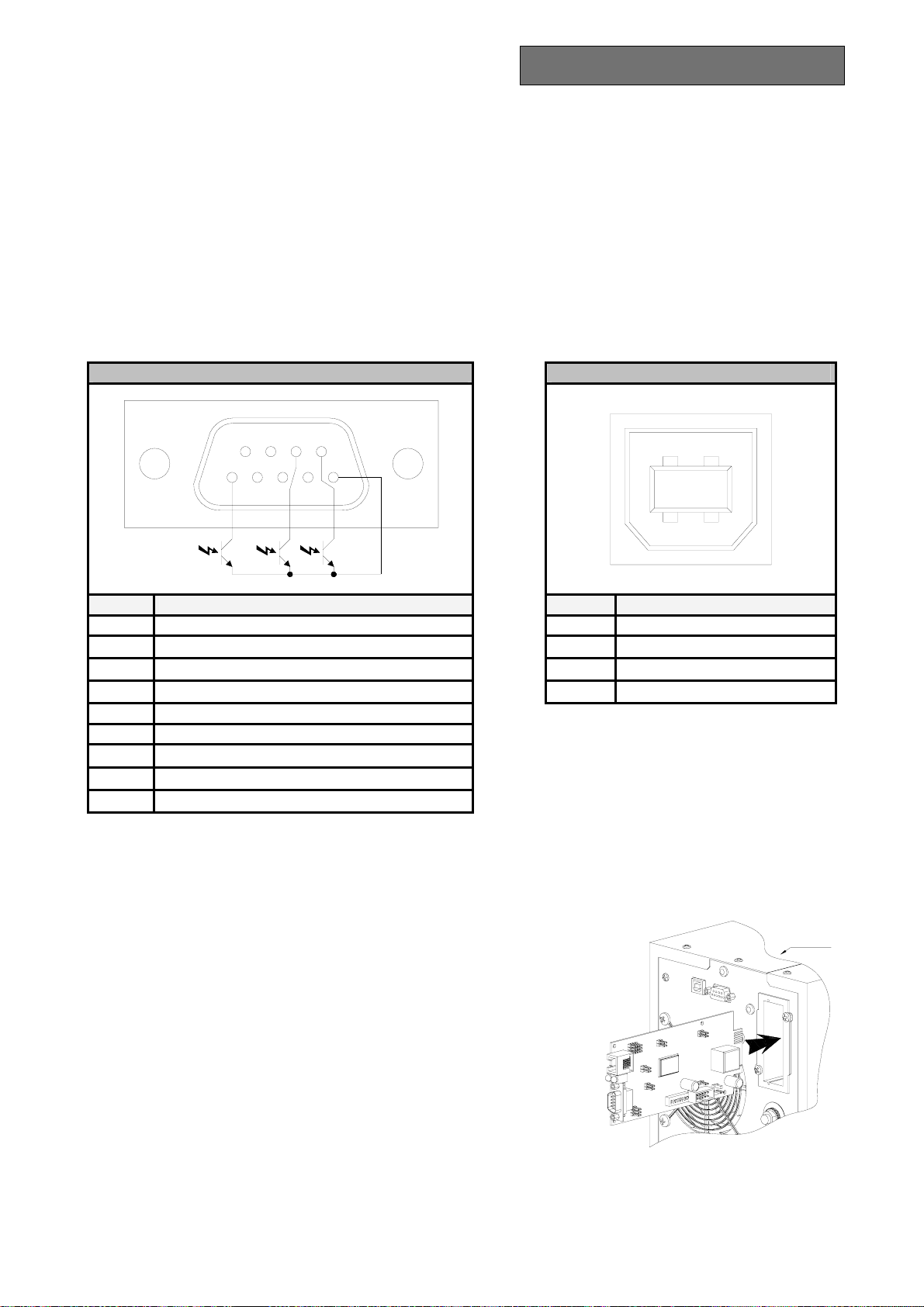
COMMUNICATION PORTS
The following communication ports are found on the rear of the UPS (see UPS Views):
¾ RS232 connector
¾ USB connector
¾ Expansion slots for additional COMMUNICATION SLOT interface cards
RS232 and USB connectors
RS232 CONNECTOR USB CONNECTOR
USE
7
986
34
21345
12
PIN # SIGNAL PIN # SIGNAL
1
2 TXD 2 D3 RXD 3 D+
4 4 GND
5 GND
6
7 +12Vdc interface power supply input
8
Contact closed: end of discharge early warning *
9
Contact closed: UPS stopped *
Contact closed: battery-powered operation *
* Optoisolated contact max. +30Vdc / 10mA
Communication Slot
1 VBUS
The UPS is provided with an expansion slot for optional
communication cards (see the figure to the side) that enable the
machine to carry out dialog using the main communication standards.
Some examples:
• Second RS232 port
• Serial port duplexer
• Ethernet network agent with TCP/IP, HTTP and SNMP protocol
• RS232 + RS485 port with JBUS / MODBUS protocol
For more information on the accessories available, consult the
manufacturer’s web site.
UPS
57
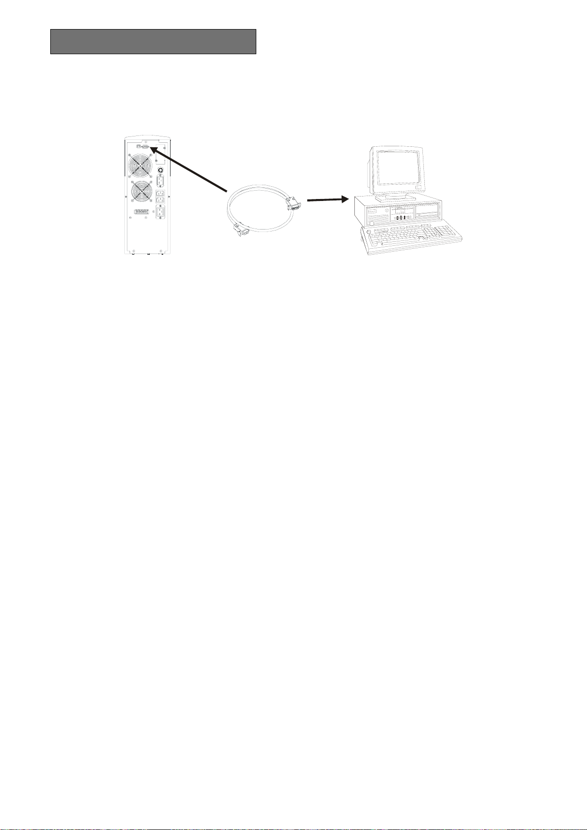
USE
SOFTWARE
UPS
RS232
Monitoring and control software
The UPSmon software provides effective and intuitive management of the UPS, displaying all the most
important information, such as input voltage, load applied, and battery capacity.
It is also able to automatically effect operations such as shutdown, transmission of e-mails, SMS and network
messages when particular events that can be selected by the user occur.
Installation procedure:
PC
• Connect the UPS’s RS232 communication port to a COM communication port on the PC by means of
the serial cable provided * or connect the USB port on the UPS to a USB port on the PC using a USB
standard cable*.
• Insert the CD-ROM and select the desired operating system.
• Follow the instructions of the installation program.
• For more detailed information about installation and use, see the software user manual in the Manuals
folder of the CD-ROM supplied.
To check if a more up to date version of the software is available, visit the manufacturer’s web site.
Configuration software
The UPSTools software may be used for configuration and full display of the parameters and status of the
UPS through the RS232 serial port.
For a list of the possible configurations at the user’s disposal, see the section UPS Configuration.
Installation procedure:
• Connect the RS232 communication port of the UPS to a COM communication port on the PC by means
of the serial cable provided*.
• Follow the instructions on installation found in the software user manual in the UPSTools folder of the
CD-ROM supplied.
To check if a more up to date version of the software is available, visit the manufacturer’s web site.
*
You are advised to use a cable of max. length 3 metres.
58

A
BATTERY PACK
REPLACEMENT OF THE BATTERY PACK
As indicated in the presentation, the UPS is provided with a dedicated battery pack that permits easy
replacement of the batteries (hot swap), entirely safely for the operator, thanks to the protected connection
system.
WARNING: for your own safety and that of your product, it is important that you follow the instructions
given below exactly.
WHEN THE BATTERY PACK IS DISCONNECTED, THE LOADS CONNECTED
TO THE UPS ARE NOT PROTECTED AGAINST A MAINS FAILURE.
THE BATTERY PACK IS VERY HEAVY. TAKE ALL DUE CARE WHEN
PERFORMING SUBSTITUTION.
1 - The battery pack is located behind the front panel of the UPS. Take the
panel centrally by the sides and pull gently outwards as shown in the
figure to the side. In doing so, do not force the panel fastening pins too
much.
2 - Put the manual bypass switch located under the front panel to position
“II” (see figure to the side).
WARNING: in this condition, the load is powered by the bypass and
the display must show the message FAULT: C02.
WARNING: For proper operation of the UPS, it is recommended
that you replace the battery pack only with the UPS switched on.
3 - The battery pack is connected to the rest of the UPS by means of a
cable with terminal. See the figure on the side:
press the 2 tabs on the sides of the terminal (
) and take it out
pulling gently upwards. With your thumbs, together press the 2
B
fastening catches (
fingers into the slot located under the connector (
) and, keeping them pressed, put your index
C
).
4 - Maintaining the position described in the previous step, take out the
battery pack pulling outwards as shown in the figure to the side.
Take great care when extracting the battery pack as it is very heavy.
WARNING: the new battery pack and the one to be replaced must
contain the same number and type of batteries (see the label next to the
connector on the battery pack).
5 - Insert the new battery pack in its seat by sliding until it clicks into the
UPS. Connect the cable with terminal again to its connector, put the switch back to position “I” and
close the front panel. Make sure that the display returns to the normal display mode.
A
A
B
A
W
!
G
N
I
N
R
A
W
!
G
See the instruction
manual before
disconnect ing the
battery connector
Press the swit ch in
the position ‘II’
before changi ng
the battery pack
C
N
I
N
R
G
!
W
A
R
N
I
N
G
!
W
A
R
N
N
I
B
59

PROBLEM SOLVING
Very often improper operation of the UPS does not indicate a failure, but is due solely to banal problems,
drawbacks or lack of attention.
You are therefore recommended to carefully consult the table below which summarizes the information
needed to solve the most common problems.
PROBLEM POSSIBLE CAUSE SOLUTION
MAIN SWITCH NOT
PRESSED
Press the main switch on the front panel.
THE DISPLAY DOES NOT
LIGHT
THE DISPLAY IS ON BUT
THE LOAD IS NOT BEING
POWERED
THE UPS IS WORKING ON
BATTERY POWER DESPITE
THE FACT THAT MAINS
VOLTAGE IS PRESENT
THE BATTERY PACK
CONNECTOR IS
DISCONNECTED
MAINS CONNECTION
CABLE MISSING
MAINS VOLTAGE MISSING
(BLACK-OUT)
INPUT THERMAL
PROTECTION TRIGGERED
THE UPS IS IN STAND-BY
MODE
THE STAND-BY OFF MODE
IS SELECTED
CONNECTION TO THE LOAD
IS MISSING
INPUT THERMAL
PROTECTION TRIGGERED
INPUT VOLTAGE OUTSIDE
THE PERMITTED VOLTAGE
RANGE FOR MAINS-
POWERED OPERATION
Connect the battery pack connector, following the
instructions in the section “REPLACEMENT OF THE
BATTERY PACK”.
Check that the power cord is connected properly.
Check that there is live voltage in the outlet the UPS is
connected to (by testing, for example, with a table
lamp).
Reset the protection by pressing the button on the rear
of the UPS (CIRCUIT BREAKER).
WARNING
: Check that there is no overloading on the
UPS outlet.
Press the “ON” button on the front panel to power the
loads.
You must change mode.
STAND-BY OFF mode (back-up) powers the loads
only when there is a black-out.
Check the connection to the load.
Reset the protection by pressing the button on the rear
of the UPS (CIRCUIT BREAKER).
WARNING
: Check that there is no overloading on the
UPS outlet.
Problem depending on the mains. Wait for the input
mains to come back into tolerance. The UPS will
automatically go back into mains-powered operation.
THE UPS DOES NOT COME
ON AND THE DISPLAY
SHOWS ONE OF THE
CODES: A06, A08
THE DISPLAY SHOWS
CODE: A11
60
UPS TEMPERATURE LESS
THAN 0°C
INPUT RELAY STUCK
Check the UPS surrounding ambient temperature; if too
low, bring temperature to above the minimum threshold
(0°C).
This fault does not produce any particular malfunctions.
However, if the problem occurs again the next time the
UPS is switched on, get in touch with the service centre.

PROBLEM POSSIBLE CAUSE SOLUTION
THE BUZZER SOUNDS
CONTINUOUSLY AND THE
DISPLAY POSTS ONE OF
THE CODES: A54, F50, F51,
F52, F55, L50, L51, L52
THE DISPLAY SHOWS
CODE: A61
THE LOAD APPLIED TO THE
UPS IS TOO HIGH
BATTERIES NEED TO BE
REPLACED
PROBLEM SOLVING
Lower the load to inside the 100% threshold (or user
threshold in case of code A54).
Replace the battery pack with a new one (as indicated in
the chapter BATTERY PACK).
THE DISPLAY SHOWS
CODE: A62
THE DISPLAY SHOWS
CODE: A63
THE BUZZER SOUNDS
CONTINUOUSLY AND THE
DISPLAY POSTS ONE OF
THE CODES: F03, F05, F07,
F10, F13, F21, F40, F41, F42,
F43
THE BUZZER SOUNDS
CONTINUOUSLY AND THE
DISPLAY POSTS ONE OF
THE CODES: F04, L04
THE BUZZER SOUNDS
CONTINUOUSLY AND THE
DISPLAY POSTS ONE OF
THE CODES: F53, L53
THE BUZZER SOUNDS
CONTINUOUSLY AND THE
DISPLAY POSTS ONE OF
THE CODES: F60, L03, L05,
L07, L10, L13, L20, L21,
L40, L41, L42, L43
THE DISPLAY SHOWS ONE
OF THE CODES: C01, C02,
C03
BATTERY PACK MISSING
OR NOT CONNECTED
BATTERIES ARE
DISCHARGED; THE UPS IS
WAITING FOR THE
BATTERY VOLTAGE TO
EXCEED THE SET
THRESHOLD
A UPS MALFUNCTION IS
TAKING PLACE;
SHUTDOWN IMMINENT
TEMPERATURE OF THE
HEAT SINKS INSIDE THE
UPS IS TOO HIGH
FAULT DETECTED ON ONE
OR MORE LOADS POWERED
BY THE UPS
A UPS MALFUNCTION HAS
OCCURRED
A REMOTE COMMAND IN
PROGRESS
Check that the battery pack is inserted and connected
correctly (see the chapter BATTERY PACK).
Wait for the batteries to recharge or manually force
switching-on by holding the “ON” button down for at
least 2 sec.
If it is possible to power down the load, switch off the
UPS and switch it on again; if the problem occurs again,
contact the service centre.
Check that the UPS surrounding ambient temperature is
not in excess of 40°C.
Disconnect all the loads and connect them up again one
by one to identify the faulty one.
If it is possible to power down the load, switch off the
UPS and switch it on again; if the problem occurs again,
contact the service centre.
If undesired, check the position of the manual bypass
switch or status of the control inputs of an optional
contacts card.
61

PROBLEM SOLVING
ALARM CODES
By using a sophisticated self-test system, the UPS can check and report on the display panel any problems
and/or failures that could occur during normal operation of the equipment. In case of a problem, the UPS
signals the event by posting on the display the code and type of alarm present (FAULT and/or LOCK).
FAULT
The FAULT type reports may be divided into three categories:
¾ Failures: these are “minor” problems that do not result in the UPS stopping but they limit its
performance or prevent certain features being used.
CODE DESCRIPTION
A06
A08
A11
A54
ON LINE: load > of the user threshold - ECO: load > 16A *
A61
A62
A63
¾ Alarms: these problems are more critical than the failures because – if they continue – they could
cause the UPS to stop, even in a very short time frame.
CODE DESCRIPTION
F03
F04
F05
F07
F10
Input fuse broken or input relay stuck (does not close)
F13
F21
F40
F41
F42
F43
F50
F51
F52
F53
F55
Waiting for load reduction before return to inverter
F60
Temperature sensor1 less than 0°C
Temperature sensor2 less than 0°C
Input relay stuck (does not open)
Batteries need replacement
Battery pack missing or not connected
Waiting for batteries to recharge
Auxiliary power supply incorrect
High temperature on heat sinks
Temperature Sensor1 broken
Temperature Sensor2 broken
Capacitor precharging failure
Capacitor bank overvoltage
Inverter overvoltage
D-C voltage on output
Inverter voltage not right
Inverter undervoltage
Overload: load > 103%
Overload: load > 110%
Overload: load > 150%
Short-circuit
Battery overvoltage
62

PROBLEM SOLVING
¾ Commands in progress: Indicates presence of a remote command in progress.
CODE DESCRIPTION
C01
C02
C03
C04
LOCK
The LOCK (block) type report signals are usually preceded by an alarm signal and, on account of their
importance, result in the inverter being switched off and the load being powered through the bypass line (the
procedure is excluded in case of lockouts due to strong and persistent overloads and lockouts following a
short-circuit).
CODE DESCRIPTION
L03
L04
L05
L07
L10
L13
L20
L21
L40
L41
L42
L43
L50
L51
L52
L53
* In ECO mode, the load is normally powered by the bypass. Therefore, in the presence of a load of constant power,
the current absorbed depends on the mains voltage, which may accordingly be in excess of the value allowed by the
input plug and the protection upstream.
When this situation arises, the UPS reports a failure which automatically disappears if the input voltage increases
and/or the output load is reduced.
Input fuse broken or input relay stuck (does not close)
Remote shutdown command
Remote load on bypass command
Remote switch-on command
Battery test in progress
Auxiliary power supply incorrect
High temperature on heat sinks
Temperature Sensor1 broken
Temperature Sensor2 broken
Capacitor precharging failure
Capacitor bank undervoltage
Capacitor bank overvoltage
Inverter overvoltage
D-C voltage on output
Inverter voltage not right
Inverter undervoltage
Overload: load > 103%
Overload: load > 110%
Overload: load > 150%
Short-circuit
63

5 -
TECHNICAL DATA TABLE
MODELS
INPUT
3300 4000
Nominal voltage [Vac] 220 / 230 / 240
Accepted range [Vac] 0 ÷ 276
Voltage range ruling out battery intervention [Vac]
Maximum: 276
[Vac]
Minimum: 164 ÷ 84 (from 100% to 50% of load in
linear mode)
[Vac]
Return to mains-powered operation: 180
Nominal frequency [Hz] 50 - 60 +5
Maximum current
Nominal current
(1)
(2)
Power factor
Current distortion @ maximum load
[A] 15 16
[A] 11 12
≥ 0.98
≤ 7%
BYPASS
Accepted voltage range for switching [Vac] 180 ÷ 264
Accepted frequency range for switching Frequency selected ±5 %
Switching time [msec] Typical: 2 - Maximum: 4
BATTERY
Back-up time [min / W] 6’ / 2300 5’30 / 2400
No. batteries / V / Ah 9 / 12 / 7 high rate discharge
Recharge time [h] 4 ÷ 8
OUTPUT
Nominal voltage
Static variation
(3)
Dynamic variation
(7)
(4)
[Vac] 220 / 230 / 240 ±1.5%
1.5%
≤ 5% in 20 msec
Waveform Sinusoidal
Voltage distortion @ linear load
Voltage distortion @ distorting load
Frequency
(5)
Current crest factor
50 or 60 Hz selectable
≤ 3%
≤ 6%
≥ 3 : 1
Nominal power [VA] 3300 4000
Nominal power [W] 2300 2400
MISCELLANEOUS
Leakage current to earth [mA]
≤ 1
AC/AC efficiency 92%
Ambient temperature
(6)
[°C] 0 – 40
Humidity < 90% non-condensing
Protections Excessive battery discharge – Overcurrent – short-circuit
– Overvoltage – undervoltage - thermal
Safety compliance EN 62040-1-1, directives 73/23/EC and 93/68/EC
EMC compliance EN 50091-2 cl.B directives 2004/108/EC, 93/68/EC and
89/336/EC
Hold-up time [msec]
≥ 40
Noise level < 40 dB(A) at 1 mt.
Dimensions H x L x D [mm] 455 x 175 x 520
Weight [Kg] 38 38
64

6 -
TECHNICAL DATA TABLE
OVERLOAD TIMES
OPERATION POWERED BY
BYPASS INVERTER
100% < Load ≤ 110%
110% < Load ≤ 150%
Load > 150%
Activates bypass after 2 sec
Stoppage after 120 sec
Activates bypass after 2 sec
Stoppage after 4 sec
Activates bypass instantaneously
Stoppage after 1 sec
(1)
@ nominal load, minimum voltage of 164 Vac, battery charging
(2)
@ nominal load, nominal voltage of 230 Vac, battery charging
(3)
Mains/Battery @ load 0% -100%
(4)
@ Mains/battery/mains @ resistive load 0% / 100% / 0%
(5)
If the mains frequency is within ± 5% of the value selected, the UPS is synchronized with the mains. If the
frequency is outside the tolerances or operation is battery-powered, the frequency is the selected frequency +
(6)
20 - 25 °C for longer battery life
(7)
To maintain the output voltage inside the precision range indicated, a recalibration may be necessary after a long
period in operation
Stoppage after 60 sec
Stoppage after 4 sec
Stoppage after 0.5 sec
0.1%
65

66

D
BEDIENUNGSANLEITUNG
D
67

EINLEITUNG
Wir danken Ihnen dafür, daß Sie unserem Produkt den Vorzug gegeben haben.
Die Herstellerfirma ist völlig auf die Entwicklung und Produktion von unterbrechungsfreien
Stromversorgungen (UPS) spezialisiert. Die USV-Systeme aus dieser Serie sind Produkte von hochwertiger
Qualität, die aufmerksam entworfen und gebaut wurden mit dem Ziel, die besten Leistungen zu
gewährleisten.
Nach vorheriger AUFMERSAMER UND SORGFÄLTIGER LEKTÜRE DES VORLIEGENDEN
HANDBUCHS kann dieses Gerät durch jedwede Person installiert werden
Dieses Handbuch enthält detaillierte Anweisungen zur Benutzung und Installation der USV.
Um Informationen über die Benutzung und die besten Leistungen Ihres Geräts zu erzielen, muss
dieses Handbuch mit Sorgfalt in der Nähe der USV aufbewahrt und VOR DEREN GEBRRAUCH ZU
RATE GEZOGEN WERDEN.
© Vorbehaltlich der Autorisierung durch die Herstellerfirma, ist die Reproduktion jedweden Teils des vorliegenden Handbuchs,
auch partiell, ist verboten.
Zum Zwecke der Verbesserung behält der Hersteller sich das Recht vor, das beschriebene Produkt jederzeit und ohne Vorwarnung
abzuändern.
Microsoft, Windows und das Windows Logo sind Warenzeichen oder registrierte Warenzeichen der Microsoft Corporation in den
Vereinigten Staaten und/oder anderen Ländern.
68

INHALTSVERZEICHNIS
DARSTELLUNG 70
USV ANSICHTEN 71
ANSICHT DISPLAY MASKE 72
INSTALLATION 73
ÖFFNUNG DER VERPACKUNG UND ÜBERPRÜFUNG DEREN INHALTS 73
TURM AUSFÜHRUNG 74
RACK AUSFÜHRUNG 75
BENUTZUNG 76
ANSCHLUESSE UND ERSTES EINSCHALTEN 76
EINSCHALTEN IM NETZBETRIEB 76
BATTERIEBETRIEB 76
AUSSCHALTEN DER USV 76
ANGABEN AUF DER DISPLAY TAFEL 77
Anzeiger für den USV Zustand 77
Bereich zur Visualisierung von Messwerten 78
Konfigurationsbereich 79
BETRIEBSART 80
KONFIGURATION DER USV 81
KOMMUNIKATIONSSCHNITTSTELLEN 83
Schnittstellen RS232 und USB 83
Kommunikationsslot 83
SOFTWARE 84
Überwachungs- und Kontrollsoftware 84
Konfigurationssoftware 84
BATTERIEBLOCK 85
ERSATZ DES BATTERIEBLOCKS 85
PROBLEMLÖSUNG 86
ALARMCODES 88
TABELLE MIT TECHNISCHEN DATEN 90
69

DARSTELLUNG
Die neue USV 3300 - 4000 Familie ist unter Berücksichtigung der Vielseitigkeit ausgearbeitet worden. Diese
USV Systeme können je nach Erfordernisse sowohl als Tower (Turm) Ausführung als auch als Rack
(Einschub) Ausführung (mit Hilfe des eigens dafür vorgesehenen optionalen Griff Kits) installiert werden.
Hier unten wird das Produkt in den 2 verschiedenen Ausführungen dargestellt:
Tower Rack
Ferner ist die USV mit einem zweckbestimmten Batterieblock versehen, der dank des geschützten
Anschlusssystems einen leichten Ersatz der Batterien im warmen Zustand (hot swap) in aller Sicherheit
erlaubt.
Nennleistung [VA] 3300 4000
Nennspannung [Vac] 220 / 230 / 240
Abmessungen H x B x T [mm]
Gewicht [kg] 38
(1)
In der Rack Version mit den eingebauten Griffen ist das Mass H anders: 483mm x 175mm x 520mm (H x B x T)
Anmerkung: 175mm = 4U
483mm = 19”
3300 4000
(1)
455 x 175 x 520
70

V
USV ANSICHTEN
DARSTELLUNG
Entkupplungsschlitze
Herausnehmbare/drehbare Displaymaske
manueller Bypass
Schalter
Kabel mit Klemme
Batterieblock
Kommunikations-
schnittstelle USB
Hauptschalter
Abnehmbare Frontplatte
orderansicht
(abgenommene Frontplatte) (mit Frontplatte)
Kommunikationsschnittstelle RS232
Rückansicht
Kühllüfter
Stecker
Batterieerwei-
terung
Erweiterungsslot
COMMUNICATION SLOT
Eingangsthermosschutz
Eingang IEC 16A
Ausgänge IEC 10A
Ausgang IEC 16A
71

DARSTELLUNG
ANSICHT DISPLAY MASKE
“SEL / SET”Taste
1
2
3
4
“ON”Taste
“STBY”Taste
1011
9
8
LCD
Display
1
Normalbetrieb
2
Netzbetrieb
3
Batteriebetrieb
4
Durch By-pass versorgte Last
5
Batterieautonomie Anzeiger
6
Ladeniveau Anzeiger
72
5 6 7
7
Konfigurationsbereich
8
Wartungsanforderung
9
Timer
10
Messwertanzeigebereich
11
Bereitschaft (stand-by) / Alarm

INSTALLATION
ÖFFNUNG DER VERPACKUNG UND ÜBERPRÜFUNG DEREN INHALTS
Nach der Öffnung der Verpackung zuerst mit der Überprüfung des Inhalts vorgehen.
Die Verpackung muss beinhalten:
USV
2 Plastikabdeckungen
(obere Tafeln)
Versorgungskabel
(Schuko Stecker– Steckbuchse IEC 16A)
2 Anschlusskabel IEC 10A
2 Plastikschlüssel für
Displayentkupplung
Serielles Kabel RS232
Fliegender Stecker IEC 16A
Benutzer Handbuch + CD-ROM Software
U
s
e
r
'
s
m
a
n
u
a
l
73

INSTALLATION
TURM AUSFÜHRUNG
In diesem Kapitel werden die Vorgänge zur Vorbereitung der USV auf die Benutzung als Turm Ausführung
beschrieben.
ACHTUNG: für Ihre Sicherheit und zum Schutz Ihres Produkts ist es erforderlich, die hier folgenden
Informationen sorgfältig zu befolgen.
VOR DER AUSFÜHRUNG DER FOLGENDEN HANDLUNGSABFOLGE
SICH VERGEWISSERN, DASS DIE USV VOLLKOMMEN
ABGESCHALTET UND WEDER ANS STROMNETZ NOCH AN
IRGENDEINE LAST ANGESCHLOSSEN IST.
Nach dem Herausziehen aus der Verpackung zeigt sich die USV bereits vorbereitet für die Installation in der
Turm Konfiguration.
Zur Vervollständigung jener Konfiguration reicht es aus, die beiden mitgelieferten Plastikabdeckungen im
oberen Teil der USV einzubauen, wobei die folgenden Angaben beachtet werden müssen:
Die 2 Abdeckungen haben ein Einspannbefestigungssystem:
die Bohrungen, die eigens für den Einbau der Abdeckungen im
oberen Teil der USV vorgesehen sind, ausmachen und sie mit
grösster Vorsicht einhaken, wobei ein leichter Druck auszuüben ist
(siehe seitliche Abbildung).
Anmerkung: da die Abdeckungen vollkommen gleich sind, können
beide problemlos in beiden Bereichen (vorn / hinten) auf der
oberen Seite der USV eingebaut werden.
74

INSTALLATION
RACK AUSFÜHRUNG
Im folgenden wird die Handlungssequenz beschrieben, um die USV in eine RACK Version zu verwandeln
ACHTUNG: für Ihre Sicherheit und zum Schutz Ihres Produkts ist es erforderlich, die hier folgenden
Informationen sorgfältig zu befolgen.
VOR DER AUSFÜHRUNG DER FOLGENDEN HANDLUNGSABFOLGE SICH
VERGEWISSERN, DASS DIE USV VOLLKOMMEN ABGESCHALTET UND WEDER
ANS STROMNETZ NOCH AN IRGENDEINE LAST ANGESCHLOSSEN IST.
1 - Zuerst ist es erforderlich, die 4 Füsse auf
dem Boden der USV auszubauen. Die USV
mit grösster Vorsicht
in horizontaler
Position bringen und mit einem kleinen
Schneidschraubenzieher den Bolzen im
Fusszentrum leicht anheben. Nach dem
Anheben den Fuss vom USV Boden
abziehen. Dieselben Vorgänge für alle
übrigen Füsse wiederholen. Auf der Seite
wird die genau zu befolgende Sequenz
dargestellt:
12
2 - Nach dem Ausbau der Füsse muss mit der Drehung der Display Maske
vorangeschritten werden Die mitgelieferten Schlüssel in die
Entkupplungsschlitze einstecken, die sich auf den Seiten der Display
Maske befinden und einen leichten Druck, der zur Entkupplung der
Maske von der USV ausreicht, ausüben, wie auf der seitlichen
Abbildung hervorgehoben wird.
3 - ACHTUNG: Die Display Maske ist über das eigens dafür vorgesehene Kabel mit der USV
verbunden. Es ist daher erforderlich, die Maske mit grösster Vorsicht abzuziehen und ein heftiges
Reissen sowie andere brüske Bewegungen zu vermeiden, damit mögliche Schäden an dem Display
und/oder an der USV vermieden werden. KEINESFALLS VERSUCHEN, DIE DISPLAY MASKE
VON DER USV ZU TRENNEN.
4 - Die Maske um 90° gegen den Uhrzeigersinn drehen und sie erneut an die USV einhängen, indem sie
leicht in das eigens dafür vorgesehene Gehäuse eingesetzt wird, bis ein leichtes Einrasten der Maske,
die in Position verbleibt, zu vernehmen ist.
5 - Die USV mit grösster Vorsicht
um 90° im Uhrzeigersinn drehen.
6 - An dieser Stelle mit der USV in horizontaler Position die Griffe an den
Seiten der USV mit Hilfe der eigens dafür vorgesehenen Schrauben
befestigen, wie in der Abbildung auf der Seite gezeigt wird. (Griffe und
Schrauben sind in dem optionalen Griff Kit enthalten)
ANMERKUNG: Die USV ist kompatibel mit dem Einbau in Standard Rack Schränken 600mm x 800mm
oder in Schränken mit grösseren Abmessungen (was die Tiefe betrifft). Aufgrund des
Gewichts der USV ist es bei der Rack Installation obligatorisch, Haltebügel zu benutzen
(Führung mit L Halterung). Aus demselben Grund ist es auch ratsam, die USV in dem
niedrigen Teil des Rack Schranks einzubauen.
75

BENUTZUNG
ANSCHLUESSE UND ERSTES EINSCHALTEN
1) Einen 16A Schütz mit einer Eingriffskurve B oder C vor dem Gerät installieren.
2) Das mitgelieferte Versorgungskabel an die USV in der Eingangssteckbuchse IEC 16A anschliessen.
3) Das Versorgungskabel der USV ans Stromnetz anschliessen.
4) Den Hauptschalter auf der Frontplatte betätigen.
5) Nach einem Augenblick aktiviert sich die USV, das Display schaltet sich ein, es wird ein Beep
ausgesendet und die Ikone
Die USV ist in Bereitschaft (Stand-by Zustand): dies bedeutet, dass die USV in einem Zustand mit
niedrigstem Verbrauch ist. Der Mikrocontroller wird versorgt und führt die Überwachungs- und
Autodiagnose Funktion aus; die Batterien werden aufgeladen; alles ist vorbereitet, um die USV zu
aktivieren. Es liegt ein Stand-by Zustand auch im Batteriebetrieb vor, vorausgesetzt dass der Timer
aktiviert worden ist.
6) Das/Die zu speisende/n Gerät/e an die Steckbuchsen auf der Rückseite der USV anschliessen, wofür
das mitgelieferte Kabel oder auf jeden Fall ein Kabel mit einer maximalen Länge von 10 Metern zu
benutzen ist.
ACHTUNG: an die IEC 10A Steckbuchsen keine Geräte anschliessen, die mehr als 10A entnehmen..
Für Geräte, die jenen Bedarf übersteigen, ausschliesslich die IEC 16A Steckbuchse benutzen.
7) Die vorgenommenen Einstellungen am Display überprüfen (siehe Kapitel: Konfigurationsbereich)
blinkt.
EINSCHALTEN IM NETZBETRIEB
1) Die “ON” Taste betätigen. Nach der Betätigung schalten sich alle Ikonen auf dem Display ein, und
die USV sendet ein Beep aus.
2) Das an die USV angeschlossene Gerät einschalten.
Nur für das erste Einschalten: nach Ablauf von zirka 30 Sek. die einwandfreie Funktionsweise der USV
überprüfen:
1. Ein Black-out durch Öffnung des vor der USV angeschlossenen Schalters simulieren.
2. Die Last muss weiter gespeist werden, die Ikone
auf dem Display muss sich einschalten und
es muss ein Beep alle 4 Sekunden vernommen werden.
3. Nach dem Schliessen des Schalters vor der USV muss die Funktionsweise der USV in den
Netzbetrieb zurückkehren.
BATTERIEBETRIEB
1) Den Hauptschalter auf der Frontplatte betätigen.
2) Die “ON” Taste für mindestens 5 Sekunden gedrückt halten. Alle Ikonen auf dem Display schalten
sich für eine Sekunde ein, und die USV sendet ein Beep aus.
3) Die an die USV angeschlossenen Geräte einschalten.
AUSSCHALTEN DER USV
Zum Ausschalten der USV die “STBY” Taste für mindestens 1,5 Sekunden gedrückt halten. Die USV kehrt
in den Stand-by Zustand zurück, und die Ikone
a. Wenn das Netz vorhanden ist, muss zum völligen Ausschalten der USV der Hauptschalter betätigt
werden, so dass der Schalter in die ursprüngliche Position (erhobene Position) zurückgebracht wird.
b. Wenn die USV im Batteriebetrieb ist und der Timer nicht eingestellt worden ist, schaltet sie sich
nach 5 Sekunden automatisch vollkommen ab. Wenn der Timer hingegen eingestellt worden ist, ist
es zum Ausschalten der USV erforderlich, die “STBY” Taste für mindestens 5 Sekunden gedrückt zu
halten. Wenn gewünscht wird, dass die USV bei Netzrückkehr völlig ausgeschaltet bleibt, ist es
notwendig, den Hauptschalter zu betätigen (siehe Punkt a.).
fängt an zu blinken:
76

BENUTZUNG
ANGABEN AUF DER DISPLAY TAFEL
In diesem Kapitel werden alle Informationen, die auf dem LCD Display visualisiert werden können, genau
beschrieben.
Zum besseren Verständnis können die visualisierten Informationen in drei Hauptgruppen unterteilt werden:
¾ Anzeiger für den USV Zustand
¾ Bereich zur Visualisierung von Messwerten
¾ Konfigurationsbereich
Anzeiger für den USV Zustand
IKONE ZUSTAND BESCHREIBUNG
Ständig
leuchtend
Zeigt an, dass eine Störung vorhanden ist
Blinkend Die USV ist im Stand-by Zustand.
Ständig
leuchtend
Zeigt eine einwandfreie Funktionsweise an
Ständig
leuchtend
Blinkend
Ständig
leuchtend
Blinkend
Die USV funktioniert zwar im Netzbetrieb, aber die Ausgangsspannung
Die USV funktioniert zur Zeit im Batteriebetrieb. Wenn die USV sich
in diesem Zustand befindet, sendet sie in regelmässigen Intervallen von
Alarm Batterie fast entladen. Zeigt an, dass die Autonomie der Batterien
zu Ende geht. In diesem Zustand sendet die USV in regelmässigen
Die USV funktioniert zur Zeit im Netzbetrieb
ist nicht mit der Netzspannung synchronisiert
4 Sek. ein akustisches Signal (Beep) aus.
Intervallen von 1 Sek. ein Beep aus.
Ständig
leuchtend
Zeigt an, dass die an die USV angeschlossenen Lasten durch den By-
pass gespeist werden.
Dynamisch Zeigt den Prozentsatz der geschätzten Autonomie an
Dynamisch
Zeigt den % der an die USV angelegten Last im Vergleich zum
Nennwert an
Blinkend Ein Wartungseingriff ist erforderlich
Ständig
leuchtend
Blinkend
Zeigt an, dass der Timer aktiviert ist (programmiertes Ein- oder
Ausschalten). Der Timer ist über die mitgelieferte Software ein-
/aussschaltbar .
Es fehlt 1 Minute bis zum erneuten Einschalten der USV oder 3
Minuten bis zu ihrem Ausschalten
77

BENUTZUNG
Bereich zur Visualisierung von Messwerten
Auf dem Display können in Abfolge die wichtigsten Messwerte der USV visualisiert werden.
Beim Einschalten der USV zeigt das Display den Wert der Netzspannung an.
Zum Übergang auf eine andere Visualisierung die “SEL / SET” Taste wiederholt betätigen, bis dass der
gewünschte Messwert erscheint.
Falls eine Störung / ein Alarm (FAULT) oder eine Blockierung (LOCK) eintreten sollte, wird automatisch
auf dem Display der entsprechende Alarmtyp und –code visualisiert.
Im folgenden sind einige Beispiele abgebildet:
GRAPHISCHES
BEISPIEL
(1)
BESCHREIBUNG
GRAPHISCHES
BEISPIEL
(1)
BESCHREIBUNG
Netzspannung
Netzfrequenz
Ausgangsspannung der
(1)
Die Werte auf den Bildern der Tabelle sind rein indikativ.
(2)
Die FAULT / LOCK Codes können nur visualisiert werden, wenn sie momentan aktiv sind (Präsenz einer Störung /
eines Alarms oder einer Blockierung).
USV
Frequenz der
Ausgangsspannung
Restliche
Batterieautonomie
Prozentsatz der
Batterielast
Gesamtspannung der
Batterien
Prozentsatz der
angelegten Last
Durch die Last
entnommener Strom
Temperatur des
Kühlsystems der USV
Innenelektronik
Störung / Alarm
wird der entsprechende
Code visualisiert.
(2)
Blockierung
der entsprechende Code
visualisiert.
: es wird
(2)
: es
78

BENUTZUNG
Konfigurationsbereich
Im Konfigurationsbereich sind die wichtigsten Parameter für die Funktionsweise der USV in Gruppen
zusammengestellt, und es wird deren aktueller Zustand visualisiert. Die in diesem Bereich beinhalteten
Parameter können abgeändert werden durch direktes Einwirken von der Display Tafel aus.
EINSTELLBARE PARAMETER:
Frequenz: Frequenz der Ausgangsspannung
Frequenz
Spannung: Ausgangsspannung
Modalität: Betriebsmodus der USV
Spannung
Modalität
Das Bild auf der Seite stellt den Displaybereich für die
Einstellungen (Konfigurationsbereich) mit den drei
hervorgehobenen einstellbaren Parametern dar.
Wie geht man vor:
Um Zugang zum Konfigurationsbereich zu erhalten, die “SEL / SET” Taste für mindestens 2 Sek.
gedrückt halten.
Die Schrift “SET” leuchtet auf, und es erscheint ein nach links zeigender Pfeil ( ► ) für Frequenz.
Der Pfeil zeigt die gewählte Einstellung an. Um die Wahl des abzuändernden Parameter zu
verändern, die “SEL / SET” Taste betätigen.
Um die gewählte Position zu verändern die “ON” Taste betätigen.
Zum Verlassen des Konfigurationsbereichs die “SEL / SET” Taste für mindestens 2 Sek. gedrückt
halten.
MOEGLICHE EINSTELLUNGEN
Frequenz: □ 50 Hz □ 60 Hz □ Ausgeschaltet (automatiche Frequenzerkennung)
Spannung: □ 220 V □ 230 V □ 240 V
Modalität: □ ON LINE □ ECO □ SMART □ STBYOFF
ANMERKUNG: Um die Konfigurationsänderung der Ausgangsfrequenz wirksam werden zu lassen, ist es
erforderlich, die USV völlig auszuschalten und sie (über den Hauptschalter) erneut einzuschalten.
DIE PARAMETER SPANNUNG UND AUSGANGSFREQUENZ MUESSEN
KOMPATIBEL SEIN MIT JENEN DER DURCH DIE USV VERSORGTE
LAST
79

BENUTZUNG
BETRIEBSART
Die Betriebsart, die den grössten Schutz für die Last gewährleistet, ist der ON LINE Modus (default), bei
welchem die Energie für die Last sich einer doppelten Konversion unterzieht; letztere wird am Ausgang auf
perfekte sinusförmige Art wiederhergestellt mit einer Frequenz und Spannung, die ganz unabhängig vom
Eingang durch eine präzise digitale Mikroprozessorüberwachung gesichert werden (V.F.I.). *
Neben dem traditionellen ON LINE Modus mit Doppelwandlung ist es möglich, die folgenden Betriebsarten
einzustellen:
¾ ECO (LINE INTERACTIVE)
¾ SMART ACTIVE (auf dem Display als “SMART” visualisiert)
¾ STAND-BY OFF (auf dem Display als “STBYOFF” visualisiert)
Zur Optimierung des Leistungsgrads wird die Last im ECO Modus normalerweise durch den Bypass
versorgt. Falls das Netz aus dem vorgesehenen Toleranzbereich tritt, schaltet die USV auf die normale ON
LINE Betriebsart mit Doppelkonversion um. Nach zirka fünf Minuten der Netzrückkehr in den
Toleranzbereich wird die Last erneut auf den Bypass umgeschaltet.
Falls der Anwender sich nicht für die geeigneteste Betriebsart (zwischen ON LINE und ECO) zu entscheiden
weiss, kann er die Wahl dem SMART ACTIVE Modus anvertrauen, in welchem die USV auf der Grundlage
einer Statistik,die über die Qualität des Versorgungsnetzes aufgestellt wurde, auf autonome Weise
entscheidet, in welcher Modalität sie sich konfiguriert.
In dem STAND-BY OFF Modus wird schliesslich die Betriebsart als Netzreserve erzielt:
bei vorhandenem Netz wird die Last nicht versorgt, während beim Eintreten eines Black-out die Last durch
den Wechselrichter über die Batterien versorgt wird.
Der rms Wert der Ausgangsspannung wird durch die präsise Mikroprocessorüberwachung unabhängig von der
*
Eingangsspannung bestimmt, während die Frequenz der Ausgangsspannung (im Innern einer der durch den Anwender
einstellbaren Toleranz) synchronisiert ist mit jener der Eingangsspannung, um die Benutzung des Bypass zu erlauben.
Ausserhalb dieser Toleranz ist die USV nicht synchronisiert, da sie sich auf die Nennfrequenz bringt, und der Bypass
ist nicht mehr benutzbar (free running mode).
80

BENUTZUNG
KONFIGURATION DER USV
Die folgende Tabelle stellt alle möglichen Konfigurationen dar, die der Anwender zur Verfügung hat, um die
USV am besten an seine eigenen Bedürfnisse anzupassen
LEGENDE:
Zeigt an, dass die Konfiguration ausser durch die mitgelieferte
=
=
FUNKTION BESCHREIBUNG
Ausgangs-
frequenz
Ausgangs-
spannung
Betriebs-
modalität
Einschaltverzug
Ausschalten
wegen minimaler
Last
Ausgangsnenn-
Wahl der Ausgangs-
Wahl einer der 4
Betriebsmodalitäten
Wartezeit bis zum
erneuten Einschalten
nach Netzrückkehr
Ausschalten der USV
im Batteriebetrieb,
wenn die Last unter
Konfigurationssoftware auch über einen Eingriff von der Display Tafel aus
abgeändert werden kann.
Zeigt an, dass die Konfiguration nur durch die mitgelieferte
Konfigurationssoftware abgeändert werden kann.
IM VROAUS
BESTIMMT
Wahl der
Auto
frequenz
nennspannung
verschiedenen
automatischen
Automatisches
1% liegt
230V
ON LINE
5 Sek.
Ausgeschaltet
MOEGLICHE KONFIGURATIONEN MODALITÄT
• 50 Hz
• 60 Hz
• Auto: automatische Erkennung von der
Eingangsfrequenz
• 220V
• 230V
• 240V
• 220 ÷ 240 in 1V Step
(nur über Software)
• ON LINE
• ECO
• SMART ACTIVE
• STAND-BY OFF
• Ausgeschaltet
• 1 ÷ 255 in 1 Sek. Step
• Eingeschaltet
• Ausgeschaltet
Autonomiebegrenzung
Warnung vor
Entladungsende
Maximale Zeit im
Batteriebetrieb
Restliche Zeit der
geschätzten
Autonomie für die
Warnung vor dem
Entladungsende
Ausgeschaltet
3 Min. 1 ÷ 255 in 1 Min. Step
• Ausgeschaltet (Batterie völlig entladen)
• 1 ÷ 65535 in 1 Sek. Step
81

BENUTZUNG
FUNKTION BESCHREIBUNG
Zeitintervall für den
Batterietest
Alarmschwell-
wert für
maximale Last
Display-
helligkeit
Akustischer
Alarm
Toleranz der
Eingangsfrequenz
Bypass
Spannungs-
schwellwerte
By-pass
Spannungs-
schwellwerte für
ECO
Eingriffsempfind-
lichkeit für ECO
Versorgung der
Last in Stand-by
Bypass
Betriebsart
automatischen
Batterietest
Wählt die
Überlastverbraucher-
grenze
Wählt das
Helligkeitsniveau des
LCD Displays
Wählt die
Betriebsmodalität des
akustischen Alarms
Wählt den Bereich,
der für die
Eingangsfrequenz , für
den Übergang auf den
Bypass und für die
Synchronisierung des
Ausgangs zulässig ist
Wählt den zulässigen
Spannungsbereich für
den Übergang auf den
Bypass
Wählt den zulässigen
Spannungsbereich für
den ECO Modus
Wählt die
Eingriffsempfindlich-
keit während des ECO
Modus
Versorgung der Last
auf Bypass mit
ausgeschalteter USV
(Stand-by Zustand)
Wählt die Benutzung
der Bypass Leitung
IM VORAUS
BESTIMMT
40 Stunden
MÖGLICHE KONFIGURATIONEN MODALITÄT
• Ausgeschaltet
• 8 ÷ 255 in 1 Stunden Step
103% 10 ÷ 103 in 1% Step
Maximal Minimal ÷ Maximal in 20 Step
Herabgesetzt
o
• Normal
• Herabgesetzt: setzt nicht ein wegen
momentanen Eingriffs des Bypass
VORGESCHRITTENE FUNKTIONEN
• ± 0.25%
± 5%
Niedr.: 180V
Hoch: 264V
Niedr.: 200V
Hoch: 253V
Normal
Ausgeschaltet
(Last NICHT
versorgt)
Normal
• ± 0.5%
• ± 0.75%
• ± 1 ÷ ±10 in 1% Step
Niedrig: 180 ÷ 200 in 1V Step
Hoch: 250 ÷ 264 in 1V Step
Niedrig: 180 ÷ 220 in 1V Step
Hoch: 240 ÷ 264 in 1V Step
• Niedrig
• Normal
• Hoch
• Ausgeschaltet (nicht versorgt)
• Eingeschaltet (versorgt)
• Normal
• Ausgeschaltet mit Synchronisierung
Eingang/Ausgang
• Ausgeschaltet ohne Synchronisierung
Eingang/Ausgang
82

BENUTZUNG
KOMMUNIKATIONSSCHNITTSTELLEN
Auf der Rückseite der USV (siehe Ansichten USV) sind die folgenden Kommunikationsschnittstellen
vorhanden:
¾ Schnittstelle RS232
¾ Schnittstelle USB
¾ Erweiterungsslot für zusätzliche Schnittstellenkarten COMMUNICATION SLOT
Schnittstellen RS232 und USB
SCHNITTSTELLE RS232 SCHNITTSTELLE USB
7
986
34
21345
12
PIN # SIGNAL PIN # SIGNAL
1
2 TXD 2 D3 RXD 3 D+
4 4 GND
5 GND
6
7 Schnittstellenversorgungseingang +12Vdc
8
9
geschlossener Kontakt: USV blockiert *
Kontakt geschlossen: Alarm Batterie fast entladen *
Kontakt geschlossen: Batteriebetrieb *
1 VBUS
* optoisolierter Kontakt max. +30Vdc / 10mA
Kommunikationsslot
Die USV ist mit einem Erweiterungsslot für optionale
Kommunikationskarten (siehe Abbildung an der Seite) versehen, die
dem Gerät erlauben, unter Benutzung der wichtigsten
Kommunikationsstandards zu kommunizieren.
Einige Beispiele:
• Zweite Schnittstelle RS232
• seriellen Schnittstellendoppler
• Ethernet Netzagent mit TCP/IP, HTTP und SNMP Protokoll
• Schnittstelle RS232 + RS485 mit JBUS / MODBUS Protokoll
Für nähere Informationen über verfügbare Zubehörteile die Website
des Herstellers zu Rate ziehen.
UPS
83

BENUTZUNG
SOFTWARE
UPS
RS232
Überwachungs- und Kontrollsoftware
Die UPSmon Software gewährleistet eine wirksame und intuitive Verwaltung der USV, indem sie alle
wichtigsten Informationen wie Eingangsspannung, angelegte Last, Batteriekapazität visualisiert.
Ferner ist sie in der Lage, beim Eintreten eines besonderen, durch den Anwender gewählten Ereignisses Shut
down Vorgänge, das Versenden von E-mails, Sms und Netzmeldungen automatisch auszuführen.
Vorgänge für die Installation:
PC
• Die Kommunikationsschnittstelle RS232 der USV an eine Kommunikationsschnittstelle COM des PCs
über das mitgelieferte* serielle Kabel anschliessen oder die Schnittstelle USB der USV an eine
Schnittstelle USB des PCs anschliessen, wofür ein Standard Kabel USB* benutzt wird.
• Die CD-Rom einlegen und das gewünschte Betriebssystem wählen.
• Die Anweisungen des Installationsprogramms befolgen.
• Für detailliertere Informationen über die Installation und Benutzung das Software Handbuch, das in der
Manuals Mappe der mitgelieferten CD-Rom vorhanden ist, zu Rate ziehen.
Um die Verfügbarkeit einer aktuelleren Software Version zu überprüfen, die Websaite des Herstellers zu
Rate ziehen.
Konfigurationssoftware
Die Software UPSTools erlaubt die Konfiguration und eine vollständige Visualisierung der Parameter und
des Status der USV mit Hilfe der Schnittstelle RS232.
Für eine Auflistung der möglichen, dem Anwender zur Verfügung stehenden Konfigurationen Bezug
nehmen auf das Kapitel USV Konfiguration.
Vorgänge für die Installation:
• Die Kommunikationsschnittstelle RS232 der USV an eine Kommunikationsschnittstelle COM des PCs
über das mitgelieferte*serielle Kabel anschliessen.
• Die Installationsanweisungen, die in dem Softwarehandbuch angegeben sind, befolgen, letzteres
befindet sich in der UPSTools Mappe der mitgelieferten CD-Rom.
Um die Verfügbarkeit einer aktuelleren Software Version zu überprüfen, die Website des Herstellers zu Rate
ziehen.
* Es wird empfohlen, ein Kabel mit einer Länge von max. 3 Metern zu benutzen.
84

A
BATTERIEBLOCK
ERSATZ DES BATTERIEBLOCKS
Wie in der Darstellung angedeutet, ist die USV mit einem zweckbestimmten Batterieblock versehen, der
dank des abgesicherten Anschlusssystems einen leichten Ersatz der Batterien im warmen Zustand (hot swap)
in völliger Sicherheit erlaubt.
ACHTUNG: für Ihre Sicherheit und zum Schutz Ihres Produkts ist es erforderlich, die hier folgenden
Informationen sorgfältig zu befolgen.
WENN DER BATTERIEBLOCK ABGETRENNT IST, SIND DIE AN DIE USV
ANGESCHLOSSENEN LASTEN NICHT VOR DEM NETZAUSFALL GESCHÜTZT. DER
BATTERIEBLOCK IST SEHR SCHWER. DIE GRÖSSTE AUFMERKSAMKEIT DER
AUSFÜHRUNG DES ERSATZES SCHENKEN.
1 - Der Batterieblock befindet sich hinter der Frontplatte der USV. Die
Platte zentral von den Seiten aus in die Hand nehmen und leicht nach
aussen ziehen, wie in der Abbildung auf der Seite angegeben ist. Bei der
Ausführung dieses Vorgangs die Befestigungsbolzen der Platte nicht zu
stark forcieren.
N
I
N
R
G
2 - Den manuellen By-pass Schalter unterhalb der Frontplatte in die
Positione “II” bringen (siehe Abbildung auf der Seite).
ACHTUNG: in diesem Zustand wird die Last durch den Bypass
versorgt, und auf dem Display muss die FAULT Meldung C02
visualisiert werden.
ACHTUNG: Für eine korrekte Funktionsweise der USV wird
empfohlen, den Batterieblock nur mit eingeschalteter USV zu
ersetzen.
3 - Der Batterieblock ist an dem Rest der USV durch ein Kabel mit
Klemme angeschlossen. Unter Bezugnahme auf die Abbildung hier an
der Seite:
die 2 Flügel an den Seiten der Klemme (
) drücken und sie abziehen,
wobei sie leicht nach oben gezogen wird. Mit den Daumen zusammen
die 2 Befestigungshaken (
B
) drücken und während sie gedrückt
gehalten werden, die Zeigefinger in den Schlitz unterhalb des Steckers (
C
) einführen.
4 - Während die in dem vorhergehenden Schritt beschriebene Position
aufrechterhalten bleibt, den Batterieblock nach aussen hin abziehen, wie
die Abbildung auf der Seite zeigt. Grösste Aufmerksamkeit dem
Herausziehen des Batterieblocks schenken, da er ein beträchtliches
Gewicht hat.
ACHTUNG: der neue Batterieblock und der zu ersetzende müssen
dieselbe Anzahl und denselben Batterietyp enthalten (siehe
Hinweisschild auf dem Batterblock in der Nähe des Steckers).
A
A
B
5 - Den neuen Batterieblock in dem eigens dafür vorgesehenen Gehäuse einsetzen, wobei man ihn bis
zum Anschluss mit der USV gleiten lässt. Das Kabel mit der Klemme wieder anschliessen, den
Schalter erneut in Position “I” bringen und die Frontplatte wieder schliessen. Überprüfen, dass das
Display zur normalen Visualisierung zurückgekehrt ist.
A
W
!
G
N
I
N
R
A
W
!
G
See the instruction
manual before
disconnect ing the
battery conne ctor
Press the switch in
the position ‘II’
before changing
the battery pack
C
!
W
A
R
N
I
N
G
!
W
A
R
N
N
I
B
85

PROBLEMLÖSUNG
Eine nicht einwandfreie Funktionsweise der USV ist sehr häufig nicht ein Anzeichen einer Störung, sondern
nur auf banale Probleme, Schwierigkeiten oder Ablenkungen, zurückzuführen.
Daher wird empfohlen, die untenstehende Tabelle aufmerksam zu Rate zu ziehen, die nützliche
Informationen für die Lösung der üblichsten Probleme zusammenfasst.
PROBLEM MÖGLICHE URSACHE LÖSUNG
HAUPTSCHALTER NICHT
BETÄTIGT
Den Hauptschalter auf der Frontplatte betätigen.
DAS DISPLAY SCHALTET
SICH NICHT EIN
DAS DISPLAY IST
EINGESCHALTET, ABER
DIE LAST WIRD NICHT
VERSORGT
DIE USV FUNKTIONIERT
IM BATTERIEBETRIEB,
OBWOHL
NETZSPANNUNG
VORHANDEN IST
DIE USV SCHALTET SICH
NICHT EIN UND DAS
DISPLAY ZEIGT EINS DER
CODES A06, A08 AN
DAS DISPLAY ZEIGT DEN
CODE A11 AN
DER STECKER DES
BATTERIEBLOCKS IST
ABGETRENNT
DAS ANSCHLUSSKABEL
FÜR DAS STROMNETZ
FEHLT
FEHLEN DER
NETZSPANNUNG (BLACK-
OUT)
EINGRIFF DES
EINGANGSTHERMO-
SCHUTZES
DIE USV IST IN
BEREITSCHAFT (STAND-BY)
DIE STAND-BY OFF
MODALITÄT IST GEWÄHLT
DER ANSCHLUSS AN DIE
LAST FEHLT
EINGRIFF DES
EINGANGSTHERMO-
SCHUTZES
DIE EINGANGSSPANNUNG
BEFINDET SICH
AUSSERHALB DER
TOLERANZEN, DIE FÜR DEN
NETZBETRIEB
ZUGELASSEN SIND
DIE TEMPERATUR DER USV
LIEGT UNTER 0°C
EINGANGSRELAIS
BLOCKIERT
Den Stecker des Batterieblocks anschliessen, wobei die
in dem Kapitel “ERSATZ DES BATTERIEBLOCKS”
aufgeführten Anweisungen zu befolgen sind.
Überprüfen, dass das Versorgungskabel korrekt
angeschlossen ist.
Überprüfen, dass in der Steckdose, an welcher die USV
angeschlossen ist, Spannung vorhanden ist (z.B. mit
einer Tischlampe testen).
Den Schutz erneut einstellen, wobei die Taste auf der
Rückseite der USV betätigt wird (CIRCUIT
BREAKER).
ACHTUNG
: Überprüfen, dass keine Überlast am
Ausgang der USV vorhanden ist.
Die “ON” Taste auf der Frontplatte zur Versorgung der
Lasten betätigen.
Es ist erforderlich, die Modalität zu ändern.
Denn die STAND-BY OFF Modalität (Netzreserve)
versorgt die Last nur im Black-out Fall.
Den Anschluss an die Last überprüfen.
Den Schutz erneut einstellen, wobei die Taste auf der
Rückseite der USV betätigt wird (CIRCUIT
BREAKER).
ACHTUNG
: Überprüfen, dass keine Überlast am
Ausgang der USV vorhanden ist.
Netzabhängiges Problem. Abwarten bis dass die
Eingangsnetzspannung in den Toleranzbereich
zurückgekehrt ist. Die USV wird automatisch zum
Netzbetrieb zurückkehren.
Die Temperatur des Raums überprüfen, in welchem die
USV positioniert ist; falls sie zu niedrig ist, sie oberhalb
des minimalen Schwellwerts (0°C) bringen.
Die Anomalie ruft keine besonderen Betriebsstörungen
hervor. Sollte das Problem bei nachfolgendem erneutem
Einschalten wiederauftreten, mit dem Kundendienst
Kontakt aufnehmen.
86

PROBLEM MÖGLICHE URSACHE LÖSUNG
DER SUMMER GIBT EIN
KONTINUIERLICHES
GERÄUSCH VON SICH
UND DAS DISPLAY ZEIGT
EINS DER CODES A54, F50,
F51, F52, F55, L50, L51, L52
AN
DAS DISPLAY ZEIGT DEN
CODE A61 AN
DAS DISPLAY ZEIGT DEN
CODE A62 AN
DAS DISPLAY ZEIGT DEN
CODE A63 AN
DER SUMMER GIBT EIN
KONTINUIERLICHES
GERÄUSCH VON SICH
UND DAS DISPLAY ZEIGT
EINS DER CODES F03, F05,
F07, F10, F13, F21, F40, F41,
F42, F43 AN
DER SUMMER GIBT EIN
KONTINUIERLICHES
GERÄUSCH VON SICH
UND DAS DISPLAY ZEIGT
EINS DER CODES F04, L04
AN
DER SUMMER GIBT EIN
KONTINUIERLICHES
GERÄUSCH VON SICH
UND DAS DISPLAY ZEIGT
EINS DER CODES F53, L53
AN
DER SUMMER GIBT EIN
KONTINUIERLICHES
GERÄUSCH VON SICH
UND DAS DISPLAY ZEIGT
EINS DER CODES F60, L03,
L05, L07, L10, L13, L20,
L21, L40, L41, L42, L43 AN
DAS DISPLAY ZEIGT EINS
DER CODES C01, C02, C03
AN
DIE AN DIE USV
ANGELEGTE LAST IST ZU
HOCH
BATTERIEN ZU ERSETZEN
BATTERIE BLOCK FEHLT
ODER IST NICHT
ANGESCHLOSSEN
DIE BATTERIEN SIND
ENTLADEN; DIE USV
WARTET DARAUF, DASS
DIE BATTERIESPANNUNG
DEN EINGESTELLTEN
SCHWELLWERT
ÜBERSTEIGT
EINE BETRIEBSSTÖRUNG
DER USV IST IM BEGRIFF
EINZUTRETEN;
BEVORSTEHENDE
BLOCKIERUNG
WAHRSCHEINLICH
DIE TEMPERATUR DER USV
INTERNEN
WÄRMEABLEITER IST ZU
HOCH
ES IST EINE ANOMALIE IN
EINEM ODER MEHREREN
DURCH DIE USV
VERSORGTEN
VERBRAUCHER
FESTGESTELLT WORDEN
ES IST EINE
BETRIEBSSTÖRUNG DER
USV EINGETRETEN
EIN FERNGESTEUERTER
BEFEHL IST AKTIV
PROBLEMLÖSUNG
Die Last auf den Schwellwert von 100% (oder im Falle
des Codes A54 auf den Verbraucherschwellwert)
senken.
Den Batterieblock durch einen neuen ersetzen
(entsprechend den Angaben im Kapitel BATTERY
PACK).
Überprüfen, dass der Batterieblock korrekt eingefügt
und angeschlossen ist (siehe Kapitel BATTERY PACK).
Auf das Wiederaufladen der Batterien warten oder im
Handbetrieb das Einschalten forcieren, wobei die “ON”
Taste für mindestens 2 Sek. gedrückt gehalten wird
Wenn es möglich ist, die Last von der Versorgung
trennen, die USV aus- und erneut einschalten; falls das
Problem erneut auftreten sollte, den Kundendienst
rufen.
Überprüfen, dass die Temperatur des Raums, in
welchem sich die USV befindet, nicht höher als 40°C
ist.
Alle Verbraucher trennen und sie eine nach der anderen
jeweils wieder anschliessen, um die beschädigte zu
erkennen.
Falls es möglich ist, die Last von der Versorgung
trennen, die USV aus- und erneut wieder einschalten;
falls das Problem wieder auftreten sollte, den
Kundendienst rufen.
Falls nicht gewollt, die Position des manuellen Bypass
Schalters oder den Zustand der Befehlseingänge einer
eventuellen optionalen Kontaktkarte überprüfen.
87

PROBLEMLÖSUNG
ALARMCODES
Unter Einsatz eines verfeinerten Austodiagnosesystems ist die USV in der Lage, eventuelle Anomalien
und/oder Schäden, die während der normalen Funktionsweise des Geräts eintreten sollten, zu überprüfen und
sie auf der Displaytafel anzuzeigen. Beim Vorhandensein eines Problems signalisiert die USV das Ereignis
und visualisiert auf dem Display den Code und den Typ des aktiven Alarms (FAULT und/oder LOCK).
FAULT
Die Signalisierungen vom FAULT Typ unterteilen sich in drei Gruppen:
¾ Anomalien: sind “unbedeutendere” Probleme, die keine Blockierung der USV mit sich bringen,
sondern die Leistungen herabsetzen oder die Benutzung einiger ihrer Funktionen verhindern.
CODE BESCHREIBUNG
A06
A08
A11
A54
ON LINE: Last > der Verbraucherschwellwert - ECO: Last > 13A *
A61
A62
Batterieblock fehlt oder ist nicht angeschlossen
A63
¾ Alarme: sind im Vergleich zu den Anomalien kritischere Probleme, da ihr Andauern auch in
kürzester Zeit die Blockierung der USV auslösen kann.
CODE BESCHREIBUNG
F03
F04
F05
F07
F10
F13
Eingangssicherung defekt oder Eingangsrelais blockiert (schliest sich nicht )
vorheriges Aufladen der Kondensatorbatterien fehlgeschlagen
F21
F40
F41
F42
F43
F50
F51
F52
F53
F55
Warten auf Lastherabsetzung wegen Rückkehr auf Wechselrichter
F60
Temperaturfühler 1 unter 0°C
Temperaturfühler 2 unter 0°C
Eingangsrelais blockiert (öffnet sich nicht)
Batterien zu ersetzen
Warten auf Wiederaufladen der Batterien
Hilfsversorgung nicht korrekt
Wärmeableiter Übertemperatur
Temperaturfühler 1 beschädigt
Temperaturfühler 2 beschädigt
Batterien Überspannung
Wechselrichter Überspannung
Gleichstromspannung am Ausgang
Wechselrichterspannung nicht korrekt
Wechselrichter Unterspannung
Überlast: Last > 103%
Überlast: Last > 110%
Überlast : Last > 150%
Kurzschluss
Batterien Überspannung
88

PROBLEMLÖSUNG
¾ Aktive Befehle: Zeigt die Präsenz eines aktiven ferngesteuerten Befehls an.
CODE BESCHREIBUNG
C01
C02
C03
C04
LOCK
Eine Alarmanzeige geht meistens den Signalisierungen vom LOCK Typ (Blockierungen) voraus. Aufgrund
ihrer Tragweite bringen sie das Ausschalten des Wechselrichters und die Versorgung der Last über die Bypass Leistung mit sich (dieses Verfahren ist ausgeschlossen für starke und anhaltende Überlastblockierungen
und für die Kurzschlussblockierung).
CODE BESCHREIBUNG
L03
L04
L05
L07
L10
L13
L20
L21
L40
L41
L42
L43
L50
L51
L52
L53
* Im ECO Modus wird die Last normalerweise durch den Bypass versorgt. Daher hängt der entnommene Strom in
Präsenz einer Last mit konstanter Leistung von der Netzspannung ab, indem er also den durch die
Eingangssteckbuchse und durch den vorgeschalteten Schutz zugelassenen Wert übersteigen darf.
Beim Eintreten dieser Lage zeigt die USV eine Anomalie an, die automatisch verschwindet, wenn die
Eingangsspannung sich erhöht und /oder sich die Ausgangslast herabsetzt.
Eingangssicherung defekt oder Eingangsrelais blockiert (schliesst sich nicht)
vorheriges Aufladen der Kondensatorbatterien fehlgeschlagen
Ferngesteuerter Befehl zum Auschalten
Ferngesteuerter Befehl Last auf Bypass
Ferngesteuerter Befehl zum Einschalten
Batterietest in Ausführung
Hilfsversorgung nicht korrekt
Wärmeableiter Übertemperatur
Temperaturfühler 1 beschädigt
Temperaturfühler 2 beschädigt
Batterien Unterspannung
Batterien Überspannung
Wechselrichter Überspannung
Gleichstromspannung am Ausgang
Wechselrichterspannung nicht korrekt
Wechselrichter Unterspannung
Überlast: Last > 103%
Überlast: Last > 110%
Überlast: Last > 150%
Kurzschluss
89

5 -
TABELLE MIT TECHNISCHEN DATEN
MODELLE
EINGANG
3300 4000
Nennspannung [Vac] 220 / 230 / 240
Akzeptierter Bereich [Vac] 0 ÷ 276
Spannungsbereich ohne Eingriff der Batterie [Vac]
Maximal: 276
[Vac]
Minimal: 164 ÷ 84 (von 100% bis 50% der linearen
Last)
[Vac]
Rückkehr Netzbetrieb: 180
Nennfrequenz [Hz] 50 - 60 +5
Maximaler Strom
Nennstrom
(1)
(2)
Leistungsfaktor
Stromverzerrung @ maximale Last
[A] 15 16
[A] 11 12
≥ 0.98
≤ 7%
BYPASS
Akzeptierter Spannungsbereich zum Umschalten [Vac] 180 ÷ 264
Akzeptierter Frequenzbereich zum Umschalten Gewählte Frequenz ±5 %
Umschaltzeit [msec] Typisch: 2 - Maximal: 4
BATTERIE
Autonomie [min / W] 6’ / 2300 5’30 / 2400
Batterieanzahl / V / Ah 9 / 12 / 7 high rate discharge
Zeit zum Wiederaufladen [h] 4 ÷ 8
AUSGANG
Nennspannung
Statische Änderung
(7)
(3)
Dynamische Änderung
(4)
[Vac] 220 / 230 / 240 ±1.5%
1.5%
≤ 5% in 20 msec
Wellenform Sinusförmig
Stromverzerrung @ lineare Last
Stromverzerrung @ verzerrte Last
Frequenz
(5)
Strom Scheitelfaktor
50 oder 60 Hz wählbar
≤ 3%
≤ 6%
≥ 3 : 1
Nennleistung [VA] 3300 4000
Nennleistung [W] 2300 2400
VERSCHIEDENES
Erdleckstrom [mA]
≤ 1
Wirkungsgrad AC/AC 92%
Raumtemperatur
(6)
[°C] 0 – 40
Feuchtigkeit < 90% ohne Kondens
Absicherungen übermässige Entladung der Batterien – Überstrom -
Kurzschluss – Überspannung - Unterspannung -
Thermoschutz
Sicherheitskonformität EN 62040-1-1, richtlinien 73/23/EC und 93/68/EC
EMC Konformität EN 50091-2 kl.B richtlinien 2004/108/EC, 93/68/EC und
89/336/EC
Hold-up time [msec]
≥ 40
Geräuschpegel < 40 dB(A) bei 1 mt.
Abmessungen H x B x T [mm] 455 x 175 x 520
Gewicht [kg] 38 38
90

TABELLE MIT TECHNISCHEN DATEN
ÜBERLASTZEITEN
BETRIEB ÜBER
BYPASS WECHSELRICHTER
100% < Last ≤ 110%
110% < Last ≤ 150%
Last > 150%
Aktiviert Bypass nach 2 Sek.
Blockierung nach 120 Sek.
Aktiviert Bypass nach 2 Sek
Blockierung nach 4 Sek.
Aktiviert Bypass augenblicklich
Blockierung nach 1 Sek.
(1)
@ Nennlast, minimale Spannung 164 Vac, Batterie lädt sich auf
(2)
@ Nennlast, Nennspannung 230 Vac, Batterie lädt sich auf
(3)
Netz / Batterie @ Last 0% -100%
(4)
@ Netz / Batterie / Netz @ Widerstandslast 0% / 100% / 0%
(5)
Wenn die Netzfrequenz innerhalb ± 5% des gewählten Werts liegt, ist die USV mit dem Netz synchronisiert. Wenn
die Frequenz ausserhalb der Toleranz oder im Batteriebetrieb ist, ist die Frequenz die gewählte +
(6)
20 - 25 °C für eine grössere Lebensdauer der Batterien
(7)
Um die Ausgangsspannung in dem angegebenen Präzisionsbereich aufrechtzuerhalten, kann sich nach einer langen
Betriebszeit ein erneutes Ablehren als erforderlich erweisen.
Blockierung nach 60 Sek.
Blockierung nach 4 Sek.
Blockierung nach 0,5 Sek.
0.1%
91

92

F
MANUEL D’UTILISATEUR
F
93

INTRODUCTION
Nous vous remercions pour avoir choisi un notre produit.
Le fabricant est spécialisée dans le développement et la production d’alimentateurs sans interruption (ASI).
Les ASI de cette série sont des produits de haute qualité, attentivement conçus et construits afin de garantir
les meilleures performances.
Cet appareil peut être installé par tout utilisateur, après une LECTURE ATTENTIVE ET
SCRUPULEUSE DU PRESENT MANUEL.
Ce Manuel contient les instructions détaillées relatives à l’utilisation et à l’installation de l’ASI.
Pour avoir des informations concernant l’utilisation pour obtenir les meilleures performances de votre
appareil, le présent Manuel devra être conservé avec soin à proximité de l’ASI et CONSULTE
AVANT TOUTE OPERATION.
© Toute reproduction intégrale ou partielle du présent manuel faite sans l’autorisation du fabricant est illicite.
En vue d’améliorer le produit décrit, le fabricant se réserve la faculté de le modifier à tout moment et sans préavis.
Microsoft, Windows et le logo Windows sont des marques déposées de Microsoft Corporation aux Etats Unis et/ou dans d’autres
pays.
94

SOMMAIRE
PRESENTATION 96
VUES ASI 97
VUE CACHE AFFICHEUR 98
INSTALLATION 99
OUVERTURE DE L’EMBALLAGE ET VERIFICATION DE SON CONTENU 99
VERSION TOUR 100
VERSION RACK 101
UTILISATION 102
RACCORDEMENTS ET PREMIERE MISE EN MARCHE 102
MISE EN MARCHE SUR RESEAU 102
MISE EN MARCHE SUR BATTERIE 102
ARRET DE L’ASI 102
INDICATIONS PANNEAU AFFICHEUR 103
Indicateurs d’état de l’ASI 103
Champ d’affichage des mesures 104
Champ de configuration 105
MODE DE FONCTIONNEMENT 106
CONFIGURATION DE L’ASI 107
PORTS DE COMMUNICATION 109
Connecteurs RS232 et USB 109
Slot de Communication 109
LOGICIEL 110
Logiciel de surveillance et de contrôle 110
Logiciel de configuration 110
PACK BATTERIES 111
REMPLACEMENT DU PACK BATTERIES 111
RESOLUTION DES PROBLEMES 112
CODES D’ALARME 114
TABLEAU DONNEES TECHNIQUES 116
95

PRESENTATION
La nouvelle famille d’ASI 3300 - 4000 a été étudiée en réservant une attention particulière à la versatilité. En
effet, ces ASI peuvent être installés, selon les exigences, aussi bien dans la version tour que dans la version
rack (grâce à un kit poignées spécial fourni en option). Voilà comment se présente le produit dans les deux
différentes versions:
Tour Rack
L’ASI est également équipé d’un pack batteries qui permet de remplacer facilement les batteries à chaud (hot
swap) en toute sécurité grâce au système de connexion protégé.
Puissance nominale [VA] 3300 4000
Tension nominale [Vca] 220 / 230 / 240
Dimensions H x L x P [mm]
Poids [Kg] 38
(1)
Dans la version rack, si les poignées sont déjà installées, la dimension H est différente: 483mm x 175mm x 520mm
(H x L x P)
Note: 175mm = 4U
483mm = 19”
3300 4000
(1)
455 x 175 x 520
96

V
V
VUES ASI
PRESENTATION
Fentes de démontage
Cache afficheur
détachable / pivotant
Interrupteur
by-pass manuel
Câble avec borne
Pack batteries
communication
(sans panneau frontal) (avec panneau frontal)
Port de
USB
Port de communication RS232
Interrupteur général
Panneau frontal
amovibile
ue de face
Slot d’extension
COMMUNICATION SLOT
Ventilateurs de
refroidissement
Connecteur
extension batterie
Protection thermique d’entrée
Entrée IEC 16A
Sorties IEC 10A
Sortie IEC 16A
ue arrière
97

PRESENTATION
VUE CACHE AFFICHEUR
Bouton “SEL / SET”
Bouton “ON”
1
2
3
4
Bouton “STBY”
1011
9
8
Afficheur
LCD
1
Fonctionnement normal
2
Fonctionnement sur réseau
3
Fonctionnement sur batterie
4
Charge alimentée sur by-pass
5
Indicateur autonomie batterie
6
Indicateur niveau de charge
98
5 6 7
7
Champ de configuration
8
Entretien nécessaire
9
Timer
10
Champ d’affichage mesures
11
Stand-by / alarme

INSTALLATION
OUVERTURE DE L’EMBALLAGE ET VERIFICATION DE SON CONTENU
Après avoir ouvert l’emballage, commencer par vérifier son contenu.
L’emballage doit contenir:
ASI
2 couvercles en plastique
(panneaux supérieurs)
Câble d’alimentation
(fiche Schuko – prise IEC 16A)
2 câbles de raccordement IEC 10A
2 clavettes en plastique
pour démonter l’afficheur
Câble série RS232
Fiche volante IEC 16A
Manuel utilisateur + CD-ROM logiciel
U
s
e
r
'
s
m
a
n
u
a
l
99

INSTALLATION
VERSION TOUR
Ce chapitre décrit les opérations à effectuer pour préparer l’ASI à une utilisation dans la version tour.
ATTENTION: pour votre sécurité et celle de votre produit, il est recommandé de suivre scrupuleusement
les indications reportées ci-après.
AVANT D’EFFECTUER LA SEQUENCE D’OPÉRATIONS SUIVANTE,
S’ASSURER QUE L’ASI EST COMPLETEMENT ARRETE ET
DEBRANCHE DU RESEAU ÉLECTRIQUE OU DE TOUTE AUTRE
CHARGE
Une fois déballé, l’ASI est prêt à être installé dans la configuration tour.
Pour compléter cette configuration, il suffit de monter dans la partie supérieure de l’ASI les deux couvercles
en plastique fournis avec l’appareil, en suivant les indications reportées ci-après:
Les 2 couvercles ont un système de fixation à emboîtement:
identifier les trous prévus pour le montage des couvercles dans la
partie supérieure de l’ASI et les enclencher avec soin en exerçant
une légère pression (voir figure ci-contre).
Note: vu que les couvercles sont parfaitement identiques, ils
peuvent être montés indifféremment dans les deux zones (avant /
arrière) du côté supérieur de l’ASI sans aucun problème.
100
 Loading...