

Sophia Mustermann
88665
www.gev.de
Typ: 1-Familienhaus Video-Türsprechanlage
SOPHIA 88665
Einfamilienhaus Video-Türsprechanlage
1
23456
7
8
9
10
SOPHIA 88665
Sicherheits- und Betriebshinweise
Diese Hinweise sind für Ihre Sicherheit. Bitte lesen Sie sie
sorgfältig vor Benutzung durch und bewahren Sie diese
auf, um später eventuell nachlesen zu können. Dieses
Gerät sollte nur durch einen erfahrenen Fachmann installiert
werden.
Im Lieferumfang enthalten
Beschreibung Anzahl
Inneneinheit 1
Ausseneinheit 1
Wandhalterung 1
Regenschutzgehäuse 1
Schrauben 8
Dübel 8
Schraubenschlüssel 1
Adapterkabel 1
Bevor Sie beginnen
• Prüfen Sie den Inhalt und stellen Sie fest, ob alle o .g. Teile
vorhanden sind. Falls nicht, kontaktieren Sie das Geschäft
oder den Verkäufer, von dem Sie dieses Gerät erworben
haben.
• Dieses Set besteht aus einem Monitor (Inneneinheit) mit
dem dazugehörigen Steckernetzteil und einer Außeneinheit
(Klingel). Dieses Set erlaubt es Ihnen mit einem Besucher
der die Außeneinheit betätigt zu kommunizieren und
ferngesteuert einen otpionalen Türöner zu steuern. Sie
können sich Ihre eigene Installation zusammenstellen,
indem Sie eine zusätzliche zweite Außen- oder Inneneinheit
in das System integrieren.
Sicherheitshinweise
Alle Gewährleistungsforderungen werden hinfällig, falls
die Anweisungen in dieser Anleitung missachtet werden.
Wir übernehmen keine Verantwortung für eventuell durch
Missachtung entstehende Folgeschäden. Wir übernehmen keine
Verantwortung für Personenschäden, die durch Nichtbeachtung
der Sicherheitshinweise oder unsachgemäßen Gebrauch
entstehen. In solchen Fällen erlischt die Gewährleistung.
Aus Sicherheits- und Gewährleistungsgründen ist es nicht
erlaubt Veränderungen in irgendeiner Form an den Geräten
vorzunehmen.
1. Montieren Sie die Komponenten in der Nähe
anderer elektronischer Geräte, z. B. Computer, TV,
Videoabspielgeräte.
2. Bauen Sie die Einheiten nicht auseinander.
3. Halten Sie die Inneneinheit fern von Feuchtigkeit oder Nässe.
Setzen Sie die Außeneinheit nicht an Stellen, wo diese
extremer Feuchtigkeit ausgesetzt ist.
4. Setzen Sie die Geräte und Kabel nur den max. angegebenen
Spannungen aus.
5. Lassen Sie die Komponenten nicht fallen und setzen Sie sie
keinen großen Vibrationen aus.
6. Es darf nur im spannungsfreiem Zustand gearbeitet werden,
dazu unbedingt die Stromkreissicherung abschalten. Ziehen
Sie den Stecker aus der Dose, falls Sie das Gerät wissentlich
für längere Zeit nicht benutzen möchten.
7. Setzen Sie die Geräte keinem Feuer aus.
8. Stellen Sie keine mit Flüssigkeit gefüllten Gefäße auf die
Außeneinheit.
9. Decken oder kleben Sie nicht die Lüftungsschlitze zu.
10. Dieses Gerät ist für moderates Klima entwickelt worden.
Verwenden Sie diese Anlage nicht in Arealen mit hoher
Feuchtigkeit oder hoher Staubbelastung.
11. Um das System von der Netzspannung zu nehmen, ziehen
Sie den Netzstecker aus der Steckdose oder ziehen den
Hohltraumstecker aus der Inneneinheit. Stellen Sie sicher,
dass die Netzsteckdose leicht zugänglich ist.
Warnhinweise
1. Installieren Sie die Außeneinheit nicht dort, wo Sie direkter
oder indirekter Sonneneinstrahlung ausgesetzt ist.
Vermeiden Sie ebenfalls extrem helle Umgebung bei der
Wahl des Installationsortes für die Inneneinheit, da dies
die Visibilität des Monitors einschränkt.
2. Installieren Sie die Außeneinheit nicht in Umgebungen mit
hoher Feuchtigkeit.
3. Platzieren Sie die Außeneinheit nicht an Orten, wo Sie
Schlagregen ausgesetzt werden könnte.
4. Setzen Sie keine Komponenten in Umgebungen ein, wo
sie mit Säuren in Berührungen geraten könnten.
5. Achten Sie darauf, dass die Außeneinheit nicht in
Umgebungen installiert wird, in der die Kameraabdeckung
zerkratzt werden könnte (z. B. durch bewegende Äste
oder enge Stellen mit hoher Frequentierung).
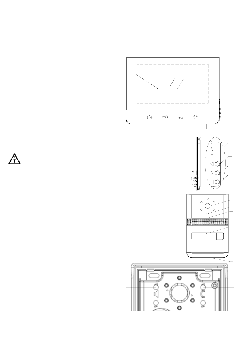
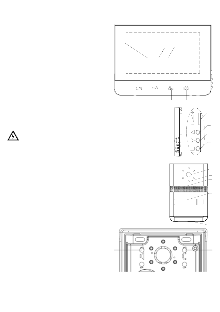
Inneneinheit (Abb. 1)
1. Bildschirm
2. Sprechen (antworten) ein/aus
3. Türönertaste
4. Kamera 1 (Überwachunsgmodus) /
opt. Kamera 2
5. Torönertaste
6. Mikrofone
7. Funktionsmenu
8. Hochschalten
9. Runterschalten
10. Klingeltonlautstärke
Außeneinheit
1. Kameralinse
2. IR-LEDs für Nachtsicht
3. Lautsprecher
4. Namensschild
5. Klingeltaste
6. Mikrofon
Fig. 3
A
A Linker Regler: Lautstärkeeinstellung des Lautsprechers
B Rechter Regler Lautstärkeeinstellung des
2
der Außeneinheit
Monitorlautsprechers
Fig. 2
10
9
8
7
1
2
3
4
5
6
B
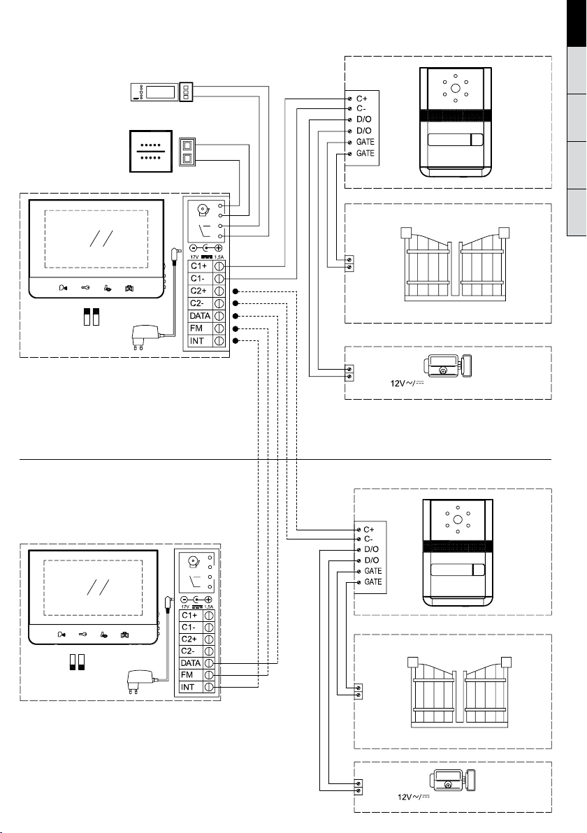
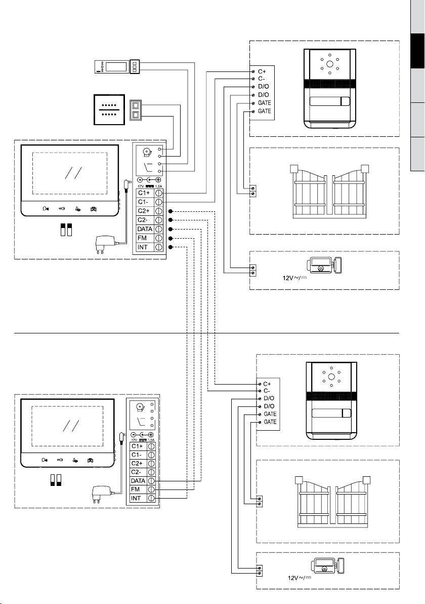
Montageanleitung
Schaltplan – 1. Familiensystem mit einer Ausseneinheit und
einer Inneneinheit
External doorbell / Externe Klingel
Electrical chime / Elektrischer Türgong
Master
Montageanleitung
Schaltplan – 1. Familiensystem mit einer zweiten
Ausseneinheit und einer zweiten Inneneinheit
(max. Ausbaustufe)
DEGBFRITPL
Dry contact / Potentialfreier Kontakt
DOOR OPEN / TÜRÖFFNER
Slave
Dry contact / Potentialfreier Kontakt
DOOR OPEN / TÜRÖFFNER
Kabelverbindung
SOPHIA
SOPHIA
SOPHIA
SOPHIA
140 cm
150 cm
1. Verbinden Sie Außen- und Inneneinheit gemäß der
Beschreibung im Schaltplan.
2. Fügen Sie die Drähte mit Bedacht in die Anschlüsse – ggf.
unter Zuhilfenahme eines geeigneten Werkzeugs. Achten
Sie darauf, dass sich zwei abisolierte Drähte niemals
berühren.
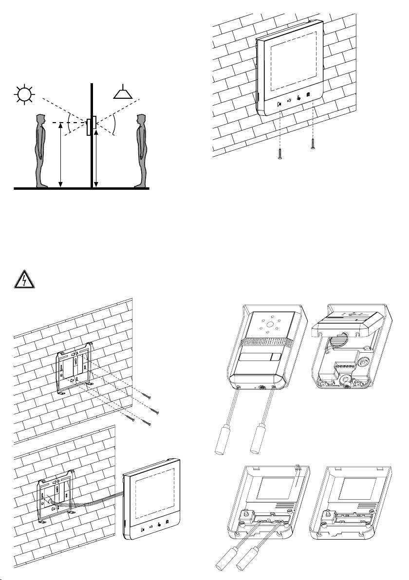
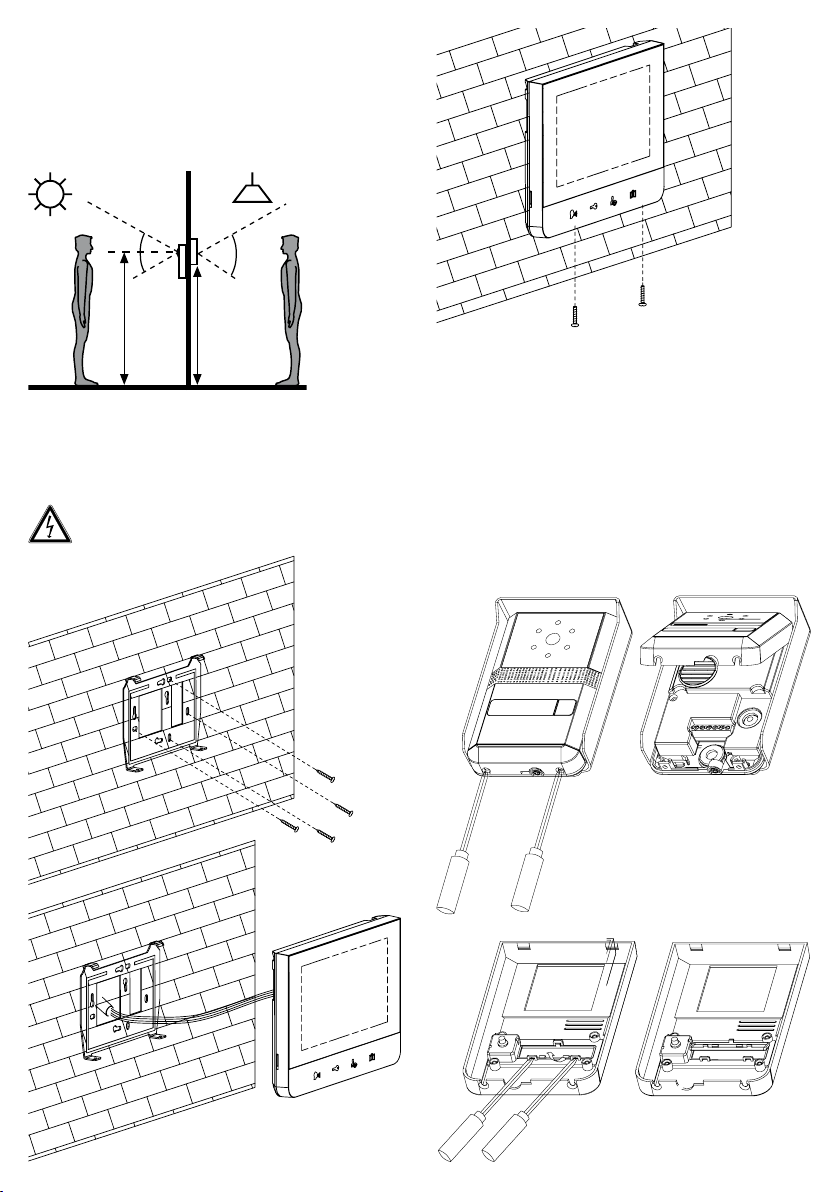
Installationshöhe
Die empfohlene Installationshöhe der Außeneinheit liegt bei
150-155 cm und bei 140 -150 cm bei der Inneneinheit.
40°
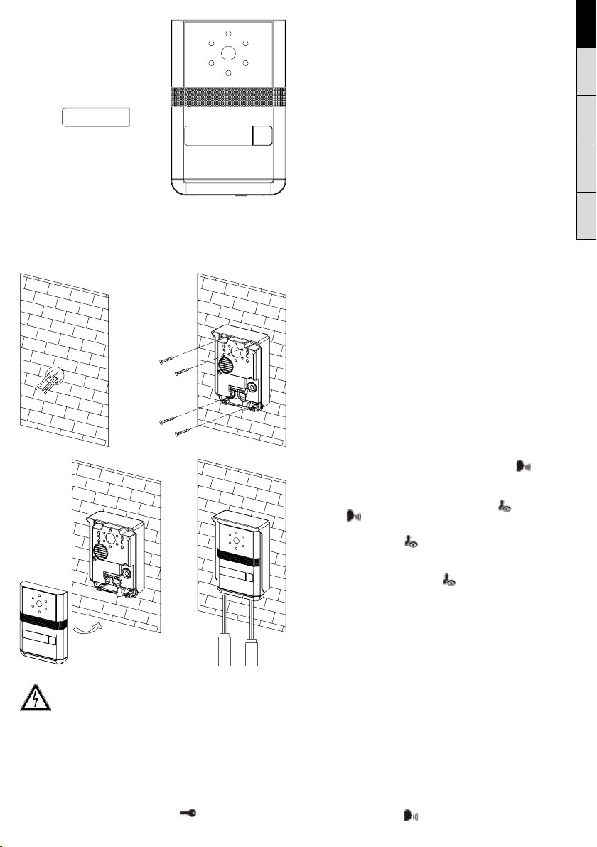
Installation der Inneneinheit
1. Suchen Sie sich eine geeignete Stelle in der Nähe einer
Steckdose. Lösen die die Wandhalterung aus dem Monitor,
indem Sie die beiden Schrauben auf der Unterseite entfernen.
Montieren Sie die Wandhalterung der Inneneinheit mit den
vier im Lieferumfang enthaltenen Schrauben und Dübeln an
einer geeigneten Stelle.
2. Drücken Sie den Monitor in die Wandhalterung.
3. Fixieren Sie die Wandhalterung mit der Inneneinheit,
indem Sie die beiden Schrauben auf der Unterseite wieder
eindrehen.
Stellen Sie die Stromversorgung des Systems erst
dann her, wenn Sie die Außeneinheit bereits mit der
Inneneinheit verdrahtet haben. Stellen Sie sicher, dass
alle Anschlüsse polrichtg sind!
70°
Installation/ Einstellung der Außeneinheit
Zwei Einstellungen können im Inneren der Außeneinheit
vorgenommen werden. Oben links können Sie die
Lautstärke des Lautsprechers der Außeneinheit justieren
(Abb. 3A), oben rechts die Lautstärke des Lautsprechers der
Inneneinheit (Abb. 3B).
Um die Einstellungen zu ändern, verwenden Sie z. B. einen
Schraubendreher und drehen ohne Kraft an den Reglern.
Beschriftung des Namensschilds
1. Entfernen Sie die Front mit einem Schraubendreher
(Abb. A/B).
2. Lösen Sie die Verankerung des Namensschilds vorsichtig
mit einem geeignetem Werkzeug (Abb. C/D).
3. Das Namensschild ist nun zugänglich (Abb E). Beschriften
Sie das Namensschild (Abb. E).
4. Führen Sie die Schritte in umgekehrter Reihenfolge aus um
das Namenschild wieder zu verankern und um das Gehäuse
zu schließen.
A B
C D
4
SOPHIA
F
E
SOPHIA
SOPHIA
Wandmontage der Außeneinheit
1 Montieren Sie die Außeneinheit mit vier Schrauben und
vier Dübeln an der dafür vorgesehen Stelle (Abb. H/I).
2 Entfernen Sie das Frontgehäuse der Außeneinheit, indem
Sie die beiden auf der Unterseite befindlichen Schrauben
lösen (Abb. J/K).
H I
J
Achten Sie darauf die Schrauben nicht in die Mikrofonönung
zu schrauben! Achten Sie bei der Montage darauf,
dass die Kamera zu keiner Tageszeit direkt in die
Sonne oder auf reflektierende Flächen gerichtet ist.
Kabelverbindung der Außeneinheit
Verbinden Sie die Inneneinheit(en) und die Außeneinheit(en)
und ggf. den optionalen Türöner wie im Schaltdiagramm
angegeben. Fügen Sie die Drähte in die Anschlüsse ein und
achten wieder darauf, dass sich keine abisolierten Kabelenden
berühren, auch nicht nach dem Anschluss!
(Optionale) Installation eines Türöners
Dieses Videotürsprechsystem bietet die Möglichkeit einen
Türöner zu steuern. Hierdurch können Sie ferngesteuert z.B.
eine Haustür önen, indem Sie den
Verdrahtung siehe Schaltplan).
Knopf drücken. (Zur
K
Achtung: Es ist essentiell, dass der elektrische Türöner,
den Sie verwenden, eine Memoryfunktion besitzt. Wir
empfehlen die Verwendung der Türöner GEV Bestell.Nr. 07680 oder GEV 07697.
(Optionale) Installation eines Hutschienennetzteils
anstelle eins Steckdosennetzteils
In dem Fall, das Sie in der Nähe der Inneneinheit keine
Steckdose haben, gibt es die Möglichkeit, das System
mithilfe eines Hutschienennetzteils mit Spannung zu
versorgen (nicht im Lieferumfang/ separat erhältlich).
GEV Bestell.-Nr. 08834402. Um das Hutschienennetzteil
zu verbinden folgen Sie den Artikel beiliegenden
Anweisungen).
(Optionale) Installation einer Etagenklingel und
eines elektrischen Türgongs
Sie können optional eines oder beides der genannten
Geräte einzeln oder gemeinsam installieren. Die
Option der Etagenklingel gibt Ihnen die Freiheit einen
zusätzlichen Klingelknopf an einer geeigneten Stelle zu
installieren, z.B. vor Hintereingängen, etc. Die Möglichkeit
der Einbindung eines zusätzlichen elektrischen Türgongs
bietet die Freiheit einen Signalgeber an einem weiteren
Ort Ihrer Wahl zu installieren, im Falle, dass die in der
Inneneinheit integrierten Signale nicht laut genug oder
zu weit weg von einem präferierten Ort (z. B. Garten,
Keller) sind.
Geräteeinstellungen
Sie können die Helligkeit, den Kontrast und die
Farbwiedergabe des Monitors einstellen. Drücken Sie
bei eingeschaltetem Monitor den Menü-Knopf (Abb. 1/
Punkt 7) am rechten Rand der Inneneinheit.
Durchlaufend nach jedem Druck erscheinen die
Untermenüs. In dem Untermenü Ihrer Wahl nehmen
Sie die Einstellung durch Drücken der Hoch/ Runter
Tasten vor. Drücken Sie zum Bestätigen Ihrer Einstellung
nochmals den Menü-Knopf. Bitte drücken Sie die
Sensortasten mit Bedacht.
Bedienungsanweisungen
1. Eingehender Ruf
Wenn der Klingelknopf der Außeneinheit gedrückt
wurde, signalisiert die Inneneinheit einen eingehenden
Ruf und der Monitor schaltet sich ein. Nachdem
Sie den Besucher identifiziert haben und ggf. mit
Ihm sprechen möchten, drücken Sie die
Der Monitor bleibt ca. 60 s. in Betrieb bevor er sich
automatisch in den Stand-By schaltet. Um den
Monitor wieder aktiv in Betrieb zu nehmen um ggf.
weiter zu sprechen, drücken Sie die
dann
2. Überwachungsfunktion
3. Bereitschaftszeit
4. Interkom-Funktion
Taste.
a) Drücken Sie die
Kamera der Außeneinheit wird aktiviert.
b) Falls Sie zwei Außeneinheiten angeschlossen
haben, benutzen Sie die
beiden Kameras zu wechseln.
Falls Sie keine zwei Außeneinheiten verbunden haben
und dennoch versehentlich im Überwachungsbetrieb
diese Taste berühren, erhalten Sie einen Black Screen
und einen Warnton. Nach ca. 1 s. erscheint wieder
das Bild der angeschlossenen Kamera.
a) Sprechzeit: Ca. 30 s. . Das Bild schaltet sich
automatisch ab, falls keine Reaktion auf den Ruf
erfolgt.
b) Gesprächszeit: Ca, 60 s. wenn der eingehende Ruf
beantwortet wird. Danach schaltet der Monitor
automatisch ab.
c) Monitor-Zeit (Überwachungsmodus): Ca. 30 s.
wenn die Außeneinheit durch die Inneneinheit
aktiviert wird. Danach schaltet das System wieder
in den Stand-By.
Inneneinheiten): Ein Gespräch zwischen zwei
Taste der Inneneinheit und die
Taste, um zwischen
(bei Betrieb mit zwei
Taste.
Taste und
DEGBFRITPL
Inneneinheiten kann gestartet werden, indem von einer
Inneneinheit aus im Stand-By-Betrieb die
gedrückt wird. Daraufhin klingelt die zweite Inneneinheit.
Der Ruf kann angenommen werden durch Druck auf die
Taste des angerufenen Terminals. Drücken Sie noch
einmal die
Die Gesprächsdauer ist etwa 60 s. Danach schalten die
Einheiten wieder in den Stand-By Betrieb.
5. Aktivierung eines optionalen Türöners.
Falls ein Türöner in das System integriert ist, drücken
Sie die
aktivieren. Diese Funktion kann nur verwendet werden,
wenn der Monitor in Funktion ist. Es ist normal, daß
der Monitor sich kurz nach Betätigung in den Stand-By
Modus schaltet.
Wichtig: Es ist essentiell, dass der zu verwendende
Türöner über eine Memoryfunktion verfügt.
6. Aktivierung eines optionale Toröners.
Verbinden Sie die den Anschluss des Toröners direkt von
der Außeneinheit mit z. B. einem Torönermechanismus.
Dieser Kontakt ist potentialfrei. Drücken Sie
Torönermechanismus zu aktivieren.
7. Melodien
Um die Melodie zu wählen oder zu wechseln drücken
Sie im Stand-By Betrieb die
die aktuelle Melodie. Drücken Sie rasch die
durch die möglichen Melodien zu hören/ wählen. Es gibt
insgesamt vier Melodien zur Auswahl.Um Ihre Auswahl zu
bestätigen drücken Sie die
8. Nachtmodus/ Mute on/ o
Drücken Sie im Stand-By Modus der Inneneinheit die
Taste. Das Piktogramm wechselt die Farbe von Blau zu
Rot. Das Gerät befindet sich im Nachtmodus/ Lautlos
Modus. Es gibt keine akustischen Signalisierungen, wobei
die restlichen Funktionen weiterhin uneingeschränkt
nutzbar sind. Um den Nachtmodus zu beenden drücken
Sie erneut die
von Rot zu Blau zurück.
Ausbau/ Konfigurierung des Systems
Dieses System kann auf verschiedenen Ebenen
ausgebaut werden, z. B. durch Einbindung einer weiteren
Innen- und/ oder Außeneinheit. Bitte tun Sie dies unter
Beachtung der Anleitung im Schaltplan. Bitte Beachten
Sie ggf. die dazu ebenfalls nötigen Jumper-Einstellungen.
Wartung und Pflege
• Verwenden Sie die Geräte nicht ober oder unterhalb der
angebenen Werte (z. B. bzgl. der Temperaturen).
• Temperatureinflüsse können zu Fehlfunktionen oder
Defekten führen.
• Lassen Sie keine Komponente fallen oder setzen diesen
Stöße aus.
• Verwenden Sie zur Reinigung keine scharfen
Reinigungsmittel. Gelegentliches Abwischen mit einem
angefeuchtetem Tuch ist in der Regel ausreichend.
Taste, um das Gespräch zu beenden.
Taste, um den Türönermechanismus zu
Taste. Daraufhin erklingt
Taste.
Taste und das Piktogramm wechselt
Taste
Taste
Taste
um den
Taste um
Recycling Hinweise
Dieses Gerät darf nicht mit dem unsortierten Hausmüll
entsorgt werden. Besitzer von Altgeräten sind
gesetzlich dazu verpflichtet dieses Gerät fachgerecht
zu entsorgen. Informationen erhalten Sie von Ihrer
Stadt- bzw. Gemeindeverwaltung.
6

Häufige Fragestellungen – Praktische Hinweise
Problem Mögliche Lösung
Kein Strom (kein Bild auf dem Monitor) • Ist die Stromversorgung richtig angeschlossen?
Spannung ist vorhanden, aber trotzdem
kein Bild auf dem Monitor
• Ist das Kabel zwischen Außen- und Inneneinheit richtig verbunden?
• Ist die Polarität der Drähte zwischen Außen-/ und Inneneinheit korrekt?
Das Bild ist zu dunkel • Ändern Sie die Helligkeitseinstellungen
Klingelton ist zu leise/ nicht zu hören • Prüfen Sie, ob eventuell der Nachtmodus aktiviert wurde
Hörlautstärke der Ausseneinheit zu
gering
Hörlautstärke der Inneneinheit zu
gering
• Abb. 3A linker Regler. Erhöhen Sie die Lautstärke des Lautsprechers
• 3B rechter Regler. Erhöhen Sie die Lautstärke des Lautsprechers
Technische Daten
Inneneinheit Spezifikationen
Maße B 200 mm x H 145 mm x T 23 mm
Gewicht 0.5 Kg
Input Power DC17 V (via Netzadapter)
Stromverbrauch Stand-By max.: 2 W, Betrieb: Max. 14 W
Ruftöne 4
Max. Entfernung und Innneinheit zu Außeneinheit, 50 m: 1.0 mm
Kabeldurchmesser
Display 7 Inch Digital wide screen LCD (LED Backlight)
Inneneinheit A zu B 20 m: 1.5 mm2 Draht, Türöner zur Außeneinheit 20 m: 1.5 mm2 Draht
2
Draht, 100 m: 1.5 mm2 Draht,
Auflösung 1440 H x 234 V
zul. Betriebstemperatur 0 ~ 40°
Außeneinheit Spezifikationen
Maße B 95 mm x H 140 mm x T 43 mm
Gewicht 0.5 Kg (mit Regenschutzgehäuse)
Eingangsspannung DC12 V via Inneneinheit
Stromverbrauch Max. 3 W
Gehäusematerial Zinklegierung
Bildsensor 1/3“ Colour Sony Super HAD CCD Camera
Video output Composite video signal 1 Vp-p at 75 Ohm
Pixel 290.000 pixels
Beleuchtung IR-LED
Sichtwinkel Diagonal 90 Grad, horizontal 57,8 Grad, vertikal 48,6 Grad
Elektrischer Türöneranschluss DC 12V/ max. 1 A
Installationsart Wandmontage
Zulässige Umgebungstemperatur -10˚C ~ 50˚C
DEGBFRITPL
Technische und optische Änderungen ohne Ankündigung vorbehalten.
Single-dwelling building video door intercom
7
8
9
10
SOPHIA 88665
Safety & Operating Instructions
These instructions are for your safety. Please read through
them thoroughly before use and retain for future reference.
We recommend this equipment is installed by a competent
electrician.
Parts Supplied
Description Qty
Indoor Monitor 1
Outdoor Camera 1
Wall mounting bracket 1
Power Adaptor 1
Fittings Supplied
Description Qty
Screw 8
Wall plug 8
Wrench 1
Adapter Cables 1
Before You Start
• Check the accessory and make sure you have all of the
parts listed above included. If not, contact your local store
or your vendor for assistance.
• This video door phone set is composed of a monitor
with its power adaptor and an outdoor unit. t. It allows
communicating with the visitor who calls at the door
and controlling the opening of the door and/or gate. You
can develop your own installation by adding an optional/
additional monitor(s) and/or a second outdoor unit. For
a safe installation and use,
please read carefully these
instructions and keep them safe.
Safety Instructions
All warranty claims will be null and void in the event of any
damage or loss causedby failure to observe these operating
instructions. We accept no liability for any consequential
losses or damage. We accept no liability for any personal
injury or material damage caused by improper use or by
failure to observe the safety advice. In these cases the
guarantee and warranty are invalidated. For safety and
authorization purposes it is not permitted to carry out any
adaptation or conversion of the device.
1. Do not install near other electronic equipment such as
computers, TV, video recorder as this may cause radiated
interference to the unit.
2. Do not disassemble the unit.
3. Do not spray water on the indoor unit. Do not keep the
outdoor unit where it will be exposed to extreme
moisture.
4. Do not overload mains wall outlets or extension cords.
5. Do not drop or shock the unit.
6. Remove the power cord from the wall socket when unit is
not used for long periods.
7. Do not place any naked flames (e. g. lighted candles) on
the apparatus.
8. Do not place objects filled with water (e. g. vases) on the
apparatus.
9. Do not cover the ventilation holes with clothing, paper,
curtains etc.
10. This apparatus is designed for moderate climates. Do not
use in high humidity, dusty or dirty areas.
11. To disconnect or isolate the unit, switch o at the socket
or remove plug from wall socket. Please ensure the plug
and socket is easily accessible.
Warnings
1. Do not install the outdoor unit where it will be exposed
to direct sunlight or any strong reflected light. Avoid
extremely bright locations for the indoor unit as the
monitor screen image will be adversely aected.
2. Do not install the outdoor unit where it will be subjected
to extremes of dust or moisture.
3. Do not install the outdoor unit where it will be exposed
to rain.
4. Do not install near acid oxides, ammonia, or any harmful
gas (it might cause malfunction).
5. Do not install the outdoor unit in a location where the
lens filter is likely to get scratched or very dusty.
6. Check cables are connected correctly and camera unit
is firmly installed.
Indoor unit (Fig. 1)
1
23456
1. Monitor screen
2. Talk on/Talk o
(Monitor o)
3. Door lock Open
4. Camera 1 / Camera 2
(Surveillance Mode)
5. Gate Open Button
6. Microphone
7. Menu Select
(Brightness, Contrast, Colour)
8. Down
9. Up
10. Ring Sound volume
Outoor unit
1. Camera lens
2. IR-LEDs
for night vision
3. Speaker
4. Name Plate
5. Call Button
6. Microphone
Fig. 3
A
Fig. 2
A left knob - adjust sound level of the outdoor unit's speaker.
B right knob - adjust sound level of the speaker's monitor.
8
10
9
8
7
1
2
3
4
5
6
B
Assembly instructions
Wiring diagram – One-family system
with one outdoor and one indoor unit.
External doorbell / Externe Klingel
Electrical chime / Elektrischer Türgong
Master
DEGBFRITPL
Dry contact / Potentialfreier Kontakt
DOOR OPEN / TÜRÖFFNER
Wiring diagram – One-family system
with two outdoor and two indoor units.
(maximum extention stage)
Slave
Dry contact / Potentialfreier Kontakt
DOOR OPEN / TÜRÖFFNER
Cable connection
SOPHIA
SOPHIA
SOPHIA
SOPHIA
140 cm
150 cm
1. Connect the monitor to the camera with the cables
according to the wiring diagram.
2. Carefully insert the wires to the terminal by pressing
down the terminal flap with any small tool taking care that
the 2 bare wires do not touch.
Installation height
Recommended installation height is approximately 140 –
150 cm for indoor unit and 150 – 155 cm for outdoor unit.
40°
Installation of the indoor monitor
1. Fix the wall mounting bracket at the wall by using 4
screws and plugs.
2. Carefully place the indoor monitor against the bracket
and gently push down the monitor so that the pins on the
bracket engage in the slots on the rear of the monitor.
3. Secure the assembly with the 2 screws.
Only after having connected the outdoor unit,
connect the 230 V~ power supply to the adaptor.
Make sure the power supply polarity is correct.
70°
Installation of the outdoor unit
Two settings are accessible inside the outdoor unit:
On the upper left side, setting of the sound level for the
speaker of the outdoor unit. (fig. 3A)
On the upper right side, setting of the sound level for the
speaker of the monitor. (fig. 3B)
To change the settings, use a small screwdriver and turn it
carefully without force to the abutments.
Add the name to the nameplate
1. Remove the front cover with a screwdriver (fig. A-B)
2. Remove the holder of the name plate with a small
screwdriver. (fig. C-D )
3. The name plate is now accessible (fig. E)
4. Mark your name on the plate (fig. E)
5. Place the name plate holder back to the panel (fig. F)
A B
10
C D

SOPHIA
F
E
SOPHIA
SOPHIA
Mounting the outdoor unit
1) Mount the outdoor unit on the wall by using four mounting
screws and wall plugs. (fig. H-I)
2) Replace the front cover and security it by replacing the 2
screws at the bottom of the camera. (fig. J-K)
H I
J
Do not put screws into the microphone hole. Do
not point the video camera directly at the sun or at
reflecting surfaces.
Tip: we recommend passing the cables through a protective
sleeve to shield them from impacts and weather influences.
Cable connection
Connect the monitor(s) to the outdoor unit(s) and the
(optional) door opener with the cables according to the
wiring diagram. Carefully insert the wires to the terminals
with any small tool taking care that two bare wires do not
touch. Make absolutely sure that no bare wires are touching
each other after the connection!
(Optional) installation of a door opener
This video doorbell features the option to implement an
K
electrical door opener. This allows you to remotely open
a door by pressing the
to the diagrams.
Important: it is essential that the electric latch or lock
installed has a mechanical memory. We therefore
recommend GEV's door opener order no. 07680 or
order no. 07697
(Optional) installation of a DIN rail transformer
instead of a power adaptor
In case you haven't a power socket close enough
near by the indoor unit or you have the opportunity to
connect with your house installation, there's the option
to replace supplied power adaptor by a DIN rail-adaptor
(not included / separately available GEV order. no.
08834402). For installing the DIN-rail adaptor follow the
instructions that come along with it.
(Optional) installation of a floor bell and/or an
electronical door chime
This unit features several options of adding accessories
like an additional door chime or an extra call button (floor
bell).
You can either install individually one of the above
mentioned accessories or both at the same time.
The floor bell button connection option gives you the
freedom of choice to place an additional doorbell button
wherever you want. E. g. directly in front of your door or,
at a back entrance, etc..
The option for adding an electronical door chime
(speaker) allows you to place an external door (chime
besides the one built in the indoor unit. In case the built
in indoors unit's door chime is not loud enough or too far
away you can add an electronical door chime and freely
place it wherever required.
Connect the accecssory according to the wiring diagram.
Performance Settings
You can adjust the brightness, contrast and colour of the
monitor when it is ON by pressing the Menu button (fig.
1) at the side of the monitor.
Press the Menu button- then the brightness, contrast and
colour indication will appear. Select the setting you want
to adjust by pressing the Up and Down buttons, then
press the Menu button again to confirm the selection
and then press the Up and Down buttons to adjust.
Finally, press the Menu button to confirm the setting.
Operating Instructions
The touch keys must be handled by slightly touching
with the fingers.
1. Incoming call
When the call button on the outside camera unit is
pressed, the indoor unit chime rings and the visitor's
picture will appear on the indoor monitor. After the
visitor is visually identified, and you wish to talk with
the visitor, touch the
activated for approximately 60 seconds before it
automatically shuts o. To re-activate for continued
conversation, touch the
button.
2. Activation of outside unit from monitor unit
(Surveillance Mode)
a) Touch the
and the outdoor camera will be activated and
show the external view.
b) If you have installed two cameras, touch this
button to change from camera one to another.
If you press twice the button
not connected, you have a black screen and a noisy
sound. After 1 second the video of the main camera
reappears.
3. Operating time
a) Call time: Approximately 30 seconds.
The picture terminates automatically if indoor unit
is not answered within approximately 30 seconds
after the call button of the outdoor camera unit is
touched.
b) Talk time: Approximately 60 seconds
When monitor unit is called by the outdoor unit and
the monitor is answered, there is approximately 60
seconds of time available before the unit
button. For wiring please refer
button. The unit will remain
button and then touch the
button of the indoor unit at any time
that the camera is
DEGBFRITPL

automatically shuts o.
c) Monitor time: Approximately 30 seconds
When outside camera is activated from the inside,
there is approximately 30 seconds of viewing time
before the unit automatically shuts o.
4. Activation of “Intercom” button
An intercom calling can be started by any indoor monitor
when it is on standby mode.
When the intercom button
touched, this will ring all monitors in a system. You can
talk with the calling monitor by touching the
on the second monitor. Touch
There is approximately 60 seconds of time before the unit
automatically shuts o.
5. Activation of
Door open:
If an electrical lock or door strike is added to the
installation, connect it to the terminals at the back of the
roadside panel.
If you want to open the door to let the caller in, just touch
the
This function can only be used when the screen is
switched on. It is normal that the image switches o one
moment following the control of the door open.
Important: It is essential that the electric latch or lock
installed has a mechanical memory.
6. Activation of
Gate open:
Connect the gate opener directly to the terminals at the
back of the roadside panel which supplies a current-free
“dry” contact to connect to the “push button” control of
your automatic gate opener.
If you want to open the gate to let the caller in, just touch
the
This function can only be used when the screen is
switched on. It is normal that
the image switches o one moment following the control
of the gate opener.
7. Change the melody
At standby mode, touch the
melody. Then touch
There are 4 melodies available. To confirm the melody of
your choice, touch
8. Mute on/Mute o / Night Modus / Silent Modus
At standby mode,touch the
shifts from blue to red. When the monitor's status is
Mute on, there will be no melody, while other functions
will be normal. To reactivate the ring tone, touch
button,the pictogram
Extending your system/ Cofiguring your system
Thisy system can be extendend in several ways- e. g.
by adding more indoor or outdoor units. Please refer to
the wiring diagrams for installation. Please take not of
the jumper settings in the wiring diagrams. It is essential
that you adopt the Jumper settings according to the
information in the diagrams.
The jumpers are to be found on the backside of the indoor
unit and are marked with the letters M (Master) and S
(Slave). Both Jumper up mean Master unit, both jumpers
down mean slave unit.
Care and Maintenance
• Do not store in hot or cold areas. Extreme hot or cold
temperatures can shorten the life of electronic devices and
can distort/melt certain plastics or may cause malfunction.
• Dropping can result in failure to operate. Circuit boards
can crack and may not survive the impact.
• Do not use or store in areas of high levels of dirt or dust.
The electronics may be contaminated. Any moving parts
will wear prematurely.
• Do not use harsh chemicals, cleaning solvents or strong
detergents. To clean, wipe with a damp cloth from time to
time.
button
button on the indoor monitor.
button
button on the indoor monitor.
to choose your desired melody.
button again.
on either indoor monitor is
for shutting of again.
button, you can hear the
button, the pictogram
shifts from red to blue.
button
Recycling Instructions
Waste electrical products should not be disposed of
with household waste. Please recycle where facilities
exist. Check with your Local Authority or retailer for
recycling advice.
12

Troubleshooting – Practical tips
Problem Possible Solution
No power (no picture on monitor) • Is the AC plug firmly inserted into the AC outlet?
Power is on, but no image on the
monitor
• Is the cable firmly connected between the monitor and the camera?
• Is the polarity of wires correct between the outdoor unit and indoor
monitor unit?
The picture is too dark or too white • Adjust brightness control
Chime sound is too low • Adjust the volume control
Outdoor unit's speaker sound level
too loud/ silent
Sound level of the monitor's
speaker is to low
• Fig. 3A: left knob: adjust sound level of the outdoor unit's speaker.
• Fig. 3B: right knob: adjust sound level of the speaker's monitor.
Technical data
Indoor Unit Specifications
Dimensions W 200 mm x H 145 mm x D 23 mm
Weight 0.5 Kg
Input Power DC17 V (External Power Supply)
Power Consumption Idle mode: 2 W, Operating: Max. 14 W
Connecting System 2 wires, 2 cameras, 2 monitors
Call sound Chime sound
Max. Distance & wiring Monitor to camera, 50 m: 1.0 mm
Master to slave 20 m: 1.5 mm
2
wire, 100 m: 1.5 mm2 wire,
2
wire, Door lock to camera 20 m: 1.5 mm2 wire
Display 7 Inch Digital wide screen LCD (LED Backlight)
Resolution 1440 H x 234 V
Operating Temperature 0 ~ 40°
Outoor Unit Specifications
Dimensions W 95 mm x H 140 mm x D 43 mm
Weight 0.5 Kg (w/rain shield)
Input Power DC12 V from monitor
Power Consumption Max. 3 W
Aspect Material Zinc alloy die casting with painting finish
Wiring Monitor: 2 wires, door lock: 2 wires
Image sensor 1/3“ Colour Sony Super HAD CCD Camera
Resolution 420 TV Lines
Video output Composite video signal 1 Vp-p at 75 Ohm terminated
Pixels 290.000 pixels
Iris Electronic auto iris
Lighting IR-LED
Viewing Angle Diagonal: 90˚ horizontal: 57.8˚ vertical: 48.6˚
Lens 3.7 mm flat pin hole lens
Door lock 2 terminals with DC power output 12 V/max. 1 A
Mounting type Surface mount
Operating Temperature -10˚C ~ 50˚C
DEGBFRITPL
Technical and design features may be subject to change without notice.

Interphone portier vidéo pour maison individuelle
1
23456
7
8
9
10
SOPHIA88665
Consignes de sécurité et de fonctionnement
Ces instructions permettent de garantir votre sécurité.
Veuillez les lire attentivement avant l'utilisation et conservezles en vue d'une consultation ultérieure. L'installation de cet
appareil doit impérativement être eectuée par un spécialiste
expérimenté.
Contenu de la livraison
Description Nombre
Unité intérieure 1
Unité extérieure 1
Support mural 1
Boîtier de protection
contre les intempéries 1
Vis 8
Chevilles 8
Clé à vis 1
Câble d'adaptation 1
Avant de commencer
• Vérifiez le contenu et assurez-vous que toutes les pièces
mentionnées ci-dessus sont présentes. Si l'une des pièces
est manquante, contactez l'entreprise ou le vendeur auprès
duquel vous vous êtes procuré cet appareil.
• Ce kit comprend un moniteur (unité intérieure) avec le
bloc d'alimentation correspondant et une unité extérieure
(sonnette). Grâce à ce kit, il vous est possible de communiquer
avec un visiteur ayant actionné l'unité extérieure et de
commander à distance une gâche en option. Vous pouvez
personnaliser votre installation en intégrant au système une
deuxième unité extérieure ou intérieure.
Consignes de sécurité
Toutes les réclamations de garantie deviennent
caduques en cas de non-respect des instructions
énoncées dans le présent manuel. Nous déclinons toute
responsabilité quant aux éventuels dommages consécutifs.
Par ailleurs, nous ne pourrons être tenus pour responsables
des blessures corporelles imputables au non-respect des
consignes de sécurité ou à une utilisation non conforme du
produit. Dans de tels cas de figure, la garantie est annulée. Pour
des raisons de sécurité et de garantie, il est interdit d'eectuer
des modifications, sous quelque forme que ce soit, sur les
appareils.
1. Ne montez pas les composants à proximité d'autres
appareils électroniques tels qu'un ordinateur, un téléviseur,
un lecteur vidéo, etc.
2. Ne désassemblez en aucun cas les unités.
3. Tenez l'unité intérieure à l'abri de l'humidité ou de l'eau.
Évitez de placer l'unité extérieure dans des endroits
extrêmement humides.
4. N'exposez pas les appareils et le câble à des tensions
supérieures à la tension maximale spécifiée.
5. Ne faites pas tomber les composants et ne les exposez pas
à de fortes vibrations.
6. L'alimentation électrique doit obligatoirement être coupée
(fusible secteur déconnecté) pendant toute la durée de
l'installation. Débranchez l'appareil si vous n'avez pas
l'intention de l'utiliser pendant une longue durée.
7. N'exposez pas l'appareil aux flammes.
8. Ne posez jamais des récipients remplis de liquide sur l'unité
extérieure.
9. Ne recouvrez pas et n'obstruez pas les fentes d'aération.
10. Cet appareil a été conçu pour des températures modérées.
N'utilisez pas ce dispositif dans des zones présentant un
fort taux d'humidité ou à forte concentration de poussière.
11. Pour mettre le système hors tension, débranchez la fiche
électrique de la prise ou enlevez la fiche creuse de l'unité
intérieure. Assurez-vous que la prise secteur est facilement
accessible.
Avertissements
N'installez pas l'unité extérieure dans des endroits exposés
1.
à la lumière directe ou indirecte du soleil. En outre, lors du
choix de l'emplacement de l'unité intérieure, évitez les zones
très éclairées car cela diminue la visibilité du moniteur.
2. N'installez pas l'unité extérieure dans des environnements
présentant un taux d'humidité élevé.
3. Ne placez pas l'unité extérieure dans des endroits
susceptibles d'être exposés à une pluie battante.
4. N'utilisez jamais les composants dans des environnements
où ils peuvent entrer en contact avec des acides.
5. Veillez à ce que l'unité extérieure ne soit pas installée dans
des environnements où la surface de la caméra risque
d'être rayée (par ex. en raison de branches mobiles ou
d'emplacements étroits très fréquentés).
Unité intérieure (fig.1)
1. Écran
2. Activer/Désactiver la
fonction Parler (répondre)
3. Bouton de gâche
4. Caméra1 (mode Surveillance)/
Caméra2 en opt.
5. Bouton de gâche
6. Microphone
7. Menu de fonctions
8. Bouton Haut
9. Bouton Bas
10. Volume de sonnerie
Unité extérieure
1. Lentille de caméra
2. LED IR pour vision nocturne
3. Haut-parleur
4. Plaque de nom
5. Sonnette
6. Micro
Fig.3
A
A Bouton de réglage gauche: réglage du volume sonore du
B Bouton de réglage droit: réglage du volume sonore du
14
haut-parleur de l'unité extérieure
haut-parleur du moniteur
Fig.2
10
9
8
7
1
2
3
4
5
6
B

Instructions de montage
Schéma électrique – 1. Système familial constitué d'une
unité extérieure et d'une unité intérieure
External doorbell / Externe Klingel
Electrical chime / Elektrischer Türgong
Master
Instructions de montage
Schéma électrique – 1. Système familial doté d'une
deuxième unité extérieure et d'une deuxième unité
intérieure (nombre max. de configurations)
DEGBFRITPL
Dry contact / Potentialfreier Kontakt
DOOR OPEN / TÜRÖFFNER
Slave
Dry contact / Potentialfreier Kontakt
DOOR OPEN / TÜRÖFFNER

Raccordement par câble
SOPHIA
SOPHIA
SOPHIA
SOPHIA
140 cm
150 cm
1. Raccordez les unités extérieure et intérieure tel que décrit
dans le schéma électrique.
2. Insérez prudemment les fils dans les raccords; si besoin,
utilisez un outil approprié. Veillez à ce que deux fils
dénudés ne se touchent jamais.
Hauteur d'installation
La hauteur recommandée pour l'installation de l'unité
extérieure est de 150 à 155cm, celle de l'unité intérieure de
140 à 150cm.
40°
Installation de l'unité intérieure
1. Cherchez un emplacement adéquat près d'une prise
secteur. Détachez le support mural du moniteur en
dévissant les deux vis se trouvant sur la face inférieure.
À l'aide des quatre vis et chevilles incluses dans la
livraison, fixez le support mural de l'unité intérieure à un
emplacement approprié.
2. Glissez le moniteur dans le support mural.
3. Fixez le support mural à l'unité intérieure en revissant les
deux vis sur la face inférieure.
Ne mettez le système sous tension qu'une fois le
câblage entre l'unité extérieure et l'unité intérieure
terminé. Assurez-vous que la polarité de toutes les
connexions est correcte!
70°
Installation/Réglage de l'unité extérieure
Deux réglages peuvent être eectués au niveau de l'unité
extérieure. En haut, vous pouvez ajuster le volume du hautparleur de l'unité extérieure à gauche (fig.3A) et celui du
haut-parleur de l'unité intérieure à droite (fig.3B).
Pour modifier les réglages, utilisez par exemple un tournevis
et tournez les boutons de réglage sans exercer une force
importante.
Étiquetage de la plaque de nom
1. Retirez la face avant du boîtier à l'aide d'un tournevis
(fig.A/B).
2. Détachez prudemment l'ancrage de la plaque de nom à
l'aide d'un outil approprié (fig.C/D).
3. La plaque de nom est désormais accessible (fig. E).
Étiquetez la plaque de nom (fig.E).
4. Suivez ces étapes dans l'ordre inverse pour fixer de
nouveau la plaque de nom et refermer le boîtier.
A B
C D
16

SOPHIA
F
E
SOPHIA
SOPHIA
Montage mural de l'unité extérieure
1 À l'aide de quatre vis et de quatre chevilles, fixez l'unité
extérieure à l'emplacement prévu à cet eet (fig.H/I).
2 Retirez le boîtier avant de l'unité extérieure en dévissant
les deux vis se trouvant sur la face inférieure (fig.J/K).
H I
J
Veillez à ne pas visser les vis dans l'ouverture du microphone!
Lors du montage, veillez à ce que la caméra ne soit,
à aucun moment de la journée, directement exposée
au soleil ou orientée vers une surface réfléchissante.
Raccordement par câble de l'unité extérieure
Raccordez le(s) unité(s) intérieure(s) et le(s) unité(s)
extérieure(s) et, le cas échéant, la gâche en option tel
qu'indiqué sur le schéma de connexions. Insérez les fils
dans les raccords et veillez encore à ce que les extrémités
dénudées des câbles ne se touchent pas, même après le
raccordement!
Installation d'une gâche (en option)
Cet interphone portier vidéo ore la possibilité de
commander une gâche. Ainsi, vous pouvez par exemple
ouvrir une porte à distance en appuyant sur le bouton
K
.
(Pour le câblage, se référer au schéma électrique).
Attention : Il est essentiel que la gâche électrique
utilisée dispose d'une fonction mémoire. Nous vous
recommandons d'utiliser la gâche GEV portant le n° de
commande 07680 ou la gâche GEV07697.
Installation d'un bloc d'alimentation sur rail
à la place d'un bloc d'alimentation adaptateur
secteur (en option)
Dans le cas où vous ne disposez d'aucune prise secteur
à proximité de l'unité intérieure, il vous est possible
d'alimenter le système en tension à l'aide d'un bloc
d'alimentation sur rail (non inclus dans la livraison,
disponible séparément). GEV, n° de commande
08834402. Pour connecter le bloc d'alimentation sur rail,
suivez les instructions fournies avec l'article.
Installation d'une sonnette pour étage et d'un
carillon électrique (en option)
Vous pouvez, en option, installer l'un des appareils
susmentionnés ou les deux, séparément ou ensemble.
L'option d'une sonnette pour étage vous donne la
liberté d'installer un bouton de sonnette supplémentaire
à un emplacement approprié, par exemple devant
l'entrée arrière. La possibilité d'intégrer un autre carillon
électrique permet d'installer librement un émetteur
de signal à un autre endroit au choix, si les signaux
sonores intégrés à l'unité intérieure ne retentissent pas
susamment ou sont trop éloignés d'un emplacement
préféré (jardin, cave, etc.).
Réglages de l'appareil
Vous pouvez ajuster la luminosité, le contraste et le
rendu des couleurs du moniteur. Lorsque le moniteur est
allumé, appuyez sur le bouton de menu (fig.1/point7)
sur le bord droit de l'unité intérieure.
Les sous-menus s'achent après la pression du bouton
de menu. Dans le sous-menu de votre choix, eectuez le
réglage souhaité en appuyant sur les boutons Haut/Bas.
Pour confirmer votre réglage, appuyez de nouveau sur
le bouton de menu. Veuillez presser les touches tactiles
avec prudence.
Instructions de fonctionnement
1. Appel entrant
Lorsque le bouton de sonnette de l'unité extérieure
est actionné, l'unité intérieure signale un appel
entrant et le moniteur s'allume. Après avoir identifié
le visiteur, si vous souhaitez dialoguer avec lui,
appuyez sur le bouton
pendant environ 60 secondes avant de se mettre
automatiquement en veille. Pour sortir le moniteur de
veille afin de continuer la conversation si nécessaire,
appuyez sur le bouton
2. Fonction de surveillance
a) Appuyez sur le bouton
pour activer la caméra de l'unité extérieure.
b) Si vous avez raccordé deux unités extérieures,
utilisez le bouton
à une autre.
Si vous n'avez pas raccordé une deuxième unité
extérieure et que vous eeurez par inadvertance ce
bouton en mode de surveillance, l'écran s'ache
tout en noir et un signal sonore retentit. Après
environ 1seconde, l'image de la caméra connectée
s'ache de nouveau.
3. Durée de service
a) Autonomie de communication: Env. 30secondes.
L'écran s'éteint automatiquement s'il n'y a pas de
réaction à l'appel.
b) Autonomie en conversation: Env. 60secondes
en cas de réponse à l'appel entrant. Le moniteur
s'éteint automatiquement par la suite.
c) Temps d'achage du moniteur (mode de
surveillance): Env. 30secondes si l'unité extérieure
est activée par l'unité intérieure. Le système
bascule de nouveau en mode veille.
. Le moniteur reste allumé
, puis sur le bouton
de l'unité intérieure
pour passer d'une caméra
.
DEGBFRITPL

4. Fonction Intercom
intérieures): Une conversation peut être engagée entre
deux unités intérieures. Pour ce faire, appuyez sur le
bouton
veille. La deuxième unité intérieure sonne. L'appel peut
être pris en appuyant sur le bouton
appelé. Appuyez de nouveau sur le bouton
mettre fin à la conversation. La durée de la conversation
est d'environ 60secondes. Les unités passent ensuite en
mode veille.
5. Activation d'une gâche en option. Bouton
Dans le cas où une gâche est intégrée, appuyez sur le
bouton
ne peut être utilisée que lorsque le moniteur est en
marche. Il est normal que le moniteur passe brièvement
en mode veille après l'actionnement.
Important: Il est essentiel que la gâche utilisée dispose
d'une fonction mémoire.
6. Activation d'une gâche en option. Bouton
Connectez le raccordement pour gâche directement à
partir de l'unité extérieure à l'aide d'un mécanisme de
gâche par exemple. Ce contact est sec. Appuyez sur
pour activer le mécanisme de gâche.
7. Mélodies
Pour sélectionner ou changer la mélodie, appuyez sur le
bouton
mélodie actuelle résonne. Pressez rapidement le bouton
mélodies ou pour en sélectionner. Il existe environ quatre
mélodies au choix. Pour confirmer votre choix, appuyez
sur le bouton
8. Mode Nuit/Fonction Muet activée/désactivée
Lorsque l'unité intérieure est en mode veille, appuyez sur
le bouton
bleu au rouge. L'appareil est en mode Nuit/Silencieux.
Dans ce mode, aucun signal sonore ne retentit, les autres
fonctions marchent toutefois correctement. Pour quitter le
mode Nuit, appuyez de nouveau sur le bouton
pictogramme passe de nouveau du rouge au bleu.
Extension/Configuration du système
L'extension de ce système peut se faire à diérents
niveaux, à travers l'intégration d'une autre unité intérieure
ou extérieure par exemple. Il est impératif de le faire en
suivant les instructions du schéma électrique. Veuillez
également respecter les réglages des cavaliers (Jumper)
nécessaires, le cas échéant.
Maintenance et entretien
• N'utilisez pas les appareils à des valeurs inférieures ou
supérieures aux valeurs prescrites (pour les températures
par ex.).
• Les diérences de température peuvent causer des
dysfonctionnements ou des défauts.
• Ne faites pas tomber les composants, ne les exposez
pas à des impacts.
• Pour le nettoyage, n'utilisez pas des produits de
nettoyage agressifs. En général, l'emploi d'un chion
humide est susant.
pour sortir l'autre unité intérieure du mode
pour activer son mécanisme. Cette fonction
lorsque le dispositif est en état de veille. La
pour écouter, en les faisant défiler, les diérentes
(fonctionnement avec deux unités
du terminal
pour
.
. La couleur du pictogramme passe du
; le
Remarques concernant le recyclage
Cet appareil ne doit en aucun cas être jeté avec les
ordures ménagères. Les propriétaires d'équipements
électriques ou électroniques usagés ont en eet
l'obligation légale de les déposer dans un centre de
collecte sélective. Informez-vous auprès de votre
municipalité sur les possibilités de recyclage.
18

Foire aux questions – Conseils pratiques
Problème Solution possible
Pas de courant (aucune image sur le
moniteur)
Le moniteur est sous tension, mais
n'ache aucune image
• L'alimentation électrique est-elle correctement branchée?
• Le câble reliant l'unité extérieure à l'unité intérieure est-il correctement
connecté?
• La polarité des fils reliant les unités externe et interne est-elle correcte?
L'image est trop sombre • Ajustez les réglages de luminosité
La sonnerie est trop faible, impossible
de l'écouter
Volume d'écoute de l'unité extérieure
trop faible
Volume d'écoute de l'unité intérieure
trop faible
• Vérifiez si le mode Nuit a été activé
• Fig.3A, régulateur de gauche. Haussez le volume du haut-parleur
• 3B, régulateur de droite. Haussez le volume du haut-parleur
Caractéristiques techniques
Unité intérieure Spécifications
Dimensions L200mm x H145mm x P23mm
Poids 0,5Kg
Puissance d'entrée 17V cc (via adaptateur secteur)
Consommation électrique En veille max.: 2W, en marche: Max. 14W
Sonnerie 4
Distance max. et Entre unité intérieure et unité extérieure, 50m: fil 1,0mm
diamètre du câble entre unités intérieures A et B, 20m: fil 1,5mm2, entre gâche et unité extérieure
20m: fil 1,5mm
Écran Grand écran numérique LCD de 7pouces (rétroéclairage LED)
2
2
, 100m: fil 1,5mm2,
Résolution 1440H x 234V
Température de service adm. 0 ~ 40°
Unité extérieure Spécifications
Dimensions L95mm x H140mm x P43mm
Poids 0,5Kg (avec boîtier de protection contre les intempéries)
Tension d'entrée 12V cc via l'unité intérieure
Consommation électrique Max. 3W
Matériau du boîtier Alliage de zinc
Capteur d'images Caméra couleur CCD 1/3" Sony Super HAD
Sortie vidéo Signal vidéo composite 1Vp-p à 75Ohms
Nombre de pixels 290000pixels
Éclairage LED IR
Angle de vision 90° en diagonale, 57,8° à l'horizontal, 48,6° à la verticale
Raccordement pour gâche électrique 12V cc/max. 1A
Type d'installation Montage mural
Température ambiante admissible -10˚C ~ 50˚C
DEGBFRITPL
Des modifications techniques et esthétiques peuvent être apportées sans notification préalable.

Impianto di videocitofono monofamiliare
1
23456
7
8
9
10
SOPHIA 88665
Avvertenze di sicurezza e di funzionamento
Queste avvertenze sono per la sicurezza degli utenti.
Leggerle con attenzione prima di utilizzare il dispositivo
e conservarle al fine di poterle consultare all'occorrenza
in un secondo momento. Questo dispositivo deve essere
installato esclusivamente da una persona esperta.
Contenuto della confezione
Descrizione Quantità
Unità interna 1
Unità esterna 1
Supporto a parete 1
Alloggiamento antipioggia 1
Viti 8
Tasselli 8
Chiave per dadi 1
Cavo adattatore 1
Operazioni preliminari
• Verificare il contenuto e appurare se sono disponibili tutti
i componenti sopraindicati. In caso contrario, rivolgersi
al negozio o al rivenditore presso cui è stato acquistato
questo dispositivo.
• Questo set si compone di un monitor (unità interna) con
relativo alimentatore e un'unità esterna (campanello).
Questo set consente di comunicare con un visitatore che
attiva l'unità esterna e di controllare un apriporta opzionale
con comando a distanza. È possibile assemblare da sé la
propria installazione integrando nel sistema una seconda
unità aggiuntiva interna o esterna.
Avvertenze per la sicurezza
Tutte le richieste in garanzia diventano nulle se le indicazioni
di queste istruzioni non sono rispettate. Non ci
assumiamo alcuna responsabilità di eventuali
danni dovuti a inottemperanza. Non ci assumiamo
alcuna responsabilità di danni a persone riconducibili
all'inosservanza delle avvertenze di sicurezza oppure ad
un uso diverso da quello previsto. In questi casi la garanzia
decade. Per motivi associati alla sicurezza e alla garanzia
non è consentito eseguire modifiche di qualsiasi natura sui
dispositivi.
1. Montare i componenti in prossimità di altri apparecchi
elettronici, ad esempio computer, TV, dispositivi di
riproduzione video.
2. Non scomporre le unità.
3. Tenere l'unità interna lontano dall'umidità o dall'acqua.
Non collocare l'unità esterna in luoghi in cui viene
esposta a condizioni di umidità estrema.
4. Alimentare i dispositivi e i cavi soltanto alle tensioni
massime indicate.
5. Non far cadere i componenti e non esporli a forti
vibrazioni.
6. È consentito lavorare soltanto a tensione disattivata,
pertanto disinserire tassativamente il fusibile del circuito
di corrente. Estrarre la spina dalla presa qualora non
si voglia utilizzare intenzionalmente il dispositivo per
periodi prolungati.
7. Non esporre i dispositivi alle fiamme.
8. Non collocare alcun contenitore pieno di liquido sull'unità
esterna.
9. Non coprire né applicare del nastro adesivo sulle fessure
di aerazione.
10. Questo dispositivo è stato progettato per condizioni
climatiche moderate. Non utilizzare questo impianto in
aree molto umide oppure molto polverose.
11. Per scollegare il sistema dalla tensione di rete, estrarre
la spina di rete dalla presa oppure estrarre il connettore
della cavità dall'unità interna. Accertarsi che la presa di
rete sia facilmente accessibile.
Avvertenze di pericolo
1. Non installare l'unità esterna in luoghi in cui è esposta
alla luce solare diretta o indiretta. In egual misura,
evitare di scegliere ambienti eccessivamente luminosi
per l'installazione dell'unità interna, in quando la visibilità
del monitor sarà limitata.
2. Non installare l'unità esterna in ambienti molto umidi.
3. Non collocare l'unità esterna in luoghi in cui potrebbe
essere esposta alla pioggia battente.
4. Non assemblare i componenti in ambienti in cui
potrebbero entrare in contatto con acidi.
5. Prestare attenzione anché l'unità esterna non sia installata
in ambienti in cui il rivestimento della videocamera possa
subire gra (ad esempio, a causa di rami in movimento
oppure passaggi stretti molto frequentati).
Unità interna (Fig. 1)
1. Schermo
2. Conversazione (risposta) on/o
3. Tasto apriporta
4. Videocamera 1
(modalità sorveglianza)/
Videocamera 2 opz.
5. Tasto apriporta
6. Microfoni
7. Menu funzioni
8. Accensione
9. Spegnimento
10. Volume del campanello
Unità esterna
1. Obiettivo videocamera
2. LED IR per la visione
notturna
3. Altoparlante
4. Targhetta
5. Tasto del campanello
6. Microfono
Fig. 3
A
A Regolatore a sinistra: impostazione del volume
B Regolatore a destra: impostazione del volume
20
dell'altoparlante dell'unità esterna
dell'altoparlante del monitor
Fig. 2
10
9
8
7
1
2
3
4
5
6
B

Istruzioni di montaggio
Schema elettrico – Impianto monofamiliare con un'unità
esterna e un'unità interna
External doorbell / Externe Klingel
Electrical chime / Elektrischer Türgong
Master
Istruzioni di montaggio
Schema elettrico – Impianto monofamiliare con
una seconda unità esterna e una seconda unità
interna (livello di configurazione max.)
DEGBFRITPL
Dry contact / Potentialfreier Kontakt
DOOR OPEN / TÜRÖFFNER
Slave
Dry contact / Potentialfreier Kontakt
DOOR OPEN / TÜRÖFFNER

Collegamento cablato
SOPHIA
SOPHIA
SOPHIA
SOPHIA
140 cm
150 cm
1. Collegare l'unità esterna e l'unità interna attenendosi alla
descrizione nello schema elettrico.
2. Guidare con attenzione i fili nei collegamenti;
all'occorrenza impiegare un utensile idoneo come ausilio.
Fare attenzione anché due fili spelati non entrino mai in
contatto.
Altezza d'installazione
L'altezza d'installazione consigliata è di 150-155 cm per
l'unità esterna e di 140 -150 cm per l'unità interna.
40°
Installazione dell'unità interna
1. Cercare un punto idoneo in prossimità di una presa.
Staccare il supporto a parete dal monitor rimuovendo
entrambe le viti sul lato inferiore. Montare il supporto a
parete dell'unità interna in una posizione adatta con le
quattro viti e i tasselli compresi nella fornitura.
2. Premere il monitor nel supporto a parete.
3. Fissare il supporto a parete con l'unità interna serrando
nuovamente entrambe le viti sul lato inferiore.
Erogare l'alimentazione elettrica del sistema
soltanto quando l'unità esterna è già cablata con
l'unità interna. Accertarsi della corretta polarità dei
collegamenti!
70°
Installazione/Impostazione dell'unità esterna
È possibile configurare due impostazioni all'interno dell'unità
esterna. In alto a sinistra è possibile regolare il volume
dell'altoparlante dell'unità esterna (Fig. 3A), in alto a destra il
volume dell'altoparlante dell'unità interna (Fig. 3B).
Per modificare le impostazioni, utilizzare ad esempio un
cacciavite e ruotare i regolatori senza esercitare una forza
eccessiva.
Scritta sulla targhetta
1. Rimuovere la parte anteriore con un cacciavite
(Fig. A/B).
2. Prestando cautela, staccare l'ancoraggio della targhetta
con un utensile idoneo (Fig. C/D).
3. Ora la targhetta è accessibile (Fig. E). Scrivere sulla
targhetta (Fig. E).
4. Eseguire le fasi in sequenza inversa per fissare di nuovo la
targhetta e per chiudere l'alloggiamento.
A B
C D
22

SOPHIA
F
E
SOPHIA
SOPHIA
Montaggio a parete dell'unità esterna
1 Montare l'unità esterna con quattro viti e quattro tasselli
nel luogo predisposto (Fig. H/I).
2 Rimuovere l'alloggiamento anteriore dell'unità esterna
svitando entrambe le viti sul lato inferiore (Fig. J/K).
H I
J
Attenzione: non avvitare le viti nell'apertura del microfono!
Durante il montaggio, prestare attenzione anché la
videocamera non sia orientata, in nessun momento
della giornata, verso il sole oppure superfici riflettenti.
Collegamento cablato dell'unità esterna
Collegare la(e) unità interna(e) e la(e) unità esterna(e) e,
all'occorrenza, l'apriporta opzionale come indicato nello
schema elettrico. Guidare i fili nei collegamenti e prestare
sempre attenzione anché le estremità spelate dei cavi non
entrino a contatto, anche dopo il collegamento!
Installazione (opzionale) di un apriporta
Questo videocitofono ore l'opportunità di controllare un
apriporta. In questo modo, è possibile telecomandare, ad
esempio, l'apertura di una porta premendo il tasto
il cablaggio, vedere lo schema elettrico.)
K
. (Per
Attenzione: È fondamentale che l'apriporta elettrico
utilizzato abbia in dotazione una funzione memory.
Consigliamo di utilizzare l'apriporta con codice GEV
07680 oppure GEV 07697.
Installazione (opzionale) di un alimentatore su guida
DIN
al posto di un alimentatore su presa
Nel caso in cui non sia disponibile una presa vicino
all'unità interna, è possibile erogare tensione al
sistema per mezzo di un alimentatore su guida DIN
(non compreso nella fornitura/venduto separatamente).
Codice GEV 08834402. Per collegare l'alimentatore su
guida DIN, attenersi alle istruzioni allegate all'articolo.
Installazione (opzionale) di un campanello per piano
e un gong elettrico
È possibile installare uno o entrambi i dispositivi
sopraindicati insieme o separatamente. L'opzione
del campanello per piano ore all'utente la libertà di
installare un campanello aggiuntivo in un luogo idoneo,
ad esempio, in prossimità di ingressi sul retro ecc. La
possibilità di collegare un gong elettrico aggiuntivo
ore la libertà di installare un segnalatore in un altro
luogo di propria scelta nel caso in cui i segnali integrati
nell'unità interna non siano di un volume suciente o
semplicemente troppo distanti dal luogo preferito (ad
esempio, in giardino o in cantina).
Impostazioni del dispositivo
È possibile regolare la luminosità, il contrasto e la resa
dei colori del monitor. Con il monitor acceso, premere
il tasto del menu (Fig. 1/punto 7) sul margine destro
dell'unità interna.
Premendo costantemente sarà possibile visualizzare
i sottomenu. Nel sottomenu di propria scelta,
configurare l'impostazione premendo i tasti su/giù.
Premere nuovamente il tasto del menu per confermare
l'impostazione prescelta. Premere con cautela i tasti dei
sensori.
Istruzioni per l'uso
1. Chiamata in entrata
Se si preme il tasto del campanello dell'unità esterna,
l'unità interna segnala una chiamata in entrata e il
monitor si accende. Dopo aver identificato il visitatore
e, all'occorrenza, aver parlato con lui, premere il
tasto
secondi prima di passare alla modalità di standby.
Per riattivare il monitor ed eventualmente continuare
a parlare, premere il tasto
2. Funzione di sorveglianza
a) Premere il tasto
b) Qualora siano state collegate due unità esterne,
Qualora non siano state collegate due unità esterne
e, tuttavia, si prema inavvertitamente questo tasto
in modalità di sorveglianza, sarà visualizzata una
schermata vuota e sarà emesso un segnale acustico.
Dopo circa 1 secondo sarà visualizzata nuovamente
l'immagine della videocamera collegata.
3. Tempo di predisposizione
a) Tempo di risposta: ca. 30 secondi. L'immagine
b) Durata della conversazione: ca. 60 secondi
c) Durata della visualizzazione sul monitor (modalità
4. Funzione di citofono
con due unità interne): è possibile avviare una
. Il monitor resta in funzione per circa 60
e poi il tasto
videocamera dell'unità esterna si attiva.
utilizzare il tasto
videocamera all'altra.
scompare automaticamente qualora non vi sia
alcuna reazione alla chiamata.
se si risponde alla chiamata in entrata.
Successivamente, il monitor si spegne.
di sorveglianza): ca. 30 secondi se l'unità esterna
viene attivata dall'unità interna. Successivamente,
il sistema torna di nuovo in modalità di standby.
dell'unità interna e la
per passare da una
(in caso di funzionamento
.
DEGBFRITPL

conversazione tra due unità interne premendo il tasto
per uscire dalla modalità in standby di un'unità interna.
Subito dopo squilla la seconda unità interna. La chiamata
può essere accettata premendo il tasto
chiamato. Premere di nuovo il tasto
conversazione. La durata della conversazione è di circa
60 secondi. Successivamente, le unità tornano di nuovo
in modalità di standby.
5. Attivazione di un apriporta opzionale. Tasto
Qualora nel sistema sia integrato un apriporta, premere il
tasto
funzione può essere impiegata esclusivamente se il
monitor è in funzione. È normale che il monitor passi alla
modalità di standby subito dopo l'attivazione.
Importante: è fondamentale che l'apriporta da utilizzare
disponga di una funzione memory.
6. Attivazione di un apriporta opzionale. Tasto
Collegare il collegamento dell'apriporta direttamente
dall'unità esterna, ad esempio, con un meccanismo
apriporta. Questo contatto è privo di potenziale. Premere
7. Melodie
Per selezionare o cambiare la melodia, premere il tasto
la melodia attuale. Premere velocemente il tasto
ascoltare/scegliere le melodie possibili. Sono disponibili
complessivamente quattro melodie. Per confermare la
propria scelta, premere il tasto
8. Modalità notturna/Mute on/o
In modalità di standby dell'unità interna, premere il tasto
dispositivo si trova in modalità notturna/silenziosa. Non
sono previste segnalazioni acustiche, quindi è possibile
continuare a utilizzare le funzioni restanti senza restrizioni.
Per terminare la modalità notturna, premere di nuovo il
tasto
Smontaggio/configurazione del sistema
Questo sistema può essere configurato a diversi livelli,
ad esempio, collegando un'unità interna e/o esterna
aggiuntiva. Eseguire quest'operazione ottemperando alle
istruzioni nello schema elettrico. All'occorrenza, prestare
attenzione alle impostazioni dei ponticelli necessari.
Cura e manutenzione
• Non utilizzare i dispositivi applicando valori superiori o
inferiori a quelli indicati (ad esempio, per quanto riguarda
le temperature).
• Gli influssi di temperatura possono portare a
malfunzionamenti o difetti.
• Non far cadere i componenti oppure non esporli a urti.
• Per la pulizia, non impiegare detergenti aggressivi. Di
norma, è suciente passare un panno inumidito secondo
necessità.
per attivare il meccanismo apriporta. Questa
per attivare il meccanismo apriporta.
in modalità di standby. Subito dopo viene emessa
. Il pittogramma cambia colore da azzurro a rosso. Il
e il pittogramma passerà da rosso ad azzurro.
del terminale
per terminare la
.
per
Istruzioni per il riciclaggio
Il presente dispositivo non deve essere smaltito
come rifiuto domestico indierenziato. I possessori di
dispositivi obsoleti sono tenuti a smaltire il dispositivo
come regolamentato delle normative vigenti. Per
ulteriori informazioni rivolgersi all'amministrazione
comunale.
24

Domande frequenti – Avvertimenti pratici
Problema Soluzione possibile
Assenza di corrente (nessuna immagine
sul monitor)
La tensione è presente, tuttavia non è
possibile visualizzare l'immagine sul
monitor
• La corrente elettrica è collegata correttamente?
• Il cavo tra l'unità esterna e l'unità interna è collegato correttamente?
• La polarità dei fili tra l'unità esterna e l'unità interna è corretta?
L'immagine è troppo scura • Modificare le impostazioni di regolazione della luminosità
L'avviso acustico è di un volume troppo
basso/è impercettibile
Il volume dell'unità esterna è troppo
basso
Il volume dell'unità interna è troppo
basso
• Verificare l'eventuale attivazione della modalità notturna
• Fig. 3A per il regolatore a sinistra. Aumentare il volume dell'altoparlante
• 3B per il regolatore a destra. Aumentare il volume dell'altoparlante
Dati tecnici
Unità interna Specifiche
Dimensioni L 200 mm x A 145 mm x P 23 mm
Peso 0,5 Kg
Alimentazione in ingresso 17 VCC (tramite adattatore di rete)
Consumo energetico Standby max.: 2 W, Funzionamento: max. 14 W
Suonerie 4
Distanza massima tra unità interna e unità esterna, 50 m: filo di 1,0 mm
Diametro del cavo Unità interna da A a B 20 m: filo di 1,5 mm
Display Display digitale da 7" LCD (retroilluminazione a LED)
2
, 100 m: filo di 1,5 mm2,
2
, da apriporta a unità esterna 20 m: filo di 1,5 mm
Risoluzione 1440 H x 234 V
Temperatura di esercizio consentita 0 ~ 40°
Unità esterna Specifiche
Dimensioni L 95 mm x A 140 mm x P 43 mm
Peso 0,5 Kg (con alloggiamento antipioggia)
Tensione in ingresso 12 VCC tramite unità interna
Consumo energetico Max. 3 W
Materiale dell'alloggiamento Lega di zinco
Sensore immagine Videocamera da 1/3” Colour Sony Super HAD CCD
Riproduzione video Segnale video composito 1 Vp-p a 75 Ohm
Pixel 290.000 pixel
Illuminazione LED IR
Angolo visuale In diagonale 90 gradi, in orizzontale 57,8 gradi, in verticale 48,6 gradi
Collegamento dell'apriporta elettrico 12 VCC/max. 1 A
Tipo d'installazione Montaggio a parete
Temperatura ambiente consentita -10 ˚C ~ 50 ˚C
DEGBFRITPL
2
L'azienda si riserva il diritto di apportare modifiche tecniche ed estetiche senza preavviso.

Wideodomofon do domu jednorodzinnego
1
23456
7
8
9
10
SOPHIA 88665
Wskazówki dotyczące użytkowania i bezpieczeństwa
Te wskazówki są dla Państwa bezpieczeństwa. Przed użyciem
urządzenia proszę uważnie je przeczytać i zachować do
wglądu na przyszłość. Instalację urządzenia powinien wykonać
wyłącznie wykwalifikowany specjalista.
Zestaw zawiera
Opis lość
Moduł wewnętrzny 1
Moduł zewnętrzny 1
Uchwyt ścienny 1
Obudowa przeciwdeszczowa 1
Śruby 8
Kołki 8
Klucz płaski 1
Przejściówka 1
Przed rozpoczęciem pracy
• Sprawdzić zawartość zestawu i upewnić się, że dostarczono
wszystkie w/w części. W przeciwnym razie skontaktować się
ze sklepem lub sprzedawcą, który sprzedał urządzenie.
• Zestaw składa się z monitora (moduł wewnętrzny) z
pasującym zasilaczem oraz modułu zewnętrznego (dzwonka).
Zestaw pozwala na komunikację z osobą, która włączy
moduł zewnętrzny oraz na zdalne sterowanie opcjonalnym
otwieraczem drzwi. Istnieje możliwość stworzenia własnej
instalacji, poprzez podłączenie do systemu drugiego
dodatkowego modułu zewnętrznego lub wewnętrznego.
Wskazówki bezpieczeństwa
W przypadku nieprzestrzegania zaleceń z niniejszej instrukcji
wszelkie roszczenia gwarancyjne tracą ważność. Nie ponosimy
odpowiedzialności za ewentualne szkody, które powstaną
na skutek nieprzestrzegania instrukcji obsługi. Nie
ponosimy odpowiedzialności za szkody osobowe, które
powstaną na skutek niestosowania się do wskazówek
bezpieczeństwa lub z powodu nieprawidłowego użytkowania.
W takich przypadkach gwarancja wygasa. Ze względów
bezpieczeństwa oraz dla zachowania gwarancji nie dopuszcza
się przeprowadzania jakichkolwiek zmian w urządzeniach.
1. Nie montować elementów w pobliżu innych urządzeń
elektronicznych np. komputerów, telewizorów, odtwarzaczy
wideo.
2. Nie wolno rozkładać modułów na części.
3. Chronić moduł wewnętrzny przed zawilgoceniem i
zmoczeniem. Nie umieszczać modułu zewnętrznego w
miejscach, w których byłby narażony na ekstremalne
zawilgocenie.
4. Urządzenia oraz przewody podłączać tylko do maks.
określonych napięć.
5. Nie dopuszczać do upadku elementów oraz nie narażać ich
na wysokie wibracje.
6. Prace mogą być wykonywane tylko w stanie bez napięcia,
w tym celu należy bezwzględnie wyłączyć bezpiecznik
w obwodzie elektrycznym. Jeżeli urządzenie nie będzie
używane przez dłuższy czas, należy wyciągnąć wtyczkę z
gniazdka.
7. Nie wystawiać urządzeń na działanie ognia.
8. Nie ustawiać na module zewnętrznym pojemników
napełnionych płynami.
9. Nie przykrywać ani nie zaklejać szczelin wentylacyjnych.
10. Urządzenie jest przeznaczone do użytku w klimacie
umiarkowanym. Nie stosować urządzenia na obszarach o
dużej wilgotności oraz wysokim stopniu zanieczyszczenia
pyłem.
11. Aby odłączyć system od napięcia sieciowego, wystarczy
wyciągnąć wtyczkę z gniazdka lub wyjąć wtyk rurkowy z
modułu wewnętrznego. Należy się upewnić, że gniazdko
zasilania jest łatwo dostępne.
Ostrzeżenia
1. Nie instalować modułu zewnętrznego w miejscu, gdzie będzie
narażony na bezpośrednie lub pośrednie działanie promieni
słonecznych. Przy wyborze miejsca montażu dla modułu
wewnętrznego należy unikać bardzo jasnego otoczenia, gdyż
może to ograniczyć widoczność na monitorze.
2. Nie instalować modułu zewnętrznego w miejscach o dużej
wilgotności.
3. Nie montować modułu zewnętrznego w miejscach, w których
byłby narażony na zacinający deszcz.
4. Nie używać urządzeń w otoczeniu, w którym mogłyby wejść
w kontakt z kwasami.
5. Uważać, aby nie zainstalować modułu zewnętrznego w
otoczeniu, w którym mogłoby dojść do porysowania pokrywy
kamery (np. przez poruszające się gałęzie lub na wąskiej
przestrzeni o dużym natężeniu ruchu).
Moduł wewnętrzny (rys. 1)
1. Ekran
2. Głos (odpowiedź) wł./wył.
3. Przycisk otwierania drzwi
4. Kamera 1 (tryb monitoringu)/
opcj. Kamera 2
5. Przycisk otwierania drzwi
6. Mikrofon
7. Menu funkcji
8. Zwiększanie
9. Zmniejszanie
10. Głośność dzwonka
Moduł zewnętrzny
1. Soczewka kamery
2. Diody LED na podczerwień
dla widzenia w ciemności
3. Głośnik
4. Tabliczka imienna
5. Przycisk dzwonka
6. Mikrofon
Ilustr. 3
A
A Lewe pokrętło: Regulacja głośności głośnika modułu
B Prawe pokrętło Regulacja głośności głośnika monitora
26
zewnętrznego
Ilustr. 2
10
9
8
7
1
2
3
4
5
6
B

Instrukcja montażu
Schemat połączeń – 1. System domowy z jednym modułem
zewnętrznym i jednym modułem wewnętrznym
External doorbell / Externe Klingel
Electrical chime / Elektrischer Türgong
Master
Instrukcja montażu
Schemat połączeń – 1. System domowy z drugim
modułem zewnętrznym oraz drugim modułem
wewnętrznym (maks. stopień rozbudowy)
DEGBFRITPL
Dry contact / Potentialfreier Kontakt
DOOR OPEN / TÜRÖFFNER
Slave
Dry contact / Potentialfreier Kontakt
DOOR OPEN / TÜRÖFFNER

Połączenie kablowe
SOPHIA
SOPHIA
SOPHIA
SOPHIA
140 cm
150 cm
1. Podłączyć moduł wewnętrzny i zewnętrzny zgodnie z
opisem na schemacie połączeń.
2. Wprowadzić dokładnie kable w otwory – w razie potrzeby
użyć odpowiedniego narzędzia. Uważać, aby nigdy
nie doszło do zetknięcia się dwóch niezaizolowanych
przewodów.
Wysokość montażu
Zalecamy wysokość montażu w przedziale 150–155 cm
dla modułu zewnętrznego oraz 140–150 cm dla modułu
wewnętrznego.
40°
Instalacja modułu wewnętrznego
1. Znaleźć odpowiednie miejsce w pobliżu gniazdka
elektrycznego. Zdjąć uchwyt ścienny z monitora, odkręcając
obie śruby na spodzie. Zamontować uchwyt ścienny
modułu wewnętrznego w odpowiednim miejscu za pomocą
czterech śrub i kołków dołączonych do zestawu.
2. Wcisnąć monitor w uchwyt ścienny.
3. Zamocować uchwyt ścienny wraz z modułem wewnętrznym,
przykręcając z powrotem obie śruby na spodzie.
Zasilanie można podłączyć dopiero wtedy, gdy zostaną już
podpięte wszystkie przewody modułu zewnętrznego i
wewnętrznego. Należy się upewnić, że wszystkie złącza
są przyporządkowane do odpowiednich biegunów!
70°
Instalacja/ustawianie modułu zewnętrznego
Dwa ustawienia można wykonać wewnątrz modułu
zewnętrznego. U góry po lewej stronie można wyregulować
głośność głośnika modułu zewnętrznego (rys. 3A), a u góry
po prawej stronie – głośność głośnika modułu wewnętrznego
(rys. 3B).
Do zmiany ustawień należy użyć, np. śrubokręta, i przekręcić
pokrętła, nieużywając siły.
Opisywanie tabliczki imiennej
1. Zdjąć pokrywę przednią za pomocą śrubokręta
(rys. A/B).
2. Używając odpowiedniego narzędzia, usunąć mocowanie
tabliczki imiennej (rys. C/D).
3. Tabliczka imienna jest teraz dostępna (rys. E). Opisać
tabliczkę imienną (rys. E).
4. Wykonać poszczególne etapy w odwrotnej kolejności,
aby z powrotem zamocować tabliczkę imienną i zamknąć
obudowę.
A B
C D
28

SOPHIA
F
E
SOPHIA
SOPHIA
Montaż na ścianie modułu zewnętrznego
1 Zamontować moduł zewnętrzny za pomocą czterech śrub
i czterech kołków w przewidzianym do tego celu miejscu
(rys. H/I).
2 Zdjąć przednią obudowę modułu zewnętrznego,
odkręcając śruby znajdujące się na spodzie (rys. J/K).
H I
J
Uważać, aby nie wkręcić śrub w otwór mikrofonu! Podczas
montażu uważać, aby kamera o żadnej porze dnia
nie była skierowana bezpośrednio w słońce lub na
powierzchnie odbijające światło.
Połączenie kablowe modułu zewnętrznego
Połączyć moduł(y) wewnętrzny(e) i zewnętrzny(e) oraz
ewentualnie opcjonalny otwieracz drzwi zgodnie ze
schematem połączeń. Włożyć przewody do złączy, uważając,
aby niezaizolowane końcówki kabla nie dotykały się, nawet po
podłączeniu!
(Opcjonalna) instalacja otwieracza drzwi
Ten system wideodomofonu oferuje możliwość sterowania
otwieraczem drzwi. Dzięki niemu można zdalnie otworzyć
drzwi, naciskając przycisk
schemat połączenia).
. (Połączenie kabli – patrz
K
Uwaga: Istotne jest, aby elektryczny mechanizm
otwierania drzwi był wyposażony w funkcję Memory.
Polecamy wybrać mechanizm otwierania drzwi o nr zam.
GEV 07680 lub GEV 07697.
(Opcjonalna) instalacja zasilacza na szynę DIN
zamiast zasilacza gniazdkowego
W przypadku gdy w pobliżu modułu zewnętrznego nie ma
dostępu do gniazdka elektrycznego, istnieje możliwość
podłączenia systemu do napięcia za pomocą zasilacza
na szynę DIN (brak w zestawie/ dostępny osobno). Nr
zam. GEV 08834402. Aby połączyć zasilacz na szynę DIN,
należy postępować zgodnie z instrukcjami dołączonymi
do artykułu.
(Opcjonalna) instalacja dzwonka na piętro oraz
elektrycznego gongu drzwiowego
Istnieje możliwość zainstalowania obu wymienionych
urządzeń razem lub oddzielnie. Opcja dzwonka na piętro
umożliwia instalację dodatkowego przycisku dzwonka w
wybranym miejscu, np. przy tylnych drzwiach wejściowych
itp. Możliwość podłączenia dodatkowego elektrycznego
gongu drzwiowego pozwala z kolei na zainstalowanie
generatora dźwięku w kolejnym dowolnie wybranym
miejscu w przypadku, gdy sygnały wydawane przez moduł
wewnętrzny są zbyt ciche lub odległość od preferowanej
lokalizacji (np. ogrodu, piwnicy) jest zbyt duża.
Konfiguracja urządzenia
Można dostosować jasność, kontrast i odwzorowanie
kolorów monitora. Przy włączonym monitorze nacisnąć
przycisk Menu (rys. 1/punkt 7) w prawym rogu modułu
wewnętrznego.
Po każdym naciśnięciu przez cały czas wyświetlają się
podmenu. Wprowadzić ustawienia w wybranym podmenu,
naciskając przyciski w górę/w dół. Aby potwierdzić
wprowadzone ustawienia, nacisnąć ponownie przycisk
Menu. Zachować ostrożność, podczas naciskania
przycisków czujnika.
Instrukcje obsługi
1. Połączenie przychodzące
Po naciśnięciu przycisku dzwonka na module
zewnętrznym, moduł wewnętrzny sygnalizuje
połączenie przychodzące, a monitor włącza się. Po
zidentyfikowaniu osoby, która zadzwoniła, oraz w razie
chęci porozmawiania z nią, należy nacisnąć przycisk
. Monitor pozostaje włączony przez ok. 60 s, a
następnie automatycznie przechodzi w tryb czuwania.
Aby z powrotem aktywować monitor i ewentualnie
kontynuować rozmowę, nacisnąć przycisk
następnie przycisk
2. Funkcja monitoringu
a) Nacisnąć przycisk
module zewnętrznym.
b) W przypadku gdy podłączony jest drugi moduł
zewnętrzny, należy użyć przycisku
przechodzenia między obiema kamerami.
Jeżeli drugi moduł zewnętrzny nie jest podłączony ,
a dojdzie do omyłkowego wciśnięcia tego przycisku
w trybie monitoringu, to pojawi się czarny ekran
oraz sygnał ostrzegawczy. Po ok. 1 s wyświetli się z
powrotem obraz z podłączonej kamery.
3. Czas czuwania
a) Czas rozmowy: Ok. 30 s Obraz wyłącza się
automatycznie w przypadku braku reakcji na
połączenie.
b) Czas połączenia: Ok. 60 s, jeżeli połączenie
przychodzące zostanie odebrane. Po tym czasie
monitor wyłącza się automatycznie.
c) Czas pracy monitora (tryb monitoringu): Ok. 30 s po
aktywowaniu modułu zewnętrznego przez moduł
wewnętrzny. Po tym czasie system przełącza się z
powrotem na tryb czuwania.
4. Funkcja interkom
modułami wewnętrznymi): Można nawiązać połączenie
głosowe między dwoma modułami wewnętrznymi,
.
, aby aktywować kamerę na
do
(w przypadku pracy z dwoma
, a
DEGBFRITPL

naciskając przycisk
wewnętrznych, znajdujących się w trybie czuwania. To
spowoduje, że na drugim module wewnętrznym zadzwoni
dzwonek. Połączenie można odebrać poprzez naciśniecie
przycisku
połączenie. Aby zakończyć połączenie, wystarczy ponownie
nacisnąć przycisk
60 s. Po jego upływie moduł przełącza się z powrotem w
tryb czuwania.
5. Aktywowanie opcjonalnego otwieracza drzwi. Przycisk
Jeżeli w systemie podłączono mechanizm otwierania drzwi,
należy nacisnąć przycisk
funkcja może być używana tylko wtedy, gdy działa monitor.
To normalne, że monitor zaraz po uruchomieniu przełącza
się w tryb czuwania.
Ważne: Istotne jest, aby zastosowany otwieracz drzwi był
wyposażony w funkcję Memory.
6. Aktywowanie opcjonalnego otwieracza drzwi. Przycisk
Podłączyć złącze otwieracza drzwi bezpośrednio od modułu
zewnętrznego do np. mechanizmu otwierania drzwi. Jest
to styk bezpotencjałowy. Nacisnąć
mechanizm otwierania drzwi.
7. Melodie
Aby wybrać melodię lub ją zmienić, należy nacisnąć
przycisk
aktualnej melodii. Nacisnąć szybko przycisk
odsłuchać/wybrać jedną spośród dostępnych melodii. Do
wyboru są cztery melodie. Aby potwierdzić wybór, nacisnąć
przycisk
8. Tryb nocny/ wł./wył dźwięku
Nacisnąć przycisk
trybie czuwania. Następuje zmiana koloru piktogramu
z niebieskiego na czerwony. Urządzenie znajduje się w
trybie nocnym/ wyciszonym. Sygnalizacja dźwiękowa jest
wyłączona, pomimo że pozostałe funkcje są dostępne
bez ograniczeń. Aby wyjść z trybu nocnego, wystarczy
ponownie nacisnąć przycisk
zmieni kolor z czerwonego na niebieski.
Rozbudowa/ konfiguracja systemu
System można rozbudować na różnych poziomach, np.
poprzez podłączenie kolejnych modułów wewnętrznych
i/lub zewnętrznych. Podłączenie należy przeprowadzać
zgodnie z instrukcjami na schemacie połączeń. W razie
potrzeby zastosować wymagane ustawienia zworki.
Konserwacja i utrzymywanie
• Nie korzystać z urządzeń w przypadku przekroczenia górnej
i dolnej granicy podanych wartości (np. w odniesieniu do
temperatury).
• Wpływy temperatury mogą prowadzić do zakłócenia
działania lub uszkodzeń.
• Nie dopuszczać do upadku elementów, ani nie narażać ich
na uderzenia.
• Nie stosować do czyszczenia silnych środków
czyszczących. Przetarcie od czasu do czasu zwilżoną
szmatką w zupełności wystarcza.
na terminalu, do którego kierowane jest
w trybie czuwania. Spowoduje to odegranie
.
na jednym z modułów
. Czas trwania połączenia wynosi ok
, aby go aktywować. Ta
, aby aktywować
, aby
na module wewnętrznym w
, a piktogram z powrotem
Wskazówki dotyczące recyklingu
Nie wolno wyrzucać urządzenia razem z niesortowanymi
odpadami komunalnymi. Zgodnie z obowiązującymi
przepisami właściciele starych urządzeń są zobowiązani
do ich właściwej utylizacji. Odpowiednie informacje
można uzyskać w urzędzie miasta lub gminy.
30

Często zadawane pytania – informacje praktyczne
Problem Możliwe rozwiązanie
Brak prądu (brak obrazu na monitorze) • Czy zasilanie zostało poprawnie podłączone?
Zasilanie jest podłączone, ale mimo to
nie ma obrazu na monitorze
• Czy kabel między modułem zewnętrznym a wewnętrznym został poprawnie
podłączony?
• Czy przyporządkowanie przewodów do biegunów między modułem ze-
wnętrznym a wewnętrznym jest prawidłowe?
Za ciemny obraz • Zmienić ustawienia jasności
Dźwięk dzwonka za cichy/ niesłyszalny • Sprawdzić, czy aktywowano tryb nocny
Za mała głośność dźwięku odsłuchiwa-
nego w module zewnętrznym
Za mała głośność dźwięku odsłuchiwa-
nego w module wewnętrznym
• Rys. 3A lewe pokrętło. Zwiększyć głośność głośnika
• 3B prawe pokrętło. Zwiększyć głośność głośnika
Dane techniczne
Moduł wewnętrzny Charakterystyka
Wymiary szer. 200 mm x wys. 145 mm x gł. 23 mm
Waga 0,5 kg
Moc wyjściowa DC 17 V (przez adapter sieciowy)
Pobór mocy tryb czuwania maks.: 2 W, tryb pracy: maks. 14 W
Dźwięki dzwonka 4
Maks. odległość oraz okablowanie od modułu wewnętrznego do zewnętrznego, 50 m: przewód 1,0 mm
Średnica kabla moduł wewnętrzny A do B 20 m: Przewód 1,5 mm2, otwieracz drzwiowy 20 m:
Wyświetlacz 7-calowy ekran panoramiczny LCD (z podświetleniem LED)
przewód 1,5 mm2 ,
przewód 1,5 mm
2
2
, 100 m:
Rozdzielczość 1440 H x 234 V
Dopuszczalna temp. robocza 0 ~ 40°
Moduł zewnętrzny Charakterystyka
Wymiary szer. 95 mm x wys. 140 mm x gł. 43 mm
Waga 0,5 kg (z obudową przeciwdeszczową)
Napięcie wejściowe DC 12 V przez moduł wewnętrzny
Pobór mocy maks. 3 W
Materiał obudowy stop cynku
Matryca światłoczuła Kamera 1/3“ Colour Sony Super HAD CCD
Wyjście wideo Kompozytowy sygnał wideo 1 Vp-p przy 75 Ω
Piksele 290000 pikseli
Oświetlenie Dioda LED na podczerwień
Kąt widzenia po przekątnej 90 stopni, poziomo 57,8 stopni, pionowo 48,6 stopni
Elektryczne złącze otwieracza drzwi DC 12 V/ maks. 1 A
Sposób montażu montaż na ścianie
Dopuszczalna temperatura otoczenia -10˚C ~ 50˚C
DEGBFRITPL
Zastrzega się możliwość wprowadzania zmian technicznych i wizualnych bez wcześniejszego powiadomienia.

GEV GmbH
Heidehofweg 16
25499 Tangstedt
Germany
www.gev.de
service@gev.de
Service-Hotline: +49 (0)180/59 58 555
WhatsApp: +49 (0)151/11 32 62 80
Max. 14 Ct./Min aus dem deutschen Festnetz.
Mobil max. 42 Ct./Min.
International calls may vary.
BA01245500
 Loading...