

Gutkes GmbH
Rehkamp 13
30853 Langenhagen
Germany
www.gev.de
service@gev.de
Hotline: +49 (0)180/59 58 555
03/2014 UW
Max. 14 Ct./Min aus dem deutschen Festnetz.
Mobil max. 42 Ct./Min.
International calls may vary.
Typ: CVB
# 088320
C
1
2
3
1234
A
4 5
1234
1
2
3
40°
70°
4
1234
5
7
150 cm
140 cm
6
8
15
16
17
9
18
D
Lock1
1
2
Lock2
DC 15V
10
11
12
13
14
B
1 2
19
Schaltplan/Wiring diagram
E
A
1 2 3 4
1 Audio/Video/Strom 1 Audio/Video/Power
2 Erde 2 Ground wire
C
B
2 21 1 21 21
Distributor CVB 88528
A Außeneinheit/Outdoor unit
B Türöner/Electric lock
C Verteiler/Distributor
D Zusätzliche Inneneinheit/
Add. indoor unit
Monitor 1 Monitor 2 Monitor 3
ED F
E Zusätzliche Inneneinheit/
Add. indoor unit
Zusätzliche Inneneinheit/
F
Add. indoor unit
32

1 Apartment Video Door Entry System CVB 88320
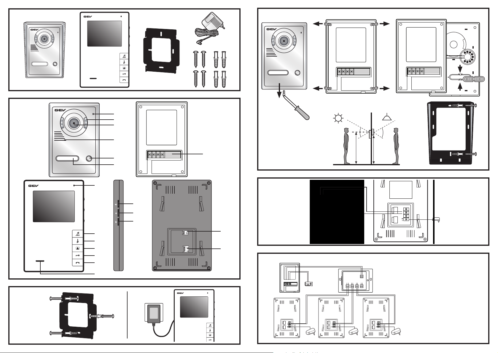
In this Set
1 Rain cover
1 Indoor unit
1 Wall mount bracket for internal unit
1 External power supplies
1 Outdoor unit
Screws
1 Four-pole adapter cable
Key assignment/Controls
Outdoor unit (Fig. A)
1 Microphone
2 Infrared light
3 Camera
4 Speaker
5 Doorbell buttons
6 Nameplates
7 Terminal
Indoor Unit (Monitor) (Fig. A)
8 Microphone
9 Volume adjustment
10 Ringtone selection button
11 Monitoring function on/o
12 Door opener button
13 Talk button
14 Speaker
15 Brightness button
16 Contrast control
17 Speaker volume
Connection elements
18 Connection terminal for external power supply
19 Wire connector
Features
2-Family house video door intercom with 16
polyphonic ringtones and 102 mm diagonal screen
size. Splashproof outdoor unit with rain cover and
automatic loudness control, door opener and camera
monitoring function with infrared light. Manually
adjustable call, ringer, brightness and contrast
volume.
Safety instructions
Under no circumstances does the warranty cover
or bodily injury caused by mishandling or failure to
observe the safety instructions. In these cases, no
warranty claim may be made. In addition, for safety
and compliance reasons, you are not authorised to
dismantle or alter the device in any way.
damage resulting from failure to observe
these instructions. Nor do we accept liability
for any indirect damage. Similarly, we can
accept no liability for any material damage
Installation
If in any doubt, rather than mounting, connecting or
installing the equipment yourself, contact a qualified
technician.
Installation of the indoor unit (Monitor)
Attach the wall mount bracket with the three provided
screws to your intended site (Fig. B1). Make sure
that all cable connections are already wired before
installing the indoor unit in the now mounted wall
acket. Then plug the cable of the power supply
br
into the monitor and then the AC adapter into the wall
outlet (Fig. B2).
Installation of the outdoor unit
Lettering of the nameplate
Remove the rain cover: First loosen the screw on the
bottom side (Fig. C1). Then loosen the four screws on
the now exposed backside of the camera unit (Fig.
C2). Now you can lift the cover. You now have the
ability to remove the nameplate and to label it (Fig.
C3). Loosen carefully the rear of the nameplate with an
appropriate screwdriver. Then snap back into place.
Screw the device back together. We recommend a
mounting height of the outdoor unit of about 140 cm
to 170 cm but this can vary depending on your own
circumstances (Fig. C4). Make sure that you do not
expose the unit directly to the weather (e.g. direct
rain). Avoid placing it in direct sunlight. Before the final
assembly, ensure that the indoor and the outdoor unit
are wired correctly and are operational. Please also
note the maximum distance between the individual
elements (see point „Connection“).
To install the outdoor unit on the wall, first screw the
rain cover as shown in Fig. C5 onto the wall. Before
finishing the wall mounting, connect the cables to the
outdoor unit according to the wiring diagram (or see
section „Connection“). Now hook the camera module
in the rain cover and attach the device with the screw
on the bottom.
Connection
Included with the video door entry kit CVB 88320 is
a two-pin adapter cable that you need to connect
with your existing installation cable (not supplied).
For distances between indoor and outdoor unit up to
50 m use at least 2 x 0, 5 mm² cable. Connect the
adapter cable to the monitor (Fig. A18).
Connecting the outdoor unit (Fig. D).
Connect the terminals of the outdoor unit 1 and 2 with
the corresponding lines 1 and 2 of the indoor unit (see
wiring diagram). Connect the outdoor unit with a door
opener (not supplied) (Fig. D). Connect terminals 3
and 4 of the outdoor unit with the door opener.
Connect the power supply to the monitor’s designated
end of the power supply with the „+“ and “-“marked
terminals. If you need a door opener, we recommend
from our range Order no. 007680/007642 (110 mm) or
007697/007666 (250 mm).
Activation/Operation
By pressing the call button (Fig. A5), an acoustic
signal is triggered at the indoor units and the monitors
turn on. You can speak with the guest by briefly
pressing on the talk button (Fig. A13). The talking
time is approximately 120 seconds. You can end the
conversation at any time by pressing again the talk
button. Without user activity the panel automatically
switches to stand-by mode after about 40 seconds.
Press the door opener button (Fig. A12) in order to
open the door. By pressing the monitoring function
(Fig. A11) you can monitor at any time the area
covered by the camera. After about 40 seconds the
system switches back in stand-by mode. You can
adjust the brightness (Fig. A15) and contrast (Fig.
A16) of the screen, by adjusting the control dial.
Between the 16 polyphonic ringtones you select by
(2-Wire installation)
pressing the ringtone selection button (Fig. A10).
The same applies for the volume control (Fig. A9).
Confirm your entries each with a press of the talk
button (Fig. A13).
Expansion options
You can operate in this system up to 3 indoor
units (order no.: 088481). Furthermore you need a
distributor (order no.: 088528) (Fig. F).
Other Notes
Do not install the indoor units where they are
exposed to high temperatures and humidity or
in the vicinity of TV sets. Do not touch the sensor
buttons with wet hands. To clean the monitor or the
camera, do not use cleaning agents. Simply use a
damp cloth. Do not install the camera and the indoor
unit in occurrence of direct light. Do not install near
electronic devices (TV, Computer, telephones), as
this may lead to disturbances of the system.
Recycling instructions
This device may not be disposed of with
unsorted household waste. Owners of old
devices are required by law to dispose of this
device correctly. Contact your town council for
further information.
Troubleshooting
Problem Check point
No power
(no picture on monitor)
Power is on, but no picture on the
monitor
The picture is too dark or white • Adjustbrightnesscontrol
Chime sound is too low • Adjustthevolumecontrol
• Isthepowersupplyconnectedcorrectly?
• Isthecablermlyconnectedbetweenthemonitorandthe
camera?
• Isthepolarityofwirescorrectbetweentheoutdoorcamera
unitandindoormonitorunit?
Technical information CVB 88320
Indoor unit (88481) Specifications
Supply voltage DC 15 V
Rated power operation max 10 W
Stand-by < 0.1 W
Monitor TFT-LED 102 mm diagonal screen size
Resolution 320 x 240 pixels
Operating temperature -5 °C to 40 °C
Mounting method surface mounted
Dimensions approx. W 125 x H 190 x D 26 mm
Power Supply (for each indoor monitor) Specifications
Input voltage 230 V~, 50 Hz
Output voltage DC 15 V
Rated current 1.2 A
Outdoor Unit (8832001) Specifications
Camera CCD sensor > 420 TV lines
Operating temperature -20 °C to +50 °C
Mounting method surface mounted
Door opener max. 12 V/1.0 A
Dimensions approx. W 85 x H 142 x D 38 mm
Technical and design features may be subject to change without notice.
76
GB
 Loading...