


GE
TRAN SP OR TATION
SYSTEMS
GLOBAL SIGNALING DIVISION
Author:
Date:
Title:
COE Communications Engineering Document
Keith Gilbertson
3/08/02
Rev:
Pag
A
1
e:
of
12RII FCC TECHNI CAL MANUAL
33

COE Communications Engineering Document
GE
TRAN SP OR TATION
SYSTEMS
GLOBAL SIGNALING DIVISION
1. Scope.....................................................................................................................................................................................3
2. Revision History...................................................................................................................................................................3
3. Reference Documents............................................................................................................................................................ 3
4. Abbreviations and Acronyms................................................................................................................................................ 3
5. 12RII Radio Systems............................................................................................................................................................. 4
5.1. AAR Remote Radio System.......................................................................................................................................... 4
5.2. Clean Cab Radio systems..............................................................................................................................................6
5.3. Serial Remote Radio Systems (Future Option).............................................................................................................. 8
5.4. Radio Final Assembly Parts List...................................................................................................................................8
5.5. Radio Front Assembly Parts List (LC version Only)..................................................................................................... 9
6. Radio Architecture.............................................................................................................................................................. 11
6.1. RC Radio Block Diagram............................................................................................................................................12
6.2. LC Radio Block Diagram............................................................................................................................................13
6.3. SR Radio Block Diagram............................................................................................................................................ 14
6.4. Radio Interfaces Signals.............................................................................................................................................. 15
7. Kenwood RFPA & TXRX Modules.................................................................................................................................... 20
8. POWER SUPPLY BOARD.................................................................................................................................................20
8.1. General Description....................................................................................................................................................20
8.2. Block Diagram............................................................................................................................................................ 20
8.3. Board Interface Signals...............................................................................................................................................21
8.4. External Interface Voltages..........................................................................................................................................21
8.5. RFPA Interface Voltages.............................................................................................................................................21
8.6. RCB Interface Voltages...............................................................................................................................................21
8.7. Power Supply Board Parts List...................................................................................................................................22
8.8. Power Supply Board Schematic..................................................................................................................................23
9. RADIO CONTROL BOARD .............................................................................................................................................. 23
10. General Description........................................................................................................................................................23
10.1. Microprocessor & Digital Interface........................................................................................................................23
10.2. Audio Circuits.........................................................................................................................................................24
10.3. Audio Drivers......................................................................................................................................................... 26
10.4. External I/O Interfaces.............................................................................................................................................27
11. Block Diagram................................................................................................................................................................ 28
12. FRONT PANEL..............................................................................................................................................................29
Standard 12RII Front Panel Controls....................................................................................................................................... 29
Block Diagram........................................................................................................................................................................ 30
12.1. Front Panel Parts List..............................................................................................................................................31
12.2. Front Panel Board Parts List...................................................................................................................................32
12.3. Front Panel Schematic............................................................................................................................................. 33
Author:
Keith Gilbertson
Date:
3/08/02
Title:
12RII FCC TECHNI CAL MANUAL
TABLE OF CONTENTS
Rev:
Pag
A
2
of
e:
33
COE Communications Engineering Document
GE
TRAN SP OR TATION
SYSTEMS
GLOBAL SIGNALING DIVISION
Author:
Date:
Title:
Keith Gilbertson
Pag
3/08/02
12RII FCC TECHNI CAL MANUAL
Rev:
A
3
e:
of
1. Scope
This document provides the necessary technical information to comply with the requirements for FCC certification. This
document will be superseded by the 12RII Service Manual when issued.
2. Revision History
REV DATE BY COMMENTS
A 3/8/02 KLG Initial Release FCC distribution only.
3/19/02 JCK Added FCC Information to the User
33
3. Reference Documents
AAR Communication Manual – Section 12
12RII Part Number Assignment Document
TK-790/(B) Service Manual
4. Abbreviations and Acronyms
12RII-LC 12RII Local Control Radio (Control Panel Installed)
12RII-RC 12RII Remote Control Radio (Interface to Standard AAR Control Head)
12RII-SR 12RII Serial Remote Control Radio (Interface to Serial Remote Control Head)
AAR Association of American Railroads
DTMF Dual Tone Multi-Frequency (standard telephone tones).
FCC Federal Communication Commission
FM Frequency Modulation
FP Front Panel Assembly
FPB Front Panel Board
GETS General Electric Transportation Systems
GS Global Signaling
GSPN Global Signal Part Number
PC Personal Computer
PSB Power Supply Board
PTT Push – To - Talk
RCB Radio Control Board
RPM Radio Processor Module

COE Communications Engineering Document
GE
TRAN SP OR TATION
SYSTEMS
GLOBAL SIGNALING DIVISION
Author:
Date:
Title:
Keith Gilbertson
Pag
3/08/02
12RII FCC TECHNI CAL MANUAL
Rev:
A
4
of
e:
33
5. 12RII Radio Systems
The 12RII radio supports 3 major types of FM voice radio systems or applications. AAR Remote Control (RC), Locomotive
Clean Cab (LC) and Serial Remote (SR). All have similarities in basic radio operation. The major difference between the RC
and LC applications is the type of user interface. The RC uses the AAR standard interface for remote control radios. This
interface is defined in section 12-10 of the AAR C&S Manual. The LC radio has a built in control panel on the front of the
radio. Interfaces to the LC radio are defined in section 12-2 of the AAR C&S Manual. The SR radio system is identical to the
standard LC radio except that the front panel is installed in a remote mounted control head.
Note 1: This device complies with Part 15 of the FCC Rules. Operation is subject to the condition that this device does not
cause harmful interference.
Note 2: Changes or modifications to this device not expressly authorized by the manufacture could void the user’s authority to
operate the equipment.
Note 3: This equipment has been tested and found to comply with the limits for a Class B digital device, pursuant to part 15 of
the FCC rules. These limits are designed to provide reasonable protection against harmful interference in a residential
installation. This equipment generates, uses, and can radiate radio frequency energy and, if not installed and used in
accordance with the instructions, may cause harmful interference to radio communications. However, there is no guarantee that
interference will not occur in a particular installation. If this equipment does cause harmful interference to radio or television
reception, which can be determined by turning the equipment off and on, the user is encouraged to try to correct the interference
by one or more of the following measures:
- Reorient or relocate the receiving antenna.
- Increase the separation between the equipment and the receiver.
- Connect the equipment into an outlet on a circuit different from that to which the receiver is connected.
- Consult the dealer or an experienced radio/TV technician for help.
Note 4: FCC RF Radiation Exposure Statement
This equipment complies with FCC RF radiation exposure limits set forth for an uncontrolled environment. This equipment
should be installed and operated with a minimum distance of 20cm between the radiator and your body.
Note 5: Professional installation of radio and antenna system is required to ensure proper operation and installation of this
equipment. To conform to FCC RF Radiation Exposure limits the installer must remain at least three meters away from the
transmitting antenna when the unit is transmitting. The antenna must be mounted on the top of the train engine as directed in the
installation guide.
5.1. AAR Remote Radio System
5.1.1. General Description
The 12RII-RC radio is compatible with the current 12R-RC radio in all its existing AAR Remote Applications. Refer to the
block diagram in the following section. In the AAR Remote application the primary interface for controls and audio signals is
with an external AAR compatible Control Head or Control Panel. Optionally an AAR handset can be connected to the rear of
the radio at J2. Antenna connection is provided through J1.
The 12RII-RC radio will mount onto the standard 12MT-1 AAR mounting adaptor. The radio will get locked into the 12MT-1
adaptor tray and they are installed as a unit onto a standard AAR Mounting Base such as the 1MB-1. The Mounting base
provides terminal blocks that allow the train wiring from the control panel and battery to be interfaced into a standard cable
supplied with the 1MB-1. This cable mates to J5 on the 12RII radio and provides power and control interface.
COE Communications Engineering Document
A
g
GE
TRAN SP OR TATION
SYSTEMS
GLOBAL SIGNALING DIVISION
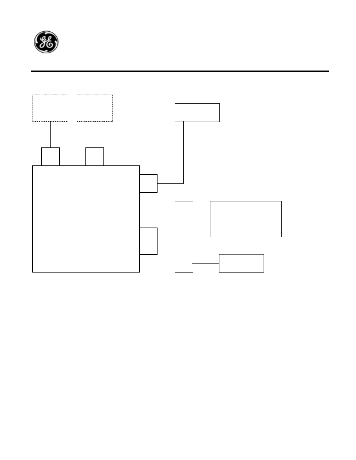
5.1.2. AAR Remote Radio System Block Diagram
Author:
Date:
Title:
Keith Gilbertson
3/08/02
12RII FCC TECHNI CAL MANUAL
Rev:
Pag
A
5
of
e:
33
PC Handset
J2J3
12RII-RC
AR Remote
Radio System
J1
J5
Antenna
M
o
u s
n e
t
i
n
Cab Controls
Aud io Interfac es
Battery
5.1.3. Basic Operation
The AAR Remote Radio is capable of performing all standard radio functions associated with transmitting and receiving radio
signals. The operator selects channels 1-12 from a channel selector. The channel selector drives 5 parallel channel lines to the
appropriate logic levels to cause the radio to go to the desired channel. A PTT (Push-To-Talk) signal line provides radio TX
control request from the operator. Other input control lines that may be applicable and associated with handset cradle or hangup functions are Mute, Quiet Line Disable, and Channel Revert. Additionally, certain customer applications require outputs that
provide indications of radio status such as Standby, Busy or TX.
The audio interfaces available at the J5 connector are microphone transmit audio, 10 watts speaker audio and a low level
receive audio signal. All audio levels are fixed.
The radio handset connector provides interface to a standard AAR handset. The handset interface provides for a PTT transmit
control signal, microphone audio, and receive audio.
The radio receives power from the locomotive or car battery. Battery input voltages are 74VDC for freight and locomotive
applications, and 37VDC in some light rail applications. A 13V battery input is also an option which is to be used for .
The radio typically supplies an output voltage of 13VDC to power the remote control head.
A connector is provided on the radio to interface to a standard personal computer (PC). This is a standard RS-232 interface
used to upload and download radio configuration files, radio status or diagnostics, and radio firmware. These functions are
supported through a special application program “12RIISETUP” program which is loaded on the PC.
COE Communications Engineering Document
GE
TRAN SP OR TATION
SYSTEMS
GLOBAL SIGNALING DIVISION
Author:
Date:
Title:
Keith Gilbertson
Pag
3/08/02
12RII FCC TECHNI CAL MANUAL
Rev:
A
6
of
e:
33
5.2. Clean Cab Rad io systems
5.2.1. General Description
The 12RII-LC radio is compatible with the current 12R-LC radio in all its existing clean cab Applications. Refer to the block
diagram in the following section. In the clean cab application the primary interface for controls and audio signals is a front
panel located on the front of the radio. The radio also supports the standard Handset connector and program connector.
Antenna connection is provided through J1.
The 12RII-LC radio mounts onto the standard 17MT-1 AAR mounting Tray. The Mounting tray is typically located in an
enclosure similar to one specified in the AAR C&S manual in section 12-2. Power to the radio is provided through connector
J4. Typical locomotive battery voltage is 74VDC. Some transit light rail cab cars may provide 37VDC as the primary radio
voltage.
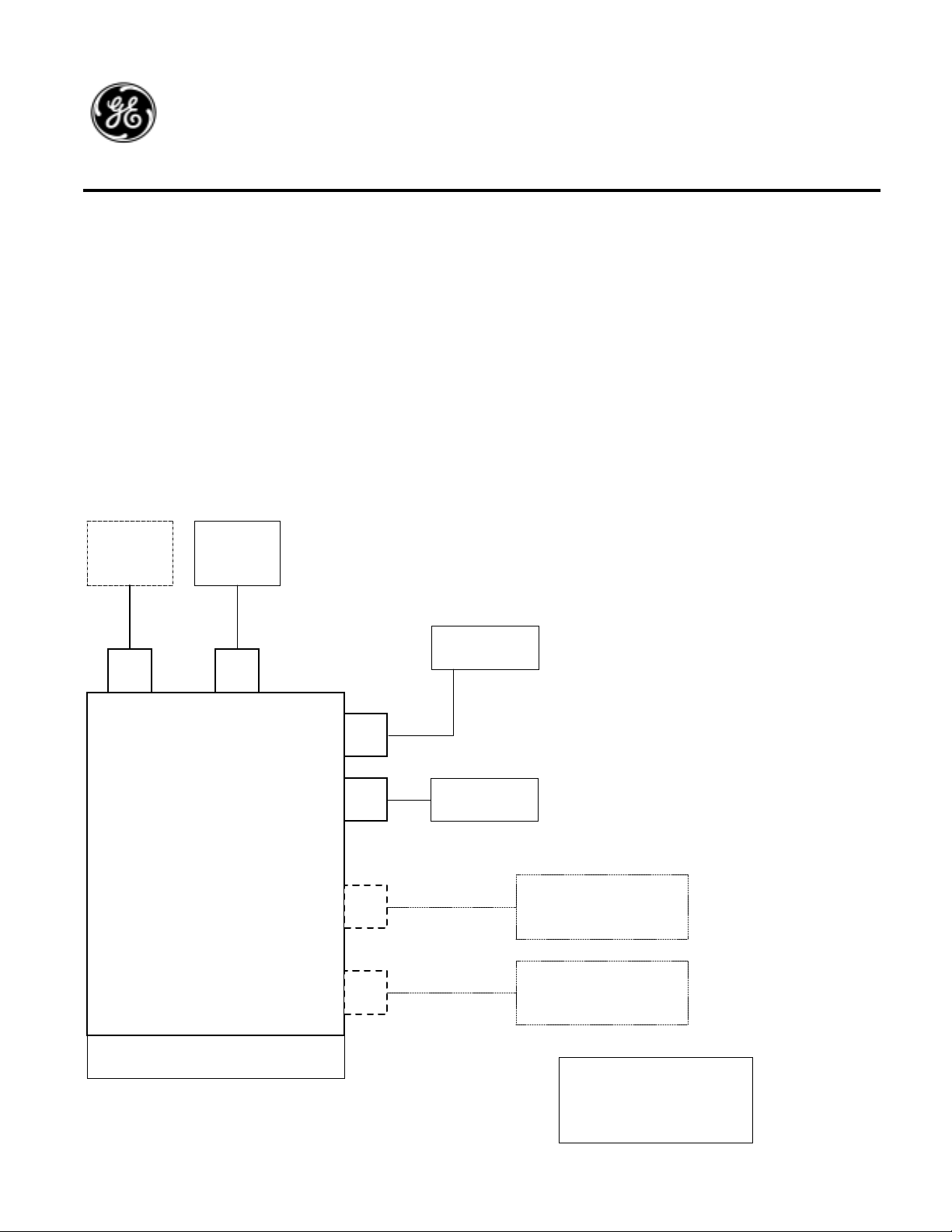
5.2.2. Block Diagram
PC Handset
J2J3
12RII-LC
Clean Cab Radio
System
FRONT PANEL ASSEMBLY
J1
J4
J6
J8
Antenna
Battery
Optional Handset
&
speaker
Optional 2nd
Serial Remote
Control Head
NOTE:
Only one optional interface;
Accessory Option (J6) or Secondary
Serial Remote (J8) may be installed
at the same time.
5.2.3. Basic
Oper
ation
The Clean Cab
Radio is
capable of
performing all
standard radio
functions
associated with
transmitting and
receiving radio
signals. The
operator
controls are via
buttons on the
front panel.
Front panel
controls allow
for a variety of
channeling
controls,
volume, PTT,
and various
special
functions. The
front panel also
supports a full
12-character
phone pad
interface for
DTMF

COE Communications Engineering Document
GE
TRAN SP OR TATION
SYSTEMS
GLOBAL SIGNALING DIVISION
signaling. Audio interfaces on the front panel include a front panel microphone, which is activated with the front panel PTT
button, and a radio speaker.
Optionally, the radio may have an accessory connector (J6) that is used for external controls and audio interfaces or an
interface to a serial control head (J8). J8 provides the necessary serial, audio and control lines necessary to support a front
panel assembly that is packaged in a Remote Control Head.
J6 provides a second handset or microphone input, a second speaker output, and some I/O lines that can provide control inputs
or indication output signals depending on the customer application. As inputs these control lines can be programmed to provide
functions associated with handset cradle or hang-up functions such as Mute, Quiet Line Disable, and Channel Revert.
Additionally, certain customer applications require outputs that provide indications of radio status such as Standby, Busy or
TX.
The radio can support only the Accessory J6 connector or the Optional second control head on J8, not both at the same time
without compromised performance. Audio signals are shared between the two options. However it is not likely that both
options would ever be required in a given application. The radio may have both connectors installed, but only one interface is
likely to be active at a time. This will allow for a “standard” radio to be installed in either of the identified optional
installation configurations.
Author:
Date:
Title:
Keith Gilbertson
Pag
3/08/02
12RII FCC TECHNI CAL MANUAL
Rev:
A
7
of
e:
33
The radio receives power from the locomotive or car battery. Battery input voltages are 74VDC, or 37VDC. The radio
provides 13VDC outputs to power the accessory audio circuitry if necessary and to power the Serial Remote Control Head.
A connector is provided on the radio to interface to a standard personal computer (PC). This is an RS-2323 interface used to
upload and download radio configuration files, radio status or diagnostics, and radio firmware. These functions are supported
through a special application program “12RIISETUP” program which is loaded on the PC.

COE Communications Engineering Document
GE
TRAN SP OR TATION
SYSTEMS
GLOBAL SIGNALING DIVISION
Author:
Date:
Title:
Keith Gilbertson
Pag
3/08/02
12RII FCC TECHNI CAL MANUAL
Rev:
A
8
of
e:
33
5.3. S erial Remote Radi o Syst ems ( Future Option)
5.3.1. General Description
The standard 12RII-SR radio is identical in operation to the 12RII-LC radio except that it is not mounted in the typical brake
stand enclosure. The Serial Remote Control Head that is used in conjunction with the 12RII-SR radio is mounted in the control
stand location. The radio is mounted in a locker or in the nose of the engine. A Serial Interface Cable is used to connect the
radio to the control head.
Optionally the radio supports the connection of a second control head on J8 and a radio handset at J2. Program connector J3 is
also standard as on the other radio systems.
5.3.2. Block Diagram
PC Handset
J2J3
12RII-SR
Serial Remote Radio
System
J1
J4
J7
J8
Antenna
Battery
Primary
Serial Remote
Control Head
Optional 2nd
Serial Remote
Control Head
5.3.3. Basic
Oper
ation
Operation of
the 12RII-SR
radio is
identical to the
12RII-LC
radio. The
front panel
assembly is
identical in
both radio
systems.
5.4. Radi
o
Fina
l
Asse
mbl
y
Part
s
List
251303-0000 A SSY 12RI I - LC 74V VHF X
251303-0001 A SSY 12RI I - LC 74V VHF W/J6 X
251303-0100 A SSY 12RI I - LC 36V VHF X
251303-0101 A SSY 12RI I - LC 36V VHF W/J6 X
251303-1000 A SSY 12RI I - RC 74V VHF X
COE Communications Engineering Document
GE
TRAN SP OR TATION
SYSTEMS
GLOBAL SIGNALING DIVISION
251303-1100 A SSY 12RI I - RC 36V VHF X
GSPN DESCRIPTION QTY QTY QTY QTY QTY QTY
017157-402 PWR SPLY VICOR 74V 1 1 1
017157-401 PWR SPLY VICOR 36V 1 1 1
227409-000 ASSY POWER SUPPL Y BOAR D 74 V 1 1 1
227409-001 ASSY POWER SUPPL Y BOAR D 36 V 1 1 1
180381-790 KIT 12R II TK-790 PARTS 1 1 1 1 1 1
227408-000 ASSY RADIO CO NTROL BOARD 1 1 1 1 1 1
202926-000 ASSY RADIO PROCESSOR MODULE 1 1 1 1 1 1
227410-000 FRONT PANEL ASSEMBLY 1 1 1 1
065373-200 CHASSIS 1 1 1 1 1 1
027105-000 HANDLE 1 1 1 1 1 1
123306-100 BOTTOM COVER 1 1 1 1 1 1
123305-100 TOP COVER 1 1 1 1 1 1
022206-002 BLANK FRONT COVER PLAT E 1 1
123348-100 SIDE COVER PLATE (BLANK) 1 1 1 1
123348-100 SIDE COVER PLATE W/J 5 1 1
123347-101 COVER PLATE J6 1 1 1 1
123347-100 COVER PLATE J4 1 1
202150-611 CA BLE ASSY RCB/ FPB 1 1 1 1 1
202150-610 Cable Assy PSB/RCB 1 1 1 1 1 1
202150-510 CA BLE ASSY (J5) 1 1
202150-410 CA BLE ASSY J6 1 1
202150-110 CA BLE ASSY (J4) 1 1 1 1
202150-210 CA BLE ASSY (J2&J 3 ) 1 1 1 1 1 1
202150-010 CA BLE ASSY 3" RED W /ferrit e 1 1 1 1 1 1
202150-005 CA BLE ASSY 3" BLK R A/ RG 1 1 1 1 1 1
013496-3410 SCREW 4-40 X 5/ 16 PPH ITL SS 51 51 47 47 47 47
013496-3416 SCREW 4-40 X 1/ 2" PPH ITL SS 7 7 7 7 7 7
013496-3610 SCREW 6-32X5/ 16 PPH ITL SS 9 9 9 9 9 9
013492-3616 SCREW 6-32 X 1/ 2 PPH SS 4 4 4 4 4 4
202174-002 ASSY XFORMER 1 1
013492-3716 SCREW 8-32 X 1/ 2 PPH SS 2 2
013002-014 WASHER 8 I NTL SS 2 2
013009-3701 N U T 8-32 HEX SS 2 2
013008-021 WASHER #8 FLT SS 2 2
113114-000 CAM LOCK 1 1 1 1 1 1
013492-3912 SCREW 10-32 X 3/ 8 PPH SS 2 2 2 2 2 2
013030-008 WASHER 10 SPL SS 2 2 2 2 2 2
013002-011 WASHER 6 I NTL SS 2 2 2 2 2 2
013009-3602 WASHER #6 FLT SS 2 2 2 2 2 2
013678-412 SCR EW 4- 40X3/ 8 CT SK SS 2 2 2 2 2 2
005035-001 CLAMP CABLE .187 DIA 1 1 1 1 1 1
005019-017 CABLE TIE 4L NAT 5 5 3 3 3 3
Author:
Date:
Title:
Keith Gilbertson
Pag
3/08/02
12RII FCC TECHNI CAL MANUAL
Rev:
A
9
e:
of
33
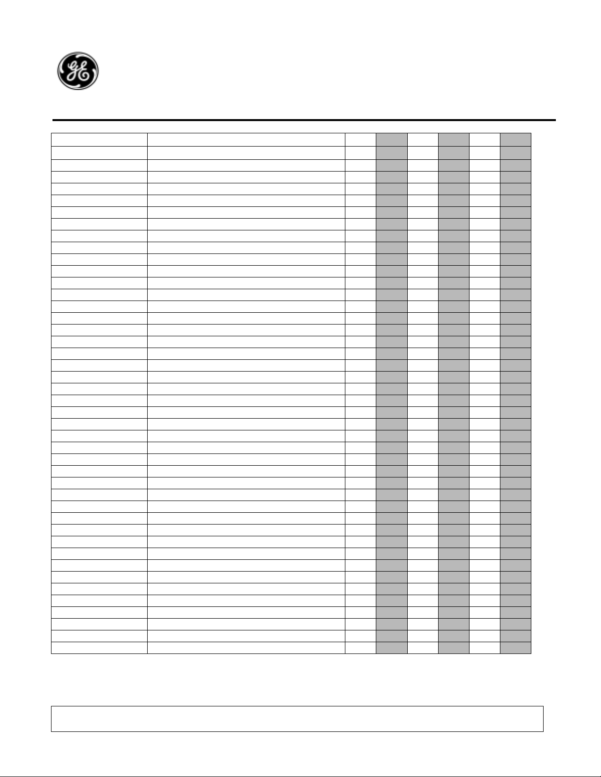
5.5. Radio Front Assembl y P art s List (LC version Only)
227410-000 ASSY 12RII FRONT PANEL
COE Communications Engineering Document
GE
TRAN SP OR TATION
SYSTEMS
GLOBAL SIGNALING DIVISION
GSPN DESCRIPTION QTY REF DES / DIN
227410-100 ASSY 1 2RII FRONT PANEL BO ARD 1 1
202926-000 ASSY 1 2RII PROCESSOR MODULE 1 2
022207-100 Keypad Left 1 6
022207-200 Keypad Nu m er ic 1 7
022207-300 Keypad Righ t 1 8
006128-000 Foam 12R Speaker inser t 1 15
006128-001 Foam 12R Mic inser t 1 16
123363-001 GRILLE 12R SPEAKER 3.3 5 1 14
202298-100 PANEL 12RI I FRONT W/LENS 1 5
013492-3810 SCREW 10-24X5/ 16 PPH SS 4 12
013496-3410 SCREW 4-40 X 5/ 16 PPH I 12 10
227173-001 ASSY SPEAKER 4 OHM 1 4
202167-001 ASSY L CD 12RII 2x1 6 1 3
Author:
Date:
Title:
Keith Gilbertson
Pag
3/08/02
12RII FCC TECHNI CAL MANUAL
Rev:
e:
10
A
of
33

COE Communications Engineering Document
GE
TRAN SP OR TATION
SYSTEMS
GLOBAL SIGNALING DIVISION
Author:
Date:
Title:
Keith Gilbertson
Pag
3/08/02
12RII FCC TECHNI CAL MANUAL
Rev:
A
11
of
e:
33
6. Radio Architecture
The radio and control head architecture is depicted in the following block diagrams for each of the radio applications. The
radio deck in all applications is built around a common chassis.
Radio architecture was determined largely by the requirement to integrate in the TK-790 RF modules, and the need to integrate
circuit functions into fewer boards.
Standard radio modules for the radio deck are the Power Supply Board (PSB), RF Power Amplifier (RFPA),
Transmit/Receive Board (TXRX), Radio Control Board (RCB), and Radio Processor Module (RPM).
Standard connectors for all radios are; J1-Antenna, J2-Handset and J3-program connectors. Application or radio type specific
connectors are J4, J5, J6, J7 & J8.
The front panel assembly is made up of the Front Panel Board (FPB), RPM, LCD and Speaker assemblies. The front panel
assembly is installed on the front of the radio chassis for an LC radio. The front panel is also packaged in a remote mounted
enclosure to make a Serial Remote Control Head.

GE
TRAN SP OR TATION
SYSTEMS
GLOBAL SIGNALING DIVISION
6.1. RC Radio Block Diagram
Author:
Date:
Title:
COE Communications Engineering Document
Keith Gilbertson
3/08/02
Rev:
Pag
A
12
e:
of
12RII FCC TECHNI CAL MANUAL
J2
HANDSET
J3
PGM
33
ANTENNA
POWER
&
CONTROL
J1
J5
J1-J4
P1-P4
12RII-RC
Radio
PSB
RFPA
CN4
J5
J6
J7
CN2
GND
P7
J3 P2
J3 J11 J2
J6
P6
J5
P5
J9
J10
CN1
CN3
W2
TXRX
CN203
CN104
CN201
CN202
RADIO CONTROL BOARD
U1
RADIO
J1A
PROCESSOR
MODULE
J1B
J4
J7J8
T1
P4

GE
TRAN SP OR TATION
SYSTEMS
GLOBAL SIGNALING DIVISION
6.2. LC Radio Block Diagram
Author:
Date:
Title:
COE Communications Engineering Document
Keith Gilbertson
3/08/02
Rev:
Pag
A
13
e:
of
12RII FCC TECHNI CAL MANUAL
33
ANTENNA
POWER
ACCESSORY
(option)
CONTROL
Optional
2nd
HEAD
J1
J4
J6
J1-J4
P1-P4
OPTION
MODULE
12RII-LC
Radio
HANDSETPGM
J
1
J6 J5
FRONT
PANEL
RPM
FPB
U1
PSB
J2
HANDSET
RFPA
CN4
J5
J6
J7
CN2
GND
J7
P3 P2
J3 J11 J2
CN1
CN3
W2
TXRX
CN203
CN104
CN201
CN202
J3
PGM
RADIO CONTROL BOARD
J6
P6
J5
J9
J1
P9
J10P10
J8
P8
J1A
J8
J1J2J3
J3J4
J
2
P1
LCD
U1
RADIO
PROCESSOR
MODULE
J1B
J6 J5
J
1
FPB
U1
RPM
FRONT
PANEL
J4
J7
P7
P3
J3J4
J
2
P1
LCD

GE
TRAN SP OR TATION
SYSTEMS
GLOBAL SIGNALING DIVISION
6.3. S R Radio Block Diagram
Author:
Date:
Title:
COE Communications Engineering Document
Keith Gilbertson
3/08/02
Rev:
Pag
A
14
e:
of
12RII FCC TECHNI CAL MANUAL
J2
HANDSET
J3
PGM
33
ANTENNA
POWER
ACCESSORY
(option)
CONTROL
Optional
2nd
HEAD
J1
J4
J6
J1-J4
P1-P4
OPTION
MODULE
12RII-SR
Radio
HANDSETPGM
J
1
RPM
J6 J5
FRONT
PANEL
FPB
U1
PSB
RFPA
CN4
J5
J6
J7
J1
CN2
GND
P7
P3 P2
J3 J11 J2
J6
P6
J5
J9
P9
J10
P10
J8
P8
CN1
CN3
W2
J8
J1J2J3
J3J4
J
2
P1
LCD
CONTROL
HEAD
TXRX
CN203
CN104
CN201
CN202
RADIO CONTROL BOARD
U1
RADIO
J1A
PROCESSOR
MODULE
HANDSETPGM
FPB
J
U1
1
RPM
J6 J5
FRONT
PANEL
J1B
J4
J7
P7
J7
J1J2J3
J3J4
J
2
P1
LCD

COE Communications Engineering Document
GE
TRAN SP OR TATION
SYSTEMS
GLOBAL SIGNALING DIVISION
Author:
Date:
Title:
Keith Gilbertson
Pag
3/08/02
12RII FCC TECHNI CAL MANUAL
Rev:
A
15
e:
of
6.4. Radio Interfaces Signals
This section identifies the Interface signals associated with each connector used in the radio system(s).
6.4.1. External Connector Conf igurat ions
The following table shows the standard radio connectors associated with each of the typical RC, LC & SR radio systems.
Although other connector options are possible, this list covers all possible applications knows to date.
33
J1
Radio Model Description
RC – AAR Remote X X X X
LC – Clean Cab X X X X
LC – Clean Cab W/Access X X X X X
LC – Clean Cab W/ 2nd Control Head X X X X *X
SR – Serial Remote X X X X X
SR – Serial Remote W/2nd Control Head X X X X X X
* J8 may be physically mounted on radio in the location typically used by J6. This is to allow for connection to existing cables
which may be to short to reach J8 location on the chassis.
** In some applications J6 is a 15 pin connector.
6.4.2. J1 Antenna
J1 is an industry standard UHF (SO-49) connector used to interface to the voice radio antenna. J1 is connects to CN4 on the
RFPA board with a short piece of wire. This connector is common to all radio systems.
6.4.3. J2 6-Pin Handset
J2 supports an interface to a standard AAR 6-pin handset. Connector Pins, Signal Names, and descriptions are shown in the
table below. This connector is standard on all radio systems and interfaces in a common cable with J3 Program connector to J2
on the RCB.
Antenna
J2
Handset
J3
PGMJ44-PinJ523-Pin
J6 **
12-PinJ7Serial 1J8Serial
2
J2 AAR HANDSET SIGNAL INTERFACE
J2-Pin Signal Description Mating Connector
A Mic-Audio Modulation Input from the handset condenser. RCB J2-1
B Mic-Com Microphone Audio return (common with radio chassis). RCB J2-2
C PTT Push-To-Talk radio key input. RCB J2-3
D PTT-Com PTT Return (common with radio chassis). RCB J2-4
E Rec-Audio Audio output to receiver element in handset. RCB *J2-5
F HK Optional “Off Hook signal input. RCB *J2-6
* Either of these signals may be connected to J2-10 if interfacing to a DTMF Palm Mic which requires B+ voltage.
6.4.4. J3 9-Pin Program
J3 provides an interface to a PC used for uploading and downloading firmware, radio statistics or configuration files. This is a
standard 9-pin Mini-D connector. This connector is standard on all radio systems and interfaces in a common cable with J2
Handset connector to J2 on the RCB. J3 interface signals are shown below.

COE Communications Engineering Document
GE
TRAN SP OR TATION
SYSTEMS
GLOBAL SIGNALING DIVISION
J3-Pin Signal Description Mating Connector
2 Rx Data RS-2323 Serial Receive Data Input RCB J2-7
3 TX Data RS-2323 Serial Transmit Data Output RCB J2-8
5 Com Signal Common (common to radio chassis). RCB J2-9
6.4.5. J4 4-Pin Power Connector
J4 is used for primary and secondary input voltages for the 12RII-LC and 12RII-SR radio systems. The J4 cable plugs into J1J4 on the Power Supply Board. J4 typical signal interfaces are shown in the table below.
J4-Pin Signal Description Mating Connector
A +74VDC Primary isolated input voltage PSB J1 / J2
B 13 VDC Com Common (radio chassis). PSB J4
C -74VDC Primary isolated input voltage return. PSB J2 / J1
D +13 VDC Secondary (Test) radio input voltage. PSB J3
Author:
J3 PROGRAM SIGNAL INTERFACE
J4 4-PIN POWER SIGNAL INTERFACE
Keith Gilbertson
Date:
3/08/02
Title:
12RII FCC TECHNI CAL MANUAL
Rev:
Pag
A
16
of
e:
33
6.4.6. J5 23-Pin Power & Control
J5 is used for input power, contr ol and audio signal interfaces on the 12RII-RC radio. The J5 cable assembly plugs into J1-J4
on the Power Supply Board and J5 & J6 on the Radio Control Board.
The Following tables are the currently defined power interfaces used on 74V, 37V and 13V AAR Remote Control Radio
systems.
Standard 74 & 37 Volt Power Input.
J5 23-PIN POWER SIGNAL INTERFACE (STD)
J5-Pin Signal Description Mating Connector
1- -2 * +VIN Isolated input voltage PSB J1
3 * -VIN Isolated input voltage return PSB J2
4 +13VDC 13V Output PSB J3
5 13V COM 13V Common (radio chassis) PSB J4
* Radio must be specified as either 74V or 37V.
Alternate 37V Power Input.
J5 23-PIN POWER SIGNAL INTERFACE (37V ALT.)
J5-Pin Signal Description Mating Connector
1- -2 -3 * -VIN Isolated input voltage return PSB J2
4 * +VIN Isolated input voltage PSB J1
5 13V COM 13V Common (radio chassis) PSB J4
* These are for an alternate 37V Battery Interface.
13V Power Input.
J5 23-PIN POWER SIGNAL INTERFACE (13V Only)
J5-Pin Signal Description Mating Connector
1 13V RTN Non-Isolated input voltage return PSB J1
2 +13V Non-Isolated Input voltage PSB J2
3- -4 +13VDC 13V Output PSB J3
5 13V COM 13V Common (radio chassis) PSB J4

COE Communications Engineering Document
GE
TRAN SP OR TATION
SYSTEMS
GLOBAL SIGNALING DIVISION
The following table illustrates the standard control and audio signals.
J5 23-PIN CONTROL & AUDIO SIGNAL INTERFACE
J5-Pin Signal Description Mating Connector
6 Mic-Com Remote Microphone audio return RCB J6-2
7 Mic-Audio Remote Microphone audio input RCB J6-1
8 8 Ohm Audio Out 10W 8 ohm audio speaker output RCB J5-3
9 PTT Remote PTT input RCB J6-3
10 CH1 AAR Channel 1 Input Select Line RCB J5-4
11 CH2 AAR Channel 2 Input Select Line RCB J5-5
12 CH3 AAR Channel 3 Input Select Line RCB J5-6
13 CH4 AAR Channel 4 Input Select Line RCB J5-7
14 * TX Ind. I/O 1- transmit indication output RCB J6-9
15 Rec-Audio Remote low level receive audio output RCB J6-5
16 Audio Return Audio Common (radio chassis) RCB J6-7
17 * Standby I/O 2 - Standby indication output RCB J6-10
18 Channel Return AAR Channel Return Input RCB J5-8
19 N.C. -20 13V Com Common (radio chassis) RCB J6-8
21 +13V Out Low Power 13V Output, fuse protected RCB J6-6
22 * QL Disable I/O 3 - QL disable input RCB J5-1
23 *Mute I/O 4 - Speaker Mute RCB J5-2
* I/O signals are programmable for user configurations. Signal functions are shown for reference only.
Author:
Date:
Title:
Keith Gilbertson
Pag
3/08/02
12RII FCC TECHNI CAL MANUAL
Rev:
A
17
of
e:
33

COE Communications Engineering Document
GE
TRAN SP OR TATION
SYSTEMS
GLOBAL SIGNALING DIVISION
6.4.7. J6 12-Pin Accessory
The 12-Pin Accessory connector is a typical option on the 12RII-LC radio. The J6 cable assembly plugs into J6 on the Radio
Control Board. The typical interface signals are shown below.
Note: As an alternate for some applications a 15 pin connector is supplied. Signal interface is identical except for pins M &
N. Speaker outputs are replaced with I/O-3 & I/O-4 signals.
J6 12-PIN ACCESSORY SIGNAL INTERFACE
J6-Pin Signal Description Mating Connector
A Mic-Audio Remote Microphone audio input RCB J6-1
B Mic-Com Remote Microphone audio return RCB J6-2
C PTT Remote PTT input RCB J6-3
D PTT Return PTT common (radio chassis). RCB J6-4
E Rec-Audio Remote low level receive audio output RCB J6-5
F +13V Out Low Power 13V Output, fuse protected RCB J6-6
H Audio Return Audio Common (radio chassis) RCB J6-7
J 13V Com Common (radio chassis) RCB J6-8
K * TX Ind. I/O 1- transmit indication output RCB J6-9
L * Standby I/O 2 - Standby indication output RCB J6-10
#M Speaker + Remote Speaker Output RCB J6-11
#N Speaker - Remote Speaker Output RCB J6-12
* I/O signals are programmable for user configurations. Signal functions are shown for reference only.
# On alternate 15 pin connector these signals are I/O-3 & I/O-4 respectively, mating to J5-1 & J5-2 on the RCB.
Author:
Date:
Title:
Keith Gilbertson
Pag
3/08/02
12RII FCC TECHNI CAL MANUAL
Rev:
A
18
of
e:
33
6.4.8. J7 Primary Control Head
J7 is installed on the standard 12RII-SR radio as the primary control head interface. The J7 cable assembly plugs into J7 on the
Radio Control Board. Interface signals are shown in the table below.
J7 19-PIN CONTROL HEAD SIGNAL INTERFACE
J7-Pin Signal Description Mating Connector
J B+ 13V output to control head, fused. RCB J7-1
M Common 13V Return RCB J7-2
U RS485-A Serial Interface, differential current loop output RCB J7-3
S RS485-B Serial Interface, differential current loop output RCB J7-4
A Mic-Audio Control Head 1 Mic audio input to radio RCB J7-5
V Rec-Audio Low level receive audio to control head 1 RCB J7-6
F I/O I/O-3 ID signal to Control Head 1 RCB J7-7
T I/O I/O-4 Master/Slave or Enable signal to Control Head 1 RCB J7-8
K Speaker + Speaker output signal to Control Head 1 RCB J7-9
L Speaker - Speaker output signal t Control Head 1 RCB J7-10
N N.C. Not Connected RCB J7-11
E Shield Serial Cable Shield (radio chassis) RCB J7-12
6.4.9. J8 Secondary Control Head
J8 is an optional connector on 12RII-LC and SR radios to add a second control head interface. The J8 cable assembly plugs
into J8 on the Radio Control Board. Interface signals are shown in the table below.

COE Communications Engineering Document
GE
TRAN SP OR TATION
SYSTEMS
GLOBAL SIGNALING DIVISION
J8 19-PIN CONTROL HEAD SIGNAL INTERFACE
J8-Pin Signal Description Mating Connector
J B+ 13V output to control head, fused. RCB J8-1
M Common 13V Return RCB J8-2
U RS485-A Serial Interface, differential current loop output RCB J8-3
S RS485-B Serial Interface, differential current loop output RCB J8-4
A Mic.-Audio Control Head 1 Mic audio input to radio RCB J8-5
V Rec-Audio Low level receive audio to control head 2 RCB J8-6
F I/O I/O-1 ID signal to Control Head 2 RCB J8-7
T I/O I/O-2 Master/Slave or Enable to Control Head 2 RCB J8-8
K Speaker + Speaker output signal to Control Head 2 RCB J8-9
L Speaker - Speaker output signal t Control Head 2 RCB J8-10
N N.C. Not connected RCB J7-11
E Shield Serial Cable Shield (radio chassis) RCB J8-12
Author:
Date:
Title:
Keith Gilbertson
Pag
3/08/02
12RII FCC TECHNI CAL MANUAL
Rev:
A
19
of
e:
33

COE Communications Engineering Document
GE
TRAN SP OR TATION
SYSTEMS
GLOBAL SIGNALING DIVISION
Author:
Date:
Title:
Keith Gilbertson
Pag
3/08/02
12RII FCC TECHNI CAL MANUAL
Rev:
A
20
of
e:
33
7. Ke nwood RFPA & TX RX Modul es
The Radio Control Board interfaces the TXRX modules on J11 flex circuit connector. All controls to the RF modules are
through this connection. See the Appendix on Kenwood modules for descriptions and block diagrams.
8. POWER SUPPLY BOARD
8.1. General Description
The 12RII Power Supply Board (PSB) provides the regulated voltages necessary from the host battery input voltage of 74VDC
found on most locomotives, or 37VDC found on typical transit cars. The primary battery inputs voltages are isolated from the
radio chassis and internal voltages by the DC/DC converter module.
The primary battery input as well as the secondary 13V input is protected against reverse polarity. The DC/DC converter is
protected with Transient Voltage Suppression (TVS), filtering, and Over Voltage Protection (OVP) circuits to avoid damage of
the converter or the internal radio circuitry.
The PSB provides regulated 13VDC, 8VDC and 5VDC signals to power the internal radio modules.
8.2. Block Diagram
J4
C
D
A
B
BLU
ORN
RED
BLK
POWER SUPPLY
J1
J2
J3
J4
+Vin
-Vin
+13.6V
-13.6V
F1
F2
+V
T
V
S
T
V
S
LC
FILTER
CAP
FILTER
W2
BLK
COMMON
MODE
FILTER
J6 J5
B+
COM
RED
O
V
-V
COM B+ 8V 5V
W1
P
J7
W3
U2
8V
REG
CONVERTER
U3
5V
REG
-
PS1
DC/DC
+
LC
FILTER
TO
RFPA
TO
RCB

COE Communications Engineering Document
GE
TRAN SP OR TATION
SYSTEMS
GLOBAL SIGNALING DIVISION
Author:
Date:
Title:
Keith Gilbertson
Pag
3/08/02
12RII FCC TECHNI CAL MANUAL
Rev:
A
21
of
e:
33
8.3. Board Interf ace S ignals
8.4. E xt ernal Interface V ol t ages
External voltages are connected to the PSB on terminals J1-J4. These voltage signals can come from Radio Connector J4 in a
12RII-LC or 12RII-SR radios. In a 12R-RC radio they are connected to radio connector J5
8.4.1. J1 (+Vin)
The primary battery positive voltage is connected to this input terminal.
8.4.2. J2 (–Vin)
The primary battery negative voltage is connected to this input terminal.
8.4.3. J3 (B+ )
This terminal can be used for an input or an output. To be used as an output, the proper primary battery voltage must be applied
to terminals J1 & J2. The regulated output of the DC/DC converter is available at this terminal. If this terminal is to be used as
a B+ (12 – 15VDC) test input for the radio, there cannot be a primary battery signal connected to terminals J1 or J2.
8.4.4. J4 (Com)
This terminal is used to connect to the radio ground or common signal. It is also connected to radio chassis.
8.5. RFPA Interf ace V ol t ages
8.5.1. J5 (B+)
This terminal is used to supply the high current regulated B+ voltage directly to the RFPA Module.
8.5.2. J6 (Com)
This terminal is used to connect circuit common directly to radio chassis.
8.6. RCB Interface V ol t ages
8.6.1. J7-1, 2, & 3, ( B+)
Three circuit pins are used to connect the regulated 13.4VDC of the DC/DC converter to the RCB board.
8.6.2. J7-4 (+5V)
This circuit pin is used to provide +5VDC to the RCB module.
8.6.3. J7-5 (+8V)
This circuit pin is used to provide +8VDC to the RCB module.
8.6.4. J7-6, 7, & 8(Com)
These three circuit pins are used to connect the radio common to the RCB module. Circuit common is also connected to radio
chassis.

COE Communications Engineering Document
GE
TRAN SP OR TATION
SYSTEMS
GLOBAL SIGNALING DIVISION
Author:
Date:
Title:
Keith Gilbertson
Pag
3/08/02
12RII FCC TECHNI CAL MANUAL
Rev:
8.7. P ow er S up ply Board Parts Li st
227409-001 ASSY 36V POWER SUPPLY BRD X
227409-000 ASSY 74V POWER SUPPLY BRD X
GSPN DESCR IPTION QTY QTY REF DES / DIN
001011-002 CAP ALUM 35V 220U F R AD LS 5 1 C21
001011-205 CAP ALUM 200V 10U F 0. 2RAD L/S 2 C8-9
001011-110 CAP ALUM 100V 33U F 0. 2RAD L/S 2 C8-9
001026-021 CAP CER 500V .01U F 20%Z5U DISC 2 2 C6-7
001129-2024 CAP CER DISK 3000V .01U F 20% 4 4 C1-2 C18-19
001152-081 CAP TAN T SOL 20V 10UF 10% AX 2 2 C24-25
001152-087 CAP TAN T 25V 1UF 10% AXIAL 1 1 C12
001152-227 CAP TAN T SOL 25V 47UF 10% AU 2 2 C 13-14
001258-024 CAP CER SPI N 100V 1000PF 10% 3 3 C10 C17 C20
001258-062 CAP CER SPI N 50V . 1uf 10% X7R 7 7 C11 C16 C22-
001284-100 CAP PYEST 250V . 47U F 5% . 59R AD 1 1 C3
001387-101 CAP ALUM 200V 1500U F SN P 35X40 2 C4-5
001387-102 CAP ALUM 100V 3300U F SN P 35X40 2 C4-5
002129-7109 RES CF 1/2W 1 O HM 5% 2 2 R1-2
003227-000 IC LM340T VOLTAGE REGULAT O R 5V 1 1 U3
003227-002 IC LM340T COM 8VR EG TO220 1 1 U2
010001-028 FUSE 3AG 250V 4A SLO BLO GLA 1 F1
010001-035 FUSE 3AG 250V 6.25A SLO BLO GLA 1 F1
010021-001 MOV 14VRMS 1000A 4J .3" RAD 1 1 RV2
010042-006 MOV 130VRMS 6500A 70J .3" RAD 1 1 RV1
010101-005 FUSE FAST BLO 15A AUTOMOT IVE 1 1 F2
011013-043 DIODE 1N6288A 1.5KE51A TS PL 2 D3-4
011013-029 DIODE 1N6281A 1.5KE27A TS PL 2 D3-4
011144-001 DIODE MR756 RECT 600V 6A 2 2 D1-2
016244-000 IND 140U H 40AM P 1 1 L3
016258-000 IND 15u H 1 1 L4
016246-013 INDU CT CM CH O KE 2MH 7.5A 4R AD 1 1 T2
016263-003 INDU CT O R 285UH 2 L1-2
016263-010 INDU CT O R 100UH 2 L1-2
029749-000 RTV 0.02 0.02 6
032507-000 TERMINAL .250 TAB 6 6 J1-6
032022-008 CO N N 8CKT 2M M HEADER 1 1 J7
032003-000 SO CKET VICOR MAXI SM T 4-PIN OUTPUT 1 1 2
032003-001 SO CKET VICOR MAXI SM T 5-PIN INPUT 1 1 3
032866-003 FUSEHOLDER PC VERT MT H 1 1 5
132222-000 SCKT FU SE CLIP AU TO 15A 2 2 4
062311-000 PCB 12RII PO WER SU PPLY 1 1 1
135630-000 SCHEM 12R II PO W ER SU PPLY REF REF
23 C26-28
A
22
of
e:
33

COE Communications Engineering Document
GE
TRAN SP OR TATION
SYSTEMS
GLOBAL SIGNALING DIVISION
Author:
Date:
Title:
Keith Gilbertson
Pag
3/08/02
12RII FCC TECHNI CAL MANUAL
Rev:
e:
8.8. P ow er S up ply Board Schemati c
See attached drawing 135630-000
9. RADIO CONTROL BOARD
10. General Description
The Radio Control Board is separated into 3 major functional areas. These three major functional areas are;
1) Microprocessor & serial interfaces
2) Audio Interfaces
3) External I/O Interfaces.
23
A
of
33
All External Interfaces terminate at the Radio Control board with the exception of the primary input voltage, which terminates
in the Power Supply Board and the Antenna connection that terminates in the RFPA Module.
10.1. Microp rocessor & Digi t al Interface
10.1.1. Radio Processor Module
The Radio Processor Module (RPM) used in the 12RII Radio is an RCM2020 from Rabbit Semiconductor. This module
contains an 8-bit microprocessor with RTC, 128K RAM, 256K FLASH, and power up supervisory circuitry. The RCB
provides filtered +5V to the RPM. The RPM provides 5 8-bit programmable ports which are used on the RCB to provide
serial interface and digital control of the support circuits on the RCB and interfaces to other radio modules.
The FLASH memory on the RPM contains the radio operating firmware as well as the Radio Configuration File (RCF). The
RCF allows modification of the radio operating frequencies, audio parameters, Front Keypad ooperation (LC version Only)
and I/O programming.
10.1.2. Non-Volatile Memory
The RCB provides for non-volatile storage of board specific parameters in a serial EEPROM device. Also contained is the
board ID number and customer ID number.
10.1.3. Temperature Sensor
An onboard temperature sensor is used to provide temperature information for diagnostic purposes and for allowing some radio
parameters to be varied over temperature.
10.1.4. Serial Interfaces
The RCB supports the following External Serial Interfaces. All external serial interfaces are asynchronous.
RS-485
The RS-485 interface is used to communicate to the Front Panel Board in LC and SR radios. This interface is not used on the
RC version of the radio.

COE Communications Engineering Document
GE
TRAN SP OR TATION
SYSTEMS
GLOBAL SIGNALING DIVISION
RS-232 (2)
Two RS-232 ports are provided. The primary RS-232 port is connected to radio connector J3. This port is connected to a PC,
for uploading and downloading the Radio Configuration File and for executing the dynamic tuning of radio parameters stored in
EEPROM. The second RS-232 port is for future use.
Author:
Date:
Title:
Keith Gilbertson
Pag
3/08/02
12RII FCC TECHNI CAL MANUAL
Rev:
A
24
of
e:
33
10.2. Audio Circuits
The RCB audio circuits provides the necessary audio interfaces, routing, audio processing and gain control necessary for the
radio operation. Circuitry is also provided to generate & decode necessary radio tones for dispatch call, Sub-Audible Squelch,
and MSK data signals (future).
10.2.1. Transmit Audio Inputs
Three audio inputs (HSMIC, MIC1, and MIC2) are used for transmit modulation. The HSMIC signal comes from the radio
handset interface (J2). MIC1 signal comes form the Front panel, and MIC2 comes from the Remote Interface or the second
serial control head (Optional). These transmit audio input signals will be applied to the TXRX module modulation inputs MB
& MO after processing and filtering. The TXRX module uses a dual point modulation scheme hence the two input signals
required.
10.2.2. Receive Audio Input
The primary receive signal input is the “DET” signal from the TXRX module. This is the discriminator output from the radio
receiver. In Normal operation this receive signal will be processed and applied to the appropriate audio output device such as
the radio speaker or handset element.
An optional input signal “DET2”is provided for in the Option Module connection at J9. This is for future use.
10.2.3. Audio Outputs
The RCB transmit audio outputs are the “MO” and “MB” signals. These signals are applied to the TXRX module to provide
the required dual port modulation.
Normal radio receive audio outputs signals are applied to the radio speaker (located on the front panel) and handset receive
element. These interface signals are “SPKR1” and “HSAUD”. Additionally a Remote Handset and second speaker are
supported by “AUD2” and “SPKR2” signals. “AUD1” signal is used to provide low level receive audio to a Control Head in
the SR Radio system.
10.2.4. Transmit Audio Pre-emphasis
The standard 750us pre-emphasis circuit of the radio is made up from the inverting amplifier in U10 and associated components
R21 and C7.
10.2.5. Receive Audio De-emphasis
The standard 750us de-emphasis circuit is made up from the inverting amplifier in U9 and associated components R12, C5 &
C47.
10.2.6. Routing, Processing & Gain Control
The audio routing, processing and gain control of the audio circuitry are controlled by software through the use of mixed signal
audio processing integrated circuits (IC’s). The radio configuration file contains audio maps for each of the primary operating
modes in the radio. The audio maps allow the signal paths and gains to be adjusted for different radio modes and applications.
These devices and primary functions are listed below;
The MX029 is a digital controlled gain device that allows for input and output selection as well. This device is primarily used
for transmit signal input selection and receive audio output selection as well as providing gain control. Each MX029 also
contains an analog inverting amplifier.

COE Communications Engineering Document
GE
TRAN SP OR TATION
SYSTEMS
GLOBAL SIGNALING DIVISION
The MX829 device provides audio processing and filtering, for transmit audio signals. It also contains a precise limiting
circuit for maximum transmit deviation control. Digital Attenuators provide for electronic adjustment of the transmit signals.
The device contains a normal 300 Hz High Pass filter and 3000 Hz. Low pass filter for normal radio band pass audio
requirements. A 2500 Hz. low pass filter may also be selected for radio narrow band operation.
The MX829 also contains an MSK data radio modem capable of 1200 or 2400 Hz modulation and a DTMF tone generator.
The MX828 device contains circuitry for sub-audible tone encoding and decoding as well as select call tone encoding and
decoding. This device is used as the primary receive audio path and contains a digital band pass filter. The High Pass filter
contained in the MX828 has sharper roll off to eliminate and sub-audible signals from being passed on the the receive audio
devices.
The MX839 contains two digital gain amplifiers, four A/D, and three D/A circuits. Two of these digital amplifiers (U3) are
used to adjust split the main transmit modulation signal and level adjustment for the dual port modulation scheme. The
amplifiers of the second device (U6) are used to select the appropriate receive audio signal as well as provide a fine resolution
gain setting. The A/D and D/A circuits are used for various input and output functions.
Author:
Date:
Title:
Keith Gilbertson
Pag
3/08/02
12RII FCC TECHNI CAL MANUAL
Rev:
A
25
of
e:
33
10.2.7. Dispatch Call Tone G ener at ion
The tone modes used for dispatch call functions are the select call tones generated in the MX828 or the DTMF tones generated
in the MX829. The programming in the RCF determines which tone method is used. The appropriate tone output is enabled
and routed to the TXRX modulation inputs.
10.2.8. Sub-Audible Encode/Decode
The MX828 device provides the necessary sub-audible tone encoding and decoding. The channel attribute parameters in the
RCF determine if the selected radio channel is to have sub-audible squelch tones applied. They can be independent for transmit
and receive functions. Both traditional analog CTCSS and digital DCS code formats are available.
10.2.9. Digital Tuning
In addition to the digital gain control provided for in the audio processing the RCB also provides for digital tuning voltages.
The parameters below are under software “digital” tuning control. The data for these controls is stored in the onboard
EEPROM. All of the digital tuning settings are adjusted for each radio.
Radio Frequency Adjustment
Radio frequency adjustment is accomplished with the DAC output 1 of U3. This output is dc coupled on the MB modulation
input that is connected to the TCXO in the TXRX module.
RF Power Control
RF Power Control is handled by U3 DAC output 2. This output is set to the value stored in EEPROM when ever the radio is
put in transmit mode. Two power levels are available (High and Low), selectable on a per channel basis. These levels are
assigned in the RCF channel attribute data.
Front End Tuning Voltage
Front end selector tuning is accomplished with U3 DAC output 3. This level is set to a fixed level at the specified tuning
frequency. A firmware table adjusts this voltage to allow the front end filter to track the selected receive frequency.
10.2.10. Radio Squelch Operation
The TXRX module provides a filtered noise signal “SQL”. This signal is processed by an A/D 1 input of U3. Software
processes the noise level and compares the sampled input against preset levels for Squelch Open and Squelch Close thresholds.

COE Communications Engineering Document
GE
TRAN SP OR TATION
SYSTEMS
GLOBAL SIGNALING DIVISION
10.2.11. Receive Signal Strength Indication (RSSI)
The RSSI output of the TXRX module is applied to A/D 2 input of U3. This input is processed by software and used during
scan operations to provide quick channel busy detection. The RSSI signal level is also be displayed as a graphic during
channel occupancy for information to the user.
10.2.12. MSK Digital Da t a
The MX829 device provides from 1200/2400 MSK data encoding and decoding. This will be used for radio ANI broadcast or
data transmission at a future time. MSK modulation encoding for 1200 baud signal will generate one cycle of 1200 Hz. for a
logic “1” and one and a half cycles of 1800 Hz. for a logic “0”. MSK modulation encoding for a 2400 baud signal will
generate a half cycle of 1200 Hz for a logic “1” and one cycle of 2400 Hz for a logic “0”. Data modulation is not routed
through the pre-emphasis circuit. It does pass through the standard audio BPF and limiter circuitry in the MX829 device.
10.2.13. Radio TX Signal Paths
Voice Transmission
Voice transmission is initiated by activation of the HS-PTT, REM-PTT or a serial PTT command from a control head. The
appropriate audio map is loaded which will select the assigned input to U10-CH1 (HSMIC, MIC1 or MIC2). They standard
voice transmission audio map will set the gain of U10-CH1 and enable output B. The voice signal will be applied to the preemphasis circuit and be routed through U10-CH2 to be applied to the MIC input of U13 (MX829). Internal to the MX829 the
signal will be filtered. The radio channel programming will determine if the filtering is for wide or narrow band channel
operation. The signal will then pass through a limiter typically set for 80% of maximum system deviation. The output of the
limiter stage is applied to a summing amplifier. The summing amplifier output is routed through two stages of digital
attenuators which are used to set the maximum deviation level. The modulation signal output is applied to inputs of the two
digital amplifiers of U3. Amplifier 1 drives the MB (TCXO) modulation signal and amplifier 2 drives the MO (VCO)
modulation signal.
Author:
Date:
Title:
Keith Gilbertson
Pag
3/08/02
12RII FCC TECHNI CAL MANUAL
Rev:
A
26
of
e:
33
10.2.14. Radio RX Signal Paths
In Receive mode the output of the TXRX module is applied to analog channel 1 input of U6. The output of this amplifier is
applied to the RX input of U14 (MX828). The input amplifier of U14 amplifies the signal. The output is coupled internally to
the input of the audio Band Pass Filter and to the sub-audible and tone decoders for decoding if necessary. The external output
of the amplifier is connected to the Demodulation Input of U13. This input is coupled to the MSK decoder in data applications.
The output of the BPF in U14 is routed to the input of Mod. 1 Attenuator of U14. If the squelch criteria has been satisfied, the
Mod 1 output is enabled and the receive signal passes through the de-emphasis network, amplified
By CH3 of U9 and applied to U9-CH1, U9 CH2, U17-CH1, and U17-CH2 input #2. Depending on the Audio Map loaded for
receive mode, the outputs of U9 and U17 are enabled with the proper gains to drive the appropriate audio speaker or device.
10.3. Audio Drivers
10.3.1. Low Level Audio Drivers
Amplifiers U7-A, U7-B and U12-A are used as low level drivers. Each of the amplifiers is connected an output of U9 or U17.
The amplifiers are non-inverting DC amplifiers with a gains of 3. The outputs are cap coupled through a series impedance of
604 ohms before connection the their respective load devices. The series impedance is used to buffer the low impedance of
handset elements to the driver amplifier. HSAUD signal drives the radio handset element at connector J2. AUD1 signal is used
as low-level audio to control head 1. AUD2 signal is used to drive a remote handset connected to J6 or control head 2 audio.
10.3.2. Speaker Drivers
Two independent speaker drivers, U15 and U16 are used for different applications. Each speaker amplifier has a standby
input that is used to mute the speaker when the radio is not receiving. This signal is controlled by the radio processor module.
The amplifiers also contain a diagnostic signal output which indicates when the amplifier is clipping or has been shut down due
to an output fault condition. These diagnostic signals are monitored by the RPM.

COE Communications Engineering Document
GE
TRAN SP OR TATION
SYSTEMS
GLOBAL SIGNALING DIVISION
A standard clean cab (LC) radio uses Speaker 1 to drive the front panel speaker.
A standard AAR remote radio uses Speaker 2 output coupled through transformer T1 to drive an 8 ohm grounded speaker. The
level is fixed and volume control is external to the radio.
A clean cab radio with optional interface uses Speaker 2 output to drive an external radio speaker. In this application the
external speaker level can be fixed where external volume control is used or it can tracks the radio volume control used for
Speaker 1 output. This is determined by settings in the radio configuration file.
If a second control head is used, the speaker 2 output is used to drive the speaker in the optional control head. The speaker
output level will track the volume adjustments made from control head 2 independent from the volume controls made in the
radio front panel or control head 1.
Author:
Date:
Title:
Keith Gilbertson
Pag
3/08/02
12RII FCC TECHNI CAL MANUAL
Rev:
A
27
of
e:
33
10.4. Extern al I/O Interf aces
10.4.1. Handset s & PT T Inputs
The radio handset (J2) input signals are the PTT and Hook Switch. The PTT input goes low to activate the transmitter when the
handset PTT button is pressed. The Hook Switch input is connected to a cradle switch and used for various controls such a
channel monitor, Scan Start/Stop, and Channel Revert. Each of these circuits for these two signals are the same. A small value
series impedance feeds a pull up resistor and bypass capacitor. The input is then dc blocked by a series diode that only allows
current to flow out the input. This protects the digital radio processor module input that is pulled up to +5V.
The HPTT and HK inputs are monitored by the RPM and will initiate a radio transmission if HPTT goes low or provide the
necessary function assigned to HK should it go active.
The Remote PTT input is the primary PTT input used in the AAR Remote radio through connector J5 interface. This input is
also available in the clean cab version with option accessory connector J6 for interface into a remote communication panel.
This input circuit uses a comparator device (U19-A) to convert 13V logic to 5V logic. A series impedance (R67) is used to
feed the input bypass cap (C77) and pull-up resistor R4. Diode D4 is used to clip small signal transient spikes lower than
radio common or higher than B+. The input is coupled into U19-A positive input at pin 3. If this input is lower than the
reference voltage at the negative input at pin 2, the output will go low. The RPTT signal is monitored by the RPM and will
initiate radio transmit.
10.4.2. Programmable I/O
IO-1, IO-2, IO-3, and IO-4 signals are provided to allow for custom input and output interfaces. The function of each of the I/O
signals is set in the radio configuration file. All four I/O signals are available in Remote connector J5 for us in an AAR
Remote radio. IO-3 and IO-4 are used in normal front panel operation for identification and enabling of the front panel
operation. IO-1 and IO-2 are used in the clean cab radio optional accessory connector interface or for the optional second
control head identification and enabling. Each of the I/O circuits is identical. IO-1 circuit operation is as follows;
10.4.3. AAR Channel Inputs
The AAR channel selection is done with 5 input lines. These 5 lines are separated into 4 channel select lines and a channel
return line. 12 Channel remote control is defined per AAR channel table logic.

GE
TRAN SP OR TATION
SYSTEMS
GLOBAL SIGNALING DIVISION
11. Block Diagram
J11-TXRX
B+
+8VB++8V
COM
COM
PC
PC
TV
TV
RSSI
RSSI
SQL
SQL
DET
DET
KEY
KEY
CK
CK
ES
ES
DT
DT
MB
MB
MO
MO
CP
CP
EP
EP
UL
UL
J2-HS/PGM
B+
COM COM
HS-MIC
HS-AUD
HSAUD
HS-PTT
HSPTT
HS-HK
HSHK
TXD1
232-TXD1
RXD1
232-RXD1
J6-ACC/REM
B+
COM COM
Mic
REM-MIC
Term.
REM-AUD
AUD2
REM-PTT
REMPTT
I/O-1
IO-1
I/O-2
IO-2
SPK+
SPKR2+
SPK-
SPKR2-
J5-REM
IO-3
IO-3
IO-4
IO-4
PWRAUD
PAUD
CH1
CH1
CH2
CH2
CH3
CH3
CH4
CH4
CHRTN
CHRTN
TXD2
232-TXD2
RXD2
232-TXD2
J7-FPB/CH1
B+
COM
COM
CH1-MIC
MIC1
CH1-AUD
AUD1
485-A
485-A
485-B
485-B
SPK1+
SPKR1+
SPK1-
SPKR1-
IO-3
IO-3
IO-4
IO-4
B+
Mic
Term.
B+
MIC2
J3-PSB
B+
+5V
+8V
1
HSMIC
2
MIC1
3
MIC2
1
2
CK
SERCLK
SDI
DATA
CS3
LE
Pre-emphasis
MX839
DET
DET2
ACH1
ACH2
A/D
ACH3
ACH4
CK
CLK
SDI
CD
SDO
RD
CS7
CS
COM
U10-A
MX029
CH 1
CH 2
CH 3
U6
D/A
A
B
A
IRQ
COE Communications Engineering Document
Author:
Date:
Title:
+5V
J1A
Mic
Mic/Demod
Demod In
CK
SDI
SDO
CS1
INT0
U14
MX828 Sub-Audio Processor
Rx Amp
Control Interface
CLK
CK
DAOUT2
CD
SDI
RD
SDO
CS
CS2
IRQ
INT0
INT0
Keith Gilbertson
3/08/02
12RII FCC TECHNI CAL MANUAL
RADIO PROCESSOR MODULE
J1B
PA0
PA3
PA2
PA1
PA4
PA5
PA6
PA7
PB2
PB1
PB0
PB3
PB4
PB5
PB6
PB7
PE2
PE1
PE0
PE3
PE4
PE5
PE6
PE7
BEN
PC0
PC3
PC2
PC1
PC4
PC5
PC6
PC7
PD2
PD1
PD0
PD3
PD4
PD5
PD6
CS3
CS4
CS5
CS6
CS7
ES
HPTT
SP1EN
SP2EN
HK
RPTT
CHR
485-EN
KEY
INT0
CS1
CS2
SUB-AUD
U13
MX829 Audio Processor
RX
En
Anti
Audio Filters &
Alias
Audio Limiter
Control Interface
CLK
CD
RD
CS
IRQ
Filter
Amp2
Mod2 En
BW
MSK Rx
En
CD
MSK-CD
Tone
Sum
Gen.
Sub-Aud
Audio BPF &
6dB attenuator
Amp
Gen.
Amp2
Mod2 En
Sub-Audio
Sub-Audio
BPF
Decoders
Tone
Decoder
DAC
INT1
SP1EN
Sum
Amp
MSK Tx
DTMF
Encoder
En
CK
KEY2
SP2EN
En
En
Mod. 1
Atten.
Mod. 2
Atten.
Comp.
SDI
SDO
En
PCLK
Vol.
Atten.
Mod. 1
Atten.
Mod. 2
Atten.
SUB-AUD
TXD1
TXD2
RXD1
RXD2
485-TX
485-RX
De-emphasis
PC2
CPDTEP
CDET
UL
CK
SDI
CS4
CK
SDI
CS5
SQL
RSSI
B+
8V
CK
SDI
SDO
CS6
SCL
SDA
1
2
3
1
2
SERCLK
DATA
LE
1
2
3
1
2
MX839
A/D
CLK
CD
RD
CS
PD7
STAT
MSK-CD
U9-A
MX029
CH 1
CH 2
CH 3
U17-A
MX029
CH 1
CH 2
CH 3
SERCLK
DATA
LE
U3
D/A
IRQ
A
U12-A
B
A
A
U7-B
B
A
MOD2
MB
MO
PC
TV
INT0
Rev:
Pag
485-EN
485-RX
AUD2
U7-A
AUD1
e:
LT1785
OE
RE
D
R
AB485-A
485-B485-TX
SP1
U15
EN
SP1EN
HSAUD
SP2
U16
EN
SP2EN
TXD1
RXD1
TXD2
RXD1
SPK1+
SPK1-
SPK2+
SPK2-
28
MAX202
T1I
T1O
R1O
R1I
T2I
T2O
R2I
R2O
SPK2+
SPK2PAUD
A
of
232-TXD1
232-RXD1
232-TXD2
232-RXD2
DET2
MOD2
KEY2
PC2
CDET
DAOUT2
J4
P1
P2
S1
S2
33
SCL
SDA
SCL
SDA
T1
24C64
SCL
SDA
LM75
T
SCL
M
SDA
P
J9 HOT
DET
MOD
KEY
CH1SEL
CH2SEL
CH3SEL
J8-CH2
B+
COM
CH2-MIC
CH2-AUD
AUD2
485-A
485-A
485-B
485-B
SPKR2+
SPKR2+
SPKR2-
SPKR2IO-1
IO-2
COM
MIC2
IO-1
IO-2
HSPTT
HSHK
REMPTT
CHRTN
LOGIC INPUTS
5V
HPTT
HK
RPTT
CHR
IO-1
IO-2
IO-3
IO-4
LOGIC I/O
8574
1
2
SCL
SCL
SDA
SDA
IRQ
INT1
8
B+
3-STATE INPUTS
CH1
CH2
CH3
CH4
ACH1
5V
ACH2
ACH3
ACH4

GE
TRAN SP OR TATION
SYSTEMS
GLOBAL SIGNALING DIVISION
12. FRONT PANEL
Author:
Date:
Title:
12R
COE Communications Engineering Document
Keith Gilbertson
3/08/02
Rev:
Pag
e:
29
12RII FCC TECHNI CAL MANUAL
SERIES
II
AAR ch. 30
BNSF DISP. GRP
TUNE
A
VOLUME
DIM
1 2 3
DTMF
TONE
654
HOME
CHANNEL
GRPGRP
RX
A
of
33
Standard 12RII Front Panel Controls
LCD DISPLAY
Front Panel Mic
Volume Up/Dn
Channel Up/Dn
Numeric Keypad
Home
GRP ^ & GRP v
Tune RX
PTT
“SQUARE”
“CIRCLE”
Displays Channel & Group Names as well as operator prompts and status messages.
Used when the Front Panel PTT switch is depressed to make a transmission.
Adjust level of audio heard over the speaker. Display indicates numeric setting when adjusted.
Used to scroll through the available channels (displayed on top line of LCD) available in the selected channel group (displayed on
bottom line of LCD).
0 – 9, * and # used to generate DTMF dispatch call tones. Keypad will transmit DTMF tones when key is pressed if button is
activated for direct tone generation.
Resets radio channel & group to designated “home” location.
Used to Scroll up and down through the available channel groups;
Active in AAR GROUP only. Used to create “split” channels (TX & RX different). Press to activate and use “channel buttons” to
select desired RX channel.
Used to make a radio transmission using the Front Panel Microphone. Press “PTT” button to activate transmitter, (LCD display will
indicate when radio is transmitting), and speak into the Front Panel Mic opening.
User assigned. Typically assigned for SCAN operation.
User assigned. Typically assigned for Add/Delete function to add or remove channels from the scan list.
7*8 9
0 #
ICOM
SEND
PTT
DIM
“A”
DTMF
TONE
ICOM
SEND
Alters intensity of backlit keypads and LCD for night viewing.
User assigned. Typically assigned for channel monitor. Press to disable radio squelch (audio mute function). Used to test for proper
volume setting (hear noise), or keep receiver squelch open if a reception is breaking up.
Used to select a stored DTMF “phone number string” or to allow entry of a new string of numbers for auto-send function.
Used to select the preprogrammed dispatch call tone for auto-send function
Takes radio to Intercom mode. Pressing again will take out of Intercom mode.
Causes radio to transmit and selected tone signal to be broadcast based on preset timing parameters.

GE
TRAN SP OR TATION
SYSTEMS
GLOBAL SIGNALING DIVISION
Block Diagram
+5V
J1
PA0
PA3
PA2
PA1
PA4
PA5
PA6
PA7
PB2
PB1
PB0
PB3
PB4
PB5
PB6
PB7
PE0
RS
DIM
IN2L
COL1
COL3
COL2
J1-TO RADIO
B+
COM
MIC
REC-AUD
485-A
485-B
SPK+
SPK-
IO
IO
J6-SPKR
SPK+
N.C.
SPK-
J2-HS/PGM
B+
COM COM
HS-MIC
HS-AUD
HS-PTT
HS-HK
TXD1
RXD1
1
2
3
COL4
COL6
COL5
COM
MIC-AUD
REC-AUD
485-A
485-B
SPKR+
SPKRIN1
IN2
HSAUD
HSPTT
HSHK
232-TXD1
232-RXD1
MK1
COL7
COL8
B+
HS-HK
HS-PTT
IN1L
Mic
Term.
A
B
485-EN
B+ +5V
IN2 IN2L
RADIO PROCESSOR MODULE
PE2
PE1
PE3
PE4
PE5
PE6
PE7
BEN
PCLK
E
CK
DB7
DB4
DB5
DB6
R/W
U2
5V
REG
COM
U3-AIN1 IN1L
U3-B
LT1785
OE
485-EN
RE
D
R
485-RX
U7-A
MX029
1
REC-ADU
SDA
CS1
CH 1
2
3
CH 2
1
2
CH 3
SERCLK
CK
DATA
LE
AB485-A
485-B485-TX
A
B
A
J2
PC0
PC1
485-TX
485-RX
SCL
SDA
SCL
SDA
Author:
Date:
Title:
PC3
PC2
PC4
PC5
TXD1
RXD1
24C64
SCL
SDA
LM75
T
SCL
M
SDA
P
MAX202
T1I
TXD1
R1O
RXD1
T2I
VB-EN
R2O
U12-A
U12-A MIC-AUD
COE Communications Engineering Document
Keith Gilbertson
3/08/02
Rev:
Pag
e:
30
12RII FCC TECHNI CAL MANUAL
PC6
PC7
PD0
ROW1
EEPROM
TEMP
SENSOR
T1O
R1I
T2O
R2I
HS-AUD
DB7
DB6
DB5
DB4
PD2
PD1
ROW2
ROW3
232-TXD1
232-RXD1
PD3
PD4
PD5
PD6
PD7
CS1
SCL
SDA
ROW4
K
+-
DIM
On/Off
+5V
V-
LCD
BIAS
GND
RES
STAT
VB-EN
LED Current
Limit
ROW1
ROW1
ROW1
ROW1
COL1
COL2
COL3
COL4
COL5
COL6
COL7
COL8
VBIAS
S1 S2 S3 S5 S6 S7 S8S4
S9 S10 S11 S12 S13 S14 S15 S16
S17 S18 S19 S20 S21 S23S22 S24
SWLED+
DB7
DB6
DB5
DB4
E
R/W
RS
VBIAS
+5V
COM
B+
K
4 x 8 KEYPAD
S29S28S27S26 S25
Keypad LED Back-light
LCD MODULE
J5
31-32
14
DB7
29-30
13
DB6
27-28
12
DB5
25-26
11
DB4
23-24
10
DB3
21-22
9
DB2
19-20
8
DB1
17-18
DB0
7
15-16
6
E
13-14
5
R/W
11-12
4
RS
VBIAS
9-10
3
7-8
VDD
2
5-6
1
VSS
A
3-4
15
LED
K
BACKLIGHT
1-2
16
A
of
33

COE Communications Engineering Document
GE
TRAN SP OR TATION
SYSTEMS
GLOBAL SIGNALING DIVISION
Author:
Date:
Title:
Keith Gilbertson
Pag
3/08/02
12RII FCC TECHNI CAL MANUAL
Rev:
e:
12.1. Front P anel Parts L ist
227410-000 ASSY 12RII FRONT PANEL
GSPN DESCRIPTION QTY REF DES / DIN
227410-100 ASSY 1 2RII FRONT PANEL BO ARD 1 1
202926-000 ASSY 1 2RII PROCESSOR MODULE 1 2
022207-100 Keypad Left 1 6
022207-200 Keypad Nu m er ic 1 7
022207-300 Keypad Righ t 1 8
006128-000 Foam 12R Speaker inser t 1 15
006128-001 Foam 12R Mic inser t 1 16
123363-001 GRILLE 12R SPEAKER 3.3 5 1 14
202298-100 PANEL 12RI I FRONT W/LENS 1 5
013492-3810 SCREW 10-24X5/ 16 PPH SS 4 12
013496-3410 SCREW 4-40 X 5/ 16 PPH I 12 10
227173-001 ASSY SPEAKER 4 OHM 1 4
202167-001 ASSY L CD 12RII 2x1 6 1 3
31
A
of
33

COE Communications Engineering Document
GE
TRAN SP OR TATION
SYSTEMS
GLOBAL SIGNALING DIVISION
Author:
Date:
Title:
Keith Gilbertson
Pag
3/08/02
12RII FCC TECHNI CAL MANUAL
Rev:
A
32
of
e:
33
12.2. Front P anel Board Parts Li st
227410-100 ASSY 12 RII FRONT PANEL BOARD
GSPN DESCRIPTI ON QT Y REF DES / DIN
001358-101 CAP CER CH IP 50V 100pF 0805 5 C17-18 C41 C44-45
001360-102 CAP CER CH IP 50V 1000pF 10% 0805 8 C3-8 C10-11
001360-104 CAP CER CH IP 50V .1UF 10% 0805 20 C2 C9 C12-13 C15-16 C19-22 C25
001377-229 CAP TANT CH IP 1.0uF 20% 16V T AN T3216 3 C14 C26 C32
001377-232 CAP TANT CH IP 4.7uF 20% 16V T AN T3528 4 C23-24 C36 C42
001377-252 CAP TANT CH IP 10uF 20% 25V 7343 2 C1 C31
002266-5681 RES CHP 1/10 680 OHM 5% 0805 2 R41-42
002266-5823 RES CHP 1/8W 82K 5% 805 5 R37 R47 R86-88
002278-1002 RES 10.0K OHM 1/10 W 1% 0805 16 R22 R25 R29 R35 R39 R43 R 72 R75-79
002278-1009 RES 10.0 OHM 1/ 10 W 1% 0805 2 R32-33
002278-1210 RES 121 OHM 1/ 10 W 1% 0805 5 R34 R36 R 49- 50 R 82
002278-1241 RES 1.24K OHM 1/10 W 1% 0805 48 R1-21 R 26 R30 R45 R48 R51-70 R73-
002278-2430 RES 243 OHM 1/ 10 W 1% 0805 4 R23 R27-28 R71
002278-4022 RES 40.2K OHM 1/10 W 1% 0805 7 R24 R31 R 38 R 44 R46 R83 R85
002278-4750 RES 475 OHM 1/ 10 W 1% 0805 1 R40
003377-010 IC M C33072 IND DUAL OPAMP SOI C8P 1 U6
003444-075 IC LM 75 A/D TEMP SENSO R M SO P8 1 U9
003574-004 IC 8KX8 I2C SER EEPR SO8 1 U8
003732-002 IC + 5V R EG LM 10861 1 U2
003738-005 IC LT1785IND RS485 XCVR60V 1 U5
003758-029 IC M X029T N IND DIG TSSOP24 1 U7
003759-000 IC M AX 202 +5V R S-232 TRANSCEIVER 1 U4
004204-000 XSTR MM BT3904 NPN SOT- 23 2 Q1 Q3
004253-003 XSTR N DT 3055LO G IC NFET3.5A S 1 Q2
009330-000 SWITCH SPST M OM W/LED SM T 29 S1-2 9
011040-002 DIO DE MM BD7000LT1 DU AL SWITCHING SOT - 7 D1-7
011233-000 LED ORN CH P 50MW 0805SM T 50M 4 DS1-4
018132-001 MI C EM100T PC MO UNT 1 MK1
018132-102 MI C 100E R U BBER BOOT 1 2
032022-203 CONN HDR 1X3 PIN MAL 2mm SMT 1 J6
032022-210 CONN HDR 1X10 PIN MAL 2mm SMT 1 J4
032022-212 CONN HDR 1X12 PIN MAL 2mm SMT 1 J3
032290-9009 SCKT SN G L . 019DIA TI N CLO SED 2 J7-8
132360-220 CONN SCKT 2x20 2mm SMT 2 J1-2
132360-216 CONN SO CKET 32P SMT BOTTO M EN TRY 1 J5
062312-000 PCB 12RII FRON T PANEL BR D 1 1
135631-000 SCHEM 12RII FRONT PANEL BRD ref
C27-30 C35 C37-40
R81 R84 R89-90
74 R80

GE
TRAN SP OR TATION
SYSTEMS
GLOBAL SIGNALING DIVISION
12.3. Front Panel Schematic
See Attached drawing 135631-000
Author:
Date:
Title:
COE Communications Engineering Document
Keith Gilbertson
3/08/02
Rev:
Pag
A
33
e:
of
12RII FCC TECHNI CAL MANUAL
33
 Loading...