

Getemed VitaGuard 300, VitaGuard 310, VitaGuard 2000, VitaGuard 2100, VitaGuard 3000 Test procedure
...Page 1
Test Procedure
VitaGuard® VG2000 / VG3000 / VG300
Projekt ID: 9204 H1
1 Approvals
Department Name Signature Date
Author
Engineering
Quality Assurance
Valid from: 10.12.2001
Copy to: FE X VK PF QB Others
Revision Author Dept. Datum Design Change Nr.
A R. Downes FE 27.02.01
B R. Downes FE 20.12.01
2 Scope
This document is valid for distributors that satisfy the following conditions:
• the company is certified in accordance with DIN ISO 9003
• the engineers/technicians performing the tests have been training to do so by
getemed AG.
18-Month Regular Inspection
9204-TP-0001-Rev B
3 Purpose
This document describes the tests that should be carried out at least once every 18
months or after the monitor has been returned to the distributor by the user.
4 Reference
1. 9204-TR-0001-Rev B Test Report Document to be copied for each monitor.
5 Investigators
Responsible Technician:
Other technicians:
6 Location
Address of the distributor
7 Start and End Dates
Begin: Start date of test
End: Maximum of 2 hours after starting
9204-TP-0001-Rev B-VitaGuard 18-Month Regular Inspection English.doc Seite 1 von 13
Page 2
Test Procedure
VitaGuard® VG2000 / VG3000 / VG300
Projekt ID: 9204 H1
18-Month Regular Inspection
8 Equipment and Materials
The equipment listed below marked R is the equipment used by getemed AG. Similar
models from other manufacturers can be used as long as the performance is similar.
The model numbers of the equipment listed with getemed AG as manufacturer
correspond with the ordering numbers, should the distributor wish to purchase the
equipment from getemed.
Equipment Model Manufacturer
Power adapter NA2000-2 72126 getemed AG
ECG patient cable 70263 getemed AG
Masimo SpO2 cable PC08 70257 getemed AG, Masimo
Masimo SpO2 Sensor DC I 70254 getemed AG, Masimo
External alarm unit EA1000 70003 getemed AG
Cable for EA1000 70004 getemed AG
PC Interface cable 70262 getemed AG
VitaWin software VitaWin getemed AG
R 1A / 3-6V power supply HM7042 Hameg
R Digital Multimeter Model 87 Fluke
R ECG/Respiration patient simulator 214B DNI Nevada Inc.
R SpO2 patient simulator Oxitest Plus DNI Nevada Inc.
R
Resistor Box 1-3000Ω ±1%
R Stop watch - R Safety tester Unimet 1000 ST Bender
R
Two 4.7kOhm ±1% resistors
R Test PC with Windows 95 or higher - -
9204-TP-0001-Rev B
Mini-Ohm Dekade Präzisionsmesstechnik
- -
9 Procedure
The procedure is divided into 4 sections:
• Visual inspection of the monitor
• Functional measurements
• Safety inspection
• Visual inspection of accessories
For easy reference, the numbers of this procedure correspond with the numbers in
the test report.
Before beginning the test procedure, the revision stand of the monitor should be
checked. The distributor will be notified of any changes as they occur and informed as
to whether these changes should be implemented in older monitors.
Should the monitor under test shows any signs of malfunction, then it must be
returned immediately to getemed AG for inspection.
The test reports must be archived for at least 10 years and made available to
getemed AG on request.
The distributor shall maintain a data bank showing when a monitor was last tested
and by whom.
The remaining part of section 9 explains how to perform the test procedure. To
correspond with the test report, numbering will begin with 9.7.1.
9204-TP-0001-Rev B-VitaGuard 18-Month Regular Inspection English.doc Seite 2 von 13
Page 3
Test Procedure
VitaGuard® VG2000 / VG3000 / VG300
Projekt ID: 9204 H1
18-Month Regular Inspection
9.7.1 Visual inspection of the monitor
The first section of the test report is the visual inspection of the monitor.
9.7.1-1 Labels
All four labels listed in box 1 must be readable and free from damage. If this is the
case, then box 1 can be ticked-off with o.k.
The following labels are readable and not damaged:
• Top label with keys,
• Label on the back of the monitor with serial number and
1
9.7.1-2 Connectors
The connectors listed in box 2 must be fitted tightly. The connector pins must be
visually inspected to ensure that none of them are damaged. If this is the case, then
box 2 can be ticked-off with o.k.
2
9.7.1-3 Casing and LCD display
safety warnings,
• Label stripe at the front marking all inputs,
• Label marking direction of batteries inside the battery
compartment.
The following connectors are fitted tightly and not damaged:
• ECG/PC input,
• power supply input,
• SpO2 input,
• ext. Alarm input (VG3000 and VG300 only).
9204-TP-0001-Rev B
o.k.
o.k.
The monitor casing must not be cracked or have any significant scratches. Special
case must be given to the corners and the areas around the connectors. The LCDdisplay must also be free from damage. If this is the case, then box 3 can be tickedoff with o.k.
3 The monitor casing and the LCD display are not damaged. o.k.
9.7.2 Functional measurements
The second section of the test report involves measuring parameters and performing
functional tests.
The external power adapter NA2000-2 used must be modified to measure the current
flowing to the monitor. To do this, cut the positive wire going to the monitor and attach
two 4mm connector jack plugs to the loose ends. These can then be inserted into a
multimeter.
For measurements with the resistor box, the red and yellow leads form the ECG
patient cable are connected to the resistor box. The black lead is taken from the
center point of two 4.7kOhm resistors connected between red and yellow in order to
avoid an open-lead warning from the black electrode.
9204-TP-0001-Rev B-VitaGuard 18-Month Regular Inspection English.doc Seite 3 von 13
Page 4
Test Procedure
VitaGuard® VG2000 / VG3000 / VG300
Projekt ID: 9204 H1
18-Month Regular Inspection
9204-TP-0001-Rev B
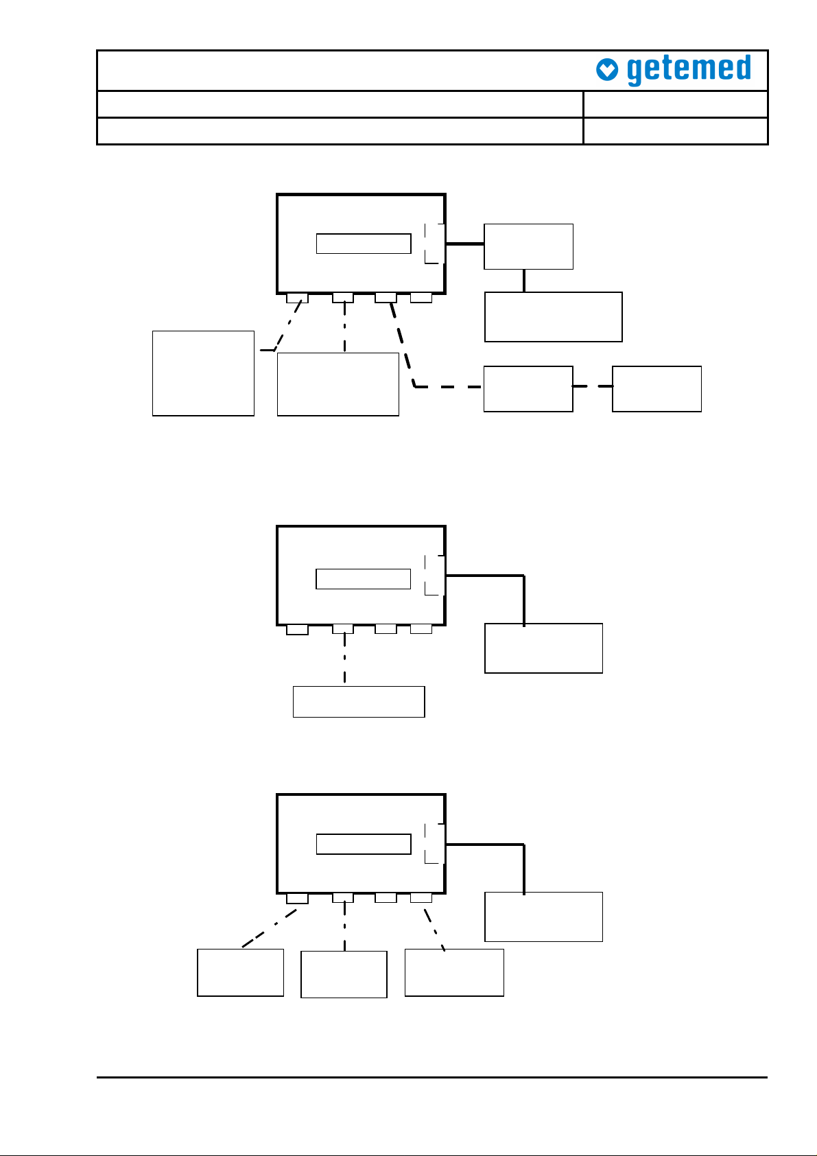
VG2000/3000/300
Monitor
Comp.
Battery
Digital-
Multimeter
(1)
Power supply
3-6V / 2A
Digital-
Multimeter
NA2000-2
SpO2Sensor
and
simulator
(3)
SpO2 ECG
Power
EA 1000
(4)
Patient
simulator
(2)
Figure 1 – Current Measurement Set-Up
VG2000/3000
Monitor
Battery
Comp.
SpO2 ECG Power EA 1000
Power supply
3-6V / 2A
Resistor box
Figure 2 – Basal Impedance Measurement Set-Up
VG2000/3000/300
Monitor
Battery
Comp.
SpO2 ECG
Power
EA 1000
Power supply
3-6V / 1A
SpO2
Simulator
PatientSimulator
ext. alarm
EA1000
Figure 3 – Alarm Measurement Set-Up
9204-TP-0001-Rev B-VitaGuard 18-Month Regular Inspection English.doc Seite 4 von 13
Page 5

Test Procedure
B 3 2 1
NA2000
-
2
VitaGuard® VG2000 / VG3000 / VG300
Projekt ID: 9204 H1
18-Month Regular Inspection
9204-TP-0001-Rev B
VG2000/3000/300
Monitor
Battery
Comp.
SpO2 ECG
Power EA 1000
Power supply
3-6V / 1A
PC
VitaWin
Figure 4 – PC Measurement Set-Up
UNIMET 1000 ST
A
LCD
2000/3000/300
VitaGuard
Figure 5 – Patient Safety Tester
9.7.2-1 Current from batteries when monitor switched off
Connect the monitor as shown in Fig. 1 with NA2000-2 disconnected. Set the output
voltage of the power supply to 6V. Read the current flowing through multimeter (1)
while the monitor is switched off. This value should be less than 200uA. If this is the
case, then enter the value in the box provided.
1 Current from batteries when switched off < 200uA
9204-TP-0001-Rev B-VitaGuard 18-Month Regular Inspection English.doc Seite 5 von 13
Page 6

Test Procedure
VitaGuard® VG2000 / VG3000 / VG300
Projekt ID: 9204 H1
18-Month Regular Inspection
9204-TP-0001-Rev B
9.7.2-2 Current from batteries when monitor switched on
Connect the monitor as shown in Fig. 1 with NA2000-2 disconnected. Set the output
voltage of the power supply to 6V. Switch the monitor on and wait until the standard
display appears. Read the current flowing through multimeter (1). When testing
VG3000 or VG300, read the values with the SpO2 module switched both on and off.
Enter the values in the boxes provided.
2 Current from batteries V2000
when switched on VG300, VG3000 (SpO2 off)
VG300, VG3000 (SpO2 on)
35mA ± 5mA
35mA ± 5mA
265mA ± 20mA
9.7.2-3 Current from batteries when NA2000-2 connected
Connect the monitor as shown in Fig. 1. Connect the external power adapter
NA2000-2 to the monitor and read the current flow through multimeter (1). Enter the
value in the box provided.
3 Current from battery when NA2000-2 connected < 30 µA
9.7.2-4 Current from NA2000-2 when monitor switched off
Connect the monitor as shown in Fig. 1. Switch the monitor off and read the current
flowing through multimeter (2). Enter the value in the box provided.
4 Current from NA2000-2 when monitor switched off
45 mA ± 5mA
9.7.2-5 Current from NA2000-2 when monitor switched on
Connect the monitor as shown in Fig. 1. Switch the monitor on and wait until the
standard display appears. Read the current flowing through multimeter (2). When
testing VG3000 or VG300, read the values with the SpO2 module switched both on
and off. Enter the values in the boxes provided.
5 Current from NA2000-2 VG2000 < 260mA
when monitor switched on VG300, VG3000 (SpO2 off)
VG300, VG3000 (SpO2 on)
< 260mA
< 530mA
9.7.2-6 Green power LED
Connect the monitor as shown in Fig. 1. When the external adapter NA2000-2 is
connected, the green LED on the bottom right corner of the monitor must illuminate.
This must happen when the monitor is switched on or off.
6 Green LED lights when NA2000-2 connected o.k.
9.7.2-7 LCD backlight
Connect the monitor as shown in Fig. 1. When the external adapter NA2000-2 is
connected and the monitor is switched on, the LCD backlight must illuminate.
7 LCD backlight switches on when NA2000-2 connected o.k.
9204-TP-0001-Rev B-VitaGuard 18-Month Regular Inspection English.doc Seite 6 von 13
Page 7

Test Procedure
VitaGuard® VG2000 / VG3000 / VG300
Projekt ID: 9204 H1
18-Month Regular Inspection
9204-TP-0001-Rev B
9.7.2-8 Switch-over between NA2000-2 and batteries
Connect the monitor as shown in Fig. 1. When the external adapter NA2000-2 is
connected, the monitor switches automatically away from the batteries. When the
adapter is disconnected, the monitor switches back to battery mode. To perform the
test, remove and reconnect the adapter 3 times at the connector input in short
succession. The monitor must operate normally throughout the test. If this is the case,
enter o.k. in the box provided.
8 Automatic change-over between batteries and NA2000-2 o.k.
9.7.2-9 Switch-over between NA2000-2 and batteries
Connect the monitor as shown in Fig. 1. Repeat the test above. This time remove the
external adapter NA2000-2 from the socket. The monitor must operate normally
throughout the test. If this is the case, enter o.k. in the box provided.
9 Automatic change-over when NA2000-2 pulled from socket o.k.
9.7.2-10 Battery display “good”
Remove the NA2000-2 adapter and power the monitor from the Hameg power supply,
as shown in Fig. 1. Set the output voltage to 6V. Using the <INFO> key, read the
battery display. If the value “good” is displayed, then enter o.k. in the box provided.
10 Battery display “good” 6.0V
9.7.2-11 Battery display “weak”
Remove the NA2000-2 adapter and power the monitor from the Hameg power supply,
as shown in Fig. 1. Set the output voltage to 4.5V. Using the <INFO> key, read the
battery display. If the value “weak” is displayed, then enter o.k. in the box provided.
11 Battery display “weak”
4.5V ± 0.2V
9.7.2-12 Battery display “exhausted”
Remove the NA2000-2 adapter and power the monitor from the Hameg power supply,
as shown in Fig. 1. Set the output voltage to 4.1V. Using the <INFO> key, read the
battery display. If the value “exhausted” is displayed, then enter o.k. in the box
provided.
12 Battery display “exhausted“
4.1V ± 0.2V
9.7.2-13 SpO2 module switches off (VG3000 and VG300 only)
Remove the NA2000-2 adapter and power the monitor from the Hameg power supply,
as shown in Fig. 1. Let the monitor run for 30s before proceeding. Slowly reduce the
voltage from 4.5 to 4.0V and note the value at which the SpO2 module switches off.
This value should be 4.2V ± 0.2V. The monitor must display the “SpO2 switched off”
message and sound a technical alarm.
13 SpO2-Module switches off: LCD message + technical alarm
4.2V ± 0.2V
9204-TP-0001-Rev B-VitaGuard 18-Month Regular Inspection English.doc Seite 7 von 13
Page 8

Test Procedure
VitaGuard® VG2000 / VG3000 / VG300
Projekt ID: 9204 H1
18-Month Regular Inspection
9204-TP-0001-Rev B
9.7.2-14 Battery exhausted warning
Remove the NA2000-2 adapter and power the monitor from the Hameg power supply,
as shown in Fig. 1. Let the monitor run for 30s before proceeding. Slowly reduce the
voltage from 4.0V to 3.5V and note the value at which the battery exhausted message
appears. This value should be 3.6V ± 0.2V. The monitor must display the message
and sound a technical alarm.
14 Batteries exhausted: LCD message + technical alarm
3.6V ± 0.2V
9.7.2-15 Power-on with weak batteries
Remove the NA2000-2 adapter and power the monitor from the Hameg power supply,
as shown in Fig. 1. Set the voltage to 3.5V and switch the monitor on. The monitor
must start-up and display the “battery exhausted” message.
15 Monitor switches on at U
= 3.5V; SpO2-Module stays off o.k.
bat
9.7.2-16 Data retention
Connect the monitor as shown in Fig. 1. Set the apnea pause time to 12s and the
lower heart rate to 60bpm. Switch the monitor off and back on again. These values
must reappear.
16 Parameters stay stored when monitor switched off o.k.
9.7.2-17 System LED’s
Connect the monitor as shown in Fig. 1. Switch the monitor off and back on again.
During the start-up phase, the 4 LED’s must illuminate.
17 LED’s activated upon start-up, LCD display o.k. o.k.
9.7.2-18 System buzzer at 4096Hz
Connect the monitor as shown in Fig. 1. Switch the monitor off and back on again.
During the start-up phase, the system buzzer must sound loud and clear.
18 Buzzer sounds loud and clear o.k.
9.7.2-19 System buzzer at 2048Hz
Connect the monitor as shown in Fig. 1. Set the buzzer frequency to 2048HZ under
system settings. Switch the monitor off and back on again. During the start-up phase,
the system buzzer must sound loud and clear.
19 Select 2048Hz option, buzzer sounds loud and clear o.k.
9.7.2-20 System self-test
Connect the monitor as shown in Fig. 1. Execute the self-test under system settings.
This test must pass for both the cardio and the apnea sections.
20 Execute self test (not used for VG300) Test o.k.
9204-TP-0001-Rev B-VitaGuard 18-Month Regular Inspection English.doc Seite 8 von 13
Page 9

Test Procedure
VitaGuard® VG2000 / VG3000 / VG300
Projekt ID: 9204 H1
18-Month Regular Inspection
9204-TP-0001-Rev B
9.7.2-21 Apnea alarm
Set the apnea pause time to 12s. Let the monitor run for 1 minute. Do not press any
keys during this time. Provoke an apnea alarm on the ECG patient simulation (4)
shown in Fig. 1. The monitor must respond with an apnea alarm within 12s ± 2s.
21 Apnea alarm after 12s
12s ± 2s
9.7.2-22 Apnea alarm
Connect the monitor as shown in Fig. 1. Let the apnea alarm continue for a further 15
seconds once the monitor has begun to alarm. The alarm must stay active for the
complete duration. Do not press any keys during this test.
22 Apnea alarm stays active for 15s o.k.
9.7.2-23 Basal Impedance = 500Ohm
Connect the monitor as shown in Fig. 2. Set the resistor box to 500Ω and, using the
<INFO> button, note the value for the basal impedance measured. Ensure that lead 2
is selected.
23
Basal impedance = 500Ω (Lead 2) 500Ω ± 100Ω
9.7.2-24 Basal Impedance = 1000Ohm
Connect the monitor as shown in Fig. 2. Set the resistor box to 1000Ω and, using the
<INFO> button, note the value for the basal impedance measured.
24
Basal impedance = 1000Ω (Lead 2) 1000Ω ± 100Ω
9.7.2-25 Basal Impedance = 1800Ohm
Connect the monitor as shown in Fig. 2. Set the resistor box to 1800Ω and, using the
<INFO> button, note the value for the basal impedance measured.
25
Basal impedance = 1800Ω (Lead 2) 1800Ω ± 200Ω
9.7.2-26 Basal Impedance = 1000Ohm
Change the lead configuration to lead 1 (monitor settings menu). Connect the monitor
as shown in Fig. 2. Set the resistor box to 1000Ω and, using the <INFO> button, note
the value for the basal impedance measured.
26
Basal impedance = 1000Ω (Lead 1) 1000Ω ± 100Ω
9.7.2-27 Basal Impedance = 1000Ohm
Change the lead configuration to lead 3 (monitor settings menu). Connect the monitor
as shown in Fig. 2. Set the resistor box to 1000Ω and, using the <INFO> button, note
the value for the basal impedance measured. Set the configuration back to lead 2
after completing this test.
27
Basal impedance = 1000Ω (Lead 3) 1000Ω ± 100Ω
9204-TP-0001-Rev B-VitaGuard 18-Month Regular Inspection English.doc Seite 9 von 13
Page 10

Test Procedure
VitaGuard® VG2000 / VG3000 / VG300
Projekt ID: 9204 H1
18-Month Regular Inspection
9204-TP-0001-Rev B
9.7.2-28 Open-Lead warnings
Connect the monitor as shown in Fig. 2. Disconnect each electrode individually from
the patient cable. The corresponding open-lead warning message must appear on the
LCD display accompanied by a technical alarm. Do not press any keys during this
test.
28 Warning when each electrode removed (Lead 2) o.k.
9.7.2-29 Open-Lead warnings
Connect the monitor as shown in Fig. 2. Set the resistor box to 3kΩ. The monitor
must display an open-lead warning accompanied by a technical alarm. Do not press
any keys during this test.
29
Warning when impedance above 3kΩ
o.k.
9.7.2-30 Heart rate display
Connect the monitor as shown in Fig. 3 and switch off apnea monitoring (under
system settings menu). Set the lower heart rate limit to 60bpm and the upper limit to
200bpm. Using the patient simulator, increase the heart rate from 30 to 240 bpm in
appropriate steps. Ensure that the same heart rate is displayed on the monitor.
30 Heart rate from 30 – 240bpm
HR ± 2bpm
9.7.2-31 Lower heart rate alarm
Connect the monitor as shown in Fig. 3. Using the patient simulator, set the heart rate
to 40bpm. Once the displayed HR falls below 60bpm, note the time for a bradycardia
alarm to appear. Do not press any keys during this test.
31 Bradycardia alarm when HR = 40bpm <7s
9.7.2-32 Upper heart rate alarm
Connect the monitor as shown in Fig. 3. Using the patient simulator, set the heart rate
to 240bpm. Once the displayed HR increases above 200bpm, note the time for a
tachycardia alarm to appear. Do not press any keys during this test.
32 Tachycardia alarm when HR = 240bpm
15s ± 1s
9.7.2-33 ECG sensitivity
Connect the monitor as shown in Fig. 3 and set the heart rate gain to max. Using the
patient simulator, set the ECG amplitude to 0.5mV. Ensure that 20 consecutive beats
are registered by the monitor by observing the heart rate LED.
33 Heart rate when signal amplitude = 0.5mV o.k.
9.7.2-34 No ECG alarm
Connect the monitor as shown in Fig. 3. Switch the patient simulator off and note the
time for the monitor to produce a QRS! alarm. Do not press any keys during this test.
34 Alarm when no signal present
4s ± 1s
9204-TP-0001-Rev B-VitaGuard 18-Month Regular Inspection English.doc Seite 10 von 13
Page 11

Test Procedure
VitaGuard® VG2000 / VG3000 / VG300
Projekt ID: 9204 H1
18-Month Regular Inspection
9204-TP-0001-Rev B
9.7.2-35 SpO2 sensor off warning
Connect the monitor as shown in Fig. 3. Disconnect the SpO2 sensor from the SpO2
simulator. The monitor must display sensor off alarm and produce a technical alarm.
35 Sensor off: Warning and technical alarm o.k.
9.7.2-36 SpO2 measurements
Connect the monitor as shown in Fig. 3. Set the monitor such that the heart rate is
determined from the Masimo SpO2 module (system settings menu). Set the pulse
rate of the SpO2 simulator to 100bpm. Select 4 SpO2 values from the simulator and
verify that these values are displayed by the monitor.
36 SpO2 set to 86%, 90%, 94%, 98% with HR = 100bpm o.k.
9.7.2-37 Pulse rate measurements
Connect the monitor as shown in Fig. 3. Set the SpO2 simulator to 96%. Select 4
pulse rate values from the simulator and verify that these values are displayed by the
monitor.
37 HR set to 70, 100, 150, 200bpm with SpO2 = 96% o.k.
9.7.2-38 SpO2 low alarm
Connect the monitor as shown in Fig. 3. Set the lower SpO2 limit to 88% and the
upper SpO2 limit to 98%. Let the monitor operate for 1 minute. Set the SpO2
simulator to 70%. Verify that an SpO2 alarm occurs within 10s after the displayed
value falls below 88%. Do not press any keys during this test.
38 SpO2 alarm when SpO2 = 70%
10s ± 1s
9.7.2-39 SpO2 high alarm
Connect the monitor as shown in Fig. 3. Set the lower SpO2 limit to 88% and the
upper SpO2 limit to 98%. Let the monitor operate for 1 minute. Set the SpO2
simulator to 100%. Verify that an SpO2 alarm occurs within 10s after the displayed
value rises above 98%. Do not press any keys during this test.
39 SpO2 alarm when SpO2 = 100%
10s ± 1s
9.7.2-40 EA1000 connection
Connect the monitor as shown in Fig. 3. When the monitor is operating, the green
LED on the EA1000 must flash once every second.
40 Monitor on/off recognised by EA1000 o.k.
9.7.2-41 EA1000 alarm
Connect the monitor as shown in Fig. 3. When the monitor generates an alarm, the
EA1000 must also generate an alarm.
41 Alarm from monitor recognised by EA1000 o.k.
9204-TP-0001-Rev B-VitaGuard 18-Month Regular Inspection English.doc Seite 11 von 13
Page 12

Test Procedure
VitaGuard® VG2000 / VG3000 / VG300
Projekt ID: 9204 H1
18-Month Regular Inspection
9204-TP-0001-Rev B
9.7.2-42 PC connection
Connect the monitor as shown in Fig. 4 and activate the VitaWin software on the PC.
Set the date and time of the monitor. Refer to the VitaWin manual for further
instructions.
42 Set date and time o.k.
9.7.2-43 Alarm episodes
Connect the monitor as shown in Fig. 4 and activate the VitaWin software on the PC.
Download the alarm episodes stored in the monitor from tests 21, 31, 32, 38 and 39.
Examine the tests to ensure that the signals have no interference.
43 Read and analyse stored episodes o.k.
9.7.2-44 Compliance protocol
Connect the monitor as shown in Fig. 4 and activate the VitaWin software on the PC.
Download the compliance protocol and examine the data.
44 Read monitor compliance protocol o.k.
9.7.2-45 Monitor reset
Connect the monitor as shown in Fig. 4 and activate the VitaWin software on the PC.
Reset the monitor.
45 Reset monitor o.k.
9.7.3 Safety inspection
Connect the monitor to the patient safety tester as shown in Fig. 5. Most testers
perform the tests automatically and print out a protocol. This protocol can be attached
to the test report or the values can be entered into the box below.
The tests performed should conform to EN 60601-1, class II, BF (body floating).
9.7.4 Visual inspection of accessories
All the monitor accessories must be visually inspected before use. Special care must
be taken to ensure that all cables and connectors are clean and free from damage.
Any damaged accessories must be replaced. The user manual and the packaging
must also be clean.
9204-TP-0001-Rev B-VitaGuard 18-Month Regular Inspection English.doc Seite 12 von 13
Page 13

Test Procedure
VitaGuard® VG2000 / VG3000 / VG300
Projekt ID: 9204 H1
18-Month Regular Inspection
Nr
1 Visual inspection of ECG cable o.k.
2 Visual inspection of power adapter NA2000-2 o.k.
3 Visual inspection of SpO2 cable (PC08 or PC12) o.k.
4 Visual inspection of user manual o.k.
5 Visual inspection of packaging o.k.
9.8 Analysis and recommendations
Upon completing the tests, the results must be summarised in the table below. Any
comments or recommendations must be documented.
Part Result Recommendation
7.1
7.2
7.3
7.4
Finally, the test engineer must check the appropriate box below, declaring whether
the monitor is suitable for further use or not.
Measurement / Action Range Value
9204-TP-0001-Rev B
Monitor suitable for further use: yes o no o
10 Acceptance Criteria
The measured values must be documented in the test report provided and the results
analysed. Any results not meeting the requirements listed are to be assessed for their
potential effect. The monitor can only be accepted for further use if all the measured
values are within their allowed tolerances. If any deviations have been detected, the
distributor must inform getemed AG. It will then be decided if the monitor should be
returned to getemed AG for inspection.
9204-TP-0001-Rev B-VitaGuard 18-Month Regular Inspection English.doc Seite 13 von 13
 Loading...