

Getemed VitaGuard 300, VitaGuard 310, VitaGuard 2000, VitaGuard 2100, VitaGuard 3000 Replacement of internal battery
...Page 1
Technical Documentation
VitaGuard VG 3000 / VG 2000 / VG 300
Service Documentation - Replacement of Internal Battery
Project ID : 9204H1
Page 1 / 6
1 Purpose
This document describes how to replace the internal back-up battery.
2 Description
2.1 Devices
This section describes how to replace the internal back-up battery in the following devices.
Device types Serial number beginning from
VitaGuard
VG 300 SN > 251 99 0001
VG 2000 SN > 252 99 0001
VG 3000 SN > 253 99 0016
Werner & Müller RW 300 SN > 261 99 0001
RW 2000 SN > 262 99 0201
RW 3000 SN > 263 99 0001
Messer Medical / PX1 SN > 271 99 0001
Air Products SD1 SN > 272 99 0201
SD2 SN > 273 99 0001
Before replacing the internal back-up battery on a device from the above list, the
employee must check the current device status (firmware and hardware version).
Checking the current device status
To ensure the device status is up to date, the following needs to be checked:
Status Device version PC/ECG connector
EPROM V3.1.0 All Metal 8 pin or 14 pin
EPROM V3.3.0 All B678 plastic 14 pin
If the firmware is below V3.1.0, please contact getemed’s technical service to clarify the
current device status.
2.2 Required tools
The following tools are required:
§ Phillips screwdriver PZ1
§ Phillips screwdriver PH1
§ Hexagonal socket wrench SW 5,0
§ Soldering iron
§ Digital multimeter
9204-TD-0013-Rev B-Service-Replacement of Internal Battery.doc
CONFIDENTIAL AND PROPRIETY
Page 2
Technical Documentation
VitaGuard VG 3000 / VG 2000 / VG 300
Service Documentation - Replacement of Internal Battery
Project ID : 9204H1
Page 2 / 6
2.3 Required materials
The following materials are required:
• Tin solder
• Silicone adhesive
By a getemed Repair Kit
(look here: 9204-TD-0012-Rev A-Service-VitaGuard General equirements)
• 10 cm self-adhesive copper strips (5 x 2 cm each)
• rubber feet
• lithium battery 3V Varta CR2430 LF
3 Work Instructions
The maintenance work for each device must be documented in the protocol “9204-TD0013-A1-Service-Protocol for Replacement of Internal Battery”. A copy of the protocol
shall be sent to getemed AG.
3.1 Device type
The device type is read from the label. Tick the appropriate device type in the protocol.
3.2 Serial number
The serial number is read from the label and entered in the protocol.
3.3 Maintenance work
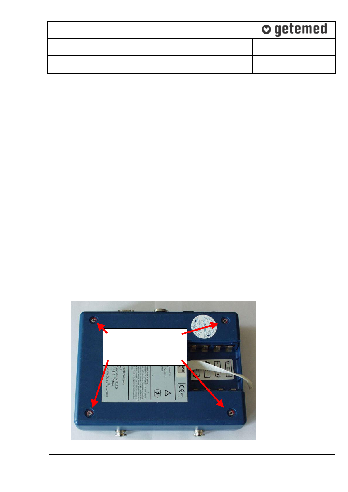
3.3.01
Remove housing screws
3.3.01 Remove the rubber feet and open the housing.
9204-TD-0013-Rev B-Service-Replacement of Internal Battery.doc
CONFIDENTIAL AND PROPRIETY
Page 3

Technical Documentation
VitaGuard VG 3000 / VG 2000 / VG 300
Service Documentation - Replacement of Internal Battery
Project ID : 9204H1
Page 3 / 6
3.3.02 When opening the housing, pay attention to the copper strips used to improve electrical
contact between the housing halves.
3.3.02
Pay attention to
the copper stripes
3.3.05
Loosen these 4 screws
3.3.03 To prevent other hardware failures, measure the voltage of the internal back-up battery.
The voltage PWR_BACKUP is measured from positive pole of CT13 against ground. If
the measured voltage is above 3.0V, the back-up battery is good.
3.3.04 Remove jumper JU4 to break the battery circuit.
3.3.05 Loosen the motherboard with a screw driver or socket wrench, depending on how the
main board is fixed to the casing.
3.3.05
Example:
Main board
mounted with
nuts
9204-TD-0013-Rev B-Service-Replacement of Internal Battery.doc
CONFIDENTIAL AND PROPRIETY
Page 4

Technical Documentation
VitaGuard VG 3000 / VG 2000 / VG 300
Service Documentation - Replacement of Internal Battery
Project ID : 9204H1
Page 4 / 6
3.3.06 The main board is connected to the housing with wires soldered to adhesive copper
strips. Remove the self adhesive copper strips from the housing in order to lift the main
board out of the housing.
3.3.06
Copper stripes
3.3.04
Jumper
3.3.07 The buzzer is connected to the motherboard with 2 wires. Unsolder the wires and
carefully raise the motherboard.
3.3.08 While raising the motherboard, pay attention to the keypad connector and remove the
connector.
3.3.07
Buzzer
3.3.08 Connector for
keypad
9204-TD-0013-Rev B-Service-Replacement of Internal Battery.doc
CONFIDENTIAL AND PROPRIETY
Page 5

Technical Documentation
VitaGuard VG 3000 / VG 2000 / VG 300
Service Documentation - Replacement of Internal Battery
Project ID : 9204H1
Page 5 / 6
3.3.09 Heat the outer ends of the solder tabs and lift off the sides. Remove the back-up battery.
3.3.09 Back-up battery with
solder tabs
3.3.10 Solder in a new back-up battery: The positive side of the battery points in the direction of
the keypad connector. Measure the battery to see if voltage is above 3.0 volts.
3.3.10 Measure voltage
3.3.11 Reconnect the keypad connector to the main board. Solder the buzzer wires back to the
solder pads on the main board.
3.3.12 Fit the main board back into the casing and solder the wires to new self adhesive copper
strips. Stick these onto the housing corners.
3.3.13 Prior to tightening the main board, align the display so that it is straight.
9204-TD-0013-Rev B-Service-Replacement of Internal Battery.doc
CONFIDENTIAL AND PROPRIETY
Page 6

Technical Documentation
consumption
VitaGuard VG 3000 / VG 2000 / VG 300
Service Documentation - Replacement of Internal Battery
Project ID : 9204H1
Page 6 / 6
3.3.14 Measure the current consumption at jumper JU 4. The measured value should be less
than 30 µA.
3.3.14 Measure current
3.3.15 Attach jumper JU 14 again and secure it with silicone adhesive.
3.3.16 Visually inspect soldered wires, mounting of the main board and, where appropriate, the
Masimo board. Check the position of wires and flat cables to other components and
housing. Make sure nothing is pinched or torn off.
3.3.17 The copper strips must be clamped securely before the housing is closed.
3.3.18 If both housing parts fit closely together, insert and tighten the housing screws.
3.3.19 Stick new rubber feet on the screws.
4 Functional check:
4.1 Remove the alkaline batteries from the battery compartment and then remove power
adapter during device operation. Ensure that the device outputs a permanent warning
tone. If the test is not passed, replace C7 according to “9204-TD-0014-Rev A-ServiceReplacement of Capacitor C7”.
4.2 Test the device according to work procedure AA30.
Please forward getemed a copy of the protocol together with the Maintenance Declaration so
that we can update our device database.
9204-TD-0013-Rev B-Service-Replacement of Internal Battery.doc
CONFIDENTIAL AND PROPRIETY
 Loading...