

Getemed VitaGuard 300, VitaGuard 310, VitaGuard 2000, VitaGuard 2100, VitaGuard 3000 Test procedure
...Page 1
Page 2
Service Manual - Test Procedure
VitaGuard®
Projekt ID: 0027
VG 3100 / VG 2100 / VG 310
8 Equipment and Materials
The equipment listed below marked R is the equipment used by getemed AG. Similar
models from other manufacturers can be used as long as the performance is similar.
The model numbers of the equipment listed with getemed AG as manufacturer
correspond with the ordering (REF) numbers, should the distributor wish to purchase
the equipment from getemed.
Equipment Model / REF Manufacturer
Power adapter NA 3000-2 7344 1101 getemed AG
ECG patient cable 7341 1001 getemed AG
Masimo SpO2 cable PC08 70257 getemed AG, Masimo
Masimo SpO2 Sensor DC I 70254 getemed AG, Masimo
PC Interface cable (USB-Kabel) 7341 2001 getemed AG
VitaWin software VitaWin 3 getemed AG
R 1A / 3-6V power supply HM7042 Hameg
R Digital Multimeter Model 87 Fluke
R ECG/Respiration patient simulator 214B DNI Nevada Inc.
R SpO2 patient simulator Oxitest Plus DNI Nevada Inc.
R Stop watch - R Safety tester Unimet 1000 ST Bender
R Test PC with Windows 2000 or XP - -
0027-TD-0027-Rev C
9 Procedure
The procedure is divided into 4 sections:
· Visual inspection of the monitor
· Functional measurements
· Safety inspection
· Visual inspection of accessories
For easy reference, the numbers of this procedure correspond with the numbers in
the test report.
Before beginning the test procedure, the revision stand of the monitor should be
checked. The distributor should contact getemed on a regular basis at
service@getemed.de in order to determine if changes are necessary.
Should the monitor under test show any signs of malfunction, then it must be returned
immediately to getemed AG for inspection.
The test reports must be archived for at least 10 years and made available to
getemed AG on request.
The distributor shall maintain a database showing when a monitor was last tested and
by whom.
The remaining part of section 9 explains how to perform the test procedure. To
correspond with the test report, numbering will begin with 9.7.1.
0027-TD-0027-Rev C-B5.1-Service Manual 18 Month Regular Inspection Test Procedure English.doc
Page 2 of 11
Page 3
Service Manual - Test Procedure
VitaGuard®
Projekt ID: 0027
VG 3100 / VG 2100 / VG 310
9.7.1 Visual inspection of the monitor
The first section of the test report is the visual inspection of the monitor.
9.7.1-1 Labels
All three labels listed in box 1 must be readable and free from damage. If this is the
case, then box 1 can be ticked-off with o.k.
The following labels are readable and not damaged:
· Top label with keys (key panel)
1
· Label on the back of the monitor with serial number and
safety warnings; warning label in battery compartment.
· Label stripe at the front marking all inputs
9.7.1-2 Connectors
The connectors listed in box 2 must be fitted tightly. The connector pins must be
visually inspected to ensure that none of them are damaged. If this is the case, then
box 2 can be ticked-off with o.k.
The following connectors are fitted tightly and not damaged:
· ECG input (VG 3100 and VG 2100 only)
· NA 3000-2 power supply input
2
· SpO2 input (VG 3100 and VG 310 only)
· USB input
· AUX input
9.7.1-3 Casing and LCD display
0027-TD-0027-Rev C
o.k.
o.k.
The monitor casing must not be cracked or have any significant scratches. The LCDdisplay must also be free from damage. If this is the case, then box 3 can be tickedoff with o.k.
3 The monitor casing and the LCD display are not damaged. o.k.
9.7.2 Functional measurements
The second section of the test report involves measuring parameters and performing
functional tests.
The external power adapter NA 3000-2 used must be modified to measure the current
flowing to the monitor. To do this, cut the positive wire going to the monitor and attach
two 4 mm connector jack plugs to the loose ends. These can then be inserted into a
multimeter.
It is assumed that the default settings are selected before beginning the test
procedure.
0027-TD-0027-Rev C-B5.1-Service Manual 18 Month Regular Inspection Test Procedure English.doc
Page 3 of 11
Page 4
Service Manual - Test Procedure
VitaGuard®
Projekt ID: 0027
VG 3100 / VG 2100 / VG 310
0027-TD-0027-Rev C
VitaGuard
Monitor
Comp.
Battery
Digital-
Multimeter
(1)
Power supply
3-6V / 2A
Digital-
Multimeter
NA 3000-2
SpO2Sensor
and
simulator
(3)
SpO2 ECG
Power
AUX
(4)
Patient
simulator
(2)
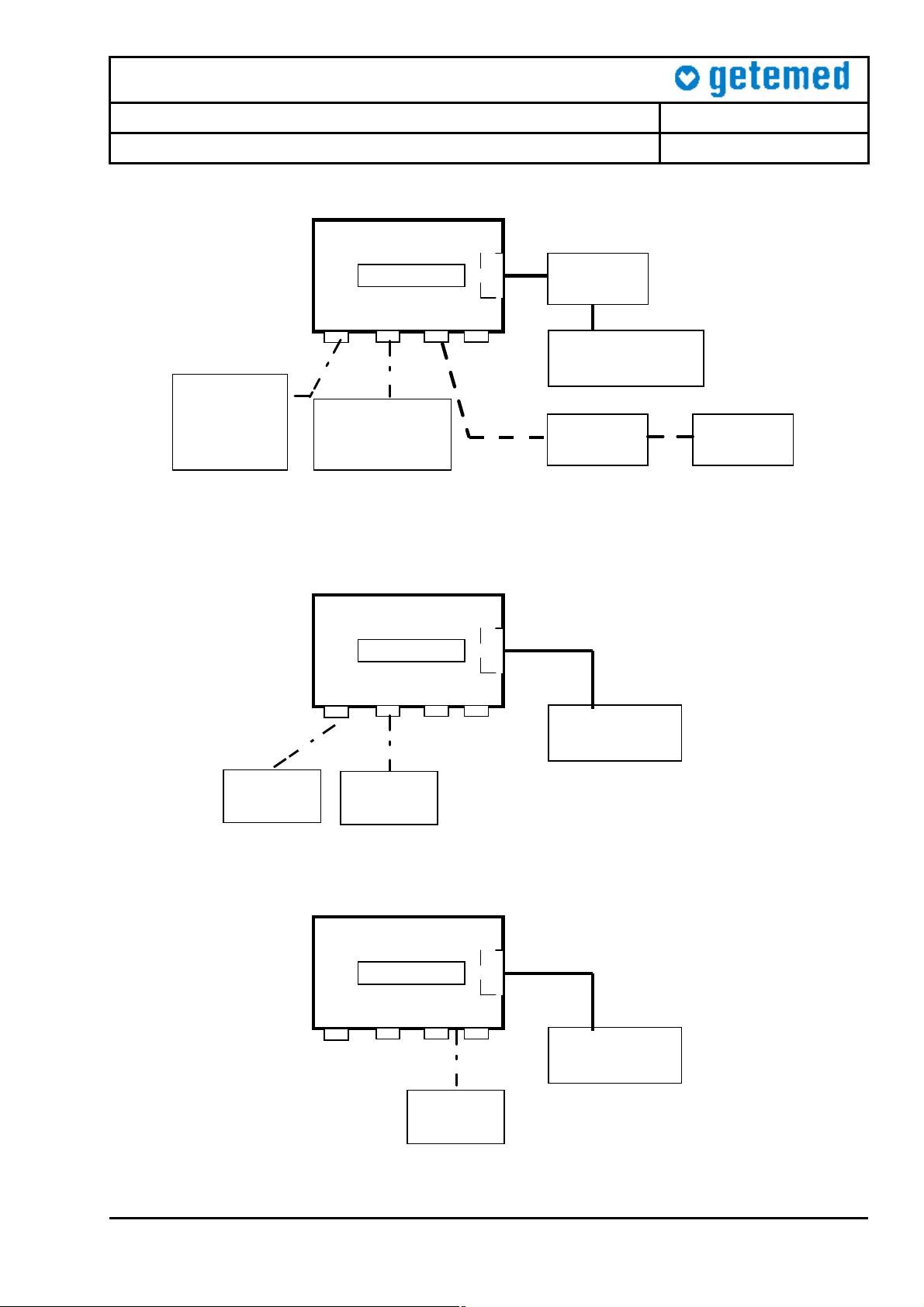
Figure 1 – Current Measurement Set-Up
VitaGuard
Monitor
Battery
Comp.
SpO2 ECG Power
AUX
Power supply
3-6V / 1A
SpO2
Simulator
PatientSimulator
Figure 2 – Alarm Measurement Set-Up
VitaGuard
Monitor
Battery
Comp.
SpO2 ECG
USB
Power AUX
Power supply
3-6V / 1A
PC
VitaWin
Figure 3 – PC Measurement Set-Up
0027-TD-0027-Rev C-B5.1-Service Manual 18 Month Regular Inspection Test Procedure English.doc
Page 4 of 11
Page 5

Service Manual - Test Procedure
B 3 2 1
VitaGuard®
Projekt ID: 0027
VG 3100 / VG 2100 / VG 310
Power
adapter
UNIMET 1000
VG2100/3100/310
0027-TD-0027-Rev C
LCD
Monitor
A
SpO2
ECG
Pwr
USB
AUX
Figure 4 – Patient Safety Tester
9.7.2-1 Current from batteries when monitor switched off
Connect the monitor as shown in Fig. 1 with NA 3000-2 disconnected. Set the output
voltage of the power supply to 6 V. Read the current flowing through the multimeter
(1) while the monitor is switched off. This value should be less than 200 µA. If this is
the case, then enter the value in the box provided.
1 Current from batteries when monitor switched off < 200 µA
9.7.2-2 Current from batteries when monitor switched on
Connect the monitor as shown in Fig. 1 with NA 3000-2 disconnected. Set the output
voltage of the power supply to 6 V. Switch the monitor on and wait until the standard
display appears. Read the current flowing through the multimeter (1). When testing
VG 3100, read the values with the SpO2 module switched on. Enter the values in the
boxes provided.
2 Current from batteries, when monitor switched on
a VG 2100 40 ... 55 mA
b VG 3100, (SpO2 on) 60 ... 83 mA
c (from SN 80105050395) VG 310, (SpO2 on) 55 ... 63 mA
d (from SN 801040001 to SN 801050394) VG 310, (SpO2 on) 60 ... 75 mA
9.7.2-3 Current from batteries when NA 3000-2 connected
Connect the monitor as shown in Fig. 1. Connect the external power adapter NA
3000-2 to the monitor and read the current flow through multimeter (1). Enter the
value in the box provided.
3 Current from battery when NA 3000-2 connected < 5 µA
0027-TD-0027-Rev C-B5.1-Service Manual 18 Month Regular Inspection Test Procedure English.doc
Page 5 of 11
Page 6

Service Manual - Test Procedure
VitaGuard®
Projekt ID: 0027
VG 3100 / VG 2100 / VG 310
0027-TD-0027-Rev C
9.7.2-4 Current from NA 3000-2 when monitor switched off
Connect the monitor as shown in Fig. 1. Switch the monitor off and read the current
flowing through multimeter (2). Enter the value in the box provided.
4 Current from NA 3000-2 when monitor switched off 4,5 ... 6 mA
9.7.2-5 Current from NA 3000-2 when monitor switched on
Connect the monitor as shown in Fig. 1. Switch the monitor on and wait until the
standard display appears. Read the current flowing through multimeter (2). When
testing VG 3100 ensure that the SpO2 module is switched on. Enter the values in the
boxes provided.
5 Current from NA2000-2, when monitor switched on
a VG 2100 107 ... 125 mA
b VG 3100, (SpO2 on) 125 ... 140 mA
c (from SN 80105050395) VG 310, (SpO2 on) 120 ... 128 mA
d (from SN 801040001 to SN 801050394) VG 310, (SpO2 on) 125 ... 135 mA
9.7.2-6 Green power LED
Connect the monitor as shown in Fig. 1. When the external adapter NA 3000-2 is
connected, the green power LED on the monitor front panel must illuminate. This
must happen when the monitor is switched on or off.
6 Green LED lights when NA 3000-2 connected o.k.
9.7.2-7 LCD backlight
Connect the monitor as shown in Fig. 1. When the external adapter NA 3000-2 is
connected and the monitor is switched on, the LCD backlight must illuminate. Ensure
that the brightness setting is > 70%
7 LCD backlight switches on when NA 3000-2 connected o.k.
9.7.2-8 Switch-over between NA 3000-2 and batteries
Connect the monitor as shown in Fig. 1. When the external adapter NA 3000-2 is
connected, the monitor switches automatically away from the batteries. When the
adapter is disconnected, the monitor switches back to battery mode. To perform the
test, remove and reconnect the adapter 3 times at the connector input in short
succession. The monitor must operate normally throughout the test. If this is the case,
enter o.k. in the box provided.
8 Automatic change-over between batteries and NA 3000-2 o.k.
9.7.2-9 Switch-over between NA 3000-2 and batteries
Connect the monitor as shown in Fig. 1. Repeat the test above. This time remove the
external adapter NA 3000-2 from the socket. The monitor must operate normally
throughout the test. If this is the case, enter o.k. in the box provided.
9 Automatic change-over when NA 3000-2 pulled from socket o.k.
0027-TD-0027-Rev C-B5.1-Service Manual 18 Month Regular Inspection Test Procedure English.doc
Page 6 of 11
Page 7

Service Manual - Test Procedure
VitaGuard®
Projekt ID: 0027
VG 3100 / VG 2100 / VG 310
0027-TD-0027-Rev C
9.7.2-10 Battery symbol full
Remove the NA 3000-2 adapter and power the monitor from the Hameg power
supply, as shown in Fig. 1. Set the output voltage to 6 V. The battery symbol in the
status line must be full i.e. completely black. If this is the case, then enter o.k. in the
box provided.
10 Battery symbol full 6.0V
9.7.2-11 Battery symbol empty
Remove the NA 3000-2 adapter and power the monitor from the Hameg power
supply, as shown in Fig. 1. Set the output voltage to 4.1 V. The battery symbol in the
status line must be empty. If this is the case, then enter o.k. in the box provided.
11 Battery symbol empty
4.6 V ± 0.2V
9.7.2-12 Internal battery
Check the state of the internal battery by looking at Info window 2. The message must
read “very good”. If this is the case, then enter o.k. in the box provided.
12 Internal battery “very good” o.k.
9.7.2-13 Data retention
Connect the monitor as shown in Fig. 2. Set the apnea pause time to 12 s and the
lower heart rate to 60 /min. Switch the monitor off and back on again. These values
must reappear.
13 Parameters stay stored when monitor switched off o.k.
9.7.2-14 System LED’s
Connect the monitor as shown in Fig. 2. Switch the monitor off and back on again.
During the start-up phase, all LED’s must illuminate.
14 LED’s activated upon start-up, LCD display o.k. o.k.
9.7.2-15 System alarm buzzer
Connect the monitor as shown in Fig. 2. Switch the monitor off and back on again.
During the start-up phase, the system buzzer must sound loud and clear.
15 Buzzer sounds loud and clear o.k.
9.7.2-16 Apnea alarm
Set the apnea pause time to 12 s. Let the monitor run for 1 minute. Do not press any
keys during this time. Provoke an apnea alarm on the ECG patient simulation (4)
shown in Fig. 2. The monitor must respond with an apnea alarm within 12 s ± 2 s.
16 Apnea alarm after 12 s 10 … 14 s
0027-TD-0027-Rev C-B5.1-Service Manual 18 Month Regular Inspection Test Procedure English.doc
Page 7 of 11
Page 8

Service Manual - Test Procedure
VitaGuard®
Projekt ID: 0027
VG 3100 / VG 2100 / VG 310
0027-TD-0027-Rev C
9.7.2-17 Apnea alarm
Connect the monitor as shown in Fig. 2. Let the apnea alarm continue for a further 15
seconds once the monitor has begun to alarm. The alarm must stay active for the
complete duration. Do not press any keys during this test.
17 Apnea alarm stays active for further 15 s o.k.
9.7.2-18 Basal impedance = 500 Ohm
Connect the monitor as shown in Fig. 2. Set the basal impedance on the patient
simulator to 500 W and, using the info windows, note the value for the basal
impedance measured. Ensure that lead YE-RD is selected.
18
Basal impedance = 500 W 400 ... 600 W
9.7.2-19 Basal impedance = 1000 Ohm
Connect the monitor as shown in Fig. 2. Set the basal impedance on the patient
simulator to 1000 W and, using the info windows, note the value for the basal
impedance measured.
19
Basal impedance = 1000 W 900 ... 1100 W
9.7.2-20 Open-Lead warnings
Connect the monitor as shown in Fig. 2. Disconnect the red electrode from the patient
cable. The corresponding open-lead warning message must appear on the LCD
display accompanied by a technical alarm. Do not press any keys during this test.
20 Warning when electrode removed o.k.
9.7.2-21 Heart rate display
Connect the monitor as shown in Fig. 2. Set the lower heart rate limit to 60 /min and
the upper limit to 200 /min. Using the patient simulator, increase the heart rate from
30 to 240 /min in appropriate steps. Ensure that the same heart rate is displayed on
the monitor.
21 Heart rate from 30 – 240 /min
HR ± 2 /min
9.7.2-22 Lower heart rate alarm
Connect the monitor as shown in Fig. 2. Using the patient simulator, set the heart rate
to 40 /min. Once the displayed HR falls below 60 /min, note the time for a bradycardia
alarm to appear. Do not press any keys during this test.
22 Bradycardia alarm when HR = 40 /min 4 ... 8 s
9.7.2-23 Upper heart rate alarm
Connect the monitor as shown in Fig. 2. Using the patient simulator, set the heart rate
to 240 /min. Once the displayed HR increases above 200 /min, note the time for a
tachycardia alarm to appear. Do not press any keys during this test.
23 Tachycardia alarm when HR = 240 /min 13 … 17 s
0027-TD-0027-Rev C-B5.1-Service Manual 18 Month Regular Inspection Test Procedure English.doc
Page 8 of 11
Page 9

Service Manual - Test Procedure
VitaGuard®
Projekt ID: 0027
VG 3100 / VG 2100 / VG 310
0027-TD-0027-Rev C
9.7.2-24 ECG sensitivity
Connect the monitor as shown in Fig. 2. Using the patient simulator, set the ECG
amplitude to 0.5 mV. Ensure that 20 consecutive beats are registered by the monitor
by observing the heart rate LED.
24 Heart rate when signal amplitude = 0.5 mV o.k.
9.7.2-25 No ECG alarm
Connect the monitor as shown in Fig. 2. Switch the patient simulator off and note the
time for the monitor to produce a QRS! alarm. Do not press any keys during this test.
25 Alarm when no signal present 3 ... 5 s
9.7.2-26 SpO2 sensor off warning
Connect the monitor as shown in Fig. 2. Disconnect the SpO2 sensor from the SpO2
simulator. The monitor must display sensor off alarm and produce a technical alarm.
26 Sensor off: Warning and technical alarm o.k.
9.7.2-27 SpO2 measurements
Connect the monitor as shown in Fig. 2. Set the monitor such that the heart rate is
determined from the Masimo SpO2 module (SpO2 menu). Set the pulse rate of the
SpO2 simulator to 100 /min. Select 4 SpO2 values from the simulator and verify that
these values are displayed by the monitor.
27 SpO2 set to 86%, 90%, 94%, 98% with HR = 100 /min o.k.
9.7.2-28 Pulse rate measurements
Connect the monitor as shown in Fig. 2. Set the SpO2 simulator to 96%. Select 4
pulse rate values from the simulator and verify that these values are displayed by the
monitor.
28 HR set to 70, 100, 150, 200 /min with SpO2 = 96% o.k.
9.7.2-29 SpO2 low alarm
Connect the monitor as shown in Fig. 2. Set the lower SpO2 limit to 88% and the
upper SpO2 limit to 98%. Let the monitor operate for 1 minute. Set the SpO2 simulator
to 70%. Verify that an SpO2 alarm occurs within 10s after the displayed value falls
below 88%. Do not press any keys during this test.
29 SpO2 alarm when SpO2 = 70% 8 ... 12 s
9.7.2-30 SpO2 high alarm
Connect the monitor as shown in Fig. 2. Set the lower SpO2 limit to 88% and the
upper SpO2 limit to 98%. Let the monitor operate for 1 minute. Set the SpO2 simulator
to 100%. Verify that an SpO2 alarm occurs within 10 s after the displayed value rises
above 98%. Do not press any keys during this test.
30 SpO2 alarm when SpO2 = 100% 8 ... 12 s
0027-TD-0027-Rev C-B5.1-Service Manual 18 Month Regular Inspection Test Procedure English.doc
Page 9 of 11
Page 10

Service Manual - Test Procedure
VitaGuard®
Projekt ID: 0027
VG 3100 / VG 2100 / VG 310
9.7.2-31 Alarm episodes
Connect the monitor as shown in Fig. 3 and activate the VitaWin software on the PC.
Download the alarm episodes stored in the monitor during testing. Examine the data
to ensure that the signals have no interference. Also, check that the time stamp is
correct. If not, set the time/date on the device.
31 Read and analyse stored episodes o.k.
9.7.2-32 Compliance protocol
Connect the monitor as shown in Fig. 3 and activate the VitaWin software on the PC.
Download the compliance protocol and examine the data.
32 Read compliance protocol o.k.
9.7.2-33 Monitor reset
Reset the monitor by executing the “Admit New Patient” function
33 Reset monitor o.k.
9.7.3 Safety inspection
0027-TD-0027-Rev C
Connect the monitor to the patient safety tester as shown in Fig. 4. Most testers
perform the tests automatically and print out a protocol. This protocol can be attached
to the test report.
The tests performed should conform to EN 60601-1, class II, CF (cardiac floating).
9.7.4 Visual inspection of accessories
All the monitor accessories must be visually inspected before use. Special care must
be taken to ensure that all cables and connectors are clean and free from damage.
Any damaged accessories must be replaced. The user manual and the packaging
must also be clean.
Nr
Measurement / Action Range Value
1 Visual inspection of ECG cable o.k.
2 Visual inspection of power adapter NA 3000-2 o.k.
3 Visual inspection of SpO2 cable (PC08 or PC12) o.k.
4 Visual inspection of user manual o.k.
5 Visual inspection of packaging o.k.
0027-TD-0027-Rev C-B5.1-Service Manual 18 Month Regular Inspection Test Procedure English.doc
Page 10 of 11
Page 11

Service Manual - Test Procedure
VitaGuard®
Projekt ID: 0027
VG 3100 / VG 2100 / VG 310
9.8 Analysis and recommendations
Upon completing the tests, the results must be summarised in the table below. Any
comments or recommendations must be documented.
Part Result Recommendation
7.1
7.2
7.3
7.4
Finally, the test engineer must check the appropriate box below, declaring whether
the monitor is suitable for further use or not.
Monitor suitable for further use: yes o no o
10 Acceptance Criteria
0027-TD-0027-Rev C
The measured values must be documented in the test report provided and the results
analysed. Any results not meeting the requirements listed are to be assessed for their
potential effect. The monitor can only be accepted for further use if all the measured
values are within their allowed tolerances. If any deviations have been detected, the
distributor must inform getemed AG. It will then be decided if the monitor should be
returned to getemed AG for inspection.
0027-TD-0027-Rev C-B5.1-Service Manual 18 Month Regular Inspection Test Procedure English.doc
Page 11 of 11
 Loading...