

Page 1
VitaGuard® VG 310
Pulse oximeter
Operating instructions
Page 2

Page 3

Who should read which sections in these
operating instructions?
The sections 3 to 7 colored blue at the top of the page and in
the table of contents are intended specifically for caregivers
without medical background knowledge.
The other sections are intended in particular for doctors and
qualified medical staff.
1 General view and list of accessories
2 Intended use
3 Safety
4 Description
5 Steps before and after monitoring
6 Preparing for SpO2 monitoring
7 Alarms, displays, and views during monitoring
8 Alarm and monitor settings
9 Information for the doctor and qualified medical staff
10 Algorithms and measuring principles
11 Evaluating stored data on a PC
12 Specifications
13 Table of figures
NOTE Words and passages in small capitals in these operating
instructions also appear on the display.
Page 4

Page 5

Table of contents
Table of contents
1 General view and list of accessories ...................................... 11
2 Intended use .......................................................................................... 14
2.1 Label on the back of the device .............................................................. 14
2.2 Symbols and warnings .............................................................................. 14
2.3 Indications .................................................................................................... 16
2.4 Intended use and performance .............................................................. 16
2.5 Limitations on VitaGuard®’s intended use ......................................... 17
2.6 Information for the doctor on these operating instructions ......... 17
3 Safety .......................................................................................................... 18
3.1 Caregivers’ tasks ......................................................................................... 18
3.2 Allergy risks to patients ............................................................................ 19
3.3 Possible external interference to monitoring .................................... 20
3.3.1 Installation and environment ................................................ 20
3.3.2 Noise risks to monitoring ........................................................ 21
3.3.3 Electrostatic interference ........................................................ 21
3.3.4 Electromagnetic interference ................................................. 21
3.4 Safety with approved accessories only ................................................ 23
3.5 Handling patient cables ........................................................................... 23
3.6 Power supply reliability ............................................................................ 24
3.6.1 Battery voltage indicator ......................................................... 25
3.6.2 Interruptions to the power supply ........................................ 26
3.6.3 Using the rechargeable block battery .................................. 26
3.7 Safety with proper maintenance only .................................................. 27
3.7.1 Cleaning VitaGuard® and accessories ................................. 27
3.7.2 Checking and cleaning the battery terminals ................... 28
3.8 Disposing of non-rechargeable batteries, the device, and
accessories .................................................................................................... 29
4 Description .............................................................................................. 30
4.1 Power supply ................................................................................................ 31
4.1.1 Power failure with inserted batteries .................................. 32
4.1.2 Power failure without batteries ............................................ 32
4.1.3 Replacing batteries .................................................................... 33
4.1.4 Using the automobile power supply adapter .................... 34
Page 6

Table of contents
4.2 VitaGuard® connections .......................................................................... 35
4.2.1 Patient cable for SpO2 sensors ............................................... 35
4.2.2 Power adapter ............................................................................. 36
4.2.3 Sound outlet (no socket) .......................................................... 36
4.2.4 USB port ........................................................................................ 37
4.2.5 AUX port ....................................................................................... 37
4.3 Membrane key panel ................................................................................ 38
4.3.1 Direction keys .............................................................................. 39
4.3.2 <Enter> key ................................................................................... 39
4.3.3 <Esc> key ....................................................................................... 39
4.4 Color LEDs (Light Emitting Diodes) ....................................................... 40
4.4.1 Alarm LED ..................................................................................... 40
4.4.2 Heart LED ...................................................................................... 40
4.4.3 Power supply and battery LEDs ............................................. 41
4.5 The display ................................................................................................... 41
5 Steps before and after monitoring ......................................... 43
5.1 Summary of steps before monitoring .................................................. 43
5.2 Switching on ................................................................................................ 43
5.3 Switching off ............................................................................................... 44
5.4 Summary of steps after monitoring ..................................................... 45
6 Preparing for SpO2 monitoring ................................................. 46
6.1 Safety instructions for SpO2 monitoring ............................................. 46
6.2 Operation of SpO2 sensors ...................................................................... 47
6.3 SpO2 sensor adapted to the patient’s size and weight ................... 48
6.4 Choosing the sensor site .......................................................................... 48
6.5 Repositioning or replacing the sensor ................................................. 49
6.6 Reasons for unconvincing SpO2 values ................................................ 49
6.7 Why the pulse rate is not displayed ..................................................... 50
6.8 Attaching the SpO2 sensor to an infant’s foot .................................. 50
6.9 Attaching the SpO2 sensor to an adult’s finger ................................ 51
6.10 Connecting the SpO2 sensor and patient cable ................................ 53
6.11 Connecting the SpO2 patient cable to VitaGuard® .......................... 53
6.12 Disconnecting the SpO2 sensor from the patient cable ................. 54
6.13 Disconnecting the SpO2 patient cable from VitaGuard® ............... 54
6.14 Reusing and refastening SpO2 sensors ................................................ 54
Page 7

Table of contents
7 Alarms, displays, and views during monitoring ............ 56
7.1 Alarm test ..................................................................................................... 56
7.2 Pulse rate values based on age groups .............................................. 56
7.3 Alarm message priorities in the status line ........................................ 57
7.4 Physiological and technical alarms ....................................................... 57
7.5 Differentiating physiological and technical alarm signals ............ 58
7.6 Acoustic information signals .................................................................. 58
7.6.1 Information signals from the alarm unit next
to the display ............................................................................... 59
7.6.2 Information signals from the sound aperture
between the sockets ................................................................. 59
7.7 The visual alarm signals ........................................................................... 59
7.8 Status line displays .................................................................................... 59
7.9 SpO2 monitor alarms ................................................................................ 60
7.9.1 Physiological SpO2 alarms ....................................................... 60
7.9.2 Technical SpO2 alarms .............................................................. 61
7.10 Pulse rate alarms ........................................................................................ 61
7.11 Alarm messages – meanings and other information ...................... 62
7.11.1 Order of equal-priority alarm conditions ............................ 62
7.11.2 Table of physiological alarm messages ............................... 62
7.11.3 Table of technical alarm messages ....................................... 64
7.12 Table of information messages .............................................................. 66
8 Alarm and monitor settings ........................................................ 67
8.1 Safety instructions for the alarm settings .......................................... 67
8.2 Summary of views and menus ............................................................... 68
8.3 Additional views ......................................................................................... 68
8.3.1 View 2 – Large data presentation and waveforms .......... 69
8.4 Changing the settings ............................................................................... 69
8.5 System menu – general settings ............................................................ 70
8.5.1 \ Screen saver (Off/ On) ......................................................... 71
8.5.2 \LCD brightness ....................................................................... 71
8.5.3 \LCD contrast ........................................................................... 71
8.5.4 \ Signal beep tone ..................................................................... 71
8.5.5 \ Alarm tone pitch .................................................................... 72
8.5.6 \RS232 format ........................................................................... 72
Page 8

Table of contents
8.5.7 \ Settings protection On, Limited, Off ............................. 72
8.6 SpO2 display and menu ............................................................................ 73
8.6.1 SpO2 view ..................................................................................... 74
8.6.2 SpO2 menu – alarm settings (Settings
protection Limited) .................................................................. 75
8.7 Pulse rate display and menu ................................................................. 76
8.7.1 Pulse rate display ...................................................................... 76
8.7.2 Pulse rate menu – alarm settings (Settings
protection Limited) .................................................................. 76
9 Information for the doctor and qualified
medical staff
9.1 Safety instructions ..................................................................................... 78
9.1.1 Preparing for a new patient .................................................... 78
9.1.2 Connections to the USB and AUX ports .............................. 79
9.1.3 VitaGuard® and other medical devices ............................... 80
9.1.4 Safety instructions for the doctor – SpO2 monitor .......... 81
9.2 Info display .................................................................................................. 81
9.2.1 \ Last status messages ............................................................ 82
.......................................................................................... 78
9.2.2 \ General ...................................................................................... 82
9.2.3 \ Measurements: SpO2 ............................................................ 83
9.2.4 \ Measurements: Pulse rate ................................................. 84
9.2.5 \ Settings: Oximeter ................................................................ 84
9.2.6 \ Settings: Pulse rate .............................................................. 85
9.2.7 \ Memory/ Internet ................................................................. 85
9.2.8 \Versions .................................................................................... 85
9.3 Settings in the System menu (Settings protection Off) .............. 86
9.3.1 Changing multiple-component settings ............................ 86
9.3.2 \Operating area: Home or Clinic ......................................... 87
9.3.3 \Admit new patient – restoring factory settings ........... 87
9.3.4 \Pre- and Post-alarm time .................................................... 89
9.3.5 \ Alarm mute time .................................................................... 89
9.3.6 \Date/time ................................................................................. 90
9.3.7 \ Language .................................................................................. 90
9.3.8 \Analog input 1 + 2 ................................................................ 90
9.3.9 \ Interval recording ............................................................... 90
Page 9

Table of contents
9.4 Data storage functions ............................................................................. 90
9.5 Event storage .............................................................................................. 91
9.5.1 Silent alarm limits ................................................................... 93
9.5.2 Manual data storage or Transmit data .......................... 93
9.5.3 Summary of stored Events ...................................................... 94
9.6 Trend storage .............................................................................................. 95
9.7 Long term storage over eight hours .................................................... 95
9.8 Protocol storage of operating and device data ............................... 95
9.9 Summary of stored signals and data .................................................... 96
9.10 Settings in the SpO2 menu (Settings protection Off) ................... 97
9.11 Settings in the Pulse rate menu (Settings protection Off) ....... 99
10 Algorithms and measuring principles ..................................102
10.1 Alarm condition and report delays ........................................................102
10.2 Alarm report delays ....................................................................................102
10.3 Measuring principle for the SpO2 monitor .........................................103
11 Evaluating stored data on a PC .................................................107
12 Specifications ........................................................................................109
12.1 General ..........................................................................................................109
12.2 SpO2 and pulse rate monitor ..................................................................111
12.3 Intervals for calculating average values in the Info mask .............112
12.4 Memory .........................................................................................................112
12.5 Ports ................................................................................................................113
12.6 Miscellaneous ..............................................................................................113
12.7 Selection of applied standards ...............................................................114
13 Table of figures .....................................................................................115
Page 10

Table of contents
Page 11
General view and list of accessories 11
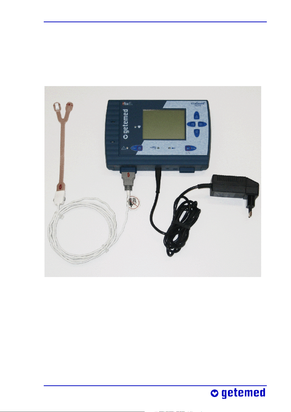
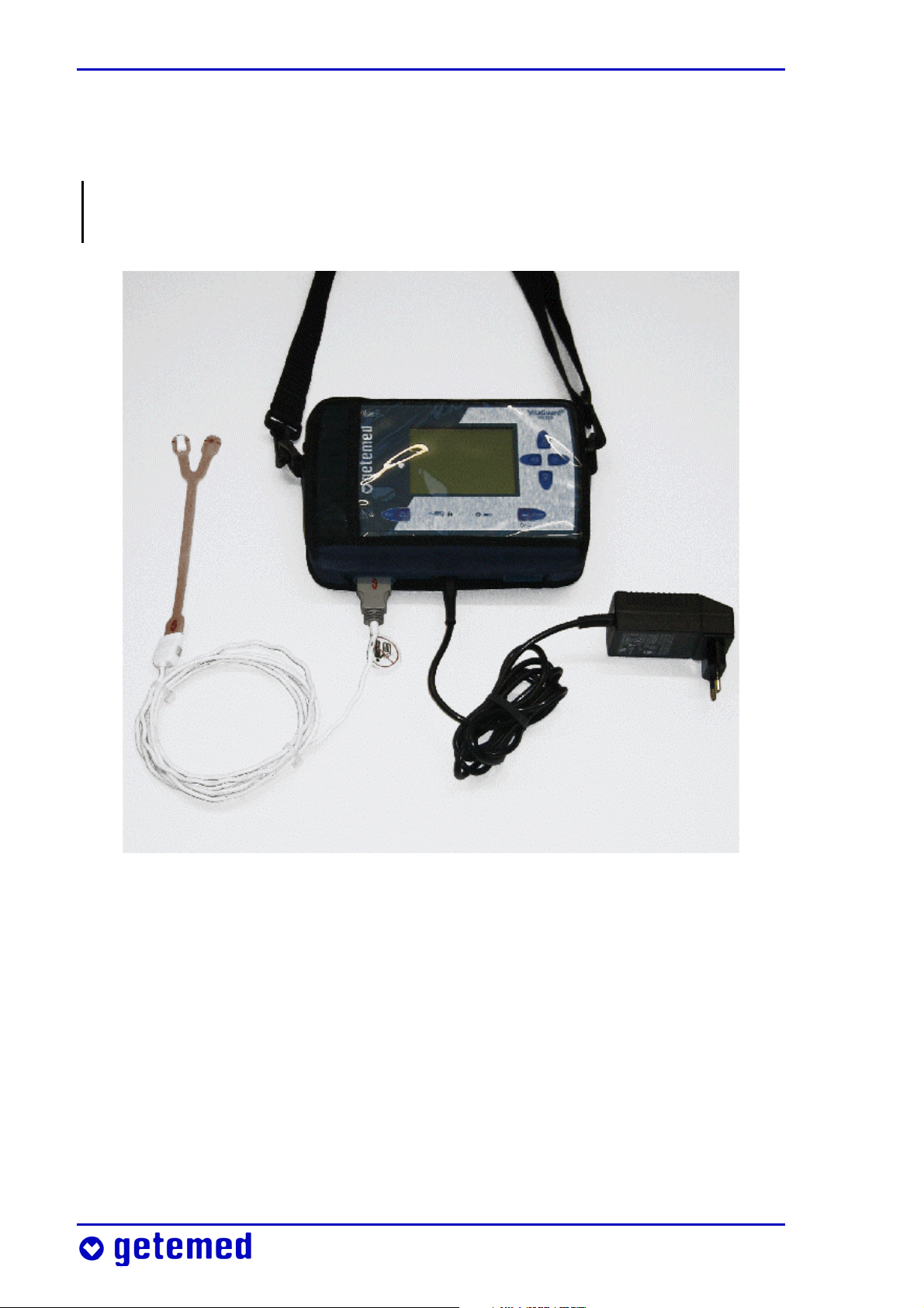
1 General view and list of accessories
The general view shows the monitoring system’s most important
components.
SpO
2
sensor
SpO
2
cable
patient
VitaGuard®
monitor
External
power adapter
Fig. 1 General view of the monitoring system
The accessories listed in the following can be used together with
VitaGuard® and can be ordered with the specified article numbers
from getemed AG or authorized dealers. Please consult getemed AG
or your authorized dealer for other approved accessories.
Page 12

12 General view and list of accessories
Product ........................................................................................ Article no. / REF
VitaGuard® VG 310 Monitor (with Masimo SET®),
complete system ............................................................................... 7311 3022
1 VitaGuard® VG 310 monitor
1 SpO2 patient cable PC08
1 SpO2 LNOP Neo sensor incl. spare adhesive strip
1 NA3000-2 external power adapter
1 rechargeable block battery
1 device bag
1 operating instructions, 1 quick reference
Transport case
NA 3000-2 external power adapter
(110 V–240 V~ / 50–60 Hz) ............................................................... 7344 1101
NAK 3000-2 automobile power supply adapter .................... 7344 1201
Rechargeable block battery ........................................................... 7344 2201
Masimo SpO2 patient cable PC08 (2.44 m) ...................................... 70257
Masimo LNOP® NeoPt SpO2 sensor (PU = 20 pcs)
(for one patient use only, infants < 1 kg) .......................................... 70250
Masimo LNOP® Neo SpO2 sensor (PU = 20 pcs)
(for one patient use only, infants < 10 kg) ........................................ 70251
Masimo LNOP® Pdt SpO
sensor (PU = 20 pcs)
2
(for one patient use only, pediatric/ slender finger 10–50 kg) . 70252
Masimo LNOP® Adt SpO
sensor (PU = 20 pcs)
2
(for one patient use only, adult > 30 kg) ........................................... 70253
Masimo LNOP® DCI reusable sensor (> 30 kg) ................................ 70254
Masimo LNOP® DCIP reusable sensor (10–50 kg) .......................... 70264
Other models are available in addition to the SpO2 sensors listed here.
Page 13

General view and list of accessories 13
Operating instructions (English) ................................................ 7381 3021
Alarm chart (English) ..................................................................... 7383 1021
Device bag ........................................................................................ 7345 1001
VitaGuard® transport case (for the complete system) ........ 7391 0001
AUX 01 RS232 cable for connecting VitaGuard®
to a serial PC port ............................................................................ 7341 2002
AUX-02 modem cable for connecting a
modem to VitaGuard® .................................................................. 7341 3001
AUX-03 cable for connecting an external alarm unit
to VitaGuard® ................................................................................ 7341 5001
AUX-04 cable for connecting VitaGuard®
to a nurse call system with 4 kV isolation ............................... 7341 5011
AUX-06 cable for connecting two external signal sources
to VitaGuard® .................................................................................. 7341 6001
Page 14
14 Intended use
2 Intended use
This section provides information on the intended use of VitaGuard®
and the limitations of this intended use.
The doctor treating the patient is responsible for the application of
VitaGuard®. The specific “Information for the doctor and qualified
medical staff” can be found on page 78.
getemed AG recommends qualified training for the caregivers in
potentially necessary resuscitation techniques. Clearing the respiratory tract and the resuscitation of babies and infants require particular know-how that the treating doctor should communicate to the
caregivers.
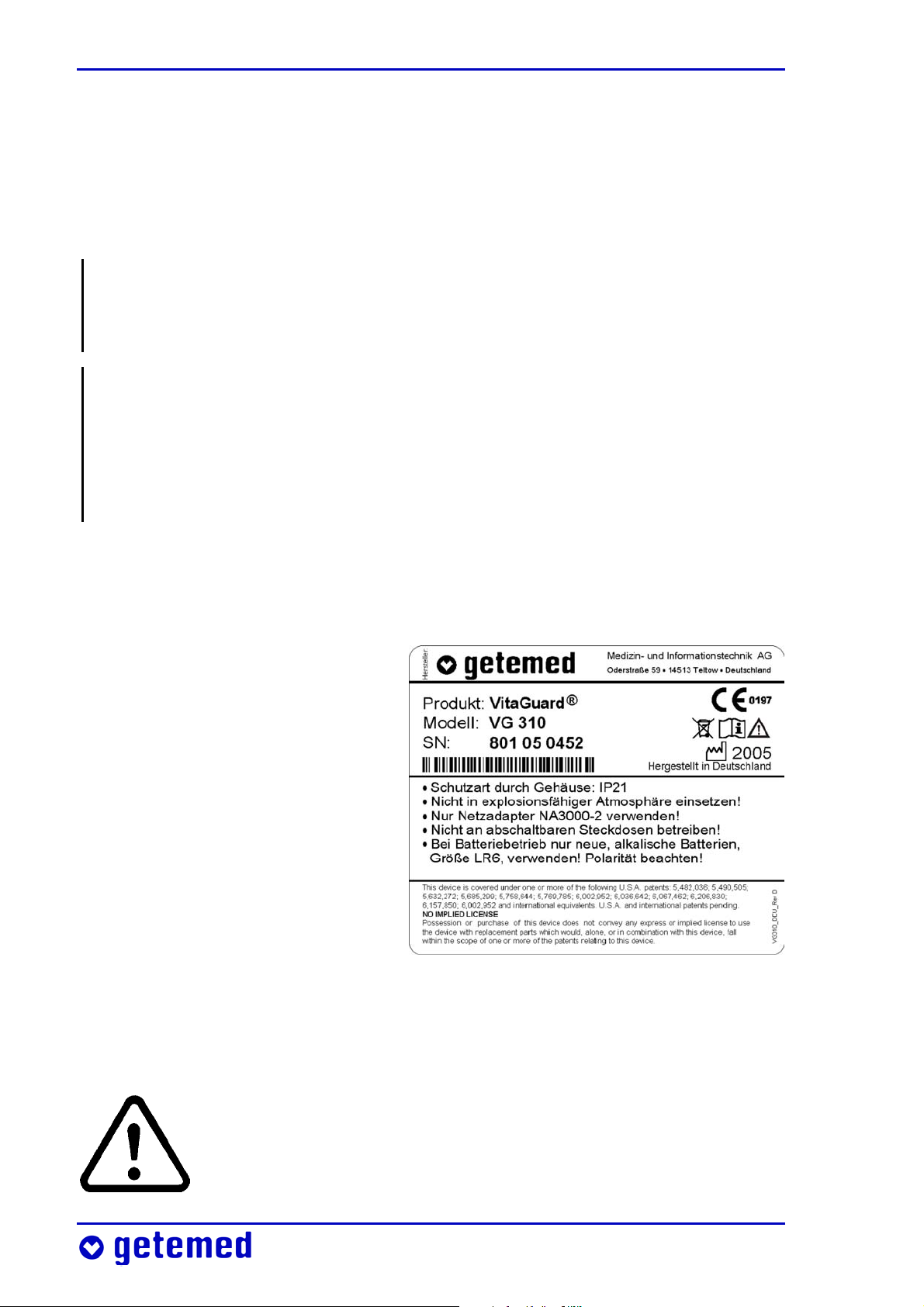
2.1 Label on the back of the device
The device label serves as a
unique identifier for VitaGuard®.
In addition, the label bears important cautionary information.
On the device label you will
find the manufacturer’s name
and address as well as the
product and model name. The
serial number of your device is
given next to SN.
Fig. 2 Device label on the bottom of the device
2.2 Symbols and warnings
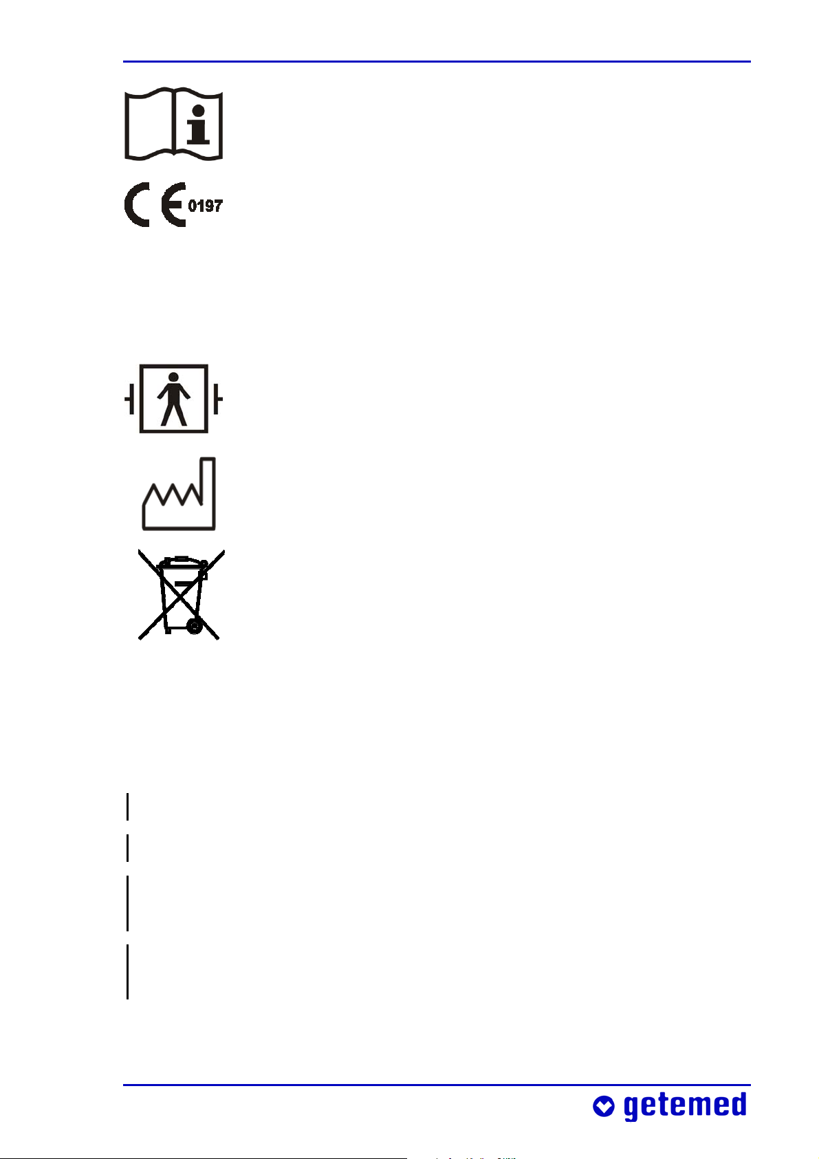
This symbol warns you that failure to observe these operating instructions can cause death or injury to the patient.
Page 15
Intended use 15
The book symbol means that you must not use the device when you are not familiar with the information contained in these operating instructions.
With this CE label and the CE approval number 0197
getemed AG confirms that VitaGuard® complies with all
the pertinent regulations and in particular the requirements in Annex I of the Medical Devices Directive
93/42/EWG and that this has been approved by a notified body (TÜV Rheinland Product Safety).
This symbol means that the VitaGuard®’s SpO
a type BF (body floating) application part that is protected against the effects of defibrillation.
The factory symbol shows the year of manufacture.
Like every electronic device, VitaGuard® and accessories
contain metal and plastic parts that must be disposed of
in such a way that they do not pollute the environment
after their service live. For this reason, the device and accessories may be sent to getemed AG in an adequately
stamped package, when possible in the original packaging, for free and proper disposal.
Note the warnings on the device label.
socket is
2
Do not use in explosive atmospheres!
Use the NA 3000-2 power adapter only!
Warning: Do not connect to an electrical socket controlled by a wall
switch!
Only new alkaline batteries (LR6 or AA) must be used when the
device is powered by non-rechargeable batteries! Note the polarity!
Page 16

16 Intended use
2.3 Indications
The SpO2 and pulse rate monitor with the attached accessories is
suitable for the permanent, non-invasive monitoring of arterial blood
oxygen saturation (SpO
SpO
%SpO
sensor. The functional blood oxygen saturation displayed as
2
is determined exclusively from the measurements of oxygen-
2
ated and deoxygenated hemoglobin. The SpO
) and of the pulse rate as measured with the
2
and pulse rate moni-
2
tor is suitable for adult, pediatric, and infant patients, in mobile or
stationary indoor and outdoor applications
, including patients with
weak blood flow and those in hospitals and other institutions.
2.4 Intended use and performance
The intended use of VitaGuard® is to monitor the pulse rate as well as
the oxygen saturation. VitaGuard® is designed for applications at
home and in rooms used for medical purposes. VitaGuard® has no
therapeutic effect. VitaGuard® emits an acoustic and visual alarm
when the measured pulse rate and/or oxygen saturation values
violate the set alarm limits for a period set by the operator. The alarm
limits can be set within particular values specified by VitaGuard®.
Blood oxygen saturation and pulse rate are monitored with an SpO
2
sensor suitable to the patient’s age and weight. When the signal
registered by the SpO
sensor is inadequate for the reliable meas-
2
urement of values, a message appears on the display.
Physiological data measured for a set period before and after an
alarm are stored and can afterwards be evaluated and documented.
VitaGuard® can be operated with the NA3000-2 power adapter (9 V),
the NAK3000-2 automobile power adapter (e.g. in the cigarette
lighter), four non-rechargeable batteries, or a rechargeable block
battery. Non-rechargeable batteries or the rechargeable block battery
serve above all to safeguard the monitor’s functions during a power
failure and to continue monitoring the heart rate and oxygen saturation when patients are in transit.
Page 17

Intended use 17
2.5 Limitations on VitaGuard®’s intended use
Even when operated in accordance with its intended use, VitaGuard®
cannot detect all life-threatening situations under certain unfavorable conditions.
The monitoring of SpO2 and pulse rate is adversely affected when the
patient moves vigorously or is vigorously moved.
When the sensor is not attached correctly, ambient light can falsify
measurements. One remedy is to cover the sensor with a dark or
opaque material.
The monitor operates properly only when the SpO
attached.
sensor is correctly
2
2.6 Information for the doctor on these
operating instructions
In full knowledge of these operating instructions, the treating doctor must decide:
whether the caregivers have to be trained in the performance of
resuscitation measures,
how the caregivers can be best prepared for monitoring and above
all for the measures that must be taken in the event of an alarm,
which view should be displayed
Information on Settings protection that sets the display modes and
user configurations can be found on page 72.
“Information for the doctor and qualified medical staff” is found on
page 78.
Page 18

18 Safety
3 Safety
The doctor decides whether the caregivers are able to use VitaGuard®
for monitoring and whether they can implement appropriate measures in the event of an alarm.
3.1 Caregivers’ tasks
With “caregivers” we mean those persons who are responsible during
monitoring for the monitored patient’s well-being, for example:
parents or other members of the family,
babysitters, when they too have been thoroughly prepared for the
situation,
nurses and other medically trained staff.
Observe in particular the information in those sections of the operating instructions that, like here, address you directly.
Observe the extensive safety instructions at the beginning of the
section “Preparing for SpO2 monitoring” on page 46.
VitaGuard® has no therapeutic effect. You may have to implement
resuscitation measures in the event of an alarm.
The potential applications of VitaGuard® for high-risk patients are
so many and diverse that we are unable to give any specific instructions on procedure in the event of an alarm. It is the doctor’s task to
inform high-risk patients and their caregivers in detail on the correct
procedure in this case.
An alarm chart is available from getemed AG when monitoring
children. This alarm chart presents a sequence of activities that are
considered suitable by many medical specialists and pediatricians.
Never leave the patient’s room without first making sure that the
heart LED is flashing.
Page 19

Safety 19
Make absolutely sure that you can react to an alarm within a few
seconds. Move away from patients only so far that you can reach
them within ten seconds.
Never modify settings without consulting the responsible doctor.
Only the doctor knows the correct alarm limits and monitor configuration for each patient.
When you are not sure that VitaGuard® is in perfect operating order,
check the patient’s vital functions. Under no circumstances should
you use VitaGuard® when you suspect a device defect.
In the event of ANY suspected VitaGuard® malfunction, continue to
observe the patient until you can use a replacement monitor, or
VitaGuard® has been examined by the doctor or authorized dealer.
Stop using VitaGuard® after the servicing interval of eighteen
months has expired. Before the end of this period, make an appointment with your authorized dealer to check the safety and
operability of your device.
Test the acoustic alarm unit every time you switch on VitaGuard®.
This is explained in the section “Alarm test” on page 56.
Treat all leads and connections with particular care, and never use
the connecting cables to lift VitaGuard®.
Switch off VitaGuard® before boarding an aircraft. When you want
to transport VitaGuard® in your luggage, you should remove the
batteries. This prevents other pieces of luggage from switching on
the device by accident. An activated, but disconnected VitaGuard®
will generate acoustic alarm signals.
3.2 Allergy risks to patients
Attach SpO
The use of SpO2 sensors with adhesive materials may cause problems
when the patient develops an allergy to adhesive tape or similar.
sensors to intact areas of skin only.
2
Page 20

20 Safety
All materials that are used with VitaGuard® and can come into contact with patient or caregivers during normal operations are free of
latex and are non-toxic in accordance with the standard ISO 10993-1.
3.3 Possible external interference to monitoring
Please bear in mind the possibility of other risks that are not listed
here that can be caused by your specific monitoring environment.
3.3.1 Installation and environment
We recommend hanging VitaGuard® in the delivered bag at a place
where the display can be easily viewed.
Check, as described in the section “Alarm test” on page 56, that you
can hear alarms and where you can hear them. Think also of the
activities that cause noises, for example showering or vacuuming.
Think before you raise the volume of your television or stereo. Also,
the VitaGuard®’s alarm outlet should not be obstructed by any
objects that absorb sound.
Never place VitaGuard® or the power adapter such that they could
fall on the patient. For example, the power adapter could become
detached from an overhead socket when the cable is pulled.
Do not immerse either VitaGuard® or the accessories in liquids.
Variations in temperature and air humidity could lead to condensation
forming in and on VitaGuard®. Wait for at least two hours after VitaGuard® has visibly dried on the outside before using it for monitoring.
Do not operate VitaGuard® in environments containing explosive
gases, flammable substances, nitrous gases, or highly oxygen-enriched atmospheres. Do not use VitaGuard® at extreme temperatures
below 5 °C or above 40 °C. Do not place VitaGuard® near heat sources
such as radiators, ovens, etc. Do not expose it to direct sunlight.
Page 21

Safety 21
Always lay all cables and in particular any extension cables so that
nobody can trip over them.
Do not place VitaGuard® directly next to the patient’s head: risk of
hearing damage!
3.3.2 Noise risks to monitoring
When the alarm cannot be set to a volume that is sufficiently above
the prevailing ambient noise levels, you must keep VitaGuard® and
its display within view. The visual signals from the alarm LED and
display must then be relied upon to recognize critical situations.
You can also use the external alarm unit available from getemed AG
that raises the volume of the alarm signals from VitaGuard®.
Information on the alarm signal types and volumes can be found in
“Alarms, displays, and views during monitoring” on page 56. The
alarm pitch is set as explained in the section “System menu – general
settings” on page 70.
3.3.3 Electrostatic interference
Electrostatic build-up that, for example, a person can pick up on certain
carpets must not discharge through the VitaGuard® connector sockets.
For this reason, avoid touching the electrically conducting parts, or
discharge any electrostatic build-up beforehand by, for example,
touching an earthed water pipe or heater.
3.3.4 Electromagnetic interference
VitaGuard® is not designed for applications near strong electromagnetic fields. These interference fields are frequently emitted by
devices with large electric power consumptions. Keep a good dis-
Page 22

22 Safety
tance from e.g. washing machines, computers, microwaves, vacuum
cleaners, power tools, etc.
The device and the system can be used in the home and in all other
environments that public utilities supply directly.
Bear in mind that portable and mobile HF communication devices,
e.g. cellular phones, radio equipment, walkie-talkies, etc., can interfere with the monitor and influence its operability.
Bear in mind that non-approved accessories can amplify emitted
interference and reduce the device’s immunity.
Do not place the monitor directly next to other electrical equipment,
and do not stack monitors on top of each other.
When the monitor has to be placed next to or on other equipment,
check that the monitor operates as designed in this environment.
We recommend you to check at regular intervals:
– that the displayed signals are not disrupted when the patient is
not moving,
– whether the same technical alarm messages are repeatedly displayed.
When you discover disruptions:
– if possible, switch off the interfering equipment or move this
equipment to another site.
VitaGuard® uses high-frequency signals exclusively for its internal
functions. As a result, its emitted interference is very low, and disruption to neighboring electronic equipment is unlikely.
False diagnoses are possible when monitored values are corrupted
by interference from electric or electromagnetic fields and this
escapes the doctor’s attention. Every time you analyze stored data,
consider the possibility of interference from electric or electromagnetic fields.
VitaGuard®’s emitted interference and immunity to external interference are within the limits for life-supporting systems stipulated in the
standard EN 60601-1-2.
Page 23

Safety 23
3.4 Safety with approved accessories only
Use VitaGuard® only with the delivered or approved accessories and
in accordance with the information contained in these and the
accessories’ operating instructions.
SpO
authorized dealer or directly from getemed AG. The telephone number of your authorized dealer was given to you during your training
on how to operate the device, or it is found on a label your authorized dealer has attached to VitaGuard®.
Bear in mind that monitoring can continue without interruption
only as long as the required consumables are available. In emergencies of this nature you can call your authorized dealer, who provides
24-hour emergency services. Please try, however, to avoid unnecessary stress for both yourself and your authorized dealer, and order
your consumables in good time.
The modem used to transfer monitoring data must comply with the
requirements under the German and European standard DIN EN
60950 “Safety of IT Equipment” with the amendments A1–A4. These
sensors, cables, and power adapters can be ordered from your
2
details are found in the modem’s operating instructions.
3.5 Handling patient cables
Always lay patient cables at a good distance from the patient’s head
and neck. Lay each patient cable inside the clothing, and secure it in
place in such a way that no harm can come to the patient or cable
(strangulation, twisting).
Make sure when laying and securing patient cables that these cannot kink (kinking causes damage).
For hygiene reasons, always use the same patient cable on the one
patient. Disinfect patient cables before using them on a new patient.
Page 24

24 Safety
When more than one monitor is used in the one environment, each
monitor should always be connected to the same patient cables and
the same power adapter. Faults can therefore be located and remedied
faster.
3.6 Power supply reliability
Before first using VitaGuard® for monitoring, familiarize yourself
with the section “Power supply” on page 31. Monitoring is safeguarded only when the power supply is in perfect operating order.
CAUTION: Danger of electric shock! Never open the external power
adapter or the connecting cable.
Exclusively the NA 3000-2 approved for VitaGuard® must be used as
the external power adapter.
VitaGuard® is usually delivered with the external power adapter for
European supply networks. For other supply networks, use only the
plug adapters available from getemed AG.
Do not use the external power adapter in sockets that can be
switched off or dimmed.
When the VitaGuard® external power adapter is plugged into a
multiple socket outlet, only the modem may be connected to this
outlet simultaneously.
When an extension cable is used with a multiple socket outlet, this
outlet must not lie on the floor. Otherwise water may penetrate the
outlet and damage the monitor.
The external power adapter and the power outlet must be free of
damage.
Never use the external power adapter’s cable to lift VitaGuard®.
Stop using the external power adapter when it has fallen or been
dropped.
Page 25

Safety 25
Do not operate the external power adapter in a damp environment
(e.g. in the bathroom).
Always leave the batteries in VitaGuard®, even when this is operated through the external power adapter.
VitaGuard® operates with batteries: either non-rechargeable batteries or a rechargeable block battery. VitaGuard® must be operated
only with the rechargeable block battery available from getemed AG
or new alkaline non-rechargeable 1.5 V batteries (LR6 or AA), e.g.
VARTA UNIVERSAL ALKALINE. Bear in mind that cheaper nonalkaline non-rechargeable batteries can have a considerably reduced
operating lifetime, in some cases only 10–15% of the brand name
batteries we recommend.
Do not under any circumstances use single rechargeable batteries
available on the market.
Never use a non-rechargeable battery and a rechargeable battery
together in the device, and never mix old and new batteries.
To prevent leaking batteries from damaging health and property,
remove non-rechargeable batteries from VitaGuard® when it is not
used for longer than a week. Information on “Replacing batteries”
can be found on page 33.
3.6.1 Battery voltage indicator
When VitaGuard® is powered only by non-rechargeable batteries,
check the battery voltage indicator on the
display every hour. At least one quarter of
the battery symbol must be black.
Fig. 3 Battery voltage indicator
When VitaGuard® is powered from the supply network and commercially available non-rechargeable batteries are inserted, check
the battery voltage indicator on the display every day. Even when
the device is powered from the supply network, you must replace
Page 26
26 Safety
the non-rechargeable batteries as soon as one quarter of the battery
symbol on the display is black.
If necessary, a display message will prompt you to insert new nonrechargeable batteries or to recharge the block battery.
3.6.2 Interruptions to the power supply
When the external power adapter is connected VitaGuard® operates
automatically in supply network mode. When the supply network
fails, VitaGuard® switches automatically to battery mode – when
batteries are inserted.
As long as VitaGuard® is powered from the external power adapter or
the automobile power supply, the green LED next to the power
adapter symbol lights up.
Normal voltage fluctuations in the supply network do not adversely
affect monitoring with VitaGuard®. Following a power supply failure,
the current alarm settings are retained for at least thirty days and are
again available when the device is switched back on.
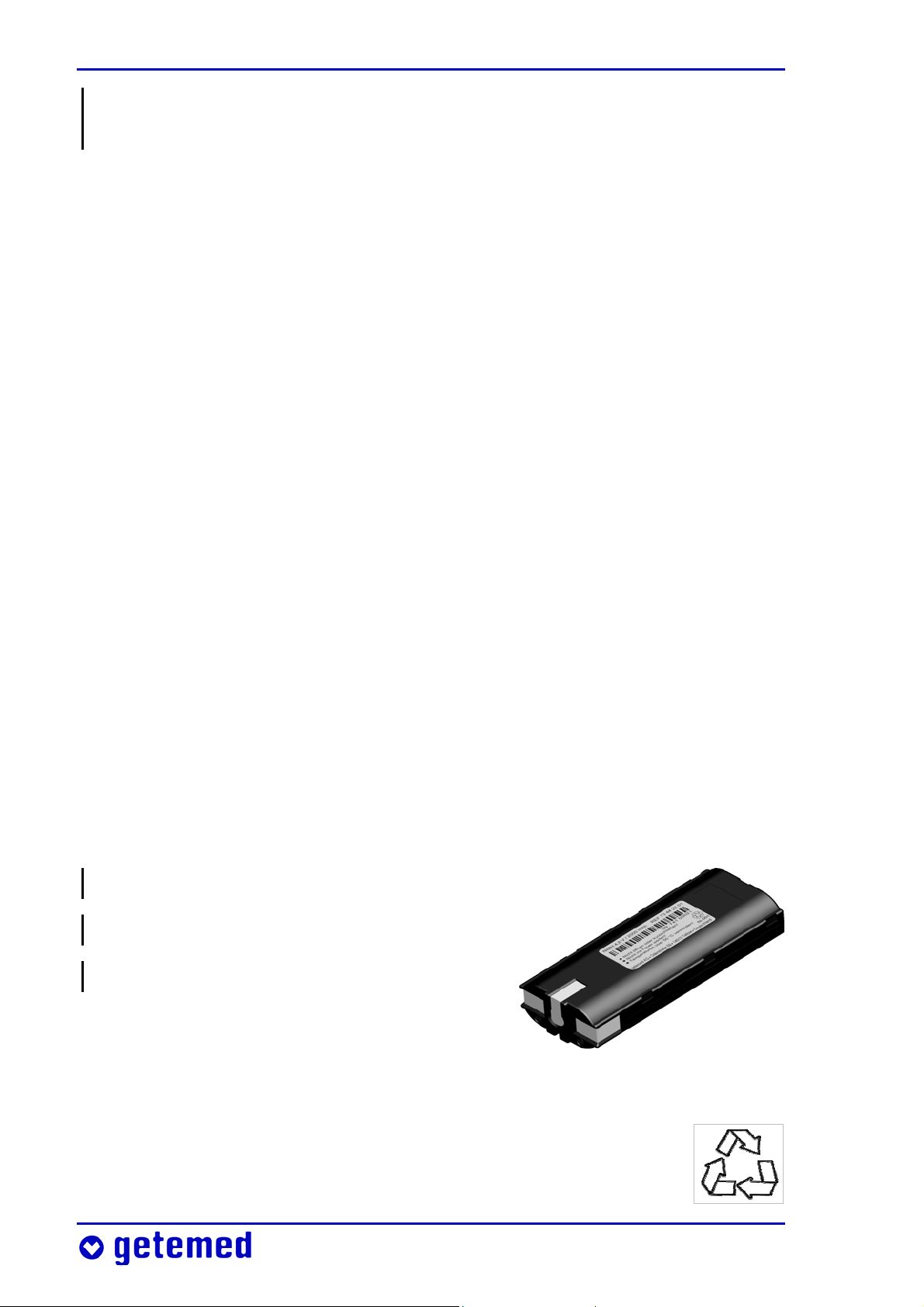
3.6.3 Using the rechargeable block battery
Note the warnings on the rechargeable block battery’s label.
Do not open or short-circuit!
Do not throw into a fire!
Avoid temperatures over 50 °C!
The charging time for the block battery is
at most six hours.
Fig. 4 Rechargeable block battery
Also note the recycling symbol on the label. This means
that the block battery must be recycled when its service life
has expired.
Page 27

Safety 27
Do not expose the block battery to direct sunlight. For example,
temperatures greater than 50 °C can easily occur on a vehicle’s
dashboard or rear shelf.
When you intend to use VitaGuard® powered from the rechargeable
battery block and disconnected from the supply network, you must
first make sure that the block battery is fully charged. For this reason, check the “Battery charging” LED. The battery is being charged
as long as this LED light is continuously on. When the
LED flashes every second, the battery is full and compensation charging is activated.
Sometimes the light will go out for a short time in the interval between battery and compensation charging.
3.7 Safety with proper maintenance only
VitaGuard® can operate safely and reliably over the long term only
when it is subject to proper maintenance and use.
Check visually for any damage on VitaGuard®, the patient cables
including the connections, the external power adapter, and the SpO2
sensor every time you use VitaGuard® for monitoring.
Every eighteen months at the latest VitaGuard® and accessories
must be serviced by getemed AG to comply with safety regulations.
Repairs must be performed by getemed
sary procedure with your authorized dealer.
For the protection of our service personnel, disinfect VitaGuard® and
the patient cables with Virkon®, available as a spray or wiping solu-
AG only. Clarify the neces-
tion, before sending them to getemed AG.
3.7.1 Cleaning VitaGuard® and accessories
Before cleaning VitaGuard®, remove the batteries.
Page 28

28 Safety
Before cleaning VitaGuard®, detach the cables from the monitor and
from the patient.
Do not under any circumstances use solvents like ether, acetone, or
benzene. These substances can cause malfunctions and attack the
housing plastic.
Also, do not use any cleaning agents containing abrasive substances
and no coarse brushes or hard objects.
VitaGuard® and accessories can be cleaned any number of times
when the recommended cleaning agents are used.
VitaGuard® and accessories must not be sterilized.
VitaGuard® and the cable plugs must not be immersed or otherwise
penetrated by liquid.
Cleaning the exterior is best done with a non-linting cloth moistened
slightly with water or a mild soap solution.
getemed AG recommends disinfecting the device with Virkon®,
available as a spray or wiping solution.
Patient cables can be cleaned with liquid Cable Care or with a 70%
alcohol solution. Baby oil has proved to be effective in removing
residue from adhesive strips.
The VitaGuard® bag can be washed by hand at 30 C. It must not be
put in the laundry dryer.
3.7.2 Checking and cleaning the battery terminals
Check the battery compartment every month for traces of leaking
and for deposits on the battery terminals indicating leaks. Contact
your authorized dealer and clarify further procedures when a battery starts to leak.
The battery compartment and how to replace the batteries are
explained in the section “Replacing batteries” on page 33.
Page 29

Safety 29
3.8 Disposing of non-rechargeable batteries, the
device, and accessories
getemed AG takes back all of the parts it delivers. For hygiene reasons
these parts do not extend to consumables like sensors that have been
in direct contact with the patient.
The symbol of the crossed-out waste container on the battery packaging is to remind you that under no circumstances must you dispose of batteries in normal household waste. As the end consumer
you are legally obliged to return used batteries or dispose of them
properly. You can return used batteries to us.
Place consumables like sensors in a plastic bag before disposing of
them in household waste.
Please do not send us any used sensors.
Page 30
30 Description
4 Description
We recommend placing VitaGuard® in the bag provided. This bag protects the monitor and can be hung from a site where it cannot fall.
Fig. 5 VitaGuard® and bag with power and patient cables
Page 31

Description 31
4.1 Power supply
VitaGuard® is usually delivered with the power adapter
for European supply networks. For other supply networks, contact getemed for the appropriate plug
adapter. Observe the information in “Power supply
reliability” on page 24.
Fig. 6 Power adapter socket
VitaGuard® is normally
supplied by the power
adapter (Fig. 7, left) in the
230 V/50 Hz supply network.
The NAK
3000-2 automo-
bile power supply adapter
(Fig. 7, right) for vehicle
dashboards can be inserted
in this socket.
Fig. 7 Power adapter for 230 V/ 50 Hz supply network and automobile power supply
When VitaGuard® is supplied by the external power adapter, the
green LED lights up next to the power adapter symbol. In addition,
the display backlight is activated when VitaGuard® is switched on.
When VitaGuard® is supplied by the power adapter only, without inserted batteries, a display message will prompt you to insert batteries.
When VitaGuard® is supplied by the power adapter, charging of the
inserted rechargeable block battery is activated. The LED next to the
battery symbol illuminates.
Page 32

32 Description
4.1.1 Power failure with inserted batteries
VitaGuard® automatically switches to battery mode when the external power supply fails or the power adapter is disconnected. In this
event a technical alarm is permanently emitted until the power
supply has been reinstated or the <Esc> key pressed.
When the supply network LED is off, but you can still see the usual
monitor displays, VitaGuard® is being supplied by the batteries.
4.1.2 Power failure without batteries
VitaGuard® is fitted with an internal battery. This provides the voltage for an acoustic signal that is emitted when monitoring cannot be
continued during a power failure.
The acoustic alarm from the internal battery does not stop until
VitaGuard® has been switched back on after the power adapter has
been reconnected or batteries have been inserted.
A power failure jeopardizes monitoring when
the batteries in the VitaGuard® are nearly depleted or
no batteries have been inserted and VitaGuard® is disconnected
from the external power adapter.
To stop the power draw on the internal battery, it is important that
non-rechargeable batteries are inserted as quickly as possible or,
better, the power adapter is reconnected.
VitaGuard® must not be used for monitoring when the internal
battery is depleted. This status appears on the display.
A new internal battery can be installed at getemed AG only, so you
must continue monitoring with a replacement device until the internal battery has been displaced.
Page 33

Description 33
4.1.3 Replacing batteries
Switch off VitaGuard® before replacing batteries.
Push back the catch and
lift off the battery cover to
open the battery compartment. Insert either
four non-rechargeable
batteries or the rechargeable block battery.
Fig. 8 Opening the battery compartment
Make sure that the + symbols on the batteries and
in the compartment match
before inserting non-rechargeable batteries.
Fig. 9 Opened battery compartment and polarity
Observe the following instructions when you use the rechargeable
block battery.
Never use force to insert the block battery.
The bottom of the block battery has a guide groove that prevents
the battery from being inserted the wrong way. Make sure when
inserting the block battery that the labeled side is on the top and
the metal terminals point to the device label.
Page 34

34 Description
You will feel a slight
pressure from the terminal spring connections when inserting
the block battery.
Fig. 10 The arrows show how the block battery is correctly inserted.
4.1.4 Using the automobile power supply adapter
Use only the NAK 3000-2 automobile power supply adapter to operate VitaGuard® from a vehicle’s dashboard.
Do not leave the automobile power supply adapter overnight in the
vehicle (particularly during the cold season). Otherwise condensation may form on and in the device.
The NAK 3000-2 automobile power supply adapter is connected to
the VitaGuard® power adapter socket. NAK 3000-2 features a universal safety plug (DIN ISO 4165) for the dashboard lighter. Automobile
power supply mode is indicated on VitaGuard® by the green LED
beside the power adapter symbol.
The specifications of the automobile power supply adapter are as follows:
Input .............................................. Automobile voltage supply at 12–24 V
Output ......................................................................................................... 9 Vdc
Max current ........................................................................................ <
500 mA
Operating temperature ............................................................. +5 to +50 °C
Connection to VitaGuard® ........................................................... 3-pin plug
Connection to automobile supply .... Universal safety plug (DIN ISO 4165)
Connecting cable length .......................................................... 2 m ± 20 cm
Page 35

Description 35
4.2 VitaGuard® connections
Fig. 11 Overview of VitaGuard® connections
For safety reasons, only those accessories that getemed AG has
delivered or approved must be connected to VitaGuard®.
Hold VitaGuard® firmly with one hand when connecting and disconnecting plugs.
Never use force when connecting and disconnecting cables. Always
insert and remove the plugs parallel to the sockets to prevent damage to the sensitive contacts.
Only the doctor, in full knowledge of the information under
“Connections to the USB and AUX ports” on page 79, must decide
which devices are connected to the USB and AUX ports.
4.2.1 Patient cable for SpO2 sensors
Fig. 12 SpO2 socket
The patient cable for the SpO2 sensors is connected to the SpO2
socket.
Page 36

36 Description
4.2.2 Power adapter
Fig. 13 Power adapter socket
The external power adapter socket is for connecting the NA 3000-2 external power adapter or the NAK
3000-2 automobile power supply adapter.
4.2.3 Sound outlet (no socket)
Fig. 14 Sound aperture
The outlet in the figure is not a socket, but a sound hole for the
internal system monitor buzzer.
This outlet emits a pulsating sound when the external power adapter is disconnected from the monitor and no batteries are inserted.
The sound outlet is located between the cable sockets so that it
cannot be covered by objects such as cushions or curtains.
Page 37

Description 37
4.2.4 USB port
Fig. 15 USB port
The USB (universal serial bus) port serves to read out stored data and
to modify the VitaGuard® settings via a PC.
4.2.5 AUX port
Fig. 16 AUX port
The AUX (auxiliary) port can take the following connections:
Two analog inputs
Modem for communicating data
Nurse call unit
External alarm unit
VitaGuard® cannot confirm whether an alarm signal has been reported by a nurse call unit. As explained in the section “Alarm test”
on page 56, check each time you switch on the device that an alarm
signal is really transferred and the alarm reported.
Page 38

38 Description
Measure the time it takes for an alarm to be reported and the time
needed to reach the patient. No more than ten seconds must pass
between these times. Observe the operating instructions for the
nurse call unit.
4.3 Membrane key panel
Do not apply excess pressure to the keys.
VitaGuard® recognizes key presses only when the keys have been
pressed for about one second.
There are six membrane keys on the top side of VitaGuard®.
Fig. 17 Keys on the top side
Page 39

Description 39
4.3.1 Direction keys
With the direction keys you navigate from one
window to the next.
The direction keys also allow you to navigate within
the menu structure.
Fig. 18 Direction keys
4.3.2 <Enter> key
The <Enter> key switches VitaGuard® on and off.
The <Enter> key also lets you confirm changes to
the monitor settings.
Fig. 19 <Enter> key
4.3.3 <Esc> key
When an alarm is triggered, the <Esc> key serves to deactivate the
acoustic alarm signal for a set alarm mute time. During an alarm
condition the red alarm LED and the violated alarm limit flash. The
acoustic alarm is again emitted if the alarm condition persists after the alarm mute time has expired. Pressing the
<Esc> key during the alarm mute time a second
time reactivates the acoustic alarm.
Fig. 20 <Esc> key
Also when an alarm has automatically ended (because the vital
functions have restabilized by themselves) the alarm LED and the
violated alarm limit continue to flash until you press the <Esc>
key. The alarm LED, however, flashes slower than during an alarm.
Page 40

40 Description
The <Esc> key cancels unsaved changes to the monitor settings or
moves back to the next-higher menu.
4.4 Color LEDs (Light Emitting Diodes)
When VitaGuard® is switched on, all LEDs light up for a short time so
that you can see they work properly. During this time, the alarm LED
first lights up red and then yellow.
4.4.1 Alarm LED
In the event of a higher-priority alarm, i.e. a
physiological alarm, the alarm LED flashes red.
In the event of a medium-priority alarm, i.e. a
technical alarm, the alarm LED flashes yellow.
4.4.2 Heart LED
The LED with the heart symbol flashes with every
pulse of the patient. In other words, this LED flashes
as fast as the heart beats.
Fig. 21 Alarm LED
Fig. 22 Heart LED
The flashing green LED shows you even in complete darkness that
monitoring is activated.
Also, the System menu lets you switch on and off an acoustic signal
that is emitted synchronously with the pulse.
Page 41

Description 41
4.4.3 Power supply and battery LEDs
When the LED with the
power adapter symbol
lights up, VitaGuard® is
being powered from the
supply network or an
Mains supply active Block battery charging
automobile power supply.
Fig. 23 Power supply LEDs
When the LED with the power adapter symbol does not light up,
but the usual monitor displays are visible, VitaGuard® is being
supplied by batteries (four non-rechargeable batteries or the rechargeable block battery).
The light from the LED with the battery symbol is permanently on
when the block battery is being charged in VitaGuard®. A depleted
block battery takes up to six hours to recharge.
When the block battery is fully charged the LED with the battery
symbol flashes every second to indicate that compensation charging
is active. The block battery must therefore be fully charged at all
times in the event that the power supply from the external power
adapter fails.
4.5 The display
Each of the “Alarms, displays, and views during monitoring” are explained on page 56. Pressing the Y key in View 1 takes you to the Info
screen with the current information for the doctor. Pressing it again
takes you to the System menu for the basic VitaGuard® settings.
After the monitor is switched on it can take up to twenty seconds
before the first values are displayed.
Page 42

42 Description
1
2 2a
2a
2b
Fig. 24 Current values and alarm limits in View 1
1 The status line at the top of the display shows messages (on the
left) and symbols (on the right) for the external power supply and
alarm activation.
2 For both vital functions, as here SpO
each vital function [2a] is shown in large digits. Smaller digits to
the right show the set alarm limits [2b].
[2], the current value for
2
Page 43

Steps before and after monitoring 43
5 Steps before and after monitoring
The following summary shows you all the necessary measures that
need to be taken before monitoring. Also read information on how
VitaGuard® is switched on and off.
The doctor and the qualified medical staff are responsible for all
other important activities when “Preparing for a new patient” (see
page 78).
5.1 Summary of steps before monitoring
Insert the battery or batteries (do not switch on yet!).
Use the external power adapter to connect VitaGuard® to the
supply network (do not switch on yet!).
Attach the SpO
Connect the SpO
Connect the SpO
sensor to the patient.
2
patient cable to VitaGuard®.
2
sensor to the patient cable.
2
Switch on VitaGuard® as explained in the next section.
Make sure that after the monitor is switched on the indicator
lamps light up briefly and a short sound is emitted by the alarm
buzzers.
Check that the alarm limits displayed are the same as those
recommended by the doctor.
5.2 Switching on
Press the <Enter> key for several seconds to switch on VitaGuard®.
In the first minute of operation no acoustic signals are emitted so
that you have time to check all cables. The alarm bell is crossed out
Page 44

44 Steps before and after monitoring
for this time and the remaining time is shown next to it. Text messages, on the other hand, are shown from the beginning.
When no patient cable is connected, an acoustic reminder signal is
emitted as a short tone every twenty seconds after the monitor is
switched on. The technical alarm for cable monitoring is not activated
until the patient cable is connected and the first plausible data have
been calculated. A text message in the status line reports from the
beginning that the cables are being checked.
After the device has been switched on, the following displays and
signals show you that the monitoring system is fully operable.
All indicator LEDs light up briefly. During this time the alarm LED
first lights up red and then yellow.
A brief tone is emitted to indicate that the acoustic alarm buzzer
is fully operable.
If the alarm buzzer does not emit the acoustic signal after the device
has been switched on, you must immediately send VitaGuard® to
getemed AG or your authorized dealer for inspection. Please consult
your authorized dealer for a replacement device.
Observe the patient carefully until the replacement device arrives.
Bear in mind that the patient is not being monitored at this time
and that no alarm will be reported in an emergency.
5.3 Switching off
Always switch off VitaGuard® in the manner described here.
1 Press the <Enter> key and keep this pressed: the message Press
Esc key appears.
2 Briefly press the <Esc> key, still keeping the <Enter> key pressed,
and then release both keys.
The switch off command is acknowledged by two short beeps.
Page 45

Steps before and after monitoring 45
Data must be stored before the device finally switches off. For this
reason, VitaGuard® needs about another two seconds after the keys
are released until it switches off completely.
5.4 Summary of steps after monitoring
Switch off VitaGuard® as explained in the previous section.
Detach the SpO
from the skin.
If the procedure concerning stored data has not been clarified during your training, then please contact your doctor.
sensor, carefully removing the adhesive strip
2
Page 46

46 Preparing for SpO2 monitoring
6 Preparing for SpO2 monitoring
The information in this section refers primarily to the use of adhesive strip sensors. Also available, however, are SpO2 sensors that can
be disinfected and reused (permanent sensors) for brief examinations and for monitoring patients with allergies.
LNOP® Neo will be explained as an example SpO
children.
LNOP® Adt will be explained as an example SpO
adults.
Preparing for SpO
monitoring involves:
2
sensor for
2
sensor for
2
attaching the sensors to the patient
laying and securing the patient cable
connecting the SpO
patient cable to VitaGuard®
2
6.1 Safety instructions for SpO2 monitoring
For hygiene reasons, check that there is no damage to the sensor’s
packaging before opening it. Use adhesive strip sensors on the one
patient only.
Remove the adhesive sensors no later than every eight hours and
permanent sensors no later than every four hours so that you can
inspect and, if necessary, clean the attachment sites on the patient’s
skin.
When the blood flow or attachment site is not satisfactory, attach
the sensor to a different site, and inspect this site more often.
Be particularly careful with patients exhibiting weak blood flow:
failing to check the sensors frequently may lead to skin damage and
pressure-induced necrosis. Check no later than every two hours in
these cases.
Page 47

Preparing for SpO2 monitoring 47
Connect the SpO2 sensors only to the corresponding patient cable
and this only to the corresponding socket on VitaGuard®.
Do not use adhesive strip SpO
sensors on patients exhibiting aller-
2
gic reactions to adhesive strips or similar.
Securing sensors incorrectly, e.g. too tightly, can damage tissue.
Do not use damaged sensors. Replace sensors immediately if they
exhibit any damage.
Do not immerse the sensors in liquids and do not attempt to sterilize
them.
An improperly attached sensor can falsify measurements.
Do not attach the SpO
sensor to a limb that has or will have a
2
catheter or pressure cuff during monitoring.
Secure the sensors and cables so that they cannot harm, strangle, or
be swallowed by the patient. Always lay the patient cable at a safe
distance from the patient’s head and neck. Lay the patient cable
when monitoring small children inside their clothing so that it exits
at the foot. On larger children and adults you can, for example, lay
the patient cable so that it exits between the trousers and pullover.
To prevent damage, avoid all kinks, folds, and any other unnecessary
bends in the sensor cable.
6.2 Operation of SpO2 sensors
SpO2 sensors consist of a transmitter diode (referred to as “transmitter” in the following) and a receiver. The transmitter is identified by
the red star symbol on the adhesive strip. The receiver is identified by
its round window and the white plastic part on the adhesive strip
behind it.
The transmitter emits light, the receiver detects this light. When this
light penetrates arterial blood vessels, the composition and intensity
of the light picked up by the receiver change.
Page 48

48 Preparing for SpO2 monitoring
The SpO2 monitor can calculate the percentage level of blood oxygenation from the composition of the light picked up by the receiver.
However, it is important that no other light, whether daylight or
ambient light, can reach the receiver. More detailed explanations can
be found in the section “Measuring principle for the SpO
on page 103.
monitor”
2
6.3 SpO2 sensor adapted to the patient’s size and
weight
The following lists a number of SpO2 sensors that are also available.
The LNOP® Neo delivered with VitaGuard® is an adhesive strip
sensor for measuring the functional arterial blood oxygen saturation (SpO
Sensors of the type LNOP® NeoPt are available for monitoring
premature infants with sensitive skin.
The sensor LNOP® Pdt can be used on children weighing between
) of infants weighing up to 10 kg.
2
10 and 50 kg.
The sensor LNOP® Adt is suitable for patients over 30 kg.
Information on other sensors can be obtained from getemed AG or
your authorized dealer.
6.4 Choosing the sensor site
Always choose a site that is intact, has good blood flow, and
covers completely the receiver window. Information on choosing
the right attachment site can be found on the sensor’s packaging.
Choose a site such that the sensor’s transmitter and receiver can
lie exactly opposite each other.
The distance between the transmitter and the receiver should not
be greater than two centimeters.
Page 49

Preparing for SpO2 monitoring 49
On infants with thick or swollen feet, the big toe is often better
than the whole foot.
Clean and dry the attachment site.
Choose a site where the sensor and patient cable can least restrict
the patient’s freedom of movement.
6.5 Repositioning or replacing the sensor
Sensors used for a long time do not adhere as well as new ones.
When VitaGuard® does not display plausible values for the pulse rate
and oxygen saturation, the sensor may not be attached to the optimal site or may not be properly secured.
Check the sensor’s position, and if necessary, move the sensor to a
different site.
Always replace a sensor when the displayed pulse rate and the
displayed percentage level of oxygen saturation remain unconvincing despite the sensor’s new site.
6.6 Reasons for unconvincing SpO2 values
Clarify with the doctor whether one of the following situations may
have arisen:
the sensor is improperly secured or used (e.g. when the transmit-
ter and receiver do not lie exactly opposite each other),
the patient moves vigorously,
the sensor picks up bright ambient light, e.g. from powerful
lamps, IR heater lamps, direct sunlight, etc.,
venous pulsation,
a catheter or pressure cuff has been applied to the same limb as
the sensor,
Page 50

50 Preparing for SpO2 monitoring
the blood exhibits appreciable quantities of dysfunctional hemo-
globin, e.g. carboxyhemoglobin or methemoglobin,
blood dyes have been used such as indocyanine green, methylene
blue, or other substances that contain coloring agents and therefore affect the blood color.
6.7 Why the pulse rate is not displayed
Clarify with the doctor whether one of the following situations may
have arisen:
The sensor is secured too tightly (dangerous for the patient),
Bright ambient light,
Inflated blood pressure cuff on the same limb as the sensor,
Arterial occlusion near the sensor,
Low blood pressure, serious vasoconstriction, anemia, hypother-
mia, cardiac arrest, or shock.
6.8 Attaching the SpO2 sensor to an infant’s foot
Note that the SpO
here as an example. The doctor must decide which SpO2 sensor type
to use in each case.
LNOP® Neo is an SpO2 sensor for
use with one patient only weighing
sensor type LNOP® Neo for infants is described
2
less than 10 kg.
Fig. 25 Label on the LNOP® Neo SpO2 sensor
LNOP® Neo is free of latex, is not sterile, and cannot be sterilized.
The foot is the preferred attachment site on newborns. Alternative
sites are also the palms and backs of the hands.
Page 51

Preparing for SpO2 monitoring 51
On infants weighing between 3 and 10 kg with thick or swollen feet,
the LNOP® Neo sensor can be secured to the big toe. In this case, the
following information for the sensor’s receiver does not refer to the
sole of the foot, but to the underside of the big toe. An alternative
attachment site is also the thumb.
1 Open the packaging and remove the sensor. Hold the sensor at
the stem of the Y and remove the protective cover from both the
sensor and the adhesive strip. Align the
end of the sensor so that the contacts
point away from the patient. Align the
receiver along the fourth toe and press it
against the sole of the foot (Fig. 26).
2 Align the transmitter window along the
top of the foot directly opposite the
receiver. Wrap the adhesive strip around
the foot to secure the transmitter and
receiver (Fig. 27). Check and if necessary
correct the positions.
Fig. 27 Aligning the sensor and receiver
3 The opening in the receiver window
must be completely covered by the foot
(Fig. 28).
Fig. 28 Correctly attached LNOP® Neo sensor
Fig. 26 Positioning the sensor
6.9 Attaching the SpO2 sensor to an adult’s finger
Note that the SpO
here as an example. The doctor must decide which SpO2 sensor type
to use in each case.
sensor type LNOP® Adt for adults is described
2
Page 52

52 Preparing for SpO2 monitoring
The LNOP® Adt sensor designed for
adults weighing over 30 kg is
identified by the label illustrated
on the right.
Fig. 29 Label on the LNOP® Adt SpO2 sensor
The preferred attachment sites on adults are the ring and middle
fingers of the non-dominant hand. Alternative attachment sites are
the other fingers of the non-dominant hand. On immobilized patients
or patients whose hands cannot be used as attachment sites, the big
or middle toe can be used.
1 Open the packaging and remove the
sensor. Hold the sensor with the printed
beige side downwards and bend it back
to draw off the rear side. Align the sensor so that the receiver can be attached
first (Fig. 30).
2 Now press the receiver on the fingertip
and wrap the adhesive T ends around
the finger (Fig. 31).
Fig. 31 Positioning the receiver on the fingertip
3 Next wrap the sensor with the transmit-
ter and the finger design around the fin-
Fig. 30 Positioning the sensor
gernail, and wrap the flaps downwards,
one after the other, around the finger
(Fig. 32).
Fig. 32 Aligning the sensor and receiver
Page 53

Preparing for SpO2 monitoring 53
4 When the transmitter and receiver are correctly attached, they
should be exactly opposite each other
(Fig. 33). Check and if necessary correct
the sensor’s position. The receiver
window must be completely covered by
the tissue.
Fig. 33 Correctly attached LNOP® Adt sensor
6.10 Connecting the SpO2 sensor and patient cable
Hold the sensor’s contact blade so that the metal contacts are on the
top and the two Masimo symbols on the blade and patient cable are
opposite each other. Insert the contact blade into the patient cable
until it engages (Fig. 34). Pull carefully on
the contact blade to check that it has
engaged properly. You can now secure the
patient cable to the patient with an adhesive strip.
Fig. 34 Connecting the patient cable and sensor contact
6.11 Connecting the SpO2 patient cable to
VitaGuard®
Insert the patient cable’s monitor plug into the SpO2
socket on VitaGuard®. The Masimo inscription on the
monitor plug must be on top. You should feel the
monitor plug engage.
Fig. 35 SpO2 socket
Page 54

54 Preparing for SpO2 monitoring
6.12 Disconnecting the SpO2 sensor from the
patient cable
Use the thumb and index finger of one
hand to carefully press the two buttons on
the side of the patient cable’s socket (Fig.
36). Carefully pull the end of the sensor to
withdraw it.
Fig. 36 Disconnecting the sensor from the patient cable
6.13 Disconnecting the SpO2 patient cable from
VitaGuard®
Using your thumb and index finger, carefully press
the two levers in the patient cable’s monitor plug,
and carefully pull out the plug.
Fig. 37 Two levers for securing and releasing the patient cable plug
6.14 Reusing and refastening SpO2 sensors
When the SpO2 sensors are treated with care they can be used several
times on the same patient as long as the adhesive surfaces still
adhere and the transmitter and receiver windows are cleaned at
regular intervals.
Disconnect the sensor from the patient cable before you reattach or
refresh it.
There are replacement adhesive strips available for the LNOP®
Neo sensor used on infants.
Page 55

Preparing for SpO2 monitoring 55
When sensors have been in use for a short time only, you can
refresh the adhesive surfaces with a cotton swab saturated with a
70% isopropanol solution. Leave the sensor to dry thoroughly in
air before reattaching it.
A sensor can be secured with an adhesive strip on less sensitive
patients. Velcro strips are available for more sensitive patients.
Use a new sensor when the old one can no longer be properly secured.
Page 56

56 Alarms, displays, and views during monitoring
7 Alarms, displays, and views during
monitoring
Immediately call the emergency services when a patient remains
unconscious after being shaken or addressed.
7.1 Alarm test
CAUTION: When beginning monitoring at a new site, make sure that
you can clearly hear the alarm signal and quickly reach the patient.
For this purpose, deliberately trigger a technical alarm.
When a patient is connected you can deliberately trigger an alarm by
disconnecting the SpO
sensor from the SpO2 patient cable.
2
7.2 Pulse rate values based on age groups
Bear in mind that the Pulse rate drops considerably with increasing
age. The doctor must check and, if necessary, adapt the alarm limits
for each patient’s age group.
The percentage level of arterial blood oxygenation displayed as
%SpO
patient’s age group.
The average pulse rate of an infant is much higher than that of an
adult. Accordingly, the alarm limit e.g. for bradycardia (too low a pulse
rate) must be set considerably higher for an infant than for an adult
normally ranges between 97 and 99%, irrespectively of the
2
patient. As an orientation aid, the following table lists some medically
acknowledged approximate pulse rates for various age groups and
stress situations.
Page 57

Alarms, displays, and views during monitoring 57
Pulse rate / min Age group
Sleep Rest Stress (e.g. fever)
Newborns 80–160 100–180 max 220
1 week to 3 months 80–200 100–220 max 220
3 months to 2 years 70–120 80–150 max 200
2 to 10 years 60–90 70–110 max 200
10 years and older 50–90 55–90 max 200
7.3 Alarm message priorities in the status line
Fig. 38 Status line on the VitaGuard® display
Physiological alarms have high priority. The text messages of
physiological alarms end with three exclamation marks.
Technical alarms have medium priority. The text messages of
technical alarms end with two exclamation marks.
!!!
!!
7.4 Physiological and technical alarms
VitaGuard® generates two types of alarms: physiological and technical alarms.
A physiological alarm is generated when VitaGuard® detects
values that violate one or more of the set alarm limits for longer
than the set period.
There are simple alarm limits, e.g. the Lower limit for the Pulse rate,
and there are alarm limits based on the interaction of several monitor
settings, e.g. the deviation alarms.
A technical alarm is generated when monitoring is no longer
reliable for technical defects. When a technical alarm condition
occurs, a life-threatening situation may escape detection.
Page 58

58 Alarms, displays, and views during monitoring
When, for example, a technical alarm condition has occurred, yet at
the same time a physiological alarm condition has been detected, the
physiological alarm condition has priority and the physiological alarm
is reported.
NOTE An alarm mute time of ten seconds follows a technical alarm
triggered by problems with the SpO2 sensor. This delay is to prevent
false alarms when the physiological parameters are being recalculated. During the alarm mute time, the bell symbol in the status line
is crossed out.
7.5 Differentiating physiological and technical
alarm signals
The Alarm tone pitch can be set in the System menu so that alarms
are heard over the prevailing background noise.
The urgency or priority of an acoustic alarm can be recognized by its
characteristics described in the following.
High-priority messages emit two sequences of five tones that are
repeated every ten seconds.
The interval between each tone packet is two seconds. Also, there is a
slightly longer interval
between the third and
fourth tone of each
sequence.
Fig. 39 Characteristics of the high-priority acoustic alarm signal
Medium-priority messages emit a sequence of three tones which is
repeated every 5.2 seconds.
7.6 Acoustic information signals
If wished, the alarm unit next to the display can produce a short
acoustic signal to accompany each pulse.
Page 59

Alarms, displays, and views during monitoring 59
7.6.1 Information signals from the alarm unit next to
the display
After the monitor is switched on, an acoustic reminder signal is
emitted every twenty seconds until plausible data have been detected.
7.6.2 Information signals from the sound aperture
between the sockets
A pulsating tone is emitted if the external power adapter is disconnected and no batteries are installed.
7.7 The visual alarm signals
A high-priority alarm, i. e. physiological alarm, causes
the alarm LED to flash red.
A medium-priority alarm, i. e. technical alarm, causes
the alarm LED to flash yellow.
7.8 Status line displays
During monitoring the status line is displayed in all views.
Fig. 40 The status line displayed in all views
The monitor’s text messages appearing on the left are explained in
detail in the section “Alarm messages – meanings and other information” on page 62. On the right of the status line are three symbols.
Power supply
Page 60

60 Alarms, displays, and views during monitoring
The power supply symbol indicates whether the NA3000-2 external
power adapter or the automobile power supply adapter is
connected. When a power adapter is connected, the symbol
appears as illustrated on the right. Otherwise the symbol is
crossed out.
Battery voltage indicator
The battery voltage indicator depicts the voltage from the
batteries. When the block battery is being recharged this
symbol is animated, i. e. a filling animation is displayed.
Alarm indicator
When you interrupt an acoustic alarm by pressing the
<Esc> key, the bell symbol is crossed out. To the left of
the bell, the remaining alarm mute time is displayed in seconds. This
mute time applies only to the current alarm type.
When a new alarm condition is detected, the acoustic alarm is emitted before the alarm mute time has expired.
Pressing the <Esc> key a second time immediately ends the Alarm
mute time.
The alarm bell outline indicates that all acoustic alarm signals
are enabled.
In the event of an alarm, the alarm bell is filled out and flashes.
7.9 SpO2 monitor alarms
After the monitor has been switched on, it can take up to twenty
seconds before the first values are displayed.
7.9.1 Physiological SpO2 alarms
The currently set alarm limits are always displayed. When the displayed SpO
value falls below the SpO2 Lower limit for longer than
2
Page 61

Alarms, displays, and views during monitoring 61
the period set under Hypoxia alarm delay or exceeds the SpO2 Upper
limit for longer than the period set under Hyperoxia alarm delay, an
acoustic alarm signal is emitted and the corresponding message is
displayed. The affected alarm limit and the alarm LED flash.
Go immediately to the patient when an alarm occurs and check the
patient’s condition.
When the SpO
value returns within the permitted range the alarm is
2
ended automatically. In this case, the affected alarm limit and the
alarm LED continue to flash until the <Esc> key is pressed to indicate
that an alarm has occurred.
The SpO
Upper limit is deactivated when it is set to 100% (factory
2
setting). We recommend setting an upper limit when the patient is
undergoing oxygen therapy.
7.9.2 Technical SpO2 alarms
The section “Table of technical alarm messages” on page 64 can be
consulted for the technical alarm signals and the recommended
troubleshooting procedures.
The SpO
messages. Until the problem has been eliminated, the SpO
monitor displays technical alarms with the corresponding
2
value and
2
the pulse rate are replaced by a question mark symbol. Perfusion and
signal IQ are set to zero.
7.10 Pulse rate alarms
After the monitor is switched on, it may take up to twenty seconds
before the first values are displayed.
The currently set alarm limits are always displayed.
When the displayed Pulse rate [PR]
Page 62

62 Alarms, displays, and views during monitoring
falls below the Lower limit for longer than the set Bradycardia
delay or
exceeds the Upper limit for longer than the set Tachycardia
delay
VitaGuard® emits an acoustic alarm signal and displays the corresponding message. The violated alarm limit and the alarm LED flash.
Go immediately to the patient when an alarm is reported and check
the patient’s condition.
The alarm is ended automatically when the pulse rate returns within
the permitted limits.
Deviation alarms can also be activated in addition to the alarms
based on permanently set limits.
7.11 Alarm messages – meanings and other
information
The tables in this section list in alphabetical order all the text messages that can appear on the VitaGuard® display together with more
detailed explanations and troubleshooting hints.
7.11.1 Order of equal-priority alarm conditions
The numbers in the No. column on the right indicate the internal
priorities that VitaGuard® uses to process the respective messages.
This is of importance to the doctor only.
7.11.2 Table of physiological alarm messages
Physiological alarms are reported with high priority.
Page 63

Alarms, displays, and views during monitoring 63
Message Meaning Information No.
Pulse rate
and SpO2!!!
Pulse rate
too high!!!
Pulse rate
too low!!!
Pulse rate
drop
A pulse rate alarm and an
SpO2 alarm have occurred
simultaneously.
The calculated pulse rate
exceeds the set Upper
limit for longer than the
set Tachycardia delay.
The calculated pulse rate
has fallen below the set
Lower limit for longer
than the set Bradycardia
delay.
The current pulse rate
has fallen below the
See the messages and information for
“Pulse rate too high/ too low” and “SpO2
too low”.
When there is no tachycardia:
- Strong artifacts caused by excessive
movement trigger false alarms.
- The monitor, cable, or sensor is defect.
- The set Upper limit is too low.
When there is no bradycardia:
- No pulse is detected.
- There are abnormal beats.
- The monitor, cable, or sensor is defect.
- The set Lower limit is too high.
When there is no pulse rate drop:
- The pulse rate and/ or the average
2
7
6
11
detected!!!
(when
activated)
Pulse rate
rise
detected!!!
(when
activated)
SpO2 too
high!!!
value based on the set
Averaging interval by
more than the percentage deviation value set
under Trend deviation (–).
A pulse rate rise is
detected in the same
manner as a pulse rate
drop, but Trend devia-
tion (+) is used instead.
The calculated SpO2
exceeds the set Upper
limit for longer than the
set Hyperoxia alarm
delay.
pulse rate is incorrectly calculated for
the reasons given under “Pulse rate
too low”.
When there is no pulse rate rise:
- The pulse rate and/or the average
pulse rate is incorrectly calculated for
the reasons given under “Pulse rate
too high”.
When SpO2 is not too high:
- The sensor is incorrectly attached, e.g.
it is too loose or too tight, the transmitter and receiver are too far apart, or
they are not exactly opposite each other.
12
9
- The sensor has become detached
- The blood flow is weak or obstructed
e.g. by a pressure cuff.
Page 64

64 Alarms, displays, and views during monitoring
Message Meaning Information No.
- Strong artifacts caused by movements
corrupt the signal.
- The monitor, cable, or sensor is defect.
- The set Upper limit is too low.
SpO2 too
low!!!
SpO2 drop
detected!!!
(when
activated)
The calculated SpO
fallen below the set
Lower limit for longer
than the set Hypoxia
alarm delay.
The currently measured
SpO2 has fallen below the
value based on the set
Averaging interval by
more than the percentage deviation value set
under Trend deviation (–).
has
2
See “SpO2 too high!!!”. 8
When there is no SpO2 drop:
- The present SpO
the set averaging interval is incorrect
for the reasons given under “SpO2 too
high”.
or the value based on
2
7.11.3 Table of technical alarm messages
13
Message Meaning Cause or elimination No.
Check
power
adapter!!
Conflicting
SpO
2
limits!!
Hardware
fault!!
Internal
data error!!
The measured voltage
from the power adapter
is less than 8 V or greater
than 10 V.
The SpO
been set higher than the
Upper limit.
The monitor has detected
an internal fault.
The internal software
monitor has detected a
data transfer error.
Lower limit has
2
- Check that the stipulated power
adapter is being used.
- Check and, if necessary, replace the
3000-2 power adapter.
NA
- Correct the SpO
limits. 20
2
- Switch off the monitor, wait for thirty
seconds, and switch it back on: if this
message persists, the monitor is defect.
- Switch off the monitor, wait for thirty
seconds, and switch it back on: if this
message persists, the monitor is defect.
16
14
18
Page 65

Alarms, displays, and views during monitoring 65
Message Meaning Cause or elimination No.
No cables
connected!!
No power
adapter !!
Recharge
battery!!
Replace
batteries!!
SpO2: Check
cable!!
The monitor discovers
that both patient cables
are not connected.
The power adapter has
been disconnected.
The battery voltage is too
low: the monitor can no
longer operate reliably
The battery voltage is too
low: the monitor can no
longer operate reliably.
The SpO2 module reports
that the SpO2 cable is not
connected.
- Connect the patient cable. 21
- Reconnect the external power adapter
or press the <Esc> key.
- Operate the monitor with the external
power adapter to recharge the block
battery, or insert non-rechargeable
batteries.
- Insert new batteries or a new block
battery or operate the monitor with
the external power adapter.
- Connect the SpO
- Replace the SpO
persists.
cable.
2
cable, if this message
2
17
32
33
26
SpO2:
Defective
sensor!!
SpO2:
Hardware
fault!!
SpO2:
Interference!!
SpO2: Pulse
search!!
SpO2:
Sensor off!!
The SpO2 module reports
that the SpO2 sensor is
defect.
The SpO2 module is not
supplying data.
The SpO2 module detects
electromagnetic interference.
When switched on, at
first, the SpO2 module
reports that it is searching for the pulse.
The SpO2 sensor is defect
or not connected.
- Replace the SpO
sensor. 27
2
- Switch off the monitor, wait for thirty
seconds, and switch it back on: if this
message persists, the monitor is defect.
- Locate any interference sources in the
direct vicinity and, if necessary, remove
them.
- When this message is displayed during
monitoring, check whether the sensors
are secured and positioned properly.
- Check whether the SpO
correctly connected to the cable; if
sensor is
2
15
30
34
28
necessary replace the sensor.
SpO2: Too
much
light!!
The SpO2 module reports
that there is too much
light.
- Protect the SpO
sources, e.g. by covering it.
sensor from light
2
31
Page 66

66 Alarms, displays, and views during monitoring
Message Meaning Cause or elimination No.
SpO2:
Unrecognized
sensor!!
The SpO2 module reports
that an unrecognized
sensor is connected.
- Replace the SpO
(use only the sensors from Masimo Inc.).
sensor
2
29
7.12 Table of information messages
Message Cause Meaning No.
Calculating
pulse rate
Internal battery
too low
The current pulse rate
cannot be displayed
while it is being
calculated.
The internal battery for
alarms during a power
The current pulse rate is displayed
after it has been calculated.
- The monitor is defect i. e. the
internal battery needs to be replaced
37
39
SpO2: Low
perfusion
SpO2: Low signal
IQ
failure is depleted.
The SpO2 module
reports that the blood
flow is too weak.
The SpO2 module
reports that the signal
quality is low.
by a technician.
- Either use a different attachment
site, or set Sensitivity to maximum
in the SpO2 menu.
- Use a different attachment site, or
check for the presence of light or
electromagnetic interference
sources in the vicinity.
35
36
- Whenever possible, prevent vigorous
movements by the patient.
Status: ok No messages 40
Page 67

Alarm and monitor settings 67
8 Alarm and monitor settings
The functions described in this section can be accessed only when
the doctor has set Settings protection to Limited in the System
menu. This setting requires a code.
The function Admit new patient in the System menu overwrites all
earlier settings.
The set alarm limits and other monitor parameters are stored and
retained when the monitor is switched back on after a battery
change.
8.1 Safety instructions for the alarm settings
It is important that the doctor responsible sets new alarm limits and
monitor parameters for each patient and for each new medical
situation. Never change alarm limits without consulting the treating
doctor.
Never set the alarm limits to extreme values that render the monitoring system useless.
When you have been given a code for changing alarm limits, it is
important that you treat this code as confidential. Life is in danger
when alarm limits are not adapted specifically to each and every
patient.
Page 68

68 Alarm and monitor settings
8.2 Summary of views and menus
The views presented here are intended to provide extensive information on the monitoring situation. When Settings protection is set to
Limited, they can be accessed with the direction keys Y and Z.
The keys U and V let you access more detailed information and enter
menus for changing monitor settings.
The U or V key takes you from the System view to the System
menu. The first setting is highlighted.
The U or V key leafs through pages on the Info display.
The U or V key takes you from View 1 or 2 to the menu “Manual
data storage or Transmit data”. This is explained in the corre-
sponding section on page 93.
The SpO
ing the respective settings and can be accessed with the U or V
key. The first setting is highlighted.
, and Pulse rate displays each feature a menu for adjust-
2
The U or V key takes you from the Events or Trends views to
detailed views, Waveforms, and Trends.
8.3 Additional views
When the doctor has configured VitaGuard® so that also the caregivers can change settings, i.e. Settings protection is set to Limited,
Views 2 is also activated in addition to View 1. View 1 is explained in
the section “The display” on page 41.
Page 69

Alarm and monitor settings 69
8.3.1 View 2 – Large data presentation and waveforms
View 2 displays in large digits the
current values for the monitored
vital functions and, on the right
in smaller digits, the set alarm
limits.
Also, each section on the left
presents a waveform of the
monitored vital function.
Fig. 41 View 2
8.4 Changing the settings
Use the direction keys to highlight a menu option or an entry in this
option. Once you have highlighted the option you want, press the
<Enter> key to change it. When you do not want to keep your
changes, press the <Esc> key.
The U key takes you to the menus.
The first entry in the list is highlighted. Use the V key to highlight the setting LCD brightness
(“Changing multiple-component
settings” is explained on page 86
for the doctor and qualified
medical staff).
Fig. 42 Menu system, “LCD brightness: 80%” highlighted
Page 70

70 Alarm and monitor settings
Press the <Enter> key. A window
appears where you can change
the old value.
Use the U and V keys to change
the highlighted value.
Fig. 43 System, “LCD brightness” highlighted in the change window
Pressing the <Enter> key after
changing a value causes a
prompt to appear with Accept:
No highlighted. Press the Y key
to highlight Accept: Yes.
Fig. 44 System, accept change to LCD brightness highlighted
Confirming the prompt Accept: Yes with the <Enter> key displays the
changed value in the list. To exit the menu press the <Esc> key.
8.5 System menu – general settings
NOTE You can familiarize yourself with the menus without
changing values. Simply press
the <Esc> key to exit each menu
and submenu without saving
changes.
Fig. 45 System menu – general settings
Page 71

Alarm and monitor settings 71
8.5.1 System\ Screen saver (Off/ On)
When Screen saver is set to On, an animation appears on the display
when no key has been pressed for five minutes.
When you press a key or an alarm is triggered, the previous mask is
displayed again.
8.5.2 System\ LCD brightness
You can set the LCD brightness from 0% to 100% in steps of 5%.
When 0%, the display’s backlight illumination is switched off. The
factory setting is 95%.
8.5.3 System\ LCD contrast
You can set the display’s contrast from 0% to 100% in steps of 5%.
The factory setting is 70%.
8.5.4 System\ Signal beep tone
You can configure the monitor to emit a brief signal tone with every
detected Pulse.
When this tone disturbs the patient
or caregivers, choose the setting Off.
The factory setting is Off.
Fig. 46 System\ submenu “Signal beep tone”
Page 72

72 Alarm and monitor settings
8.5.5 System\ Alarm tone pitch
You can set the pitch of the acoustic alarm signals to Low, Medium,
or High so that they can be heard over the expected background
noise. The DIN settings (DIN) match the alarm tone characteristics as
described from page 58 on in the section “Differentiating physiological and technical alarm signals”. As
an alternative, you can set the alarm
tone characteristic (gtm) as familiar
from other getemed devices. The
factory setting is Medium.
Fig. 47 System\ submenu “Alarm tone pitch”
8.5.6 System\ RS232 format
This submenu lets you assign the
format for online data output from
the AUX serial port.
Fig. 48 System\ RS232 format
8.5.7 System\ Settings protection On, Limited, Off
The codes that protect the alarm defaults from unauthorized
changes must be given by the doctor to those persons only whom
the doctor judges to be adequately informed about monitoring and
their responsibility for the patient. The doctor should point out that
the code must be treated as confidential, that settings should be
changed at the doctor’s request only, and that all changes must be
confirmed by the doctor.
VitaGuard® provides the following three settings for Settings protection.
Page 73

Alarm and monitor settings 73
Settings protection ON deactivates all options to change moni-
tor settings. The display presents only View 1, the Info display,
and the System menu.
Settings protection Limited enables access to all views and
menus. Of all the monitor settings, however, only the alarm limits
can be changed.
Settings protection Off enables all views and menus and allows
changes to all monitor settings.
The factory setting is Settings protection Limited.
After highlighting the function Settings protection, press the <En-
ter> key to open a submenu.
This submenu always displays Settings protection as “00” irre-
spectively of the current setting. Pressing the <Enter> key activates Settings protection.
When you enter a code Settings protection appears as Limited.
When you enter a different code, Settings protection appears as
Off.
When the wrong code has been entered three times Settings protection cannot be so easily deactivated. In this case, consult your
authorized dealer.
8.6 SpO2 display and menu
The Z key takes you from View 1 or 2 to the SpO2 display. Here you
can open the menu with the U or V key. Having highlighted a row,
press the <Enter> key to change its contents.
Page 74

74 Alarm and monitor settings
8.6.1 SpO2 view
The top half of the display presents:
1 the status line
2 the current value with the
set alarm limits
1
2
3
3 the current three-minute
trend views that update
the last value every two
seconds
Fig. 49 SpO2 view, plethysmogram, perfusion index, and signal IQ
The SpO2 trend displays the SpO2 values between 70 and 100% over
the last three minutes.
The first row under the trend view is the Signal IQ as vertical bars, the
second the Plethysmogramme. At the bottom perfusion index [PI]
and pulse rate [PR] are displayed.
When the monitor is switched on, it can take up to twenty seconds
before the first values are displayed.
Bear in mind that the plethysmogram is NOT proportional to the
pulse volume. A regular plethysmogram, for example, indicates that
the SpO2 sensor is correctly secured.
Every time the SpO2 monitor detects a pulse beat a vertical bar
appears in the Signal IQ row. The higher this bar, the better the
signal from the SpO
sensor. A high Signal IQ indicates that:
2
the sensor is correctly attached,
an adequately strong signal is detected for the arterial blood flow,
the patient does not move or is not moved too vigorously.
The calculated percentage value for Perfusion (PI) can vary between
0 and 20%. When this value is very low, SpO
and the pulse rate are
2
Page 75

Alarm and monitor settings 75
no longer monitored. When the Sensitivity in the SpO2 menu is set to
Maximum, the cut-off limit is 0.02%; when set to Standard, this limit
ranges from 0.5 to 0.02%, depending on the signal quality.
The principal of operation for this calculation can be found in the
section “Measuring principle for the SpO
monitor” on page 103.
2
8.6.2 SpO2 menu – alarm settings (Settings protection
Limited)
The SpO2 menu lets you view and
change the current SpO
settings.
Changes are permitted only
when Settings protection is set
to Limited in the System menu.
Factory settings are shown in
bold type.
alarm
2
Fig. 50 SpO2 menu for viewing and setting alarm limits
Lower limit ............................ 50, 51 ... 88 ... 99, 100 %
Lower alarm limit for the measured arterial oxygen saturation; an alarm is reported when the measured value falls
below this limit for longer than the set
Hypoxia alarm delay
Upper limit ............................. 50, 51 ... 88 ... 99, 100 %
Upper alarm limit for the measured arterial oxygen saturation; an alarm is reported when the measured value exceeds this limit for longer than the set
Hyperoxia alarm delay
Page 76

76 Alarm and monitor settings
8.7 Pulse rate display and menu
The Z key takes you from View 1, or 2 to the pulse rate display. From
here you can open the menu with the U or V key. When a row is
highlighted, press <Enter> to change the corresponding value.
8.7.1 Pulse rate display
The top half of the display
presents:
1
2
1 the status line
2 the current values with
3
the set alarm limits
3 the current three-minute
trends that update the last
value every two seconds
Fig. 51 Pulse rate display
The pulse rate trend display presents the pulse rate over the last three
minutes. This display varies with the set age group:
0 to 2 years 2 to 6 years > 6 years
Pulse rate
between 230 and 50 between 180 and 50 between 150 and 45
trend display
[per min]
The bottom half of the display presents the plethysmogramme. A small
vertical bar indicates every detected pulse.
8.7.2 Pulse rate menu – alarm settings (Settings
protection Limited)
The Pulse rate menu lets you view and, if necessary, change the
current pulse rate settings. You may have to adapt the default age
Page 77

Alarm and monitor settings 77
group alarm limits to the current patient. These settings can be
changed only when Settings protection has been set to Limited in
the System menu.
Different pulse rate alarm limits can be set as the default values for
each age group:
Default 0 to 2 years 2 to 6 years > 6 years
Lower pulse rate limit [/min] 80 60 55
Upper pulse rate limit [/min] 220 150 140
The pulse rate’s Lower limit can
be set from 30 to 180 beats and
the pulse rate’s Upper limit from
100 to 255, each in steps of five
beats per minute.
Factory settings are shown in
bold type.
Fig. 52 Pulse rate menu for viewing and setting alarm limits
Lower limit (pulse rate) ..... 30, 35 ... 80 ... 175, 180/min
Lower limit for the pulse rate; an alarm
is reported when the pulse rate falls below this limit for longer than the set
Bradycardia delay
Upper limit (pulse rate) ...... 100, 105 ... 220 ... 250, 255/min
Upper limit for the pulse rate; an alarm
is triggered when the pulse rate exceeds this limit for longer than the set
Tachycardia delay
Page 78

78 Information for the doctor and qualified medical staff
9 Information for the doctor and
qualified medical staff
The treating doctor is responsible for monitoring with VitaGuard®.
This also applies to ambulatory monitoring.
This section contains all safety and settings information that only
the treating doctor can make decisions on. Remember that all the
information and instructions in the sections “Intended use” on page
14 and “Safety” on page 18 must also be observed.
Only getemed AG personnel or authorized dealers certified by
getemed AG as medical product advisers in accordance with § 31
MPG (German Medical Products Act) may instruct the doctor and the
qualified medical staff on how to handle and use VitaGuard®. This
certification is awarded only to those persons that have received
adequate training from getemed AG for its products.
9.1 Safety instructions
The safety instructions in this section address special technical and
medical issues that are of particular importance to the doctor and
qualified medical staff.
9.1.1 Preparing for a new patient
When more than one VitaGuard® monitor with differing settings are
used in the same environment, there is a risk of mixing monitors
and a particular patient may be monitored with unsuitable settings.
For this reason check the currently set alarm limits every time the
monitor is switched on.
It is important that VitaGuard® is configured so that false alarms are
avoided to the greatest possible extent. Frequent false alarms can
prove detrimental to the alertness of caregivers.
Page 79

Information for the doctor and qualified medical staff 79
When VitaGuard® is to be used for a new patient, the doctor or the
qualified medical staff are obliged to take the following important
precautionary measures.
Place used consumables such as sensors in a plastic bag before
disposing of them in household or medical waste.
Clean the device and disinfect all cables (e.g. as described in the
guidelines from the Robert Koch Institute).
Insert new batteries or a fully charged block battery.
Select the age group in System\ Admit new patient as explained
under “System\ Admit new patient – restoring factory settings”
on page 87.
Check that the monitor settings are suitable for the patient and, if
necessary, adapt them.
Consider that the monitor settings may need to be changed at a
future date and, as appropriate, arrange appointments to change
these settings.
Check that the acoustic alarm signal is loud enough to be heard
over the prevailing or expected noise levels in the monitor’s environment.
When necessary, set Settings protection to Limited.
When necessary, train caregivers in the necessary resuscitation
measures.
9.1.2 Connections to the USB and AUX ports
The USB port is designed to transfer data to a PC. The AUX port can
interface with a modem for remote data transfer.
Observe the standard DIN EN 60601-1-1 for connections to systems
consisting of multiple medical devices and to systems consisting of
medical and non-medical devices.
Page 80

80 Information for the doctor and qualified medical staff
A device must comply with the regulations under DIN EN 60601-1
for medical devices or under DIN EN 60950 for communication technology devices before it is connected to the USB or AUX ports. In
addition, the leakage current from the VitaGuard® must be measured as stipulated in the standard DIN EN 60601-1-1. This leakage
current must not exceed 100 µA. Only qualified medical device
technicians can check whether the leakage current conforms to the
standards.
When several devices are connected to each other, the individual
leakage currents can add up and may pose a risk to the patient.
Do not connect printers, cameras, scanners, or other devices.
9.1.3 VitaGuard® and other medical devices
When VitaGuard® is to operate at the same time as a defibrillator,
the monitoring results may be invalid for a short time. In addition,
defibrillation can damage the cables. Check the monitoring system
after defibrillation.
Bear in mind that an external defibrillation pulse can be attenuated.
A test in accordance with DIN EN 60601-2-49 showed that defibrillation pulses emitted during monitoring are attenuated by less than 10 %.
Do not use VitaGuard® in conjunction with HF surgical equipment,
TENS devices, or nerve stimulators.
VitaGuard® correctly interprets pacer pulses with amplitudes
greater than 5 mV, so VitaGuard® can be used on patients with pace
makers.
Warn your pacemaker patients that the displayed pulse rate may
possibly be affected by stimulating pulses. Point out to the caregivers that they must carefully observe pacemaker patients.
Do not operate VitaGuard® near MRI devices (magnetic resonance
imaging) or other systems that generate strong electromagnetic
fields. Leads can heat up by induction, causing fire in the cables. The
Page 81

Information for the doctor and qualified medical staff 81
strong magnetic fields generated by magnetic resonance image
devices can cause permanent damage to VitaGuard®.
9.1.4 Safety instructions for the doctor – SpO2 monitor
Regard the SpO
monitor tends towards too low blood oxygen saturation, blood
samples should be analyzed to clarify the situation.
Intravascular coloring agents and the associated possible rise in
carboxyhemoglobin (COHb) and methemoglobin (MetHb) levels can
lead to imprecise Sp02 measurements.
An intra-aortic balloon pump can distort these values.
Circulatory centralization, i.e. when the organism contracts the
vessels to reduce the flow of blood to the extremities, can suppress
or otherwise distort the monitored SpO2 values. Circulatory centralization can arise when e.g. patients are anesthetized, suffer from
shock, or are under great physical strain. Ear sensors, for example,
are available for short-term applications.
monitor as an early warning device. When the SpO2
2
A pulse oximeter may not be used as an apnea monitor.
9.2 Info display
The Info display quickly presents the doctor with a summary of the
monitor settings and data. Other Info windows can be accessed with
the direction keys U and V.
The current page number and the total number of pages are displayed in the top right. For example, “1/8” means “the first of eight
pages”.
Page 82

82 Information for the doctor and qualified medical staff
9.2.1 Info\ Last status messages
The last status messages provide
information on the directly
preceding monitoring period.
Here you can see when and why
a message appeared.
Fig. 53 Info\ Last status messages
9.2.2 Info\ General
Internal battery
This displays the state of the
Internal battery permanently
installed in VitaGuard®.
Fig. 54 Info\ General
Patient name/ Patient ID
The patient’s name and ID are displayed when VitaWin® has transferred these from a PC to VitaGuard® or when they have been keyed
in as explained in the section “System\ Admit new patient – restoring
factory settings” on page 87.
Age
This displays the age group that has been set as explained in the section
“System\ Admit new patient – restoring factory settings” on page 87.
Page 83

Information for the doctor and qualified medical staff 83
Auto-ID
This displays the ID number that is automatically assigned every time
the Admit new patient function is executed.
Date, time
This displays the date and time of the internal clock which can be set
in the System menu.
9.2.3 Info\ Measurements: SpO2
Info\ Measurements: SpO2
displays various average values
for SpO
calculated since the
2
monitor was switched on.
These values are lost when the
monitor is switched off.
Fig. 55 Info\ Measurements: SpO2
SpO2: Average is calculated over the Averaging interval set in the
SpO
SpO
reporting deviation alarms when SpO
menu. The Current deviation shows how much the current
2
deviates from the Average in percent. This deviation is used for
2
Alarms in the SpO2 menu has
2
been set to Limits & trends.
Page 84

84 Information for the doctor and qualified medical staff
9.2.4 Info\ Measurements: Pulse rate
Info\ Measurements: Pulse rate
displays the various average
pulse rate values calculated since
the monitor was switched on.
These values are lost when the
monitor is switched off.
Fig. 56 Info\ Measurements: Pulse rate
PR: Average is calculated over the Averaging interval set in the
Pulse rate menu. The Current deviation shows how much the
current pulse rate deviates from the Average in percent.
9.2.5 Info\ Settings: Oximeter
This window presents all the settings for SpO
not shown in Views 1 to 3.
monitoring that are
2
Fig. 57 Info\ Settings: Oximeter
Page 85

Information for the doctor and qualified medical staff 85
9.2.6 Info\ Settings: Pulse rate
This window presents all the settings for pulse rate monitoring that
are not shown in Views 1 to 3.
Fig. 58 Info\ Settings: Pulse rate
9.2.7 Info\ Memory/ Internet
This displays the current Memory used and the total Memory size.
Also displayed is Telephone, i.e. the modem number that the monitor
automatically dials for remote
data transfer. This telephone
number must be loaded by the
evaluation software VitaWin®
and cannot be edited directly in
the monitor.
Here you can also view the
details for transferring data as an
e-mail attachment.
Fig. 59 Info\ Memory
9.2.8 Info\ Versions
Info\ Versions displays the software and hardware version numbers.
Page 86

86 Information for the doctor and qualified medical staff
The software and hardware from
Masimo for monitoring SpO
are
2
also displayed, followed by the
monitor’s serial number (SN).
Fig. 60 Info\ Versions
9.3 Settings in the System menu (Settings
protection Off)
When Settings protection is
switched off in the System menu,
the doctor can configure VitaGuard® for specific monitoring
requirements.
Use the direction keys to highlight an entry. When you want to
change the entry, press the
<Enter> key. Pressing the <Esc>
key discards any changes without saving.
Fig. 61 Separately protected settings in the System menu
9.3.1 Changing multiple-component settings
The following example for changing the date and time in the System
menu is intended to explain how you can change system settings
consisting of several components.
Use the V key to highlight the entry Date/ time.
Page 87

Information for the doctor and qualified medical staff 87
Press <Enter>. A window appears
for changing the old entry.
Use the keys Y and Z to highlight the component you want to
change.
The highlighted value is changed
with the keys U and V.
Fig. 62 System\ Date/ time
After changing a value, pressing the <Enter> key a second time causes
a prompt to appear with Accept: No highlighted. Press the Y key to
highlight Accept: Yes. Confirming the prompt Accept: Yes with the
<Enter> key displays the changed value in the list. To exit the menu
press the <Esc> key.
9.3.2 System\Operating area: Home or Clinic
Operating area lets you decide whether the value you have entered
for Settings protection is retained the next time VitaGuard® is
switched on. When you select Home, Settings protection is On when
the device is next switched on.
When you select Clinic, Settings
protection is set to the selected
value when the device is next
switched on.
Fig. 63 Operating area: Home or Clinic
9.3.3 System\ Admit new patient – restoring factory
settings
IMPORTANT: This deletes all stored data and all monitor settings for
a specific patient.
Check that the new monitor settings are suitable for the patient.
Page 88

88 Information for the doctor and qualified medical staff
All data are deleted and all user
settings are restored to the factory
values, so you are prompted
whether you want to Continue.
Press the Y key to highlight Accept:
Yes and then the <Enter> key.
Fig. 64 Warning before changes under System\ Admit new patient
The submenus for ID, First name, and Surname are displayed one
after the other.
Use the Y and Z keys to position
the cursor.
Use the U and V keys to enter
letters and numbers.
Press the <Enter> key after you
have entered your data in each
submenu.
These inputs are optional and can be
skipped by pressing the <Enter> key.
Pressing the <Enter> key to confirm
your entry in the Surname menu
opens the submenu for setting the
age group. Here too, press the
<Enter> key to confirm your age
group settings.
Fig. 65 System\ ID, First name, and Surname
Use the Y key to highlight Accept:
Yes and then press the <Enter> key,
your settings for the new patient
are stored.
Fig. 66 System\ Age group
Fig. 67 Confirming the age group setting
Page 89

Information for the doctor and qualified medical staff 89
The Admit new patient function restores the factory settings.
VitaGuard® is delivered with alarm limits for patients in the 0 to 2
years age group.
The following settings vary with the age group:
the Lower limit and the Upper limit in the Pulse rate menu
The table lists the factory settings for each age group:
0 to 2 years 2 to 6 years > 6 years
Lower pulse rate limit [/min] 80 60 55
Upper pulse rate limit [/min] 220 150 120
All other settings are not specific to age groups.
The values set last are retained when VitaGuard® is switched off and
when the supply network or batteries fail to provide power.
9.3.4 System\ Pre- and Post-alarm time
In the event of an alarm, data for the pre-alarm and post-alarm times
set here are stored in addition to the duration of the alarm. These times
can be set from 30 to 180 seconds for pre-alarm and from 30 to 250 seconds for post-alarm in steps of ten seconds.
Also the menu item “System\ Interval recording” explained on page
90 records data for the duration of the pre-alarm and post-alarm times.
9.3.5 System\ Alarm mute time
In order to allow caregivers to tend to a patient in peace during an
alarm, the acoustic alarm signal can be temporarily deactivated with
the <Esc> key. Set the Alarm mute time to 30, 60, 90, or 120 seconds
as required. The acoustic alarm signal is automatically reactivated
after this time.
Page 90

90 Information for the doctor and qualified medical staff
9.3.6 System\ Date/ time
How to change these values is explained in the section “Changing
multiple-component settings” on page 86. This is used to set the
current date and the current time, e.g. for summer and winter times.
9.3.7 System\ Language
The menu option Language is marked with a flag symbol
in the event that you do not understand the set language.
The submenu Language lets you choose between the languages
supported by your monitor version.
9.3.8 System\ Analog input 1 + 2
You can activate and deactivate the two analog inputs separately.
Both analog inputs have an input range from 0 to 2.5 V. An analog
signal at input 1 (when activated) is scanned with 1 Hz and stored, a
signal at input 2 is scanned with 32 Hz and stored.
9.3.9 System\ Interval recording
The doctor can use Interval recording for specific situations and can
set an interval in steps of ten minutes after which monitored data are
again stored. After each of these intervals, the monitor stores data for
the Pre-alarm and Post-alarm times. The setting 0 min deactivates
interval recording.
9.4 Data storage functions
The function Admit new Patient in the System menu overwrites all
the currently stored data and restores the factory settings. If necessary, transfer the data beforehand to a PC.
Page 91

Information for the doctor and qualified medical staff 91
The memory contents of VitaGuard® are also retained when the
power adapter or batteries fail.
VitaGuard® features the following data storage functions:
Event storage (automatic storage of Alarms and Silent Alarms or
Manual storage)
Trend storage (automatically for max 72 hours)
Interval storage (set in the System menu)
Long term storage (automatically for max eight hours)
Protocol storage (automatic)
The VitaGuard® display lets you view stored Events and stored
Trends. Long term and Protocol storage can be evaluated on a PC
only. The “Summary of stored signals and data” on page 96 presents
the signals and sample rates for the respective memory. The currently
utilized memory capacity is shown on the Info display. The installed
memory can store up to 200 events of two minutes each.
9.5 Event storage
Please bear in mind that you must wait for the Post-alarm time to
expire after an alarm has ended before the current alarm event can
be completely stored.
The time of occurrence and the
length of the stored data are
stored for every alarm event. The
section “Summary of stored
Events” on page 94 explains the
symbols in the columns for each
physiological parameter
[© ª (©) (ª) X P].
Fig. 68 List of the stored events
Page 92

92 Information for the doctor and qualified medical staff
M/I marks the episodes that have been stored via Manual storage or
Interval recording set in the System menu. The minimum and
maximum values of the respective physiological parameters are seen
at the bottom of the window.
Highlighting an alarm event with
the direction keys U and V and
pressing the <Enter> key opens a
mask with initial detailed information on this event. Highlighting Waveforms and pressing the
<Enter> key displays the waveforms recorded with this event.
Fig. 69 Detailed information on a highlighted event
The black symbol between the
displayed times for the start and
end of the event marks the
section of the stored event
currently displayed. The two
small vertical bars mark the start
and end of the alarm event itself.
Highlighting Trends and pressing the <Enter> key displays the
Trends for SpO
and pulse rate
2
recorded with this alarm.
Fig. 70 Stored waveforms
Fig. 71 Stored trends
Page 93

Information for the doctor and qualified medical staff 93
9.5.1 Silent alarm limits
The monitor also lets you store signal sequences that are important
for evaluating the selected alarm limits. To store these so-called
“silent alarms”, activate Silent Alarm limits in the corresponding
monitoring menu.
When measurements violate the Silent alarm limits, the current
episode is stored without triggering an acoustic or visual alarm. For
example, when the Silent lower limit is set higher than the Lower
limit in the Pulse rate menu, silent bradycardia alarms are stored.
9.5.2 Manual data storage or Transmit data
The U or V key takes you from View 1 or 2 to the Manual data
storage or Transmit data
menu. In addition to the
automatic storage of alarm
events, you can also store
current data manually. Manual
data storage stores data for
the set Pre- and Post-alarm
times just like in an alarm
situation.
Fig. 72 View\ Manual data storage
The AUX socket is used to transmit data via a modem. The
setting Since last transmission
transfers only those new episodes stored since the last transfer, but no more than twenty.
The setting Last 20 episodes
always transfers the last twenty
episodes.
Fig. 73 View\ Transmit data
Page 94

94 Information for the doctor and qualified medical staff
9.5.3 Summary of stored Events
The symbols next to the name of each event appear on the Events
display in the columns for each physiological parameter following the
time and duration of the event.
SpO
low ª ....................... oxygen saturation lower than the set
2
Lower limit
Silent SpO
low (ª) ......... measurement lower than the set silent
2
alarm limit
SpO2 high © ...................... oxygen saturation higher than the set
Upper limit
Silent SpO
SpO
drop ª ...................... when activated
2
high (©) ....... measurement higher than the set silent
2
alarm limit
Bradycardia ª ................... pulse rate lower than the set Lower limit
Silent bradycardia (ª) .... pulse rate lower than the set silent
Lower limit
Tachycardia © .................. pulse rate higher than the set Upper limit
Silent tachycardia (©) .... pulse rate higher than the set silent
Upper limit
Pulse rate drop ª ............ when activated
Pulse rate rise © ............... when activated
Manual M .......................... manual storage (see “Manual data
storage or Transmit data” on page 93)
Interval I ............................. Interval storage (see “System\ Interval
recording” on page 90)
Page 95

Information for the doctor and qualified medical staff 95
9.6 Trend storage
When an episode is highlighted,
pressing <Enter> once displays
the details, and pressing it a
second time the trends.
Fig. 74 List of the episodes stored in the trend memory
Over a max period of 72 hours
the Trend memory stores all of
the signals checked in the Trend
column of the table on page 96.
Fig. 75 Detailed information on a highlighted trend episode
9.7 Long term storage over eight hours
Independent of alarm events, all signals are stored continuously for a
maximum total time of eight hours for subsequent evaluation on a
PC (full disclosure). After this period, the oldest data are overwritten.
9.8 Protocol storage of operating and device data
The Protocol memory registers e.g. when monitor settings are
changed and when the device has been switched on and off. The
following changes are stored in Protocol memory:
Page 96

96 Information for the doctor and qualified medical staff
Monitor On/Off
Admission of a new patient
Changes to Settings protection
The following data are stored with every change:
Date and time of the change
The current monitor settings
Protocol memory deletes the oldest data when more than 256 entries
are stored.
9.9 Summary of stored signals and data
Data type Sample rate [Hz] Alarms Long term Trend
Current SpO2 1 D D D
Average SpO2 for trend deviations 1 D D D
Average SpO2 over 1 min 0.2 D D D
Average SpO2 over 1 h 0.2 D D D
Average SpO2 over 6 h 0.2 D D D
Average SpO2 over 12 h 0.2 D D D
Current pulse rate 1 D D D
Average pulse rate for trend
deviation
Average pulse rate over 1 min 0.2 D D D
Average pulse rate over 1 h 0.2 D D D
Average pulse rate over 6 h 0.2 D D D
1 D D D
Average pulse rate over 12 h 0.2 D D D
Plethysmogram 64 D D
Perfusion 1 D D D
Signal IQ 1 D D D
Status graph 0.1 D D D
AUX1 1 D D D
AUX2 32 D D
Page 97

Information for the doctor and qualified medical staff 97
9.10 Settings in the SpO2 menu (Settings
protection Off)
For these settings, Settings
protection must be set to Off as
explained under “System\ Settings
protection On, Limited, Off” on
page 72. The possible settings
when Settings protection is set
to Limited are explained in the
section “SpO
menu – alarm
2
settings (Settings protection
Limited)” on page 75.
Factory settings are shown in
bold type.
Fig. 76 Settings in the SpO2 menu
Sensitivity .............................. The Maximum setting is intended for
patients with weak blood flow, but its
higher sensitivity can hinder the correct
detection of a loose SpO
sensor.
2
The Minimum setting is intended for patients with good blood flow. This setting
utilizes the APOD™ (adaptive probe off detection) algorithm from Masimo Inc., a
method that can correctly detect a loose
sensor in almost all situations. On the
other hand, patients with weak blood flow
can trigger technical alarms more often.
In most cases the factory setting Stan-
dard is recommended.
FastSAT™ ................................ When FastSAT™ is On, this effectively
takes a pulse-to-pulse measurement
suitable for detecting sudden, short desaturations.
Page 98

98 Information for the doctor and qualified medical staff
When the Average time is set to 4 or 6,
FastSAT™ is automatically activated,
even when it has been deactivated in
this submenu.
Average time .......................... 4, 6, 8, 10, 12
Here you can view or set the period during which the SpO
sensor data to determine each SpO
and pulse rate value.
Silent lower limit (SpO
) .. 50, 51 ... 99, 100%
2
Lower alarm limit for the measured arterial oxygen saturation; when the
measured value falls below this limit for
longer than the set Hypoxia alarm de-
lay, a silent alarm is stored.
Silent upper limit (SpO
) .... 50, 51 ... 99, 100%
2
As Silent lower limit (SpO
the Hyperoxia alarm delay.
, 14, 16 seconds
module uses the
2
2
2
), but with
Hypoxia alarm delay ........... 1, 2 ... 10 ... 19, 20 seconds
Time between when desaturation is detected (SpO
too low) and the corre-
2
sponding alarm is triggered.
Hyperoxia alarm delay ...... 1, 2 ... 10 ... 19, 20 seconds
As above, but with the Upper limit for SpO
Averaging interval ............. 10, 20 ... 60 ... 110, 120 seconds
The average SpO
measured over the
2
set interval yields the reference value
for calculating the Trend deviation (-).
Trend deviation (-) .............. -3, -4 …-10 … -24, -25%
The current SpO
ond with the average SpO
is compared every sec-
2
measured
2
over the averaging interval. When the
2.
Page 99

Information for the doctor and qualified medical staff 99
current value falls below the average by
more than the value set here and when
SpO
alarms is set to Limits & trends,
2
an alarm is triggered.
SpO
alarms .......................... When SpO2 alarms is set to Limits
2
only, alarms are reported only when
the measured values violate the set
alarm limits. When SpO
alarms is set
2
to Limits & trends, alarms are reported
when the measured values violate the
set alarm limits AND when they deviate
from the average SpO
measured over
2
the set interval.
9.11 Settings in the Pulse rate menu (Settings
protection Off)
For this setting, Settings protection must be set to Off as explained under “System\ Settings
protection On, Limited, Off” on
page 72.
The possible settings when
Settings protection is set to
Limited are explained in the
section “Pulse rate menu –
alarm settings (Settings protec-
tion Limited)” on page 76.
Factory settings are shown in
bold type.
Fig. 77 Settings in the Pulse rate menu
Page 100

100 Information for the doctor and qualified medical staff
Silent lower limit (Pulse) . 30, 35 ... 50 ... 175, 180/min
Lower limit for the pulse rate; when the
measured value falls below this limit for
longer than the set Bradycardia delay,
a silent alarm is stored.
Silent upper limit (Pulse) .. 100, 105 ... 255/min
See Silent lower limit.
Bradycardia delay .............. 1, 2, 3, 4, 5, 6 ... 14, 15 seconds
Delay between when bradycardia is detected and the corresponding alarm is
triggered.
Tachycardia delay ............... 1, 2, 3, 4, 5 ... 15 ... 23, 24 seconds
See Bradycardia delay, but for tachycardia.
Averaging interval ............. 10, 20 ... 60 ... 110, 120 seconds
The average pulse rate measured over
the set interval yields the reference
value for calculating Trend deviation
(+) and Trend deviation (-).
Trend deviation (+) ............. 5, 10, 15, 20, 25, 30, 35, 40, 45, 50%
The current pulse rate is compared with
the average pulse rate measured over
the averaging interval and an alarm is
reported when the set percentage deviation is exceeded. This alarm is reported only when Pulse rate alarms is
set to Limits & trends.
Trend deviation (–) .............. See Trend deviation (+), but the value
falls below the set percentage deviation.
Pulse rate alarms ................ – When Pulse rate alarms is set to
Limits only, acoustic alarms are re-
ported when the measured values violate the set alarm limits.
 Loading...