


GEEETECH 3D Printer
E180
—User Manual—

Contents
Terms ..............................................................................................................................................................2
Safety and Compliance ...................................................................................................................................4
1. About E180 .............................................................................................................................................6
2. Software Resources .................................................................................................................................9
3. USB Driver .............................................................................................................................................9
4. Introduction to the Menu of the Touch Screen ........................................................................................9
4.1 Home Page ..................................................................................................................................9
4.2 Control ......................................................................................................................................10
4.2.1 Home .............................................................................................................................10
4.2.2 Move .............................................................................................................................11
4.2.3 Fan ................................................................................................................................13
4.2.4 Leveling ........................................................................................................................14
4.2.5 Heating ..........................................................................................................................15
4.3 Setting .......................................................................................................................................16
4.3.1 Wi-Fi Connectivity ........................................................................................................17
4.3.2 Language .......................................................................................................................18
4.3.3 Calibrating the Touch Screen ........................................................................................19
4.3.4 About ............................................................................................................................19
4.3.5 Factory Default .............................................................................................................19
5. Leveling the Build Platform ..................................................................................................................20
6. Start to Print ..........................................................................................................................................23
6.1 Connect E180 ............................................................................................................................23
6.2 Slice and Print ...........................................................................................................................24
6.3 Stand-alone Printing with a TF Card ........................................................................................27
7. Printing via Wi-Fi .................................................................................................................................30
7.1 Install EasyPrint 3D APP ................................................................................................................31
7.2 Bind printer to EasyPrint 3D App ...................................................................................................31
8. Specifications of E180 ..........................................................................................................................41
9. Contact us .............................................................................................................................................43
1

Terms
Please be advised of the following terms (the “Terms”) regarding this User Manual (this
“Manual”):
All information in this Manual is subject to change at any time without notice and is
provided for convenience purposes only. Geeetech reserves the right to modify or revise this
Manual in its sole discretion and at any time. You agree to be bound by any modifications
and/or revisions. Contact the Geeetech Support Team for up-to-date information.
Content Copyright. The design of this Manual and all text, graphics, information,
content, and other material are protected by copyright and other laws. The contents are
copyright 2017 Shenzhen Getech Technology CO, LTD, or our respective affiliates and
suppliers.
All rights reserved. Certain trademarks, trade names, service marks, and logos (the
“Marks”) used in this Manual are registered and unregistered trademarks, trade names, and
service marks of Geeetech and its affiliates. Nothing contained in this Manual grants or
should be construed as granting, by implication, estoppel, or otherwise, any license or right to
use any Marks without the written permission of Geeetech. Any unauthorized use of any
information, materials, or Marks may violate copyright laws, trademark laws, laws of privacy
and publicity, and/or other laws and regulations.
DISCLAIMERS. Neither Geeetech nor any of our affiliates warrants the accuracy or
completeness of the information, products, or services provided by or through this Manual,
which are provided “as is” and without any express or implied warranties of any kind,
including warranties of merchantability, fitness for a particular purpose, or non-infringement
of intellectual property. To the fullest extent permissible by the applicable law, we hereby
disclaim all liability for product defect or failure or for claims that are due to normal wear,
2

product misuse or abuse, product modification, improper product selection, noncompliance
with any codes, or misappropriation. To the fullest extent permissible by the applicable law,
we hereby disclaim any and all responsibility, risk, liability, and damages arising out of death
or personal injury resulting from assembly or operation of our products. Geeetech assumes no
responsibility, nor will be liable, for any damages to, or any viruses or malware that may
infect your computer, telecommunication equipment, or other property caused by or arising
from your downloading of any information or materials related to Geeetech products. The
foregoing exclusions do not apply to the extent prohibited by law; please refer to your local
laws for any such prohibitions. We make no warranties to those defined as “consumers” in
the Magnuson-Moss Warranty–Federal Trade Commission Improvement Act.
LIMITATIONS OF LIABILITY. In no event will Geeetech or any of our respective
officers, directors, employees, shareholders, affiliates, agents, successors, or assigns, nor any
party involved in the creation or production of our products, be liable to you or anyone else
for any indirect, special, punitive, incidental, or consequential damages (including, without
limitation, those resulting from lost profits, lost data, or business interruption) arising out of
the use, inability to use, or the results of use of this Manual, whether based on warranty,
contract, tort, or any other legal theory and whether or not advised of the possibility of such
damages. The foregoing limitations of liability do not apply to the extent prohibited by law;
please refer to your local laws for any such prohibitions.
3

Safety and Compliance
FCC WARNING
This device complies with part 15 of the FCC Rules. Operation is subject to the following
two conditions: (1) this device may not cause harmful interference, and (2) this device must
accept any interference received, including interference that may cause undesired operation.
Any changes or modifications not expressly approved by the party responsible for
compliance could void the user's authority to operate the equipment.
NOTE: This equipment has been tested and found to comply with the limits for a Class B
digital device, pursuant to Part 15 of the FCC Rules. These limits are designed to provide
reasonable protection against harmful interference in a residential installation. This
equipment generates uses and can radiate radio frequency energy and, if not installed and
used in accordance with the instructions, may cause harmful interference to radio
communications. However, there is no guarantee that interference will not occur in a
particular installation.
If this equipment does cause harmful interference to radio or television reception, which can
be determined by turning the equipment off and on, the user is encouraged to try to correct
the interference by one or more of the following measures:
-- Reorient or relocate the receiving antenna.
-- Increase the separation between the equipment and receiver.
-- Connect the equipment into an outlet on a circuit different from that to which the receiver
is connected.
-- Consult the dealer or an experienced radio/TV technician for help.
To maintain compliance with FCC’s RF Exposure guidelines, this equipment should be
installed and operated with minimum distance between 20cm the radiator your body: Use
only the supplied antenna.
FCC ID: 2ANHN-E180
4

Safety alert symbols precede each safety message in this manual. These symbols indicate
potential safety hazards that could harm you or others or cause product or property damage.
Warning: The Geeetech E180 generates high temperatures. Always allow the
Geeetech E180 to cool down before you reach inside.
Warning: The Geeetech E180 includes moving parts that can cause injury. Never
reach inside the Geeetech E180 while it is in operation.
Warning: There is a risk of shock. This product is not user serviceable.
Warning: Do not leave the Geeetech E180 unattended during operation.
Caution: Do not print using materials that have not been approved by GEEETECH for
use with the Geeetech E180.
Caution: The socket outlet must be located near the equipment and must be easily
accessible.
Caution: In case of emergency disconnect the Geeetech E180 from the wall
socket.
Caution: The Geeetech E180 melts plastic during printing. Plastic odors are emitted
during this operation. Make sure to set up the Geeetech E180 in a well-ventilated area.
5

1. About E180
Geeetech has launched its brand new cloud 3D printer --- E180, trying its hand at
integrating 3D printing technology into education. Compact and easy-to-manage, E180 is
geared toward helping students map their boundless imagination to real experiences and
tangible creations through trial and error. Made from sheet metal and injection modeling, this
new device looks tiny, simple, exquisite and elegant. With its cantilevered design comes light,
fast and stable printing performance.
With its control board and power supply unit and other components enfolded by the
mechanical enclosure, E180 could make efficient use of the outside space and further
eliminate potential security loophole. Distinguished from other 3D printers, this new machine
comes with an extended build volume of 300*180*180mm and high printing accuracy at
0.05mm and delivers excellent printing quality.
Besides, E180 stands alone with the following stellar features. Wi-Fi connectivity
enables users to get access to cloud 3D printing solution via EasyPrint 3D App, where they
could direct real-time control over the whole printing process and enjoy a large amount of
free 3D models. The combination of a full-color touch screen and TF card supports
stand-alone printing, greatly simplifying the overall operation flow. The employment of PLA
not only meets students’ various printing needs, but also makes sure that the whole printing
process is safe and environment-friendly.
6

7

8

2. Software Resources
We use EasyPrint 3D as the printing and control software by default. Please click on
here to download.
After your downloading, it is convenient to install this software by following the
guidance.
3. USB Driver
Connect the printer to your computer (Windows 7) with USB cable, the motherboard
driver installer will automatically appear and your OS will complete the overall installation
process. After the installation, please find the corresponding COM port in the Windows
"Device Manager".
4. Introduction to the Menu of the Touch Screen
4.1 Home Page
After you start E180, on the touch screen will appear the home page, showing three
main menu functions: control, printing and setting. Click on the three menus respectively to
direct detailed operation over the overall printing process.
9

4.2 Control
Click the [Control] menu to enter the corresponding interface, where it is convenient to
manually control the 3D printer by means of the following functions: home, move, fan,
leveling, heating and speed, as shown by the picture below.
4.2.1 Home
1) When the printer is running with a TF card or connected with a computer, clicking
on the [Home] menu is disabled. This situation also applies to the [Disable] status of
the stepper motors.
10

2) When the printer is idle, you can click to home X/Y/Z
axis respectively. Besides, it is efficient to click to home the three axises
simultaneously.
3) Choose the button to get to the [Move] interface.
4.2.2 Move
1) When the printer is running with a TF card or connected with a computer, clicking
on the [Move] menu is disabled. This situation also applies to the [Disable] status of
the stepper motors.
2) When the printer is idle,
X-: X axis moves away from the end stop;
X+: X axis moves towards the end stop;
Y-: Y axis moves away from the end stop;
Y+: Y axis moves towards the end stop.
: The motor of Z axis moves upward;
: The motor of Z axis moves downward;
: Click to return to the [home] interface.
Moving distance: Choose one of the values to adjust the moving distance of motors,
11

before you move each axis. If you fail to choose the corresponding moving distance, the
motor will move according to the current one by default.
There are five values available. It is convenient to switch the five moving distances by
each click.
Choose 0.05mm and click the moving button, and the motor will move 0.05mm per time.
It is the same with the 0.1mm, 1mm, 10mm and 50mm moving distance.
: To disable/ enable the stepper motors.
Click this button to switch the [Disable] and [Enable] status of the stepper motors. When
you start the printer, the default status is [Enable]. The motors will autonomously turn into
the [Enable] status with the following three operations: 1) start to print; 2) leveling; 3)
loading filament.
1) When the printer is running with a TF card or connected with a computer, the
status of the motors is not switchable.
2) When the printer does not print or stops temporarily,
a. Switch the button to [Enable] to disable the motors. Under this condition, you
can’t manually adjust the position of X/Y/Z axis.
b. Switch the button to [Disable] to enable the motors. Under this condition, you
can manually adjust the position of X/Y/Z axis and home the printer.
Coordinates of the X/Y/Z axis
1) When the motors are disabled, the 888.8 icon indicates that the coordinates are
unknown.
2) When the motors are enabled, the real-time coordinates of the X/Y/Z axis will
appear.
12

4.2.3 Fan
On this interface you can observe and modify the status of the fans for the extruder and
the control board.
1) The two fan switches are closed by default, when you start the printer. It will
autonomously open upon printing. During the printing process, it is convenient to
switch on or off the fans by clicking the buttons.
When the switches are on, you can adjust the speed of the fans;
When the switches are off, the speed of the fans can’t be modified.
2) : The real-time speed of the fans.
3) Adjusting the fan speed: the speed increases/ reduces by 5
at every click.
13

4.2.4 Leveling
1) When the printer is running with a TF card or connected with a computer, the
leveling function is unavailable. This situation also applies to the [Disable] status of
the stepper motors.
2) When the printer is idle, please enter the leveling interface. Meanwhile, home the
printer and lower the Z axis to Z=10 mm to prepare for the leveling.
Move the printing head to the five points randomly, as numbered 1, 2, 3, 4, 5 in the
picture. Use a piece of A4 paper to complete the auxiliary leveling process.
14

a. Choose 1: raise the printing head to Z=10mm and move it to point 1. At the same
time, lower the printing head to Z=0mm. The icon will turn into .
b. Choose 2: raise the printing head to Z=10mm and move it to point 2. At the same
time, lower the printing head to Z=0mm. The icon will turn into .
c. Choose 3: raise the printing head to Z=10mm and move it to point 3. At the same
time, lower the printing head to Z=0mm. The icon will turn into .
d. Choose 4: raise the printing head to Z=10mm and move it to point 4. At the same
time, lower the printing head to Z=0mm. The icon will turn into .
e. Choose 5: raise the printing head to Z=10mm and move it to point 5. At the same
time, lower the printing head to Z=0mm. The icon will turn into .
(Note: The sequence of leveling the five points is random.)
4.2.5 Heating
The heating interface consists of a switch for extruder temperature, the real-time and
target temperature of the extruder and the buttons for temperature adjustment and loading/
unloading filament.
15

4.3 Setting
Choose [Setting] on the home page to visit the following interface, composed of the
relevant settings for Wi-Fi connectivity, language, screen calibration, about E180, factory
default, etc.
16

4.3.1 Wi-Fi Connectivity
This sub-interface shows the Wi-Fi switch, SSID, IP address, the IP of the server and the
button for autonomous Wi-Fi connectivity upon starting the printer [Connect Autonomously].
Switch on the Wi-Fi button and click the [Set] to visit the interface for Wi-Fi
configuration, as shown by the picture below.
17

The remaining settings shall be completed on the EasyPrint 3D App. Upon finishing all
the configurations, the Wi-Fi connectivity interface will display the relevant information.
When all the configurations are successful, the Wi-Fi icon will turn into green .
4.3.2 Language
E180 is compatible with two languages: Chinese and English. You could switch to the
corresponding language for your need.
18

4.3.3 Calibrating the Touch Screen
The touch screen may have errors in terms of its displaying effects, for the reason of
long-time usage. But no worries! It is effective to calibrate the screen via the calibration
function.
Click to enter the [screen calibration] mode. Click the “+” on the screen,
according to the prompts. If the calibration is successful, a prompt box will pop up, as shown
by the picture below.
Choose [Yes] to recalibrate the screen.
Choose [No] to return to the [settings] screen.
4.3.4 About
Choose [About] to visit the [Info] interface, where you could check the relevant
information about E180, as shown by the picture below.
4.3.5 Factory Default
1) [Factory Default] is disabled, when the printer is running with a TF card or
connected with a computer, or it stops working temporarily.
2) [Factory Default] is enabled, when the printer stops running temporarily, with a TF
card or connected with a computer.
19

Click the [Factory Default] button , and a prompt box will appear, as shown by the
picture below.
Choose [Yes]: restore factory and restart the printer.
Choose [No]: return to the [settings] interface.
5. Leveling the Build Platform
Step1. Choose [Leveling] icon to enter the interface to start to level the build platform.
Meanwhile the motors will be homed and Z axis will rise to 10mm.
20

Step 2.Click the leveling point 1, the extruder will move to the first point. Put a piece of
A4 paper between the nozzle and build platform. Slide the paper back and forth. Stop when
you feel the nozzle just start to grab a little bit.
If you cannot feel a little bit friction at all, it means the distance between the nozzle and
build platform is too far and the adhesion of filament to the platform will be not guaranteed.
You need to anticlockwise rotate the nut in the bottom of the platform which is corresponding
21

to leveling point 1 and make the build platform raise up to reduce the distance between the
nozzle and the build platform.
If you can feel a big amount of friction, it means the distance between the nozzle and
build platform is too close. The filament can’t be extruded out or can even be jammed. You
need to clockwise rotate the nut in the bottom of the platform which is corresponding to
leveling point 1 and make the build platform drop off to increase the distance between the
nozzle and the build platform.
Step3. Move the extruder to the other4 points and adjust the corresponding screws until you
get the same amount of friction as you felt with the first one. Once you have adjusted each of
the four screws, go back and check each one again, since adjusting one screw can affect
another. There is no need to go around the build platform more than twice.
After leveling, the filament should be fully extruded with smooth lines and closely stick
to the platform, as shown in the picture below.
Notes:
i. When you finish leveling job, we recommend you test the build platform again
to ensure the satisfying leveling.
ii. When the printer is violently shaken during shipping and moving, the height of
22

the build platform may be affected. You need readjust the leveling.
iii. When there is the wrapping, curling or after you dismount the extruder, please
readjust the leveling.
After restoring factory settings, we suggest you check the height of the nozzle
and platform.
6. Start to Print
6.1 Connect E180
Connect E180 with your computer with a USB cable. Turn on the power switch.
1. Start EasyPrint 3D (your first time to use EasyPrint 3D).
2. Click the [printer] menu on the top left to choose the corresponding COM port. The
COM refers to the serial port between your printer and computer, the same with the COM in
the device manager. If you can’t find the COM, please check if the power switch is turned on
or the USB cable is well connected.
3. Select your printer.
Click the [printer] menu on the top left and choose the printer type as E180.
23

4. Click the [connect] button on the top right to connect E180 with your computer. At
this time, you could observe the real-time status of the E180 on the bottom of EasyPrint 3D.
Now we’ve completed the preparatory job before printing. In the next part, we will load
and slice a 3D model and begin to print.
6.2 Slice and Print
The file format of the model file for 3D printer is usually .stl. E180 supports the
following file format: STL, G-code. You can download models on the internet for printing.
Of course you can also design some creative models by yourselves. Here we print a small
dragon.
1) First, start the EasyPrint 3D and long-press the left mouse button to drag the .stl file
to the virtual build platform. When the file is placed in the build volume and closely attached
to the platform, the model is red. The model turns green in reverse.
24

2) Print settings: click the [print settings] menu and modify the relevant parameters.
Here we take the [Quick] mode as an example.
Choose the [Quick] mode, set the printing quality as [Standard] and take the parameters
like [Infill], [Extruder temperature] and [Layer height] by default. Select the [Support] button,
according to your printing need. Finally, click [Apply] and [OK].
25

3) Click [slicer] in the menu to slice the .stl file. You can observe the slicing time in the
following picture.
Upon slicing, you get the .gcode file.
26

4) The last step is to click [Run job] to start your printing journey.
After clicking [Run job], E180 will enter printing mode. The printer begins to work as
soon the heating process is over.
6.3 Stand-alone Printing with a TF Card
E180 can run stand-alone with a TF card, untethered to your computer. All you need to
do is save 3D models in the TF card for printing. Here are the detailed procedures.
1) After slicing, please click “Save job” to save the file for direct printing
27
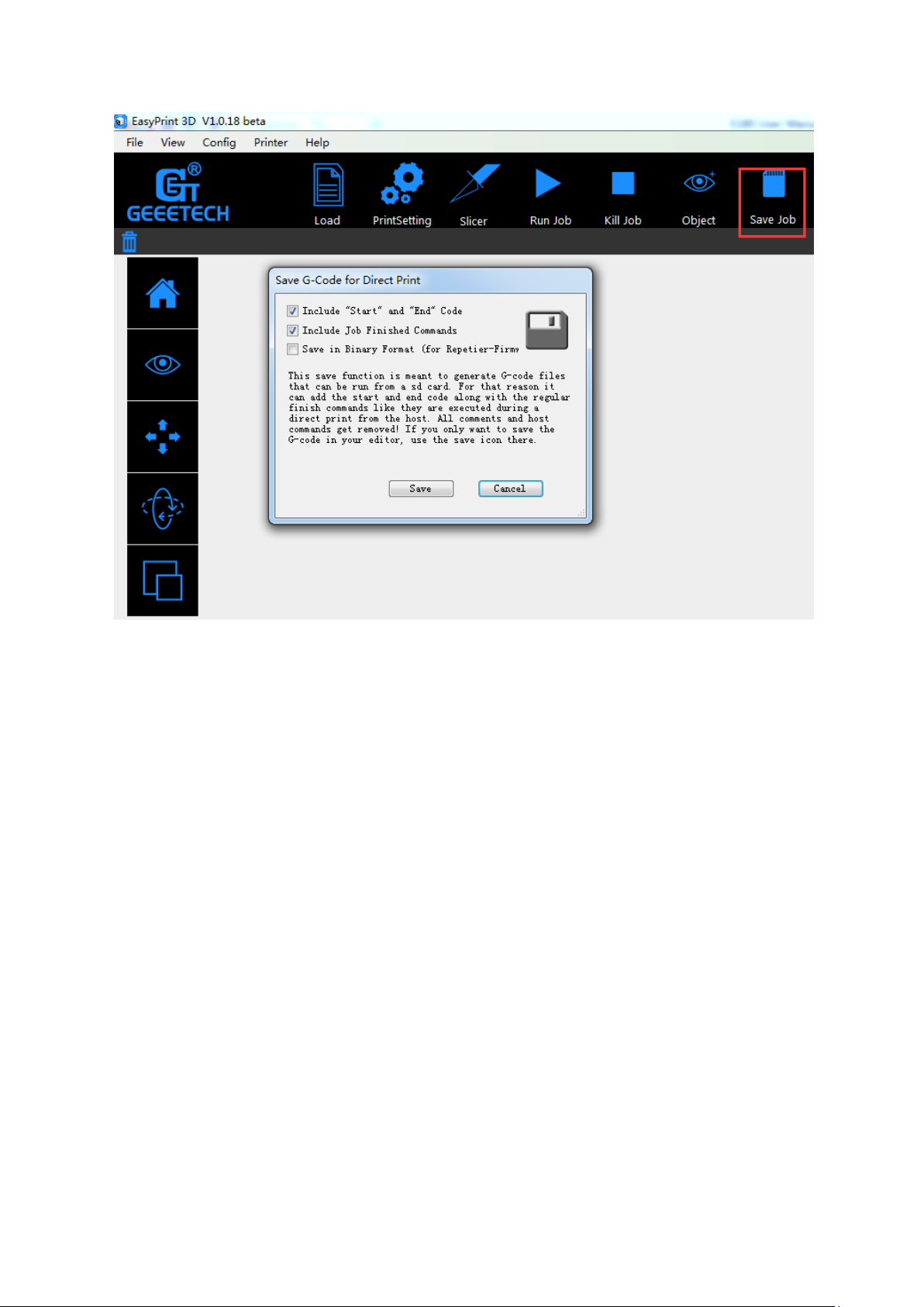
2) Click the [Save] button to save the .Gcode file in TF card, as shown in the picture
below.
Note: The .Gcode file shall be kept in the root file of TF card, or the printer can’t
recognize the file.
28

3) Insert the TF card into the slot on the back of E180.
4) Click the [Printing] button on the home page of the touch screen.
29

5) Choose your 3D model file from the file list and click [Print].
(换图)
7. Printing via Wi-Fi
E180 Cloud 3D printing solution conveniently provides users EasyPrint 3D App to
enjoy free 3D models, just slightly pressing to start your printing journey. Even if you are not
keeping company with your printer, you can control the printer via EasyPrint 3D APP.
EasyPrint 3D App offers the simple, intuitive user interface, full-featured and
easy-to-manage. Paired with built-in Wi-Fi of the printer, you can select the 3D model from
cloud library via App, adjust the printing setting in real time, monitor the printing process and
save the relevant files.
30

EasyPrint 3D App only supports Android system so far. IOS system is under developing.
Please stay tuned.
7.1 Install EasyPrint 3D APP
Download the EasyPrint 3D APP here and install the EasyPrint 3D APP.
www.geeetech.com/firmware/EasyPrint3D_Android.apk
Once finishing installation, enter My Center to register and log in.
Note: As the EasyPrint 3D APP is continuously upgraded, some UI and workflow may
be different, please follow the APP.
7.2 Bind printer to EasyPrint 3D App
Log in and bind the printer. In My Center—My 3D Printer, finish the binding process
following the instructions on App.
31

32

(换图)
Detailed configuration procedures are as follows:
① .In Wi-Fi setting interface on the control panel, choose Wi-Fi button
to enter Wi-Fi interface, as shown in the picture below.
33

②.Turn on Wi-Fi and click the button “Set “to enter the Config mode, as shown in the
picture below.
③.Choose Wi-Fi at the control panel on APP. At the page of pop-up, click the button
“Wi-Fi” to enter Wi-Fi configuration, as shown in the picture below.
34

35

④.Click [Next] to start to detect Wi-Fi built in the printer. If not detected, it will pop up
a prompt “Printer Wi-Fi is not detected”. Click [OK] and again click [Next] to redetect. If
the Wi-Fi is detected, you could see the following picture.
36

⑤ Click [Next] after Wi-Fi hotspot is detected, as shown in the picture below.
37

⑥ Choose one of the available Wi-Fi hotspots. Click [Next], and, if the Wi-Fi needs the
password, the interface will show the Wi-Fi password input box. Just input the correct
password, and then click “[OK]”, as shown in the picture below.
38

⑦. When you succeed in connecting the Wi-Fi, the interface will show that the
configuration is finished, as shown in the picture below.
39

Then the interface returns back to the control panel of the printer. You can see the
prompt, as shown in the picture below.
Click the button“Connect”on control panel, the interface will skip to Wi-Fi interface to
connect with Network. The icon and status bar of Wi-Fi become blue on Wi-Fi interface.
Meanwhile, SSID, IP Address and Server on this interface will display the relevant
information, as shown in the picture below.
40

Go back to App, click “[OK]”to enter the home page. The status on the homepage displays
that the printer is on-line. Till here, the configuration between App and the printer is finished.
Now you can print and control the printing via App.
⑧. If you choose a Wi-Fi hotspot without password, click “Next” and continue your
setting from step ⑦.
8. Specifications of E180
Printing parameters
Print technology: FDM
Build volume: 180x130x130mm
Printing precision:0.05mm
Positioning precision: X/Y:0.11mm. Z: 0.0025mm
Print Speed: 80-110mm/s recommended
Filament diameter: 1.75mm
Nozzle diameter: 0.4mm
Filament supported: PLA
Belts:
Operating system: Windows
41

Control software: EasyPrint 3D
File format: .stl, G-code
Temperature:
Max heated bed temp: About 110 °C
Max extruder temp: About 240°C
Electrical:
Power supply:
Input: 110V-220V
Output:DC24V/15A 360W
Connectivity: Wi-Fi, USB, TF card (support stand-alone printing)
Display screen:3.2 Full color touch screen
Mechanical:
Chassis: Metal plate + injection molding (a portable cantilever type 3D printer)
Build Platform: Aluminum alloy plate
XYZ Rods: Wear-resistant, stainless steel and lead screw (Z axis)
Stepper Motors: 1.8°step angle with 1/16 micro-stepping
Physical Dimensions & Weight
Machine Dimension: 284x130x320 mm
Shipping box Dimension: 320x300x200mm
Machine Net weight: 5kg
Machine shipping weight: 6.5kg
42

9. Contact us
Technical
support
1. There are lots of documents and troubleshooting for MeCreator 2 on our
website. They are good resources if you would like to quickly solve problems
by yourself.
2.If you still can not solve problems yourself even with the help of above files,
you can send e-mail to
technical@geeetech.com,we will reply to you within 24 hours.
Sales
For more products of Geeetech, please visit www.geeetech.com or send e-mail
to sales@geeetech.com
Feedback
In order to improve our products to provide better user experience, please send
your comments and suggestions to Rita.xiang@geeetech.cn. We will appreciate
to hear your valuable suggestions.
43
 Loading...