

Page 1

Rugged Mobile Computing Solutions
S410
USER MANUAL
Page 2

January 2016
TRADEMARKS
The Bluetooth® word mark and logos are registered trademarks owned by Bluetooth
SIG, Inc.
All brand and product names are trademarks or registered trademarks of their
respective companies.
Page 3

NOTE
The information in this manual is subject to change without notice.
For the latest version of the manual, please visit the Getac website at www.getac.com.
Page 4

Page 5

Table of Contents
Chapter 1 Getting Started .............................................................. 1
Getting the Computer Running ........................................... 2
Unpacking .................................................................. 2
Connecting to AC Power ............................................... 3
Turning On and Off the Computer .................................. 4
Taking a Look at the Computer ......................................... 6
Front Components ........................................................ 6
Rear Components ........................................................ 7
Right-Side Components ................................................. 8
Left-Side Components ................................................... 9
Top-open Components ................................................. 10
Bottom Components ..................................................... 12
Chapter 2 Operating Your Computer ............................................ 14
Using the Keyboard ........................................................ 15
Typewriter Keys .......................................................... 15
Cursor-Control Keys .................................................... 15
Numeric Keypad ......................................................... 16
Function Keys ............................................................ 17
Fn Key ..................................................................... 17
Hot Keys .................................................................. 17
Windows Keys ............................................................ 19
Using the Touchpad ....................................................... 20
Touch Gestures for Windows 10 .................................... 21
Configuring the Touchpad ............................................ 22
Using the Touchscreen (Optional) ................................... 23
i
Page 6

Using Multi-touch Gestures .......................................... 24
Using the Tether (Optional) ....................................... 26
Using the Quick Buttons ................................................. 28
Using Network and Wireless Connections ........................... 30
Using the LAN .......................................................... 30
Using the WLAN ........................................................ 31
Using the Bluetooth Feature ......................................... 33
Using the WWAN Feature (Optional) ........................... 35
Using the DVD Drive (Optional) ..................................... 38
Inserting and Removing a Disc..................................... 39
Using the GPS Feature (Optional) ................................... 41
Using the Fingerprint Scanner (Optional) .......................... 42
Enrolling a Fingerprint ................................................. 42
Fingerprint Login ........................................................ 44
Using the Contactless Smart Card Reader (Optional) .......... 45
Chapter 3 Managing Power .......................................................... 47
AC Adapter .................................................................. 48
Battery Pack ................................................................ 49
Charging the Battery Pack ........................................... 49
Initializing the Battery Pack .......................................... 50
Checking the Battery Level .......................................... 50
Battery Low Signals and Actions ................................... 50
Replacing the Battery Pack ........................................... 51
Hot Swapping the Battery Pack (Optional) .................... 53
Power-Saving Tips ........................................................ 55
Chapter 4 Expanding Your Computer ........................................... 56
Connecting Peripheral Devices .......................................... 57
Connecting a USB Device ........................................... 57
Connecting a Device for USB Charging (Optional) .......... 58
Connecting a Monitor .................................................. 59
Connecting a Serial Device (Optional) .......................... 60
Connecting an Audio Device ........................................ 60
Using Storage and Expansion Cards .................................. 61
Using Storage Cards ................................................... 61
ii
Page 7

Using Smart Cards .................................................... 62
Using ExpressCards (Optional) .................................... 63
Using PC Cards (Optional) ........................................ 64
Changing or Replacing ................................................... 65
Replacing the Hard Disk Drive ..................................... 65
Chapter 5 Using BIOS Setup ......................................................... 66
When and How to Use .................................................. 67
Menu Descriptions ......................................................... 68
Information Menu ....................................................... 68
Main Menu ............................................................... 68
Advanced Menu ......................................................... 69
Security Menu ............................................................ 71
Boot Menu ............................................................... 72
Exit Menu ................................................................ 72
Chapter 6 Using Getac Software ................................................... 74
G-Manager .................................................................. 75
Quick Button Definition Utility ........................................... 77
Chapter 7 Care and Maintenance .................................................. 79
Protecting the Computer .................................................. 80
Using an Anti-Virus Strategy ....................................... 80
Using the Cable Lock ................................................. 80
Taking Care of the Computer ........................................... 81
Location Guidelines ...................................................... 81
General Guidelines ...................................................... 81
Cleaning Guidelines .................................................... 82
Battery Pack Guidelines .............................................. 82
Touchscreen Guidelines ............................................... 84
When Traveling ............................................................. 85
Chapter 8 Troubleshooting .......................................................... 86
Preliminary Checklist ....................................................... 87
Solving Common Problems .............................................. 88
Battery Problems ........................................................ 88
Bluetooth Problems ..................................................... 88
iii
Page 8

Display Problems ....................................................... 89
DVD Drive Problems .................................................. 89
Hardware Device Problems .......................................... 90
Hard Disk Drive Problems ........................................... 90
Keyboard and Touchpad Problems .................................. 91
LAN Problems ............................................................ 91
Power Management Problems ....................................... 92
Software Problems ..................................................... 92
Sound Problems ........................................................ 92
Startup Problems ....................................................... 93
WLAN Problems ........................................................ 93
Other Problems ......................................................... 95
Resetting the Computer .................................................. 96
System Recovery ........................................................... 97
System Restore, Recovery, or Reset (for Windows 10
Models) .................................................................. 97
System Recovery (a Tool for Windows 7 Models) ......... 97
Using the Driver Disc ................................................... 100
Appendix A Specifications.............................................................. 101
Appendix B Regulatory Information ............................................... 103
On the Use of the System .......................................... 104
Class B Regulations .................................................. 104
Safety Notices .......................................................... 105
On the Use of the RF Device ....................................... 108
USA and Canada Safety Requirements and Notices......... 108
European Union CE Marking and Compliance Notices ...... 110
User Notification of Take-back Service ..............................112
ENERGY STAR 6.1 .......................................................113
Battery Recycling ...........................................................115
iv
Page 9

Chapter 1
Congratulations on purchasing this rugged computer.
This chapter first tells you step by step how to get the computer up and running.
Then, you will find a section briefly introducing the external components of the
computer.
1
Page 10
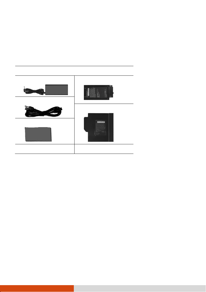
S410 notebook computer
AC adapter
Main battery pack
AC power cord
Second battery pack*
Screen cleaning cloth
Driver disc
Document(s)
Getting the Computer Running
Unpacking
After unpacking the shipping carton, you should find these standard items:
* Select models only
Inspect all the items. If any item is damage or missing, notify your dealer immediately.
2
Page 11
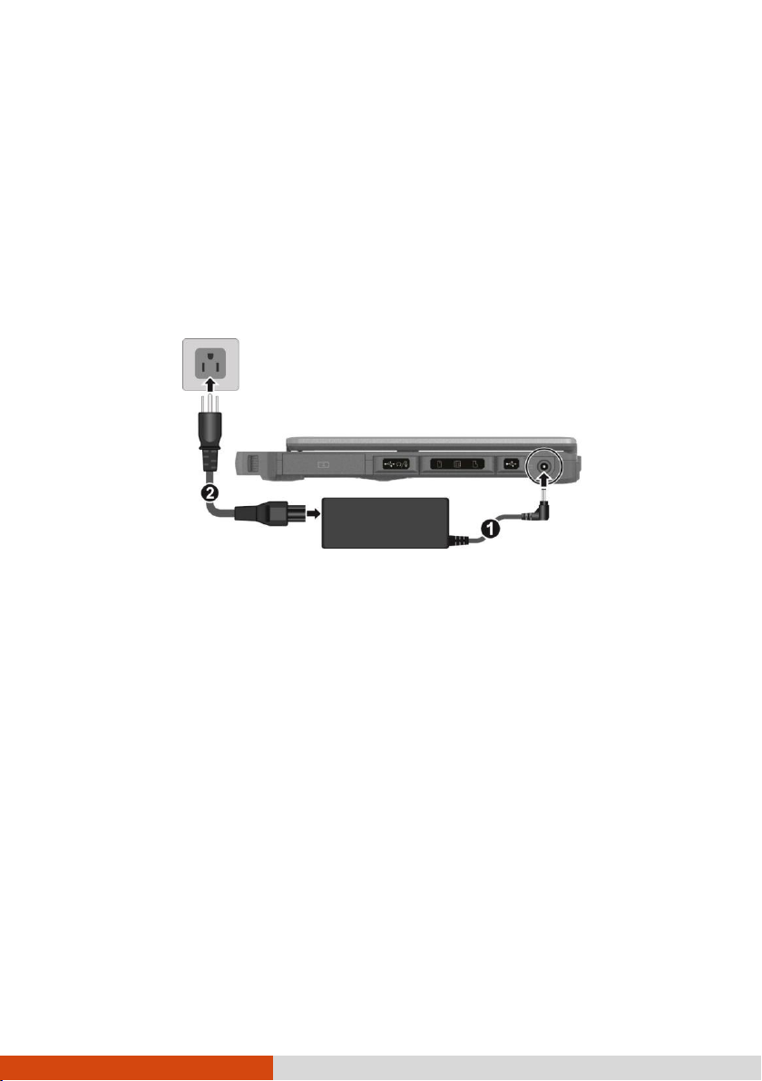
Connecting to AC Power
It is suggested that you use AC power when starting up the computer for the very
first time.
1. Plug the DC cord of the AC adapter to the power connector of the computer
().
2. Plug the female end of the AC power cord to the AC adapter and the male
end to an electrical outlet ().
3. Power is being supplied from the electrical outlet to the AC adapter and onto
your computer. Now, you are ready to turn on the computer.
CAUTION: Use only the AC adapter included with your computer.
Using other AC adapters may damage the computer.
NOTE: When the AC adapter is connected, it also charges the
battery pack. For information on using battery power, see
Chapter 3.
3
Page 12
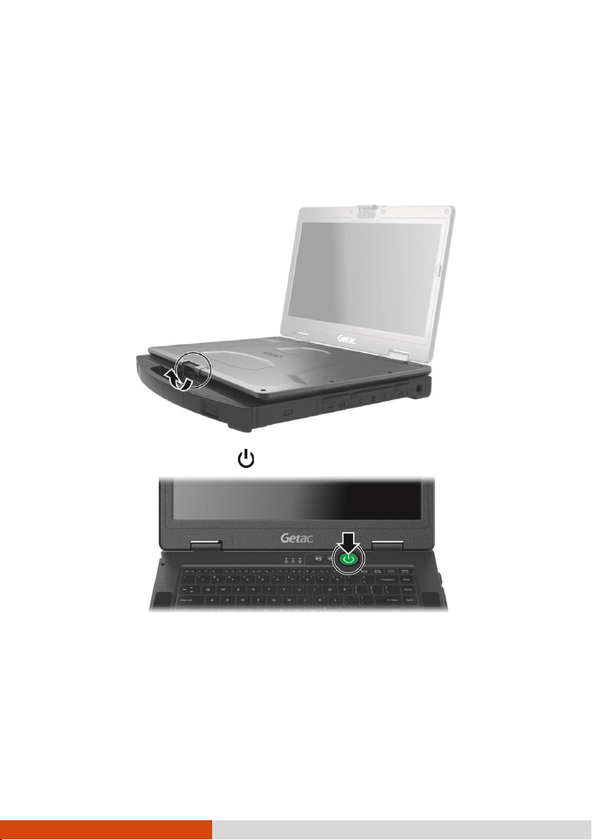
Turning On and Off the Computer
Turning On
1. Open the top cover by pulling the cover latch and lifting up the cover. You
can tilt the cover forward or backward for optimal viewing clarity.
2. Press the power button (
). The Windows operating system should start.
4
Page 13
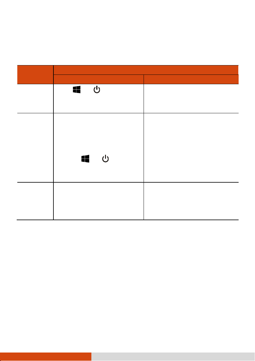
To...
Do this...
Windows 10
Windows 7
Power off
(Shutdown)
Click Power Shut
down.
Use the Windows Start menu in the
lower left and follow the shutdown
procedure.
Sleep
Use one of these methods:
Press the power button.*
Close the top cover.*
Press Fn + F12.*
Click Power
Sleep.
Use one of these methods:
Press the power button.*
Close the top cover.*
Press Fn + F12.*
Use the Windows Start menu to
put the computer in Sleep
mode.
Hibernate
By default, this option is not shown
in the Start menu. If you want to
use the feature, set up accordingly
in Windows settings.
Use the Windows Start menu to put
the computer in Hibernation mode.
Turning Off
When you finish a working session, you can stop the system by turning
power or leaving it in Sleep or Hibernation mode:
off the
* “Sleep” is the default result of the action. You can change what the action
does through Windows settings.
5
Page 14
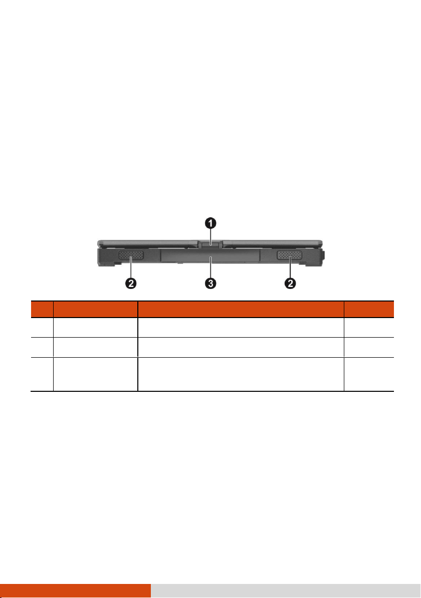
Ref
Component
Description
See Also
Top Cover Latch
Locks the top cover.
P. 4
Stereo Speaker
Sends out sound and voice from the computer.
Handle
Provides a convenient way to carry the
computer.
Taking a Look at the Computer
NOTE: Depending on the specific model you purchased, the color
and look of your model may not exactly match the graphics shown
in this document.
CAUTION: You need to open the protective covers to access the
connectors. When not using a connector, make sure to close the
cover completely for water- , dust-, and fire-proof integrity.
(Engage the locking mechanism if existing.)
Front Components
6
Page 15

Ref
Component
Description
See Also
HDMI Connector
Connects a HDMI monitor or TV set.
P. 59
USB 3.0 Port
Connects a USB device, such as a USB flash
disk, printer, digital camera, joystick, and
more.
P. 57
RJ-45 Connector
Connects the LAN cable.
P. 30
Optional I/O
Connector
Depending on the model, the component can
be one of the following:
None
RJ-45 Connector
Connects the LAN cable (for LAN 2).
P. 30
PowerShare USB Port
Can be used to charge mobile devices.
P. 58
VGA Connector
(optional)
Connects an external display monitor.
P. 59
or
RS232 Serial
Connector
(optional)
Connects a serial mouse o r serial
communication device.
RS232 Serial
Connector
(optional)
Connects a serial mouse o r serial
communication device.
P. 60
Kensington Lock
Locks the computer to a stationary object for
security.
P. 80
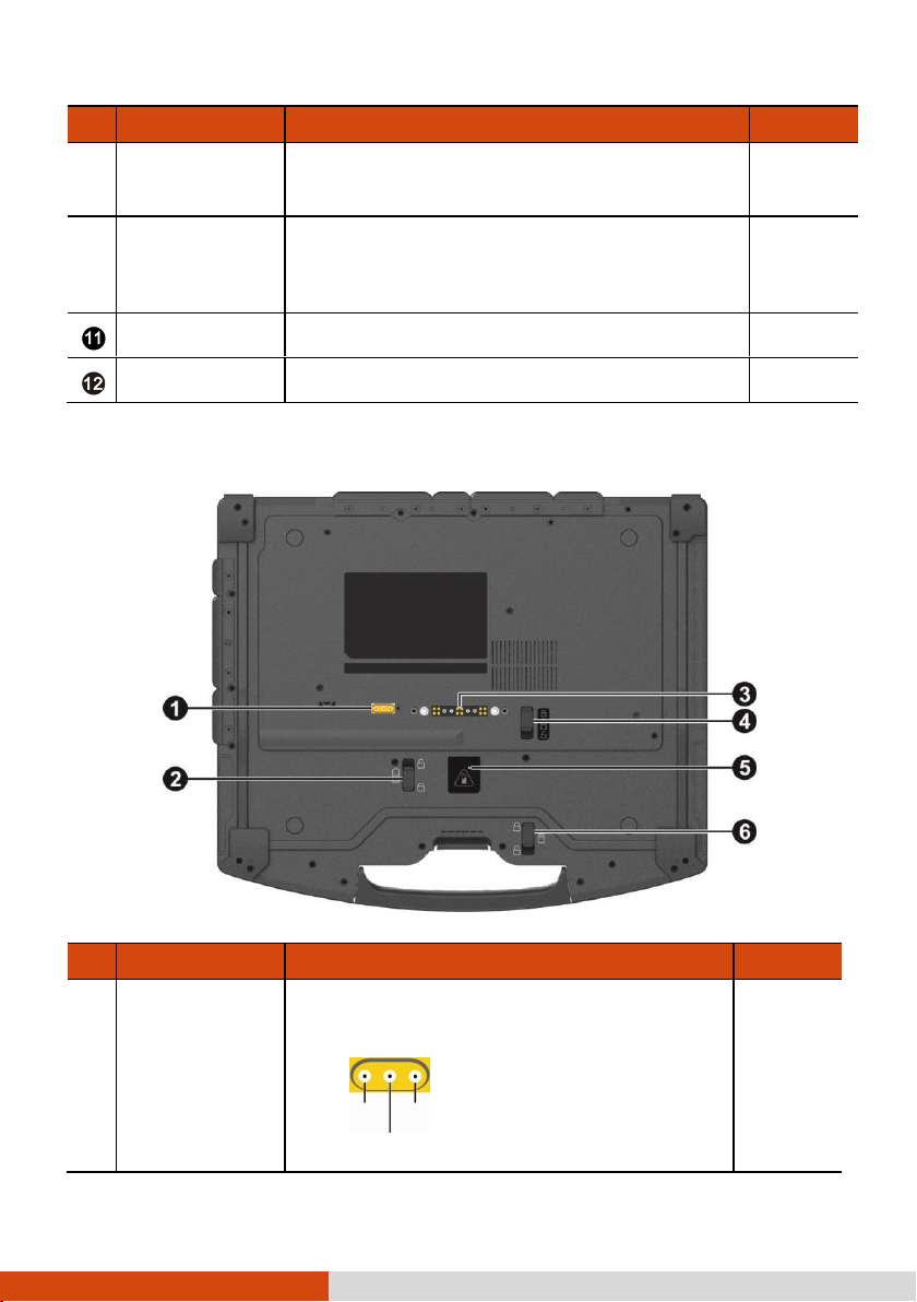
Rear Components
7
Page 16
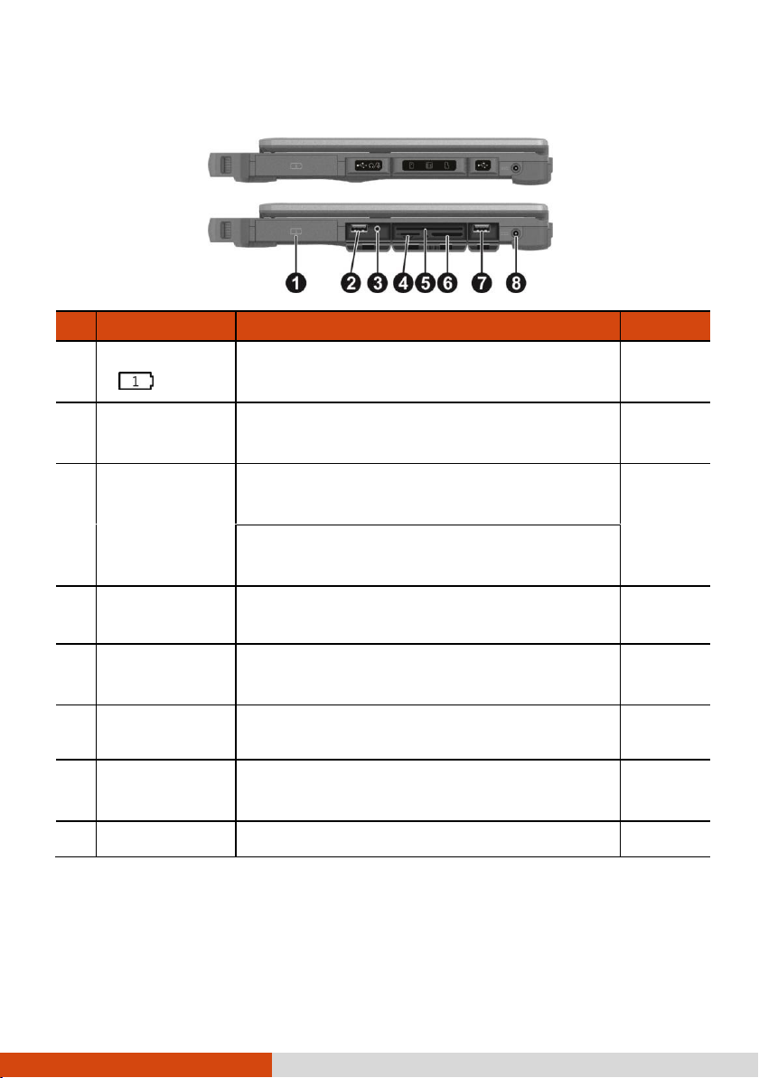
Ref
Component
Description
See Also
Battery Pack
( )
Supplies power to your computer when external
power is not connected.
P. 49
USB 2.0 Port
Connects a USB device, such as a USB flash
disk, printer, digital camera, joystick, and more.
P. 57
Combo Audio
Connector
Connects a set of headphones or external
speakers with amplifier
P. 60
Supports a headset microphone with 4-pole
TRRS 3.5mm jack.
SIM Card Slot
(optional)
Accepts a SIM card for models having the WWAN
module.
P. 35
Smart Card
Reader
Accepts a smart card for additional security
feature.
P. 61
Storage Card
Reader
Accepts an SD card for removable storage media.
P. 61
USB 3.0 Port
Connects a USB device, such as a USB flash
disk, printer, digital camera, joystick, and more.
P. 57
Power Connector
Connects the AC adapter.
P. 3
Right-Side Components
8
Page 17

Ref
Component
Description
See Also
Stylus Slot
For storing the stylus (optional).
P. 23
Tether Hole
Stylus tethered to this hole.
P. 26
Multi-purpose Bay
Depending on the model, the component can
be one of the following:
None
Second Battery
Pack
( )
Supplies power to your computer when external
power is not connected.
P. 49
Super Multi Drive
Accepts a compact disc for installing or loading
software, accessing data, and playing
music/video.
P. 38
PC Card Slot
Accepts a PC card for additional functions.
P. 64
ExpressCard Slot
Accepts an ExpressCard for additional functions.
P. 63
Hard Disk Drive
Is the storage device that contains the operating
system, software programs, and data files.
P. 65
Left-Side Components
9
Page 18
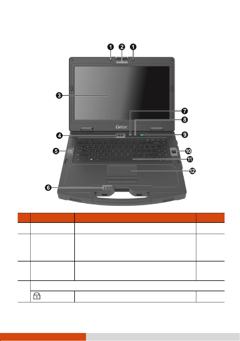
Ref
Component
Description
See Also
Microphone
Receives sound and voice for the computer.
Camera Lens
(optional)
Allows you to use the camera function. When the
camera lens is in use, the LED beside it lights
up.
LCD Screen
Displays the output of the computer. May include
the optional touchscreen feature.
P. 23
Indicators
Num Lock
Lights green when Num Lock is on.
P. 16
Top-open Components
10
Page 19
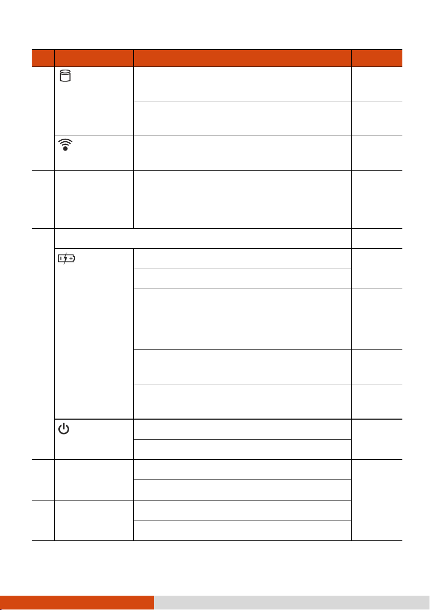
Ref
Component
Description
See Also
Hard Disk
Blinks green when computer is reading / writing
data to the hard disk
Lights red when the optional hard disk heater is
on.
P. 93
RF (Radio
Frequency)
Lights green when the RF radio of any RF feature
(WLAN/Bluetooth/WWAN) is on.
Contactless
Smart Card
Reader
(optional)
Serves as an RFID reader/writer and an NFC
reader.
P. 45
Indicators
Battery
Lights amber when the battery is being charged.
P. 49
Lights green when battery charging is completed.
Blinks green to indicate the battery’s built-in high
temperature protection mechanism is activated.
CAUTION: Do not remove the battery
during this period.
Blinks red when the battery’s capacity is below
10 %.
P. 50
Blinks amber when the battery is in an abnormal
condition.
Power
Lights green when computer is on.
Blinks green when computer is in Sleep mode.
P1 Button
Toggles Blackout mode on or off.
P. 26
Can be changed to a different function.
P2 Button
Toggles the sunlight-readable mode on or off.
Can be changed to a different function.
11
Page 20
Ref
Component
Description
See Also
Power Button
Turns the power on or off (Sleep mode by
default).
P. 4
Fingerprint
Scanner
(optional)
Serves as the fingerprint verification, preventing
unauthorized access to your computer.
P. 38
Keyboard
Serves as the data input device of the computer.
P. 15
Touchpad
Serves as the pointing device of the computer.
P. 20
Ref
Component
Description
See Also
Antenna Passthrough
(optional)
Connects to the docking station for using
external WWAN/WLAN/GPS antenna.
WWAN
GPS
WLAN
Bottom Components
12
Page 21

Battery Latch
( )
Locks the main battery pack in place.
P. 51
Ref
Component
Description
See Also
Docking
Connector
Connects to the office or vehicle dock
(purchased separately).
Battery Latch
( )
Locks the second battery pack in place.
P. 51
Battery Hot
Swapping
Indicator
Lights up if you unlock the battery latch while
operating the computer on battery power. The
indicator is intended to inform whether you can
safely hot swap the battery pack.
NOTE: This indicator works only if
your model has the second battery
pack and/or bridge battery.
P. 53
Green light: It is safe to hot swap the battery
pack.
Red light: Hot swapping is not allowed.
Blinking red light: The computer is entering
Hibernation mode.
Hard Disk Drive
Latch
Locks the hard disk drive in place.
P. 65
13
Page 22

Chapter 2
This chapter provides information about the use of the computer.
If you are new to computers, reading this chapter will help you learn the operating
basics. If you are already a computer user, you may choose to read only the parts
containing information unique to your computer.
CAUTION:
Do not expose your skin to the computer when operating it
in a very hot or cold environment.
The computer can get uncomfortably warm when you use it in
high temperatures. As a safety precaution in such a
circumstance, do not place the computer on your lap or touch
it with your bare hands for extended periods of time.
Prolonged body contact can cause discomfort and potentially
a burn.
14
Page 23

Using the Keyboard
Your keyboard has all the standard functions of a full-sized computer keyboard plus
an
Fn key added for specific functions.
The standard functions of the keyboard can be further divided into four major
categories:
Typewriter keys
Cursor-control keys
Numeric keys
Function keys
Typewriter Keys
Typewriter keys are similar to the keys on a typewriter. Several keys are added
such as the
Ctrl, Alt, Esc, and lock keys for special purposes.
The Control (
keys for program-specific functions. The Escape (
stopping a process. Examples are exiting a program and canceling a command.
The function depends on the program you are using.
Ctrl) / Alternate (Alt) key is normally used in combination with other
Esc) key is usually used for
Cursor-Control Keys
Cursor-control keys are generally used for moving and editing purposes.
15
Page 24
NOTE: The word “cursor” refers to the indicator on the screen
that lets you know exactly where on your screen anything you
type will appear. It can take the form of a vertical or
horizontal line, a block, or one of many other shapes.
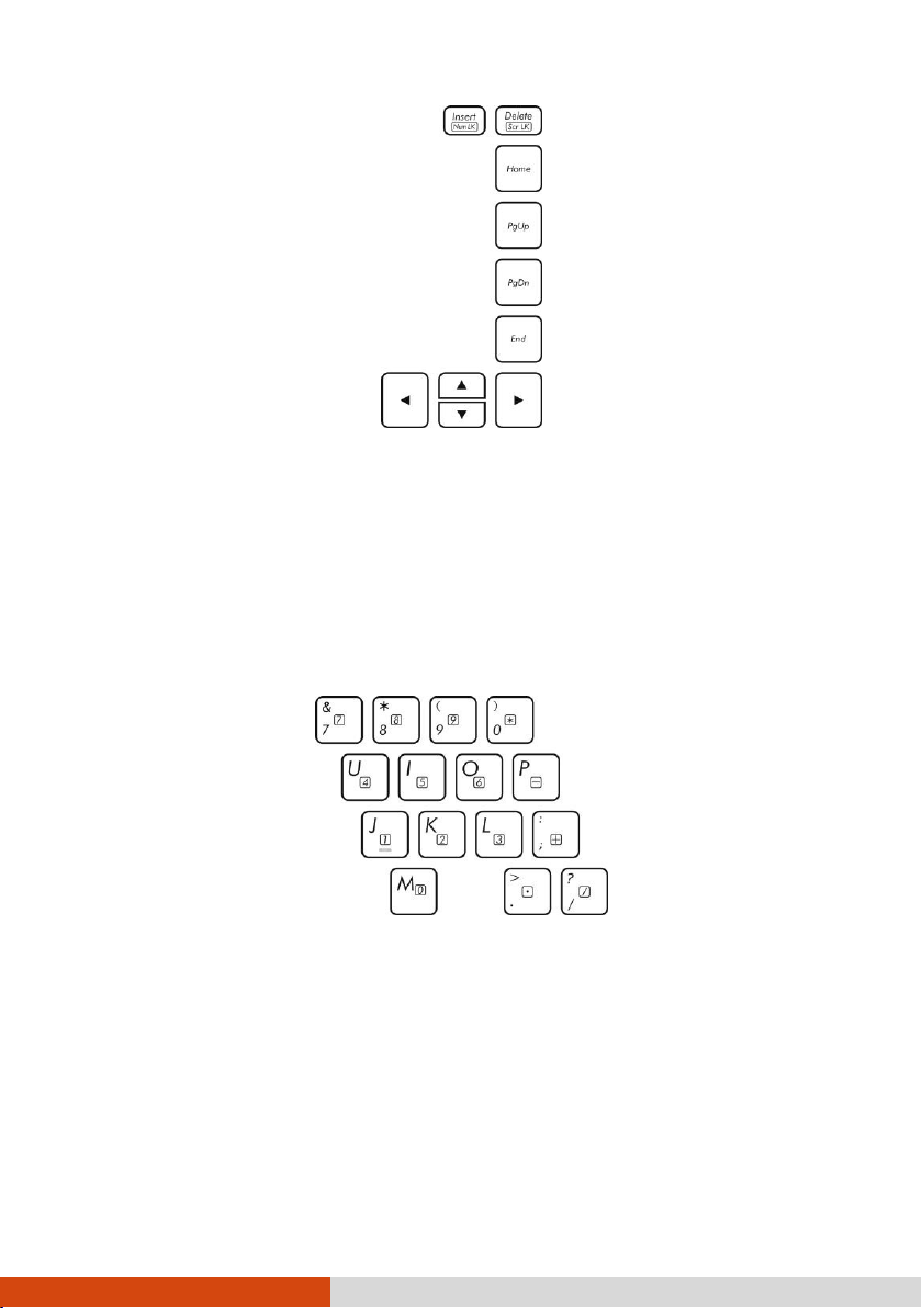
Numeric Keypad
A 15-key numeric keypad is embedded in the typewriter keys as shown next:
Numeric keys facilitate entering of numbers and calculations. When Num Lock is
on, the numeric keys are activated; meaning you can use these keys to enter
numerals.
NOTE:
When the numeric keypad is activated and you need to type
the English letter in the keypad area, you can turn Num Lock
off or you can press
Num Lock off.
Fn and then the letter without turning
16
Page 25

Key
Description
Switches the keyboard backlight off or on (with 4-level
brightness). *
Switches the RF (radio frequency) radio on and off.
When off, all wireless modules (such as WLAN, Bluetooth, and
WWAN) cannot be used. When on, individual settings of the module
work.
Decreases the sound volume.
Some software may not be able to use the numeric keypad on
the computer. If so, use the numeric keypad on an external
keyboard instead.
The Num Lock key can be disabled. (See “Main Menu” in Chapter 5.)
Function Keys
On the top row of the keys are the function keys: F1 to F12. Function keys are
multi-purpose keys that perform functions defined by individual programs.
Fn Key
The Fn key, at the lower left corner of the keyboard, is used with another key
to perform the alternative function of a key. To perform a desired function, first press
and hold
Fn, then press the other key.
Hot Keys
Hot keys refer to a combination of keys that can be pressed any time to activate
special functions of the computer. Most hot keys operate in a cyclic way. Each
time a hot key combination is pressed, it shifts the corresponding function to the
other or next choice.
You can easily identify the hot keys with the icons imprinted on the keytop. The
hot keys are described next.
17
Page 26
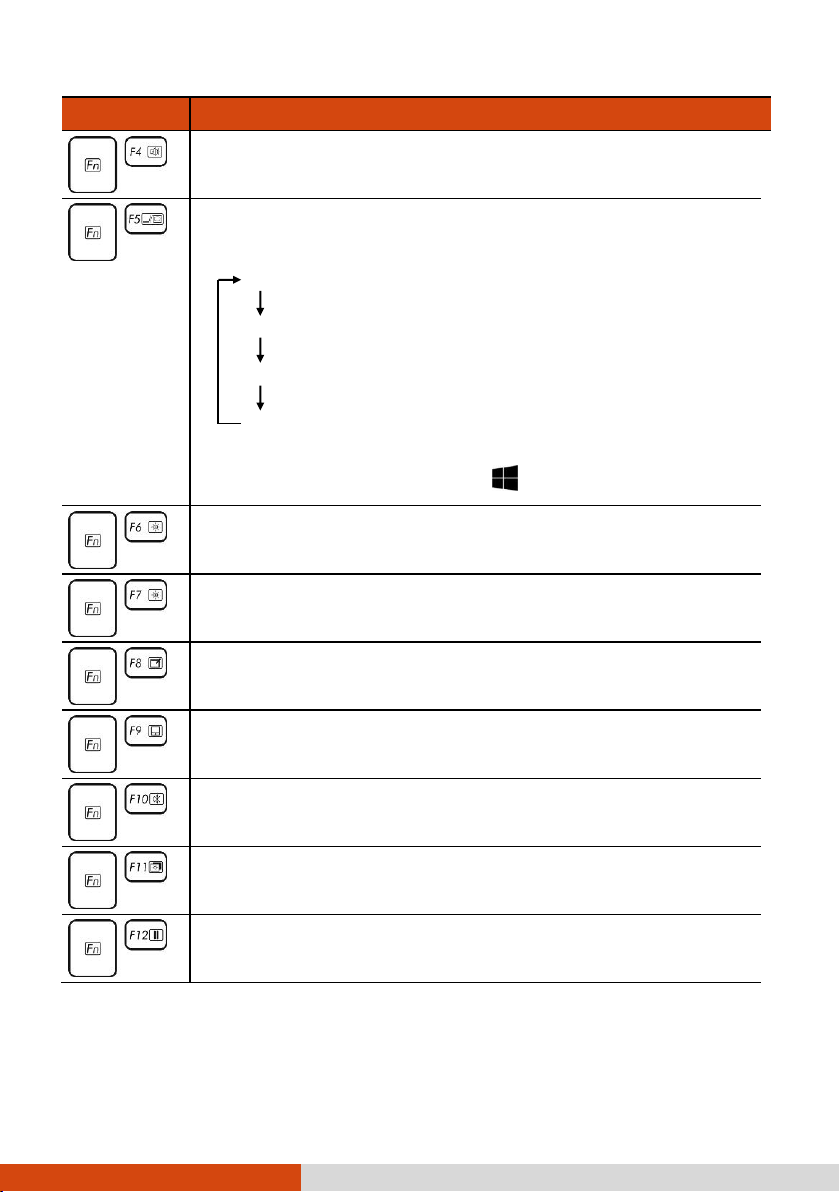
Key
Description
Increases the sound volume.
Switches the display output to the next choice if an external display
is connected. Choices are:
LCD only
LCD + External display (Duplicate)
LCD + External display (Extend)
External display only
The hot keys are equivalent to
Windows logo key + P.
Decreases the LCD brightness.
Increases the LCD brightness.
Switches the touchscreen off or on.*
Switches the touchpad off or on.
Switches the system sound output off (mute) or on.
Switches the display backlight off or on.
Serves as the sleep button that you can define with Windows’
Power Options.
TABLE NOTE: * means “select models only.”
18
Page 27

Windows Keys
The keyboard has two keys that perform Windows-specific functions: Windows
Logo key and Application key.
The Windows Logo key opens the
specific functions when used in combination with other keys. The Application
key usually has the same effect as a right mouse click.
Start menu and performs software-
19
Page 28
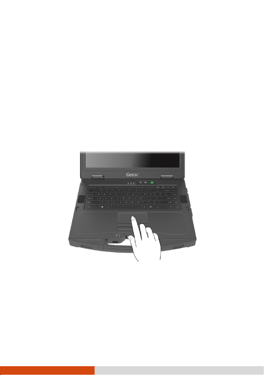
Using the Touchpad
CAUTION: Do not use a sharp object such as a pen on the touchpad.
Doing so may damage the touchpad surface.
NOTE:
You can press
For optimal performance of the touchpad, keep your fingers
and the pad clean and dry. When tapping on the pad, tap
lightly. Do not use excessive force.
The touchpad is a pointing device that allows you to communicate with the computer
by controlling the location of the pointer on the screen and making selection with
the buttons.
Fn+F9 to toggle the touchpad on or off.
The touchpad consists of a rectangular pad (work surface) and a left and right
buttons. To use the touchpad, place your forefinger or thumb on the pad. The
rectangular pad acts like a miniature duplicate of your display. As you slide your
fingertip across the pad, the pointer (also called cursor) on the screen moves
accordingly. When your finger reaches the edge of the pad, simply relocate yourself
by lifting the finger and placing it on the other side of the pad.
20
Page 29

Term
Action
Point
Move your finger on the pad until the cursor points to the selection
on the screen.
Click
Press and release the left button.
–or–
Tap gently anywhere on the pad.
Double-click
Press and release the left button twice in quick succession.
–or–
Tap twice on the pad rapidly.
Drag and
drop
Press and hold the left button, then move your finger until you
reach your destination (drag). Finally, release the button (drop)
when you finish dragging your selection to the destination. The
object will drop into the new location.
–or–
Gently tap twice on the pad and on the second tap, keep your
finger in contact with the pad. Then, move your finger across the
pad to drag the selected object to your destination. When you lift
your finger from the pad, the selected object will drop into place.
Here are some common terms that you should know when using the touchpad:
TABLE NOTE: If you swap the left and right buttons, “tapping” on the touchpad as
an alternative method of pressing the left button will no longer be valid.
Touch Gestures for Windows 10
The touchpad supports touch gestures for Windows 10 such as on-finger scrolling,
two-finger scrolling, pinch zoom, rotating, and others. For detailed information, go
to Settings Devices Mouse & touchpad Additional mouse options Device
Settings Settings.
21
Page 30

Configuring the Touchpad
You may want to configure the touchpad to suit your needs. For example, if you
are a left-handed user, you can swap the two buttons so that you can use the
right button as the left button and vice versa. You can also change the size of
the on-screen pointer, the speed of the pointer, and so on.
To configure the touchpad, go to
Windows 10) or.Control Panel Mouse (in Windows 7).
Settings Devices Mouse & touchpad (in
22
Page 31

Term/Action
Equivalent Mouse
Function
Tap: Touch the screen once.
Click/Point
Double-tap: Touch the screen twice rapidly.
Double-click
Tap and hold: Tap and hold until a popup menu appears.
Right-click
Drag: Hold the stylus (or finger) on the screen and drag
across the screen until reaching your destination.
Drag
Using the Touchscreen (Optional)
NOTE: You can press
CAUTION: Do not use a sharp object such as a ballpoint pen or
pencil on the touchscreen. Doing so may damage the touchscreen
surface. Use your finger or the included stylus.
Select models have a capacitive touchscreen. This type of touchscreen responds
to objects that have conductive properties, such as fingertips and a capacitive-tipped
stylus. You can navigate on the screen without using a keyboard, touchpad, or mouse.
By default settings, your touchscreen responds best to fingertips. If you prefer using
a capacitive-tipped stylus (purchased separately) or if you are wearing gloves, you
should change the touchscreen settings to suit your scenario. (Use the G-Manager
program and select the Touch Screen tab to set up.)
The following table shows how you use the touchscreen to obtain equivalent mouse
functions.
Fn+F8 to toggle the touchscreen on or off.
23
Page 32

Gestures
Actions
( = finger down; = finger up)
Descriptions
Pan
(Scroll)
or
Drag 1 or 2 fingers up or down.
Use panning to see
another part of a page that
has scroll bars.
Zoom
(Pinch)
Move two fingers apart/toward each
other.
Use zooming to make an
item (a photo for
example) on the screen
larger or smaller. The
gesture works in
applications that support
mouse wheel zooming.
Rotate
or
Move two fingers in opposing directions.
-orUse one finger to pivot around another.
Use rotating to move a
picture or other item on
the screen in a circular
direction (clockwise or
counterclockwise). The gesture
works in applications that
support the specific
gesture.
Using Multi-touch Gestures
You can interact with your computer by placing two fingers on the screen. The
movement of the fingers across the screen creates “gestures,” which send commands
to the computer.
Here are the multi-touch gestures that you can use:
24
Page 33

Gestures
Actions
( = finger down; = finger up)
Descriptions
Press and
Tap
Press on target and tap using a second
finger.
Use press and tap to
access the shortcut menu.
Twofinger Tap
Tap two fingers at the same time (where
the target is in the midpoint between the
fingers).
The function is defined by
applications that support
the specific gesture.
Flicks
Make quick drag gestures in the desired
direction.
Flick left or right to
navigate back and forward
in a browser and other
applications. The gesture
works in most applications
that support back and
forward.
25
Page 34

Using the Tether (Optional)
You can purchase a stylus and tether for your computer model. Use the tether to
attach the stylus to the computer.
1. Insert one of the tether’s loop ends through the hole of the stylus (as indicated
by below). Then, insert the other end through the first loop (as indicated
by below) and pull it tight.
2. Insert the other loop end to the hook on the computer (as indicated by
below). Then, insert the stylus end through the loop (as indicated by below)
and pull it tight.
3. When not in use, store the stylus in the stylus slot.
CAUTION: Be careful the tether does not get in the way when you
open or close the DVD tray (if your model has a DVD drive) and
when you connect the computer to the office or vehicle dock.
26
Page 35

27
Page 36

Button
Description
Remarks
P1
Toggles Blackout mode on or off.
In Blackout mode, the LCD backlight, keyboard/button
backlight, and LED indicators are all turned off; and the
sound is muted.
To bring the computer out of Blackout mode, press the same
button again or the power button.
Default
function
Can start a program based on your settings. (See “Quick
Button Definition Utility” in Chapter 6 for more information.)
Alternative
functions
Can serve as “Emergency” button if set accordingly in the
BIOS Setup program. (For setup information, see
“Advanced Menu” in Chapter 5.)
P2
Toggles the sunlight-readable mode on or off.
In sunlight-readable mode, the LCD brightness is increased
to the highest level. The mode automatically ends when the
brightness setting is changed, the computer resumes from
Sleep/Hibernation mode, or the computer is restarted.
Default
function
Using the Quick Buttons
The Quick Buttons allow you to quickly start a program or activate a function.
28
Page 37

Button
Description
Remarks
P2
Selects an ECO mode. (For setup information, see
“Advanced Menu” in Chapter 5.)
Pressing the button brings up the ECO menu as shown
below:
Select a mode before the ECO menu disappears. You can
select a mode by pressing the same button or the arrow
key. The ECO mode will return to the default Off setting
when AC power is connected, any power related setting is
changed, the computer resumes from Sleep/Hibernation
mode, or the computer is restarted.
Each ECO mode (Quick, Power Saving, or Work) is a
combination of power settings that results in different power
consumptions. (You can use the G-Manager program to
configure the ECO modes. See “G-Manager” in Chapter
6.)
NOTE: The button works only when using battery
power.
Alternative
functions
Can start a program according to your settings. (See “Quick
Button Definition Utility” in Chapter 6 for more information.)
ECO Me nu
ECO Off
Quick Mode
Power Saving
Work Mode
29
Page 38

LAN2
Using Network and Wireless
Connections
Using the LAN
The internal 10/100/1000Base-T LAN (Local Area Network) module allows you
to connect your computer to a network. It supports data transfer rate up to 1000
Mbps.
Select models have a second LAN module so you can connect to two networks at
the same time.
NOTE: LAN2 module implements DSM (Deep Slumber Mode) to save
battery power. Power is supplied to the LAN module only when
the LAN cable is connected. This means the LAN module will not
appear in Windows’ Device Manager if the LAN cable is not
connected and will appear if the cable is connected.
30
Page 39

WLAN
WLAN
auxiliary antenna
Using the WLAN
The WLAN (Wireless Local Area Network) module supports IEEE 802.11ac,
compatible with 802.11a/b/g/n.
NOTE: Do not block the antenna area.
Turning On/Off the WLAN Radio
To turn on the WLAN radio:
1. Make sure that the Airplane mode is switched off. You can control the Airplane
2. If you have previously turned off the WLAN radio, use one of the below methods
mode using one of the below methods.
Press Fn+F1.
For Windows 10: Click Settings Network & Internet Airplane
mode. Slide the Airplane mode switch to the Off position.
to turn it on.
For Windows 10: Click Settings Network & Internet Wi-Fi. Slide
the Wi-Fi switch to the On position.
For Windows 7: Use either Windows Mobility Center or Getac Quick Bar. To
open Getac Quick Bar, right-click the Getac Utility icon on Windows
31
Page 40

taskbar and select Quick Bar. Click the WLAN button in the Quick Bar (an
X over the button means the radio is currently off).
To turn off the WLAN radio:
You can turn off the WLAN radio the same way you turn it on.
If you want to turn off all wireless radio, slide the RF switch to the
OFF position.
Connecting to a WLAN Network
1. Make sure that the WLAN function is enabled (as described above).
For Windows 10: Click the network icon in the lower right of the task bar.
2.
For Windows 7: Click the Wireless Network icon on the taskbar. (An orange
light in the icon indicates connections are available.)
3. In the list of available wireless networks, click a network, and then click
4. Some networks require a network security key or passphrase. To connect to
one of those networks, ask your network administrator or Internet service provider
(ISP) for the security key or passphrase.
For more information on setting a wireless network connection, refer to Windows
online help.
NOTE: You can use Intel® PROSet Wireless to take full advantage
of the Wi-Fi capabilities of your computer. See the Help of the
utility for instructions.
Connect.
32
Page 41

Bluetooth
main antenna
Bluetooth
auxiliary antenna
Using the Bluetooth Feature
The Bluetooth technology allows short-range wireless communications between
devices without requiring a cable connection. Data can be transmitted through walls,
pockets and briefcases as long as two devices are within range.
NOTE: Do not block the antenna area.
Turning On/Off the Bluetooth Radio
To turn on the Bluetooth radio:
1. Make sure that the Airplane mode is switched off. You can control the Airplane
mode using one of the below methods.
Press Fn+F1.
For Windows 10: Click Settings Network & Internet Airplane
2. If you have previously turned off the Bluetooth radio, use one of the below
methods to turn it on.
For Windows 10: Click Settings Devices Bluetooth. Slide the
mode. Slide the Airplane mode switch to the Off position.
Bluetooth switch to the On position.
33
Page 42

For Windows 7: Use Getac Quick Bar. To open Getac Quick Bar, right-click
the Getac Utility icon on Windows taskbar and select Quick Bar. Click
the Bluetooth button in the Quick Bar (an X over the button means the
radio is currently off).
To turn off the Bluetooth radio:
You can turn off the Bluetooth radio the same way you turn it on.
If you want to turn off all wireless radio, slide the RF switch to the OFF position.
Connecting to another Bluetooth Device
1. Make sure that the Bluetooth function is enabled (as described above).
2. Make sure that the target Bluetooth device is turned on, discoverable and within
close range. (See the documentation that came with the Bluetooth device.)
For Windows 10: Click Settings Devices Bluetooth.
3.
For Windows 7: Right-click the Bluetooth icon
a Device.
4. Select the device you want to connect from the search results.
5. Depending on the type of Bluetooth device that you want to connect to, you
will need to enter the pertinent information.
For detailed information on using the Bluetooth feature, see Windows’ online Help.
34
on Windows taskbar. Click Add
Page 43

WWAN
WWAN
auxiliary antenna
Using the WWAN Feature (Optional)
A WWAN (Wireless Wide Area Network) uses mobile telecommunication cellular
network technologies to transfer data. The WWAN module of your computer supports
3G and 4G LTE.
NOTE:
Your model only supports data transmission; voice
transmission is not supported.
Do not block the antenna area.
Installing a SIM Card
1. Turn off the computer and disconnect the AC adapter.
2. Open the cover of the SIM card slot.
3. Insert the SIM card into the slot. Make sure the golden contact area on the
card is facing upward and the beveled corner on the SIM card facing inward.
35
Page 44

4. Close the cover.
Turning On/Off the WWAN Radio
To turn on the WWAN radio:
1. Make sure that the Airplane mode is switched off. You can control the Airplane
mode using one of the below methods.
Press Fn+F1.
For Windows 10: Click Settings Network & Internet Airplane
mode. Slide the Airplane mode switch to the Off position.
2. If you have previously turned off the WWAN radio, use one of the below methods
to turn it on.
Use the WWAN utility.
For Windows 10: Click Settings Network & Internet Airplane
mode. Slide the Cellular switch to the On position.
For Windows 7: Use Getac Quick Bar. To open Getac Quick Bar, right-click
the Getac Utility icon on Windows taskbar and select Quick Bar. Click
the WWAN button in the Quick Bar (an X over the button means the radio
is currently off).
To turn off the WWAN radio:
You can turn off the WWAN radio the same way you turn it on.
If you want to turn off all wireless radio, slide the RF switch to the OFF position.
36
Page 45

Setting up a WWAN Connection
1. Make sure that the SIM card is inserted and the WWAN function is enabled
(as described above).
2. Start the WWAN utility software (
3. You can use the WWAN utility software to configure and use WWAN connections.
See the online help for information.
Skylight).
37
Page 46

Using the DVD Drive (Optional)
Select models have a Super Multi drive. The drive can read from and write to CD,
DVD+, DVD- and DVD-RAM media.
CAUTION:
When inserting a disc, do not use force.
Make sure that the disc is correctly inserted into the tray,
and then close the tray.
Do not leave the drive tray open. Also, avoid touching the
lens in the tray with your hand. If the lens becomes dirty,
the drive may malfunction.
Do not wipe the lens using materials with rough surface (such
as paper towel). Instead, use a cotton swab to gently wipe
the lens.
FDA regulations require the following statement for all
laser-based devices:
“Caution, Use of controls or adjustments or performance of
procedures other than those specified herein may result in
hazardous radiation exposure.”
NOTE: The DVD drive is classified as a Class 1 laser product.
This label is located on the DVD drive.
NOTE: This product incorporates copyright protection
technology that is protected by method claims of certain U.S.
patents and other intellectual property rights owned by
Macrovision Corporation and other rights owners. Use of this
copyright protection technology must be authorized by
Macrovision Corporation, and is intended for home and other
limited viewing uses only unless otherwise authorized by
Macrovision Corporation. Reverse engineering or disassembly is
prohibited.
38
Page 47

Eject button
Inserting and Removing a Disc
CAUTION (for models having the touchscreen feature): If the
stylus tether is attached to the computer, be careful the tether
does not get in the way when you open or close the DVD tray.
Follow this procedure to insert or remove a disc:
1. Turn on the computer.
2. Press the eject button and the DVD tray will slide out partially. Gently pull on
it until it is fully extended.
3. To insert a disc, place down the disc in the tray with its label facing up. Slightly
press the center of the disc until it clicks into place.
To remove a disc, hold the disc by its outer edge and lift it up from the tray.
4. Gently push the tray back into the drive.
39
Page 48

NOTE: In the unlikely event that you are unable to release the
drive tray by pressing the eject button, you can manually
release the disc. (See “DVD Drive Problems” in Chapter 8.)
40
Page 49

GPS antenna
Using the GPS Feature (Optional)
GPS (Global Positioning System) technology allows you to pinpoint the geographic
location of the computer and use the data for navigational and other purposes.
NOTE:
You need to install third-party software to take full
advantage of the GPS feature.
Do not block the antenna area.
You can view GPS information by running the G-Manager program and selecting
the
GPS Status tab.
41
Page 50

Fingerprint scanner
Using the Fingerprint Scanner
(Optional)
CAUTION:
For optimal performance, both the scanning surface and the
finger should be clean and dry. Clean the scanning surface
when needed. You can use adhesive tape to remove dirt and
oil from the scanner surface.
It is not recommended that you use the fingerprint scanner
in a belowfreezing temperature. The moisture on your finger can freeze
to the scanner’s metal surface when you touch it, resulting
in a failed operation. Besides, touching freezing metal with
your finger can cause frostbite.
The fingerprint scanner (if your model has the feature) provides a strong
authentication mechanism based on fingerprint recognition. You can log on to Windows
and dismiss the lock screen with an enrolled fingerprint instead of a password.
Enrolling a Fingerprint
NOTE: You can enroll a fingerprint only after creating a
password for the Windows user account.
42
Page 51

For Windows 10
1. Click Settings Accounts Sign-in options.
2. On the right side under Fingerprint, click Set up.
3. Follow the onscreen instructions to complete.
For Windows 7
1. Log in to Windows as the user whose fingerprint is to be enrolled.
2. Double-click iMD Fingerprint Reader on Windows desktop.
3. In the fingerprint configuration menu, click Add another.
4. You will be asked to enter the password of the selected user. Enter the password
and click OK.
5. Place any finger of your choice on the scanner surface. Keep the finger still
until you’re asked to lift your finger and repeat the action again. Several scans
of the fingerprint are required.
NOTE: Place your finger in a natural position that matches the
way you normally hold your device.
43
Page 52

6. When completed, click Finish.
NOTE: For detailed information on the program, see the program’s
online help.
Fingerprint Login
NOTE:
The fingerprint login process can take a while. This is
because the system has to check hardware devices and security
configuration before initiating the fingerprint scanner.
The fingerprint scanner has 360-degree readability. You can
place your finger in any orientation for the scanner to
recognize an enrolled fingerprint.
With an enrolled fingerprint, the user can log on by tapping the Fingerprint option
in Windows login screen and then placing the finger on the scanner. The user can
also dismiss the lock screen with the fingerprint.
If fingerprint login attempts fail three times, you will be switched to password login.
44
Page 53

Contactless smart
card reader antenna
area
Using the Contactless Smart Card
Reader (Optional)
Select models have a contactless smart card reader module. When an RFID/NFC card
is placed within range of the antenna (≤ 4 cm), the reader can:
Read/write RFID (Radio Frequency Identification) tags
Read NFC (Near Field Communication) tags
The module supports ISO15693, ISO14443A/B, Felica, and Mifare standards.
NOTE:
For optimal results when reading an RFID/NFC tag, have the
tag face the antenna in the same orientation as indicated
by the icon on the exterior of the computer.
When not using an RFID/NFC card, do not leave it within or
near the antenna area.
For enhanced applications and customization of the module,
contact your authorized Getac dealer.
The NFC reader requires specialized applications. For
further information, ask your system administrator.
45
Page 54

46
Page 55

Chapter 3
Your computer operates either on external AC power or on internal battery power.
This chapter tells you how you can effectively manage power. To maintain optimal
battery performance, it is important that you use the battery in the proper way.
47
Page 56

AC Adapter
CAUTION:
The AC adapter is designed for use with your computer only.
Connecting the AC adapter to another device can damage the
adapter.
The AC power cord supplied with your computer is for use in
the country where you purchased your computer. If you plan
to go overseas with the computer, consult your dealer for the
appropriate power cord.
When you disconnect the AC adapter, disconnect from the
electrical outlet first and then from the computer. A reverse
procedure may damage the AC adapter or computer.
When unplugging the connector, always hold the plug head.
Never pull on the cord.
The AC adapter serves as a converter from AC (Alternating Current) to DC (Direct
Current) power because your computer runs on DC power, but an electrical outlet
usually provides AC power. It also charges the battery pack when connected to AC
power.
The adapter operates on any voltage in the range of 100~240 V AC.
48
Page 57

Battery Pack
The battery pack is the internal power source for the computer. It is rechargeable
using the AC adapter.
The operating time of a fully charged battery pack depends on how you are using
the computer. When your applications often access peripherals, you will experience
a shorter operating time.
NOTE: Care and maintenance information for the battery is
provided in the “Battery Pack Guidelines” section in Chapter
7.
Charging the Battery Pack
NOTE:
Charging will not start if the internal temperature of the
battery pack is below 0 C (32 F) or above 50 C (122 F);
the charging process will stop if the internal temperature
of the battery pack gets above 60 C (140 F). To avoid
damaging the battery under this situation, disconnect the
AC adapter and wait for the battery to return to room
temperature before charging again.
During charging, do not disconnect the AC adapter before the
battery has been fully charged; otherwise you will get a
prematurely charged battery.
The battery has a high temperature protection mechanism
which limits the maximum charge of the battery to 80% of its
total capacity in the event of high temperature conditions.
In such conditions, the battery will be regarded as fully
charged at 80% capacity.
The battery level may automatically lessen due to the
self-discharge process (0.21 % per day), even when the
battery pack is fully charged (100 %). This happens no matter
if the battery pack is installed in the computer.
To charge the battery pack, connect the AC adapter to the computer and an electrical
outlet. The Battery Indicator (
that charging is in progress.
) on the computer glows amber to indicate
49
Page 58

You are advised to keep the computer power off while the battery is being charged.
When the battery is fully charged, the Battery Indicator lights green.
It takes approximately2.5 to 3 hours to fully charge one battery pack. For models
having both the main battery pack and second battery pack, the two are charged
in parallel.
CAUTION: After the computer has been fully recharged, do not
immediately disconnect and reconnect the AC adapter to charge
it again. Doing so may damage the battery.
Initializing the Battery Pack
You need to initialize a new battery pack before using it for the first time or when
the actual operating time of a battery pack is much less than expected. Initializing
is the process of fully charging, discharging, and then charging. It can take several
hours.
A software tool called “Gauge Reset” is provided for the purpose. Use the G-Manager
program and select the Battery tab to find the tool.
Checking the Battery Level
NOTE: Any battery level indication is an estimated result. The
actual operating time can be different from the estimated time,
depending on how you are using the computer.
You can find the battery icon on the Windows taskbar (lower-right corner). The
icon shows the approximate battery level.
For models having both the main battery pack and second battery pack, the two
are discharged in parallel.
Battery Low Signals and Actions
The battery icon changes appearance to display the current state of the battery.
50
Page 59

Battery Icon
Battery Level
Description
Windows 10
Windows 7
Discharging
The icon shows the charge remaining in
10-percent increments until the charge reaches the
low-battery level.
Low
The battery charge has reached the lowbattery level.
Critically
low
The battery charge has reached the critical battery
level. By default, Windows will display a notification
and put your computer into Hibernation.
When the battery is low, the computer’s Battery Indicator (
) also blinks red
to alert you to take actions.
Always respond to low-battery by connecting the AC adapter, placing your computer
in Hibernation mode, or turning off the computer.
Replacing the Battery Pack
CAUTION:
There is danger of explosion if the battery is incorrectly
replaced. Replace the battery only with the computer
manufacturer’s optional battery packs. Discard used
batteries according to the dealer’s instructions.
Do not attempt to disassemble the battery pack.
1. Turn off the computer and disconnect the AC adapter.
Skip this step if you are hot swapping the battery pack. (See “Hot Swapping
the Battery Pack (Optional)” for more information.)
2. Carefully place the computer upside down.
3. Locate the battery pack you want to remove ( on all models or on
select models).
51
Page 60

4. Slide the battery latch to the unlocked position ( ) () and hold it there.
Meanwhile, grasp the edge of the battery pack using the other hand and pull
it out of the bay ().
5. Noting the orientation, insert the new battery pack all the way into the bay.
The battery latch should be engaged in the locked position ( ).
52
Page 61

Hot Swapping the Battery Pack (Optional)
“Hot swapping” means you can safely replace the battery pack without shutting
down while your computer is running on battery power. This can be done if your
computer has another battery power source.
In addition to the main battery pack, select models have extra(s) which can be
one of the below configurations:
Bridge battery (internal, not user accessible)
Second battery pack ( occupying the multi-purpose bay, user accessible)
Bridge battery and second battery pack
Hints and Reminders
See “Hot Swapping the Battery Pack (Optional)” for replacement instructions and
note the following hints and reminders on hot swapping:
Make sure the battery pack to be installed is charged.
The appropriate temperature range for hot swapping the battery pack is between
-21C (-5.8 F) and 55 C (131 F).
Check the Battery Hot Swapping Indicator after unlocking the battery latch.
Replace the battery pack only when the indicator lights in green. A red light
means the other battery or batteries do not have enough power for you to safely
hot swap the battery pack.
53
Page 62

Once a battery pack is removed, the display brightness level will be fixed at
a low level and cannot be adjusted.
If a charged battery pack is not inserted within 2 minutes, the Battery Hot
Swapping Indicator blinks in red and the computer enters Hibernation mode.
After removing the battery pack, do not connect and immediately disconnect the
AC adapter. This will shut down the computer
About the Bridge Battery
For models having the bridge battery:
The bridge battery is not user-replaceable and is invisible to the operating system.
It never functions as the power source as long as the battery pack is installed.
The bridge battery is charged by external AC power if the AC adapter is
connected.
54
Page 63

Power-Saving Tips
Aside from enabling your computer’s power saving mode, you can do your part to
maximize the battery’s operating time by following these suggestions.
Do not disable Power Management.
Decrease the LCD brightness to the lowest comfortable level.
Shorten the length of time before Windows turn off the display.
When not using a connected device, disconnect it.
Remove the card (such as smart card, ExpressCard, or PC card) if not using
it.
Turn off the wireless radio if you are not using the wireless module (such as
WLAN, Bluetooth, or WWAN).
Turn off the computer when you are not using it.
55
Page 64

Chapter 4
Computer
You can expand the capabilities of your computer by connecting other peripheral
devices.
When using a device, be sure to read the instructions accompanying the device
together with the relevant section in this chapter.
56
Page 65

USB 3.0
USB 2.0
Connecting Peripheral Devices
Connecting a USB Device
Your computer has three USB 3.0 ports and one USB 2.0 port for connecting USB
devices, such as a digital camera, scanner, printer, modem, and mouse.
NOTE: Select models have a PowerShare USB port. If needed, you
can change the settings and use this port as a standard USB 2.0
port. (See the next section for more information.)
57
Page 66

Connecting a Device for USB Charging (Optional)
Select models have a PowerShare USB port ( ). You can use this port to
charge mobile devices even when the computer is in power-off, sleep, or hibernation
state.
A connected device is charged by either external power (if the AC adapter is
connected) or by the computer’s battery (if the AC adapter is not connected).
In the latter case, charging will stop when the battery level gets low (20% capacity).
The USB charging feature is enabled by default. You can enable/disable the feature
by running the G-Manager program and selecting the PowerShare USB tab. When
disabled, the PowerShare USB port functions as a standard USB 2.0 port.
Notes and Cautions on USB Charging
Before connecting a device for charging, make sure the device works with the
USB charging feature.
Connect a device directly to this port. Do not connect via a USB hub.
After resuming from sleep or hibernation, the computer may not detect the
connected device. If this happens, try disconnecting and reconnecting the cable.
USB charging will stop in the following situations.
– You shut down the computer by pressing the power button for more
than 5 seconds
– All power (AC adapter and battery pack) is disconnected and then
reconnected during power-off state.
For USB devices which do not require charging, connect them to other USB
ports on your computer.
58
Page 67

Connecting a Monitor
If you want the benefits of a larger display screen with higher resolution, you can
connect an external display monitor to your computer.
Your computer has an HDMI connector. HDMI (High-Definition Multimedia Interface)
is an audio/video interface that transmits uncompressed digital data and therefore
delivers true HD quality.
Select models have a VGA connector.
The connected device should respond by default. If not, you can switch the display
output by pressing the Fn+F5 hot keys. (You can also change the display through
Windows Control Panel.)
59
Page 68

COM2
COM1
Connecting a Serial Device (Optional)
Select models have one or two RS232 serial ports for connecting a serial device.
Connecting an Audio Device
For higher audio quality, you can send sound through an external audio device.
The audio combo connector is the “4-pole TRRS 3.5mm” type (Apple iPhone
Recessed) so you can connect a compatible headset microphone.
SAFETY WARNING:
To prevent possible hearing damage, do not listen at high volume
levels for long periods.
60
Page 69

Using Storage and Expansion Cards
Using Storage Cards
NOTE: You can use only storage cards. Your card reader does not
support cards with I/O (input/output) functions such as a
wireless network card or Bluetooth card.
Your computer has a storage card reader. The card reader is a small drive for
reading from and writing to removable storage cards (or called memory cards).
The reader supports SD (Secure Digital) and SDXC (Secure Digital eXtended
Capacity) cards.
To insert a storage card:
1. Locate the SD card reader on the right side of the computer and open the
cover.
2. Align the card with its connector pointing to the slot and its label facing up.
Slide the card into the slot until it reaches the end.
3. Close the cover.
4. Windows will detect the card and assign it a drive name.
To remove a storage card:
1. Open
2. Right-click the drive with the card and select
3. Slightly push the card to release and then pull it out of the slot.
4. Close the cover.
File Explorer and click Computer.
Eject.
61
Page 70

Chip on the other
side
Using Smart Cards
With an embedded microcontroller, smart cards have the unique ability to store large
amounts of data, carry out their own on-card functions (e.g., encryption and mutual
authentication), and interact intelligently with a smart card reader.
To insert a smart card:
1. Locate the smart card slot on the right of the computer and open the cover.
2. Slide the smart card, with its label and embedded computer chip facing down
into the slot.
3. Close the cover.
To remove a smart card:
1. Make sure that the third-party smart card software is not accessing the smart
card.
2. Pull the card out of the slot.
3. Close the cover.
62
Page 71

Using ExpressCards (Optional)
Select models have an ExpressCard slot. The ExpressCard slot can accommodate a
54 mm (ExpressCard/54) or 34 mm (ExpressCard/34) wide ExpressCard. Typical
ExpressCards support a very extensive range of applications including memory, wired
and wireless communication cards, and security devices.
To insert an ExpressCard:
1. Locate the ExpressCard slot on the left side of the computer.
2. Slightly push the dummy card to release and then pull it out of the slot.
3. Slide the ExpressCard, with its label facing up, all the way into the slot until
the rear connectors click into place.
To remove an ExpressCard:
1. Double-click the
and the Safely Remove Hardware window appears on screen.
2. Select (highlight) the ExpressCard from the list to disable the card.
3. Slightly push the card to release and then pull it out of the slot.
4. Replace the dummy card.
Safely Remove Hardware icon found on the Windows taskbar
63
Page 72

Eject button
Using PC Cards (Optional)
Select models have a PC card slot. The PC card slot supports type II card and
CardBus specifications.
To insert a PC card:
1. Locate the PC card slot on the left side of the computer.
2. Slide the PC card, with its label facing up, into the slot until the eject button
pops out.
To remove a PC card:
1. Double-click the
2. Select (highlight) the PC card from the list to disable the card.
3. Push the eject button and the card will slide out slightly.
4. Pull the card out of the slot.
5. Close the cover.
and the
Safely Remove Hardware icon found on the Windows taskbar
Safely Remove Hardware window appears on screen.
64
Page 73

Changing or Replacing
Replacing the Hard Disk Drive
1. Turn off the computer and disconnect the AC adapter.
2. Carefully place the computer upside down.
3. Locate the hard disk drive.
4. Slide the hard disk drive latch to the unlocked position ( ) () and hold
it there. Meanwhile, grasp the edge of the hard disk drive using the other hand
and pull it out of the bay ().
5. Noting the orientation, insert the new hard disk drive all the way into the bay.
The battery latch should be engaged in the locked position ( ).
65
Page 74

Chapter 5
BIOS Setup Utility is a program for configuring the BIOS (Basic Input/ Output
System) settings of the computer. BIOS is a layer of software, called firmware, that
translates instructions from other layers of software into instructions that the computer
hardware can understand. The BIOS settings are needed by your computer to identify
the types of installed devices and establish special features.
This chapter tells you how to use the BIOS Setup Utility.
66
Page 75

When and How to Use
You need to run BIOS Setup Utility when:
You see an error message on the screen requesting you to run BIOS Setup
Utility.
You want to restore the factory default BIOS settings.
You want to modify some specific settings according to the hardware.
You want to modify some specific settings to optimize the system performance.
To run BIOS Setup Utility:
1. For Windows 10 models: Click Settings Update & security Recovery.
Under Advanced startup, click Restart now. In the boot options menu, click
Troubleshoot Advanced options UEFI Firmware Settings. Click Restart. In the
next menu that appears, use the arrow key to select Setup Utility and press
Enter.
For Windows 7 models: Press the
during system startup.
2. The BIOS Setup Utility main screen appears.
In general, you can use the arrow keys to move around and + / – keys to
change the setup values. Keyboard information can be found at the bottom of
the screen.
NOTE:
The actual setting items on your model may differ from those
described in this chapter.
The availability of some setting items depends on the Windows
version your computer is running.
F2 key when the prompt appears on the screen
67
Page 76

Menu Descriptions
Information Menu
The Information menu contains the basic configuration information of the system.
There are no user-definable items in this menu.
NOTE: The “Asset Tag” information appears when you have entered
the asset number for this computer using the asset management
program. The program is provided in the Asset tag folder of the
Driver disc.
Main Menu
The Main menu contains the various system settings.
System Date sets the system date.
System Time sets the system time.
OS Select specifies which version of Windows your computer is running.
Legacy USB Support enables or disables the system’s support for Legacy USB
device in DOS mode. (for Windows 7 only)
PXE Boot sets the PXE boot to
Environment) is an environment to boot computers using a network interface
independently of data storage devices or installed operating systems.
Internal Numlock sets if the Num Lock function of the built-in keyboard can
work. When set to Enabled, you can press Fn + Num LK to activate the numeric
keypad, which is embedded in the typewriter keys. When set to Disabled, Num
Lock does not work. In this case, you can still press Fn + a letter key to enter
a number.
UEFI
or
68
Legacy
. PXE (Preboot eXecution
Page 77

Advanced Menu
The Advanced menu contains the advanced settings.
Wake Up Capability specifies events for waking up the system from S3 (Sleep)
state.
Any-key Wake Up From S3 State allows any key to wake up the system from S3
(Sleep) state.
USB Wake Up From S3 allow a USB device activity to wake up the system from
S3 (Sleep) state.
System Policy allows you to choose between Performance and
life is your first priority, select
than battery life, select
AC Initiation sets if connecting AC power will automatically start or resume the
Balance
Performance
. If you need system performance more
.
Balance
. If battery
system.
Active Management Technology Support (This item appears only on models
supporting vPro.)
Intel AMT Support enables or disables Intel® Active Management Technology BIOS
extension execution. AMT allows the system administrator to access an AMT
featured computer remotely.
Intel AMT Setup Prompt determines whether the prompt for entering Intel AMT
Setup appears or not during POST. (This item only appears when the previous
item is set to Enabled.)
Virtualization Technology Setup sets Virtualization Technology parameters.
Intel(R) Virtualization Technology enables or disables Intel® VT (Intel
Virtualization Technology) feature which provides hardware support for processor
virtualization. When enabled, a VMM (Virtual Machine Monitor) can utilize the
additional hardware virtualization capabilities provided by this technology.
Intel(R) VT for Directed I/O (VT-d) enables or disables VT-d (Intel® Virtualization
Technology for Directed I/O). When enabled, VT-d helps enhance Intel platforms
for efficient virtualization of I/O devices.
69
Page 78

Graphic Setup sets graphics related options.
DVMT Pre-Allocated sets the amount of pre-allocated (fixed) graphics memory
for use by the internal graphics device.
Button Setup
P1 Function specifies the P1 quick button function to one of these options:
– Blackout (See “
Using the Tether (Optional)
You can purchase a stylus and tether for your computer model. Use the tether
to attach the stylus to the computer.
3. Insert one of the tether’s loop ends through the hole of the stylus (as indicated
by below). Then, insert the other end through the first loop (as indicated
by below) and pull it tight.
70
Page 79

4. Insert the other loop end to the hook on the computer (as indicated by
below). Then, insert the stylus end through the loop (as indicated by below)
and pull it tight.
5. When not in use, store the stylus in the stylus slot.
CAUTION: Be careful the tether does not get in the way when you
open or close the DVD tray (if your model has a DVD drive) and
when you connect the computer to the office or vehicle dock.
Using the Quick Buttons” in Chapter 2 for more
information.)
– Quick Btn (See “Quick Button Definition Utility” in Chapter 6 for more
information.)
– Emergency Btn (“Emergency button” only works with customized
applications that support the specific button.)
P2 Function specifies the P2 quick button function to one of these options:
– SunLight (See “
71
Page 80

Using the Tether (Optional)
You can purchase a stylus and tether for your computer model. Use the tether
to attach the stylus to the computer.
6. Insert one of the tether’s loop ends through the hole of the stylus (as indicated
by below). Then, insert the other end through the first loop (as indicated
by below) and pull it tight.
7. Insert the other loop end to the hook on the computer (as indicated by
below). Then, insert the stylus end through the loop (as indicated by below)
and pull it tight.
8. When not in use, store the stylus in the stylus slot.
CAUTION: Be careful the tether does not get in the way when you
open or close the DVD tray (if your model has a DVD drive) and
when you connect the computer to the office or vehicle dock.
72
Page 81

Using the Quick Buttons” in Chapter 2 for more
information.)
– ECO (See “
Using the Tether (Optional)
You can purchase a stylus and tether for your computer model. Use the tether
to attach the stylus to the computer.
9. Insert one of the tether’s loop ends through the hole of the stylus (as indicated
by below). Then, insert the other end through the first loop (as indicated
by below) and pull it tight.
10. Insert the other loop end to the hook on the computer (as indicated by
below). Then, insert the stylus end through the loop (as indicated by below)
and pull it tight.
73
Page 82

11. When not in use, store the stylus in the stylus slot.
CAUTION: Be careful the tether does not get in the way when you
open or close the DVD tray (if your model has a DVD drive) and
when you connect the computer to the office or vehicle dock.
Using the Quick Buttons” in Chapter 2 for more information.)
– Quick Btn
(See “Quick Button Definition Utility” in Chapter 6 for more
information.)
HDD Preheat keeps the hard disk drive’s temperature above 5oC (41oF) during
system shutdown period as long as external AC power is connected. When set
to
Enabled
, the optional heater will automatically turn on if the hard disk drive’s
temperature drops below 5oC (41oF). (The availability of this item depends on
your model.)
Device Configuration enables or disables several hardware components. The
items available for setting depend on your model.
74
Page 83

Security Menu
The Security menu contains the security settings, which safeguard your system against
unauthorized use.
NOTE:
You can set the user password only when the supervisor
password has been set.
If both the administrator and user passwords are set, you can
enter any of them for starting up the system and/or entering
BIOS Setup. However, the user password only allows you to
view/change the settings of certain items.
A password setting is applied right after it is confirmed.
To cancel a password, leave the password empty by pressing
the Enter key.
Set Supervisor/User Password sets the supervisor/user password. You can set
the supervisor/user password to be required for starting up the system and/or
entering BIOS Setup.
Password on Boot allows you to enable or disable the entering of password for
booting up your system.
Secure Boot Configuration You can access this item only after setting the
Supervisor Password.
Secure Boot enables or disables Secure Boot. Secure Boot is a feature that helps
prevent unauthorized firmware, operating systems, or UEFI drivers from running
at boot time.
Delete all Security Boot keys deletes all secure boot variables.
Restore Factory Defaults resets secure boot variables to manufacturing defaults.
75
Page 84

Set HDD 0 User Password sets the password for locking the Primary Master hard
disk drive. After setting a password, the hard disk drive can only be unlocked
by the password no matter where it is installed.
TPM Setup Menu sets various TPM parameters.
TPM Support enables or disables TPM support. TPM (Trusted Platform Module)
is a component on your computer’s mainboard that is specifically designed to
enhance platform security by providing a protected space for key operations and
other security critical tasks.
Change TPM State allows you to select between No Change and Clear.
Intel Trusted Execution Technology enables utilization of additional hardware
capabilities provided by Intel® Trusted Execution Technology.
Boot Menu
The Boot menu sets the sequence of the devices to be searched for the operating
system.
Press the arrow key to select a device on the boot order list and then press +/–
key to change the order of the selected device.
The [X] sign after a device name means the device is included in the search.
To exclude a device from the search, move to the [X] sign of the device and press
Enter.
Exit Menu
The Exit menu displays ways of exiting BIOS Setup Utility. After finishing with your
settings, you must save and exit so that the changes can take effect.
Exit Saving Changes saves the changes you have made and exits BIOS Setup
Utility.
Exit Discarding Changes exits BIOS Setup Utility without saving the changes you
have made.
Load Setup Defaults loads the factory default values for all the items.
76
Page 85

Discard Changes restores the previous values for all the items.
Saves Changes saves the changes you have made.
77
Page 86

Chapter 6
Getac software includes application programs for specific computer components and
utility programs for overall management.
This chapter briefly introduces the programs.
78
Page 87

G-Manager
G-Manager is a unified user interface utility that allows you to view, manage, or
configure your computer features.
With G-Manager, you can perform all or some of the tasks listed below.
View system information.
Check the battery status and configure the battery.
Configure ECO modes (or called power profiles).
Set the touchscreen sensitivity mode.
Enable PowerShare USB feature.
Set if a warning message will appear when a connected docking station is
removed unexpectedly.
Enable the use of external GPS/WWAN/WLAN antenna signal.
Monitor the system.
View the GPS information (select models only).
Right-click the Getac Utility icon located on Windows taskbar and select
G-Manager to start the program. The G-Manager window appears, containing several
tabs.
NOTE: Depending on your model, the actual items and information
appearing on the screen may differ from those shown in this
manual.
79
Page 88

Help
For detailed information on the program, see the program’s online help.
80
Page 89

Quick Button Definition Utility
The P1 and P2 buttons have pre-assigned functions. You can re-define the button
following this procedure:
1. Run BIOS Setup program to select
item under the Advanced menu. (See “Advanced Menu” in Chapter 5.) Save
and exit the program.
2. Right-click the Getac utility icon on the Windows taskbar and select
Button Definition.
3. The following window appears. By default, P1 is assigned to G-Manager and
P2 to Internet Explorer.
To assign a program to a button, click the Open button .
Quick Btn
for the P1 Function or P2 Function
Quick
4. In the Open dialog box, browse to the destination folder and select the desired
program file. Then, click Open to complete.
81
Page 90

5. A matching program icon will appear in the settings window.
NOTE: You can restore the quick buttons to the default settings
by clicking Get Default.
82
Page 91

Chapter 7
Taking good care of your computer will ensure a trouble-free operation and reduce
the risk of damage to your computer.
This chapter gives you guidelines covering areas such as protecting, storing, cleaning,
and traveling.
83
Page 92

Protecting the Computer
To safeguard the integrity of your computer data as well as the computer itself,
you can protect the computer in several ways as described in this section.
Using an Anti-Virus Strategy
You can install a virus-detecting program to monitor potential viruses that could
damage your files.
Using the Cable Lock
You can use a Kensington-type cable lock to protect your computer against theft.
The cable lock is available in most computer stores.
To use the lock, loop the lock cable around a stationary object such as a table.
Insert the lock to the Kensington lock hole and turn the key to secure the lock.
Store the key in a safe place.
84
Page 93

Taking Care of the Computer
Location Guidelines
For optimal performance, use the computer where the recommended temperature
is between 0 C (32 F) and 55 C (131 F). (Actual operating temperature
depends on product specifications.)
Avoid placing the computer in a location subject to high humidity, extreme
temperatures, mechanical vibration, direct sunlight, or heavy dust. Using the
computer in extreme environments for long periods can result in product
deterioration and a shortened product life.
Operating in an environment with metallic dust is not allowed.
Place the computer on a flat and steady surface. Do not stand the computer
on its side or store it in an upside-down position. A strong impact by dropping
or hitting may damage the computer.
Do not cover or block any ventilation openings on the computer. For example,
do not place the computer on a bed, sofa, rug, or other similar surface.
Otherwise, overheating may occur that results in damage to the computer.
As the computer can become very hot during operation, keep it away from objects
that are vulnerable to heat.
Keep the computer at least 13 cm (5 inches) away from electrical appliances
that can generate a strong magnetic field such as a TV, refrigerator, motor,
or a large audio speaker.
Avoid moving the computer abruptly from a cold to a warm place. A temperature
difference of more than 10 C (18 F) may cause condensation inside the unit,
which may damage the storage media.
General Guidelines
Do not place heavy objects on top of the computer when it is closed as this
may damage the display.
85
Page 94

Do not move the computer simply by grasping the display screen.
The screen surface is easily scratched. Do not use paper towels to clean the
display but use the included soft cloth.
LCD image sticking occurs when a fixed pattern is displayed on the screen for
a prolonged period of time. You can avoid the problem by limiting the amount
of static content on the display. It is recommended that you use a screen saver
or turn off the display when it is not in use.
To maximize the life of the backlight in the display, allow the backlight to
automatically turn off as a result of power management.
Cleaning Guidelines
Never clean the computer with its power on.
Use a soft cloth moistened with water or a non-alkaline detergent to wipe the
exterior of the computer.
Gently wipe the display with a soft, lint-free cloth.
Dust or grease on the touchpad can affect its sensitivity. Clean the pad by
using adhesive tape to remove the dust and grease on its surface.
If water or liquid is split onto the computer, wipe it dry and clean when possible.
Though your computer is water-proof, do not leave the computer wet when you
can dry it.
If the computer gets wet where the temperature is 0C (32F) or below, freeze
damage may occur. Make sure to dry the wet computer.
Battery Pack Guidelines
Recharge the battery pack when it is nearly discharged. When recharging, make
sure that the battery pack is fully charged. Doing so may avoid harm to the
battery pack.
86
Page 95

The battery pack is a consumable product and the following conditions will shorten
its life:
– when frequently charging the battery pack
– when using, charging, or storing in high temperature condition
To avoid hastening the deterioration of the battery pack thereby prolonging its
useful life, minimize the number of times you charge it so as not to frequently
increase its internal temperature.
Charge the battery pack between 10 C ~ 30 C (50 F ~ 86 F) temperature
range. A higher environment temperature will cause the battery pack’s temperature
to rise. Avoid charging the battery pack inside a closed vehicle and in hot weather
condition. Also, charging will not start if the battery pack is not within the allowed
temperature range.
It is recommended that you do not charge the battery pack more than once
a day.
It is recommended that you charge the battery pack with the computer’s power
off.
To maintain the battery pack’s operating efficiency, store it in a cool dark place
removed from the computer and with 30 % ~ 40 % charge remaining.
Important guidelines when using the battery pack.
When installing or removing the battery pack take note of the following:
– avoid installing or removing the battery pack when the computer is in
Sleep mode. Abruptly removing the battery pack may cause loss of
data or the computer may become unstable.
– avoid touching the battery pack terminals or damage may occur,
thereby causing improper operation to it or the computer.
The computer’s input voltage and surrounding temperature will directly affect the
battery pack’s charge and discharge time:
– charging time will be prolonged when the computer is turned on.
To shorten the charging time, it is recommended that you place the
computer in sleep or hibernation mode.
– a low temperature will prolong the charging time as well as hasten
the discharge time.
87
Page 96

When using battery power in an extremely low temperature environment, you may
experience shortened operating time and incorrect battery level reading. This
phenomenon comes from the chemical characteristics of batteries. The appropriate
operating temperature for the battery is -10 C ~ 50 C (14 F ~ 122 F).
Do not leave the battery pack in storage for more than six months without
recharging it.
Touchscreen Guidelines
Use the finger or stylus on the display. Using a sharp or metallic object other
than your finger or stylus may cause scratches and damage the display, thereby
causing errors.
Use a soft cloth to remove dirt on the display. The touchscreen surface has
a special protective coating that prevents dirt from sticking to it. Not using a
soft cloth may cause damage to the special protective coating on the touchscreen
surface.
Turn off the computer power when cleaning the display. Cleaning the display
with the power on may cause improper operation.
Do not use excessive force on the display. Avoid placing objects on top of the
display as this may cause the glass to break thereby damaging the display.
Using the touchscreen during low temperature (below 5
o
C / 41 F) may
cause a slower response time, this is normal. A normal response time may
be restored upon returning to room temperature.
When there is noticeable discrepancy in the operation of the touchscreen function
(wrong location on intended operation or improper display resolution), refer to
the Windows online Help for instructions on recalibrating the touchscreen display.
88
Page 97

When Traveling
Before traveling with your computer, make a backup of your hard disk data into
flash disks or other storage devices. As an added precaution, bring along an
extra copy of your important data.
Make sure that the battery pack is fully charged.
Make sure that the computer is turned off and the top cover is securely closed.
Make sure that all the connector covers are closed completely to ensure the
waterproof integrity.
Do not leave objects in between the keyboard and closed display.
Disconnect the AC adapter from the computer and take it with you. Use the
AC adapter as the power source and as a battery-charger.
Hand-carry the computer. Do not check it in as luggage.
If you need to leave the computer in the car, put it in the trunk of the car
to avoid exposing the computer to excessive heat.
When going through airport security, it is recommended that you send the
computer and flash disks through the X-ray machine (the device you set your
bags on). Avoid the magnetic detector (the device you walk through) or the
magnetic wand (the handheld device used by security personnel).
If you plan to travel abroad with your computer, consult your dealer for the
appropriate AC power cord for use in your country of destination.
89
Page 98

Chapter 8
Computer problems can be caused by hardware, software, or both. When you
encounter any problem, it might be a typical problem that can easily be solved.
This chapter tells you what actions to take when solving common computer problems.
90
Page 99

Preliminary Checklist
Here are helpful hints to follow before you take further actions when you encounter
any problem:
Try to isolate which part of the computer is causing the problem.
Make sure that you turn on all peripheral devices before turning on the computer.
If an external device has a problem, make sure that the cable connections are
correct and secure.
Make sure that the configuration information is properly set in the BIOS Setup
program.
Make sure that all the device drivers are correctly installed.
Make notes of your observations. Are there any messages on the screen? Do
any indicators light? Do you hear any beeps? Detailed descriptions are useful
to the service personnel when you need to consult one for assistance.
If any problem persists after you follow the instructions in this chapter, contact an
authorized dealer for help.
91
Page 100

Solving Common Problems
Battery Problems
The battery does not charge (Battery Charge indicator does not light amber).
Make sure that the AC adapter is properly connected.
Make sure that the battery is not too hot or cold. Allow time for the battery
pack to return to room temperature.
If the battery doesn't charge after it has been stored in very low temperatures,
try disconnecting and reconnecting the AC adapter to solve the problem.
Make sure that the battery pack is installed correctly.
Make sure that the battery terminals are clean.
The operating time of a fully charged battery becomes shorter.
If you often partially recharge and discharge, the battery might not be charged
to its full potential. Initialize the battery to solve the problem.
The battery operating time indicated by the battery meter does not match the
actual operating time.
The actual operating time can be different from the estimated time, depending
on how you are using the computer. If the actual operating time is much less
than the estimated time, initialize the battery.
Bluetooth Problems
I cannot connect to another Bluetooth-enabled device.
Make sure that both devices have activated Bluetooth feature.
Make sure that the distance between the two devices is within the limit and
that there are no walls or other obstructions between the devices.
Make sure that the other device is not in “Hidden” mode.
92
 Loading...