

Page 1

K120
USER MANUAL
Rugged Mobile Computing Solutions
Page 2

August 2018
TRADEMARKS
All brand and product names are trademarks or registered trademarks of
their respective companies.
NOTE
The information in this manual is subject to change without notice.
For the latest version of the manual, please visit the Getac website at
www.getac.com.
Page 3

i
Table of Contents
Chapter 1 Getting Started ............................................................ 1
Getting the Computer Running ........................................... 2
Unpacking ........................................................................... 2
Installing the Battery Packs ................................................ 3
Installing the Micro-SIM Card (Optional) ............................ 4
Using the Tether ................................................................. 5
Connecting to AC Power ................................................. 6
Turning On and Off the Computer .................................. 8
Identifying Hardware Components ......................................... 9
Tablet Components ............................................................ 9
Keyboard Dock Components (Optional) .......................... 16
Multiple Usage Modes .......................................................... 21
Changing Usage Modes ................................................... 22
Opening and Closing the Display ..................................... 24
Chapter 2 Operating Your Computer ........................................... 26
Navigating on the Screen .................................................. 27
Using the Touchscreen ......................................................... 27
Using the Dual Mode Display (Optional) .......................... 30
Using the Keyboard Dock ..................................................... 31
Using the Keyboard .......................................................... 31
Using the Touchpad ......................................................... 35
Using Network and Wireless Connections ........................... 37
Using the LAN ....................................................................... 37
Using the WLAN.................................................................... 38
Using the Bluetooth Feature ............................................. 39
Using the WWAN Feature (Optional) ............................ 40
Chapter 3 Managing Power........................................................... 41
AC Adapter ................................................................................ 42
Page 4

ii
Battery Pack .............................................................................. 43
Charging the Battery Pack ................................................ 43
Initializing the Battery Pack ........................................... 44
Checking the Battery Level ............................................... 44
Battery Low Signals and Actions ...................................... 45
Replacing the Battery Pack .............................................. 46
Power-Saving Tips .................................................................... 48
Chapter 4 Using Options and Peripherals ................................... 49
Using the Fingerprint Scanner (Optional) ......................... 50
Enrolling a Fingerprint ................................................... 50
Fingerprint Login ........................................................... 51
Using the Barcode Reader (Optional) .................................. 52
Connecting Peripheral Devices ............................................ 53
Connecting a Display Monitor ....................................... 53
Connecting a USB Device .................................................... 54
Connecting a Device for USB Charging ........................... 55
Connecting a Serial Device .............................................. 56
Connecting an Audio Device ............................................ 57
Using Various Card Readers..................................................... 58
Using Storage Cards ............................................................. 58
Using Smart Cards (Optional) .......................................... 59
Using the NFC/RFID Reader (Optional) ........................... 60
Changing or Replacing ......................................................... 61
Replacing the SSD ................................................................ 61
Chapter 5 Using BIOS Setup ........................................................ 62
When and How to Use .......................................................... 63
Menu Descriptions ................................................................ 64
Information Menu .......................................................... 64
Main Menu .................................................................... 64
Advanced Menu ................................................................ 65
Security Menu ................................................................... 67
Boot Menu ........................................................................ 68
Exit Menu ...................................................................... 68
Chapter 6 Using Getac Software .................................................. 69
OSD Control Panel ............................................................... 70
G-Manager ................................................................................ 71
G-Camera .................................................................................. 73
Chapter 7 Care and Maintenance ................................................. 74
Page 5

iii
Protecting the Computer ................................................... 75
Using an Anti-Virus Strategy ............................................ 75
Using the Cable Lock ....................................................... 75
Taking Care of the Computer............................................. 77
Location Guidelines ........................................................... 77
General Guidelines ............................................................ 77
Cleaning Guidelines .......................................................... 78
Battery Pack Guidelines ..................................................... 78
Touchscreen Guidelines ....................................................... 80
When Traveling...................................................................... 81
Chapter 8 Troubleshooting ........................................................... 82
Preliminary Checklist ............................................................. 83
Solving Common Problems ................................................... 84
Battery Problems ............................................................... 84
Bluetooth Problems ........................................................... 84
Display Problems .................................................................. 85
Hardware Device Problems ............................................... 85
Keyboard and Touchpad Problems ................................... 86
LAN Problems ....................................................................... 86
Power Management Problems .......................................... 87
Sensor Problems ................................................................... 87
Software Problems ............................................................ 88
Sound Problems ................................................................... 88
Startup Problems ............................................................... 89
WLAN Problems ................................................................... 89
Other Problems.................................................................. 91
Resetting the Computer .................................................... 92
System Recovery ...................................................................... 93
Using Windows RE ............................................................... 93
Using Recovery Partition ................................................... 94
Using the Driver Disc (Optional) ......................................... 95
Appendix A Specifications ............................................................... 96
Tablet Specifications .............................................................. 97
Keyboard Dock Specifications ............................................... 99
Appendix B Regulatory Information ............................................. 100
On the Use of the System .................................................... 101
Class B Regulations ............................................................ 101
ANSI Warning ..................................................................... 102
Page 6

iv
Safety Notices .................................................................. 103
On the Use of the RF Device ................................................ 106
USA and Canada Safety Requirements and Notices ....... 106
European Union CE Marking and Compliance Notices... 108
User Notification of Take-back Service ................................
ENERGY STAR 7.0 ................................................................. 111
Battery Recycling ................................................................ 113
110
Page 7

1
Chapter 1
Getting Started
This chapter first tells you step by step how to get the computer up and
running. Then, you will find a section briefly introducing the external
components of the computer.
Page 8
2
Getting the Computer Running
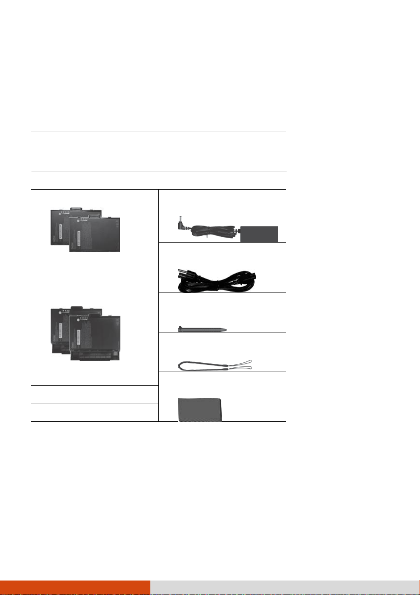
Battery pack x 2
- or High capacity battery
pack x 2
AC adapter
AC power cord
Stylus
Tether
Screen cleaning cloth
Document(s)
Driver disc (optional)
Unpacking
After unpacking the shipping carton, you should find these standard items:
K120 Tablet
Keyboard Dock (optional)
Inspect all the items. If any item is damage or missing, notify your dealer
immediately.
Page 9
3
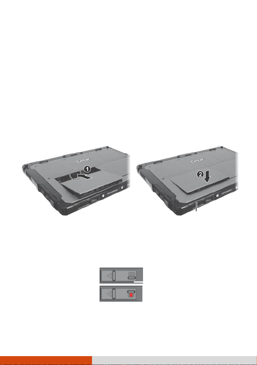
Installing the Battery Packs
Locked
Lock
Unlocked
(revealing red part)
K120 has two battery compartments for two battery packs; each is installed
in the same way.
1.
With the battery pack correctly oriented, attach its connector side to the
battery compartment at an angle ( ) and then press down the other
side ( ). The battery release latch should automatically engage.
NOTE:
different from the one shown here. The removal and installation method is
the same.
If you have the high capacity battery model, the battery pack looks
Battery release
latch
2.
Slide the lock of the battery release latch downward to the locked position.
CAUTION:
underneath red part.
Make sure the latch is correctly locked, not revealing the
Page 10
4
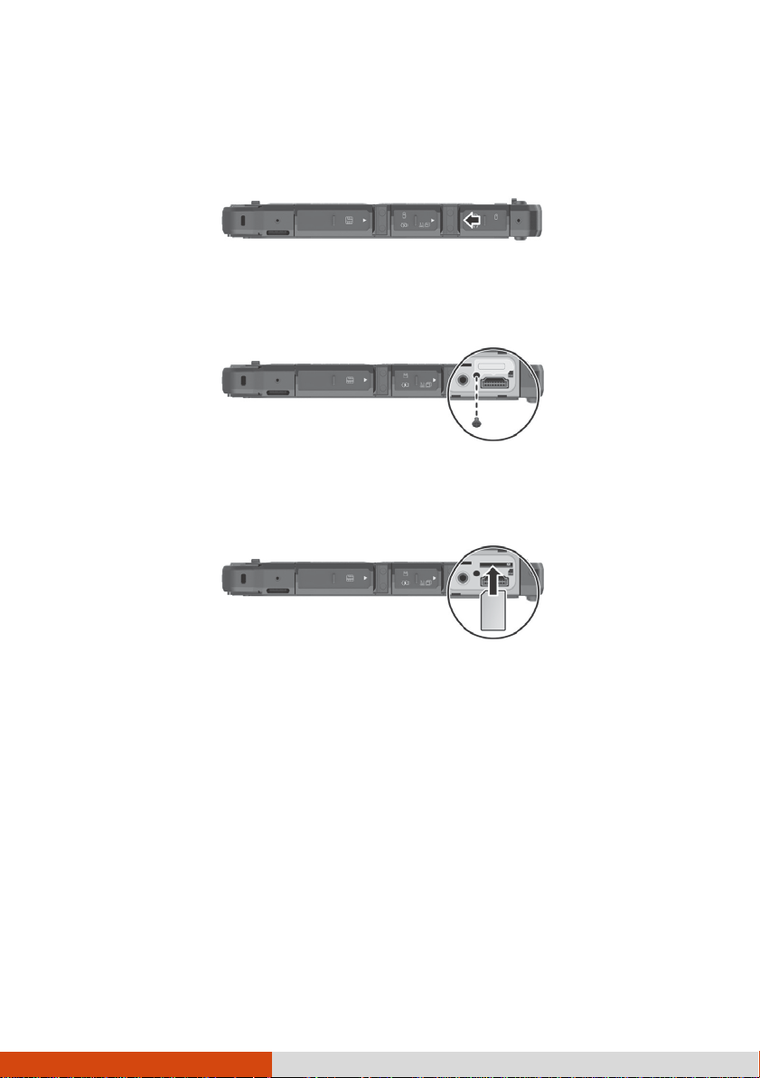
Installing the Micro-SIM Card (Optional)
1.
Locate the micro-SIM card slot. Slide the protective cover to the unlocked
position and open the cover.
2.
Remove one screw to detach the small metal plate that covers the
micro-SIM card slot.
3.
Noting the orientation, insert the micro-SIM card all the way into the
slot.
NOTE:
then pull it out.
To remove the micro-SIM card, just push in the card to release it and
Page 11
5
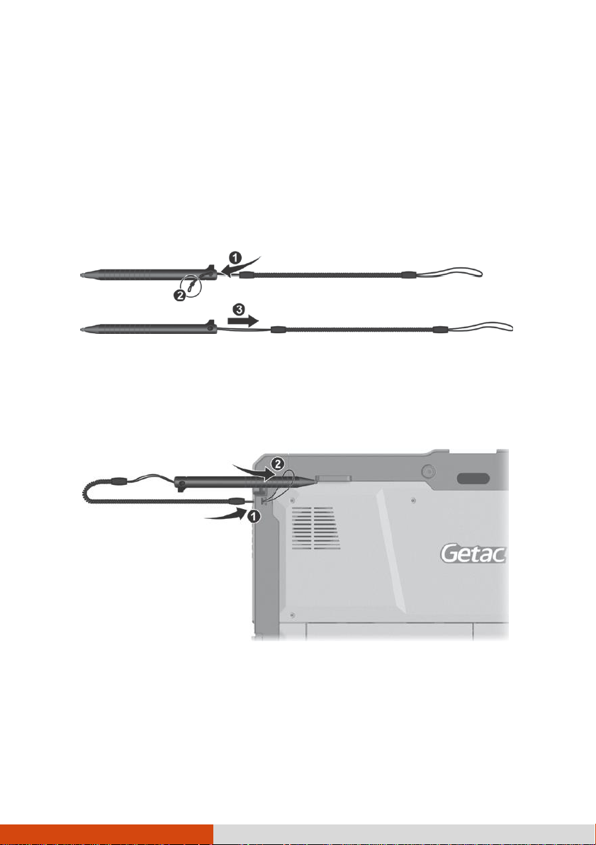
Using the Tether
A tether is provided for attaching the stylus to your Tablet.
1.
Thread one of the tether’s loop through the hole of the stylus ( ), tie a
dead knot at the end ( ), and pull the tether ( ) so that the knot fills in
the hole and prevents the tether from falling off.
2.
Insert the other loop to the tether hole on the Tablet ( ). Then, insert
the stylus through the loop ( ) and pull it tight.
Page 12
6
Connecting to AC Power
CAUTION:
other AC adapters may damage the computer.
Use only the AC adapter included with your computer. Using
NOTE:
The battery pack is shipped to you in power saving mode that protects it
from charging/discharging. It will get out of the mode to be ready for
use when you install the battery pack and connect AC power to the
computer for the very first time.
When the AC adapter is connected, it also charges the battery pack. For
information on using battery power, see Chapter 3.
You must use AC power when starting up the computer for the very first
time.
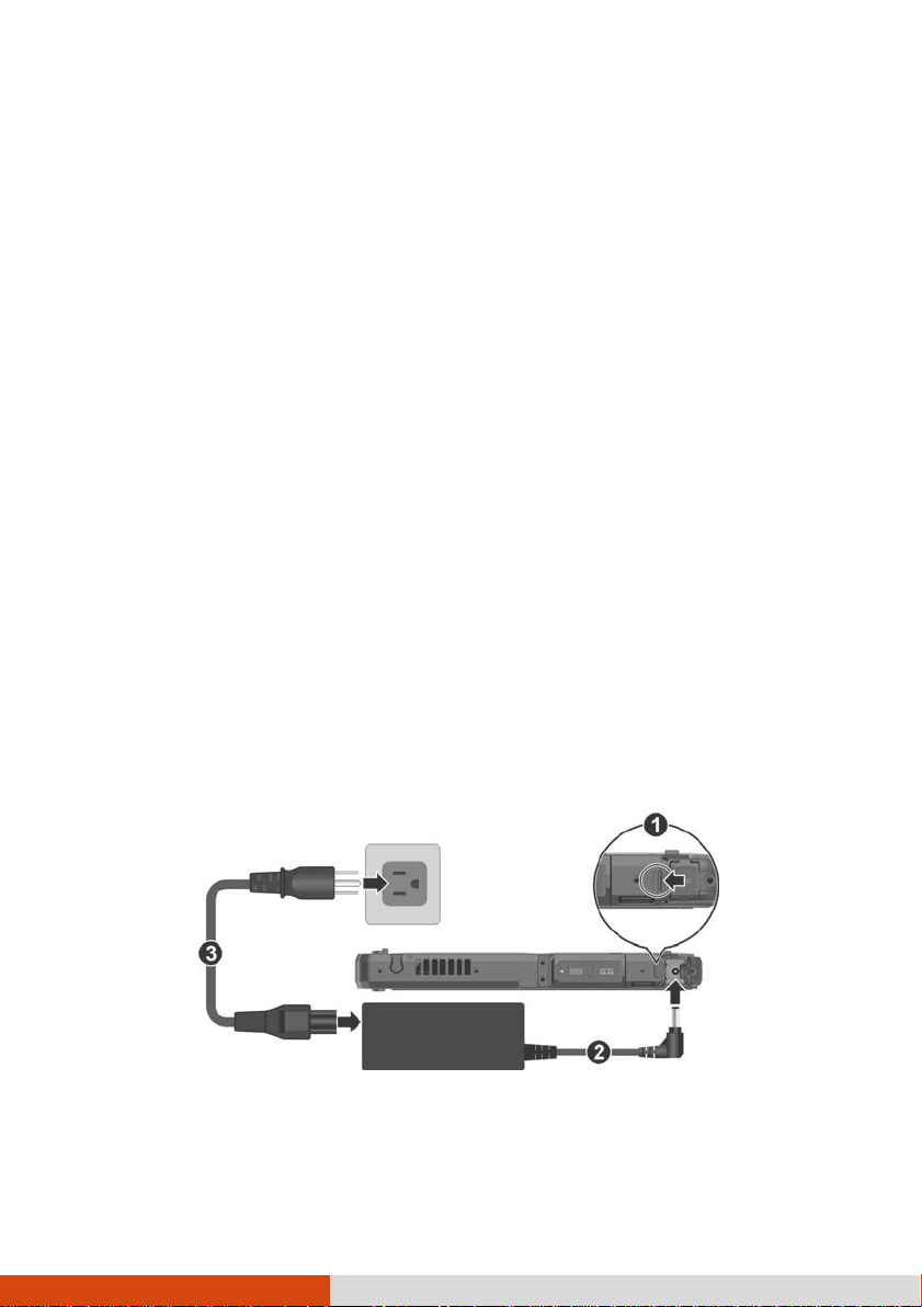
1. Tablet Only:
Open the cover of the power connector. The cover is protected by a
sec
urity lock. Slide the lock outward
Plug the DC c
ord of the AC adapter to the power c
(
) to
unlock the cover.
onnector
(
Plug the female end of the AC power cord to the AC adapter and the
mal
e end to an electrical
outlet
(
).
).
Page 13
7
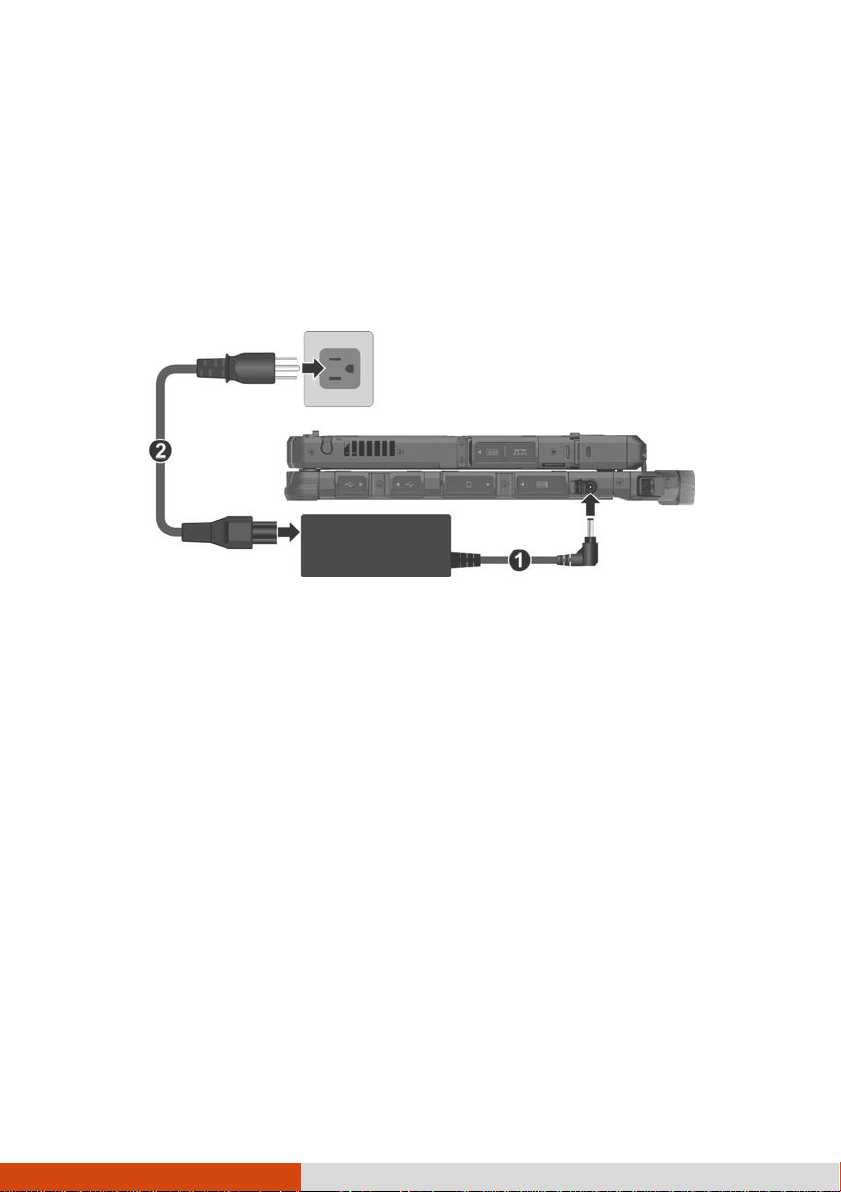
Tablet + Keyboard Dock:
Open the cover of the power connector.
Plug the DC cord of the AC adapter to the power connector ( ).
Plug the female end of the AC power cord to the AC adapter and the
male end to an electrical outlet ( ).
NOTE:
to K120.
2.
See “Attaching the Keyboard Dock” to know how to attach the dock
Power is being supplied from the electrical outlet to the AC adapter and
onto your computer. Now, you are ready to turn on the computer.
Page 14
8
Turning On and Off the Computer
To...
Do this...
Power off
(Shutdown)
Select Power Shut down.
Sleep
Use one of these methods:
Press the power button.*
Select Power Sleep.
With the Keyboard Dock:
Close the top cover.*
Press Fn + F12.*
Hibernate
By default, this option is not shown in the Start menu. If
you want to use the feature, set up accordingly in Windows
settings.
Turning On
Press the power button ( ) for at least 2 seconds until the Power Indicator
lights up. The Windows operating system should start.
NOTE:
By default, there is 2-second delay time for the power button. You can
change the se
tting with
the
“Power Button
Delay” item in the BI
Setup Utility. (See “Advanced Menu in Chapter 5.)
Tapping the screen during startup may invoke a pre-boot menu (unless
the default settings have been changed). If the menu appears, simply
select Continue.
Turning Off
When you finish a working session, you can stop the system by turning off
the power or leaving it in Sleep or Hibernation mode:
OS
*
“Sle
ep” is the default result of
action does through Windows settings.
the action
. You can cha
nge what
the
Page 15
9
Identifying Hardware Components
Ref
Component
Description
NOTE:
computer may not be exactly the same as those shown in this manual.
CAUTION:
When not using a connector, make sure to close the cover completely for
water- and dust-proof integrity. (Engage the locking mechanism if existing.)
Depending on the model you purchased, the appearance of your
You need to open the protective covers to access the connectors.
Tablet Components
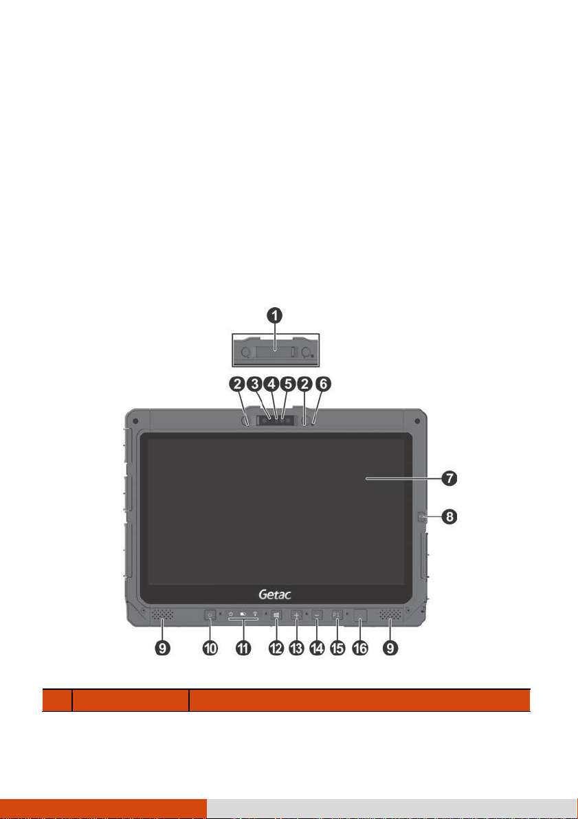
Front Components
Page 16

10
Camera cover
Covers the camera lens.
Slide the cover to open or close it. The cover
provides privacy protection.
Page 17

11
Ref
Component
Description
CAUTION:
When using the internal microphone,
make sure the camera cover is fully closed or
opened. An in-between position can interfere with
the microphone function.
Microphone
Receives sound and voice to record voice.
Camera indicator
Lights up when the camera is in use.
IR sensor
(optional)
Detects the infrared energy of objects to form an
image. The sensor flashes red light when in use.
The near infrared (IR) imaging capability allows you
to use Windows Hello face authentication.
Camera lens
Allows you to use the camera function.
Light sensor
Detects the surrounding lighting condition for
automatic adjustment of the LCD brightness.
Touchscreen
Displays and receives information for the computer.
P2 button
The default function is
Camera
or
Barcode Trigger
depending on your model.
Camera
Starts the G-Camera application.
Barcode
Trigger
Serves as the trigger button for the barcode
reader if your model has the module.
Stereo speaker
Sends out sound and voice from your computer.
Power button
Turns the power on or off. (The default
“off”
state
is
“Sleep mode.”)
With a default setting of 2-second delay, you have
to press the button for at least 2 seconds for it to
function.
Indicators
Power
Lights blue when the power is on.
Blinks blue when the system is in Sleep mode.
Battery
Lights amber when the battery is being charged.
Lights green when battery charging is completed.
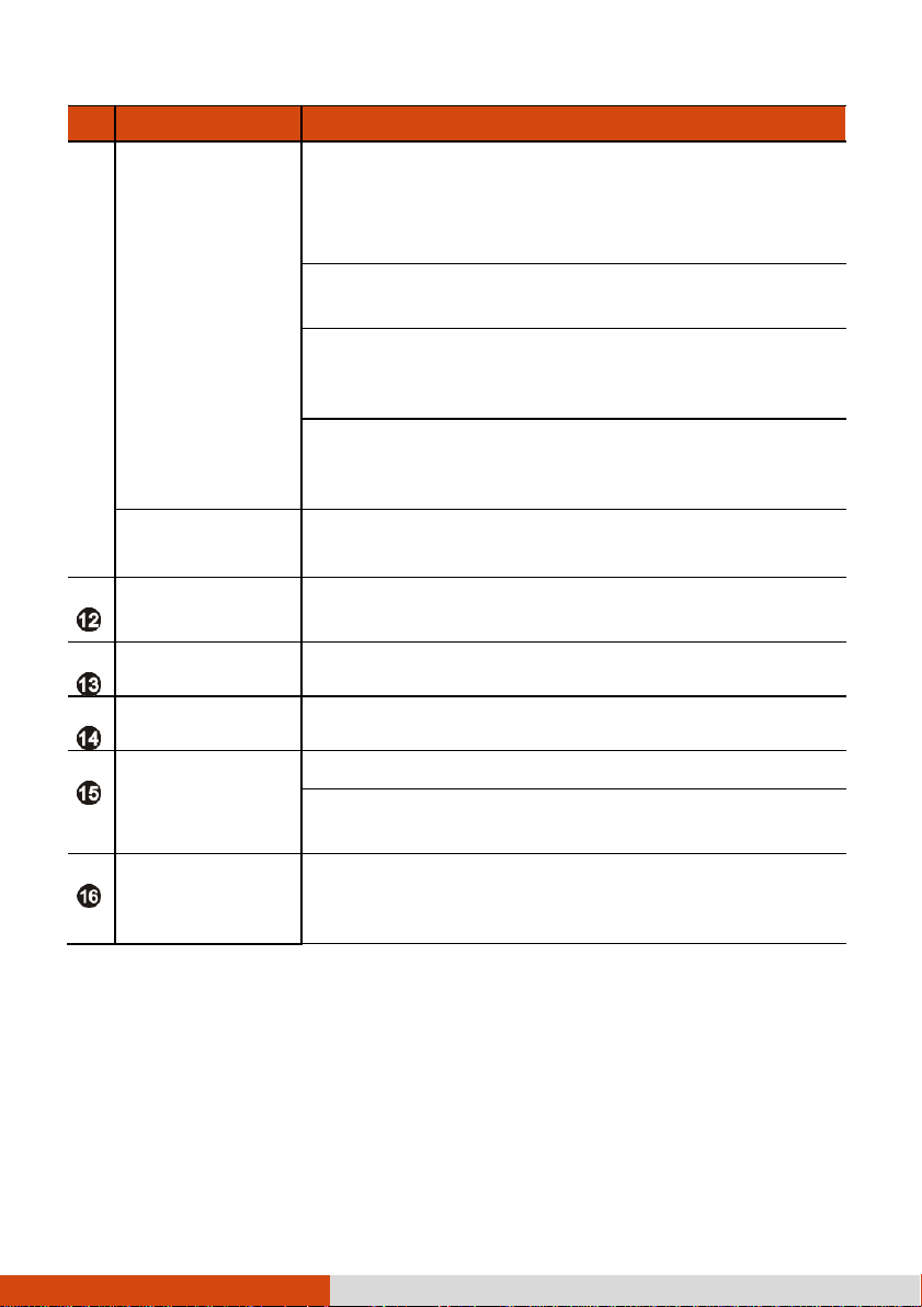
Page 18
12
Ref
Component
Description
Blinks green to indicate the battery’s built-in high
temperature protection mechanism is activated.
CAUTION:
Do not remove the battery during this
period.
Blinks red (once per second) when the battery’s
capacity is below 10%.
Blinks red rapidly (once per 0.5 second) when there
is a thermal protection problem. Ask for repair
service in case this happens.
Blinks amber when the battery charging is in an
abnormal state. Replace the battery in case this
happens.
RF (Radio
Frequency)
Lights blue when the RF radio of any RF feature
(WLAN/Bluetooth/WWAN) is on.
Windows logo
button
Opens or closes the Start menu.
Plus button
Increases the sound volume.
Minus button
Decreases the sound volume.
P1 button
Opens or closes the OSD Control Panel.
When pressed longer:
Serves as the Ctrl+Alt+Del keyboard keys.
Fingerprint
scanner
(optional)
Serves as the fingerprint verification, preventing
unauthorized access to your computer.
NOTE:
using G-Manager.
The hardware buttons (except the power button) can be re-defined
Page 19
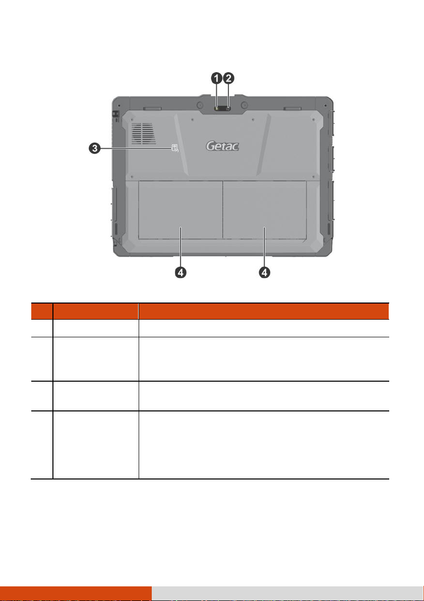
13
Rear Components
Ref
Component
Description
Flash
Provides extra light when taking pictures.
Camera lens
Allows you to use the camera function.
When the camera lens is in use, the indicator beside
it lights up.
NFC/RFID reader
(optional)
Reads data from NFC/RFID tags.
Battery pack
Supplies power to your computer when external
power is not connected.
NOTE:
If you have the high capacity battery model,
the battery pack looks different from the one
shown here.
Page 20
14
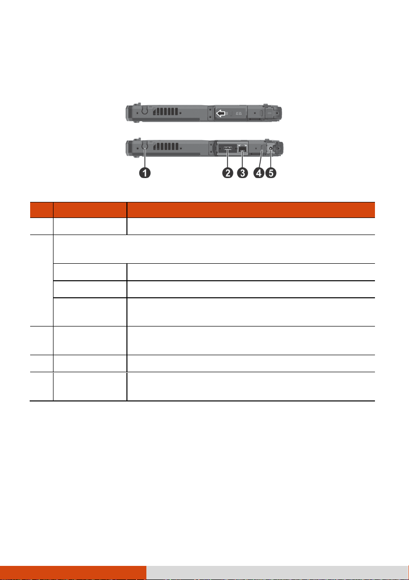
Right-Side Components
Ref
Component
Description
Stylus holder
Holds the stylus.
Depending on the model, the component can be one of the
following:
None
USB 2.0 port
Connects a USB device.
RS232 serial
connector
Connects a serial device.
RJ-45
connector
Connects the LAN cable.
Security lock
Locks the cover of the power connector.
Power
connector
Connects the AC adapter.
For covers with an arrowhead icon, push the cover toward one side to unlock
and the other side to lock. The arrowhead points to the side for unlocking.
Page 21
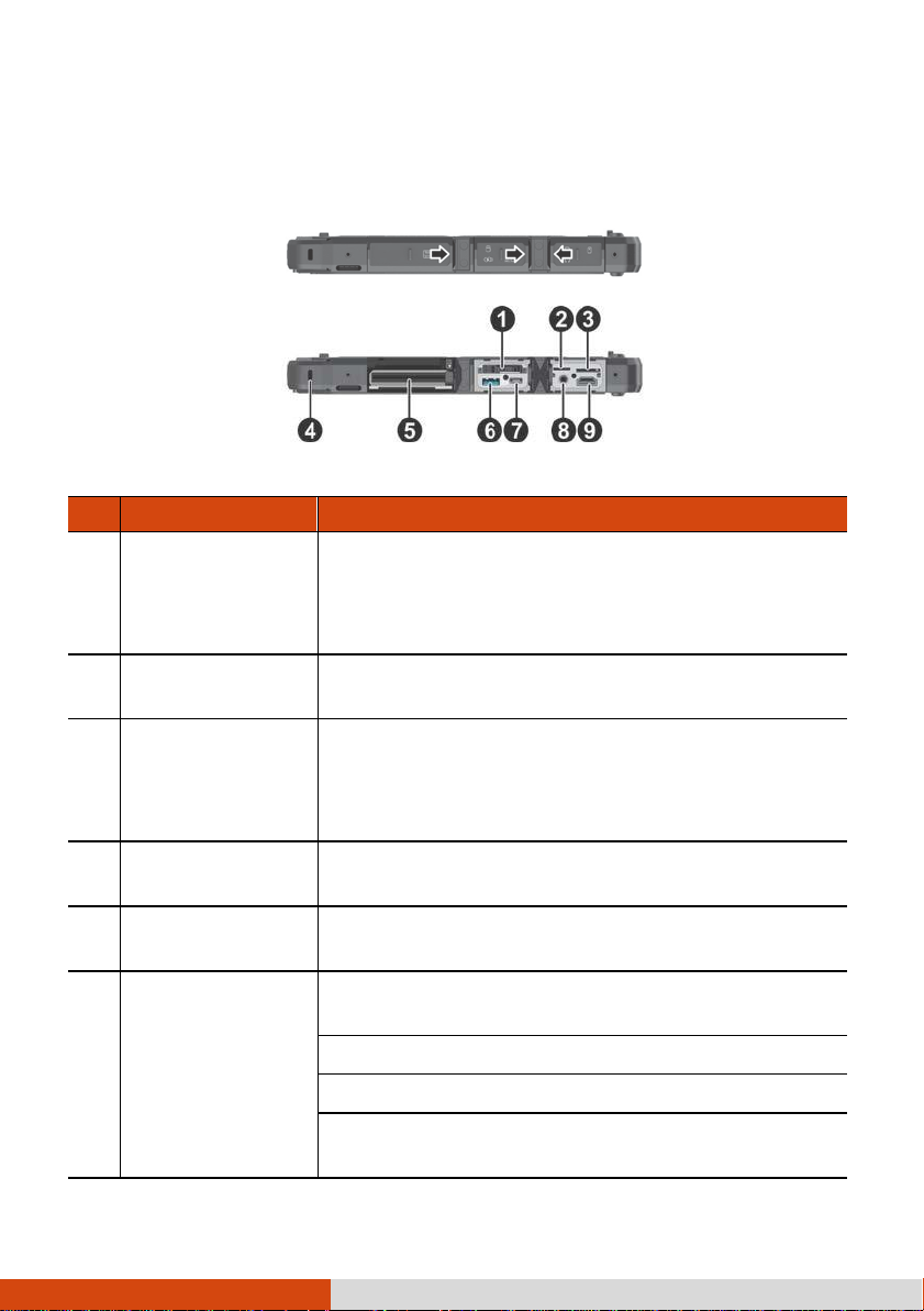
15
Left-Side Components
Ref
Component
Description
SSD canister
Contains the solid-state drive, which is the mass
storage device of your computer.
CAUTION:
This device is not hot-swappable. Do
not remove it without turning off the system first.
MicroSD card slot
Accepts a microSD card for removable storage
media.
Micro-SIM card
slot
(optional)
Accepts a micro-SIM card for models having the
WWAN module.
NOTE:
The slot still exists but cannot be used for
models without the WWAN module.
Kensington lock
Locks the computer to a stationary object for
security.
Smart card
reader
(optional)
Accepts a smart card for additional security
feature.
PowerShare USB
3.0 port
Provides either of the below two functions
depending on your setting.
Charges a connected mobile device.
- or -
Functions as a standard USB 3.0 port (default
setting).
For covers with an arrowhead icon, push the cover toward one side to unlock
and the other side to lock. The arrowhead points to the side for unlocking.
Page 22
16
Ref
Component
Description
USB 3.1 Gen 1
Type-C port
Connects a USB device that supports USB Type-C
connection.
Combo audio
connector
Connects a set of headphones or external
speakers with amplifier.
Supports a headset microphone with 4-pole TRRS
3.5mm jack.
HDMI connector
Connects a HDMI monitor or TV set.
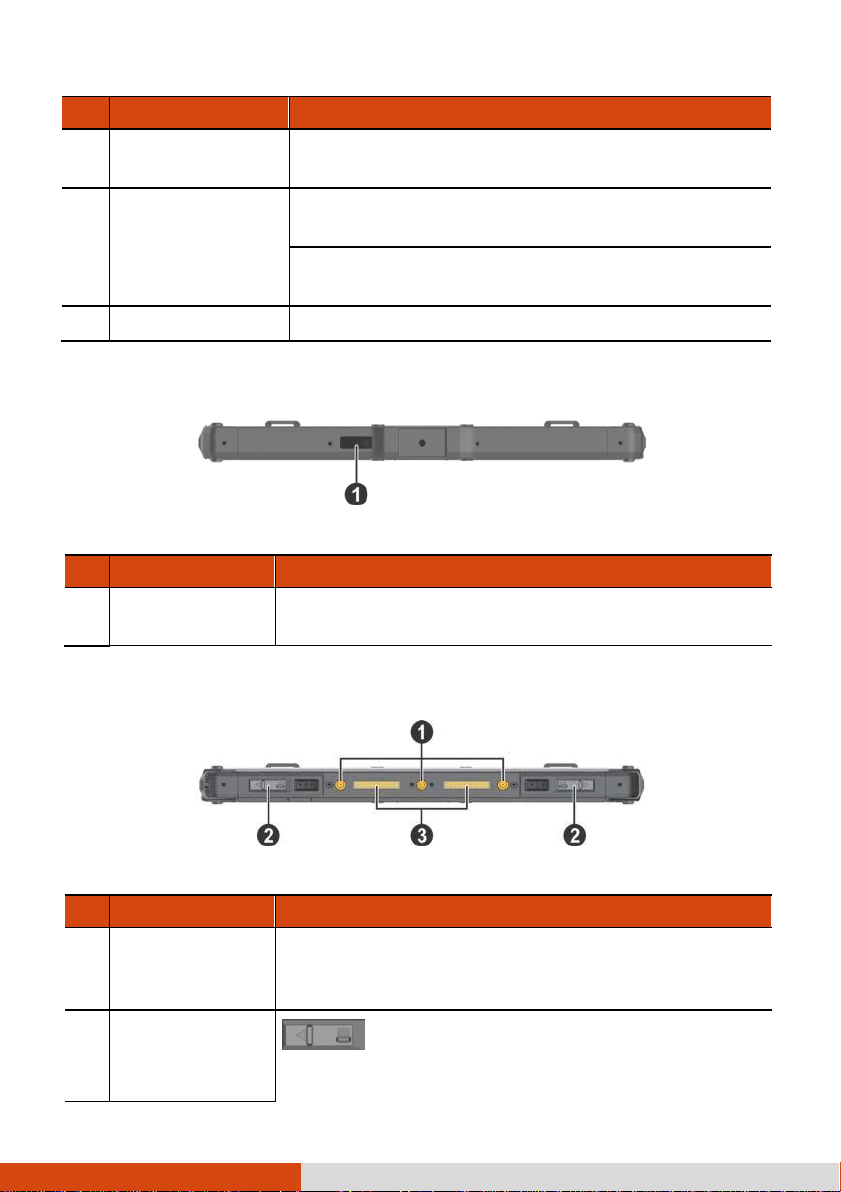
Top Components
Ref
Component
Description
Barcode reader
lens
(optional)
Scans and reads barcodes.
Ref
Component
Description
Tri antenna
passthrough
(optional)
Connects to the docking station for using external
WLAN/GPS/WWAN antenna.
Battery release
latch
Releases the battery pack. The latch has a locking
mechanism.
Locked
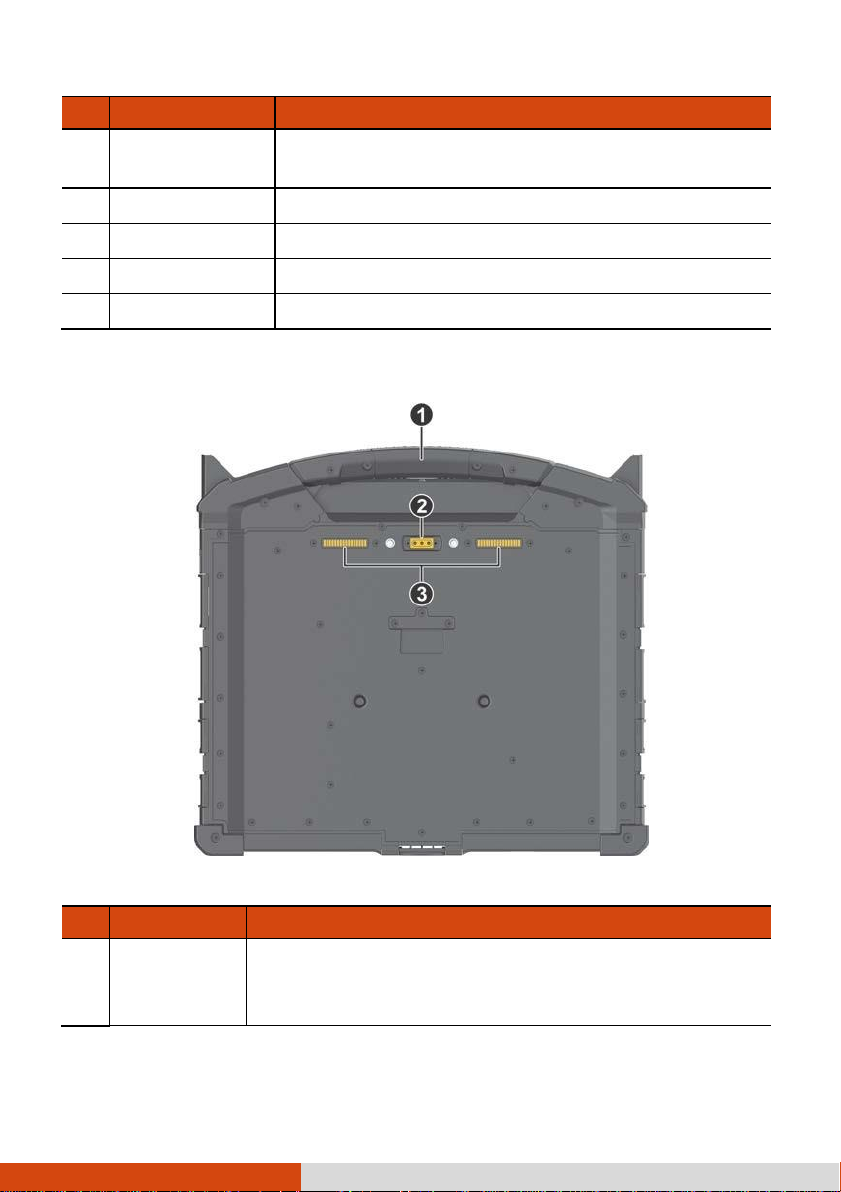
Bottom Components
Page 23

17
Unlocked
Page 24
18
Ref
Component
Description
Docking
connectors
Connect a proprietary dock such as the keyboard
dock, office dock, and vehicle dock.
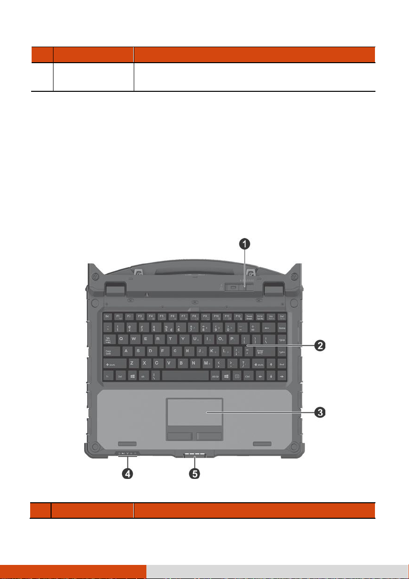
Keyboard Dock Components (Optional)
Ref
Component
Description
NOTE:
The Keyboard Dock can be purchased separately. Specific models come
with the Keyboard Dock.
S
ee “Multiple Usage Mode
Top Components
s” later in this cha
pter for more i
nformati
on.
Page 25

19
Tablet release
latch
Releases the Tablet. The latch has a locking
mechanism.
Page 26
20
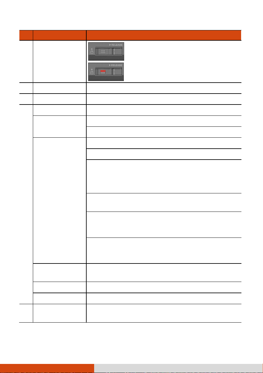
Ref
Component
Description
Locked
Unlocked
Keyboard
Serves as the data input device of the computer.
Touchpad
Serves as the pointing device of the computer.
Indicators
Power
Lights blue when the computer is on.
Blinks blue when the computer is in Sleep mode.
Battery
Lights amber when the battery is being charged.
Lights green when battery charging is completed.
Blinks green to indicate the battery’s built-in high
temperature protection mechanism is activated.
CAUTION:
Do not remove the battery during this
period.
Blinks red (once per second) when the battery’s
capacity is below 10%.
Blinks red rapidly (once per 0.5 second) when there
is a thermal protection problem. Ask for repair
service in case this happens.
Blinks amber when the battery charging is in an
abnormal state. Replace the battery in case this
happens.
RF (Radio
Frequency)
Lights blue when the RF radio of any RF feature
(WLAN/Bluetooth/WWAN) is on.
Caps Lock
Lights blue when Caps Lock is on.
Num Lock
Lights blue when Num Lock is on.
Top cover latch
Locks the Tablet and Keyboard Dock in the closed
position.
Page 27
21
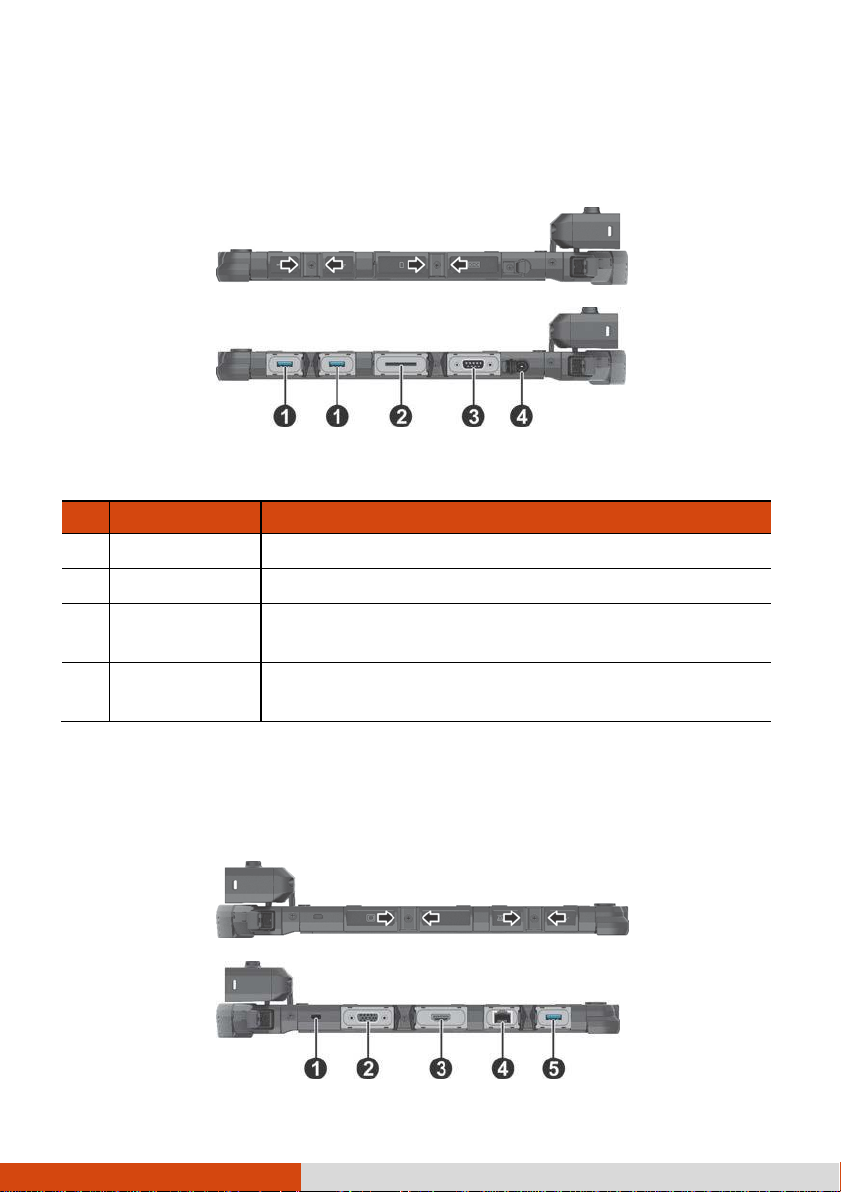
Right-Side Components
Ref
Component
Description
USB 3.0 port
Connects a USB device.
SD card slot
Accepts a SD card for removable storage media.
RS232 serial
connector
Connects a serial device.
Power
connector
Connects the AC adapter.
For covers with an arrowhead icon, push the cover toward one side to unlock
and the other side to lock. The arrowhead points to the side for unlocking.
Left-Side Components
For covers with an arrowhead icon, push the cover toward one side to unlock
and the other side to lock. The arrowhead points to the side for unlocking.
Page 28

22
Page 29
23
Ref
Component
Description
Kensington lock
Locks the Keyboard Dock to a stationary object for
security.
VGA connector
Connects an external display monitor.
HDMI connector
Connects a HDMI monitor or TV set.
RJ-45 connector
Connects the LAN cable.
USB 3.0 port
Connects a USB device.
Bottom Components
Ref
Component
Description
Handle
Provides a convenient way to carry the computer.
The extendable handle also serves as a stabilizer for
the touchscreen to hold firm when you tap on it.
Page 30

24
Ref
Component
Description
Tri antenna
passthrough
(optional)
Connects to the docking station for using external
WLAN/GPS/WWAN antenna.
WLAN WWAN
GPS
Docking
connector
Connects a proprietary dock such as the office dock
and vehicle dock.
Page 31

25
Multiple Usage Modes
Usage Mode
Description
Notebook Mode
When the Tablet and Keyboard Dock are
assembled, the system works as a regular
notebook computer.
Tablet Mode
You can easily detach the Keyboard Dock and
leave it behind when you desire the portability
of the Tablet.
Convertible Mode
You can transform the system from notebook to
tablet and back again.
For the transformation, the Tablet has to be
detached, flipped over, and then reattached.
NOTE:
This mode is not supported if the high
capacity battery packs are installed.
NOTE:
come with the Keyboard Dock.
The Keyboard Dock can be purchased separately. Specific models
With the Keyboard Dock, you can use K120 in different usage modes. (For
i
nformation on
how to change modes, see “Changing Usage M
ode
s” later
.)
Page 32

26
Presentation Mode
When the screen faces outwards, you can use
the Keyboard Dock as a stand for the Tablet.
NOTE:
This mode is not supported if the high
capacity battery packs are installed.
Page 33

27
Changing Usage Modes
Changing usage modes means attaching or detaching the Keyboard Dock.
Attaching the Keyboard Dock
1.
Make sure the cover of the power connector on K120 Tablet is closed and
locked.
2.
Depending on the desired usage mode, have K120 Tablet face inwards or
outwards.
Align and put K120 Tablet down on the holder. The release latch should
click into place.
Notebook Mode
3.
Slide the lock of the release latch upwards to the locked position.
Convertible/Presentation Mode
Page 34

28
Page 35

29
Detaching the Keyboard Dock
1.
Slide the lock of the release latch downwards to the unlocked position.
2.
Push the release latch toward the right, and while holding the latch ( ),
lift K120 Tablet out of the holder ( ).
Page 36

30
Opening and Closing the Display
To open:
1.
2.
Pry open the cover latch ( ).
Lift up the display (i.e. K120 Tablet) (
or backward for optimal viewing clarity.
). You can tilt the cover forward
CAUTION:
(120 degrees).
3.
There is a limit to the tilting angle. Do not go beyond the limit
While using the touchscreen function in Notebook Mode, extend the
handle to stabilize the Keyboard Dock.
Page 37

31
Page 38

32
To close:
1.
Close the display.
2.
Lift the cover latch to engage it on the display.
Page 39

33
Chapter 2
Operating Your
Computer
This chapter provides information about the use of the computer.
If you are new to computers, reading this chapter will help you learn the
operating basics. If you are already a computer user, you may choose to read
only the parts containing information unique to your computer.
CAUTION:
Do not expose your skin to the computer when operating it in a very hot
or cold environment.
The computer can get uncomfortably warm when you use it in high
temperatures. As a safety precaution in such a circumstance, do not place
the computer on your lap or touch it with your bare hands for extended
periods of time. Prolonged body contact can cause discomfort and
potentially a burn.
Page 40

34
Navigating on the Screen
The screen of your computer is touch-sensitive. You can operate the computer
by touching the screen with your finger or the stylus.
CAUTION:
touchscreen. Doing so may damage the touchscreen surface.
NOTE:
Do not use a sharp object such as a ballpoint pen or pencil on the
An optical film has been attached to the screen before shipment. The
film is a consumable, which will be worn out by possible scratches. You can
purchase a new one when replacement is required.
Using the Touchscreen
Your computer has a capacitive touchscreen. This type of touchscreen
responds to objects that have conductive properties, such as fingertips and a
capacitive-tipped stylus.
You can change the touchscreen sensitivity settings to suit your scenario.
Double-tap the
Touch Screen Mode
the settings menu and select one of the options (as shown below).
Select this if you prefer using
fingertips. Also, select this
when raindrops are falling
on the screen and should be
rejected as input.
NOTE:
In high temperatures (above 60 oC / 140 F), set the mode to
of
Glove
If liquid is spilled on the touchscreen causing a wet area, the area will stop
or
Pen
mode.
shortcut on Windows desktop to open
Select this if you are using the
stylus. (You must use the one
supplied with your model.)
Select this if you are wearing gloves
(referring to warm gloves or work gloves,
not referring to touchscreen-capable gloves).
Touch
instead
Page 41

35
responding to any inputs. For the area to function again, you must dry it.
Page 42

36
The following table shows how you use the touchscreen to obtain equivalent
Term/Action
Equivalent
Mouse Function
Tap:
Touch the screen once.
Click/Point
Double-tap:
Touch the screen twice rapidly.
Double-click
Tap and hold:
Tap and hold until a popup menu
appears.
Right-click
Drag:
Hold the stylus (or finger) on the screen and drag
across the screen until reaching your destination.
Drag
Gestures
Actions
( = finger down; = finger up)
Descriptions
Pan
(Scroll)
or
Drag 1 or 2 fingers up or down.
Use panning to see
another part of a page
that has scroll bars.
Zoom
(Pinch)
Move two fingers apart/toward each
other.
Use zooming to make
an item (a photo for
example) on the screen
larger or smaller. The
gesture works in
applications that
support mouse wheel
zooming.
mouse functions.
Using Multi-touch Gestures
You can interact with your computer by placing two fingers on the screen.
The movement of the fingers across the screen creates “gestures,” which
send commands to the computer.
Here are the multi-touch gestures that you can use:
Page 43

37
Gestures
Actions
( = finger down; = finger up)
Descriptions
Rotate
or
Move two fingers in opposing
directions.
-orUse one finger to pivot around
another.
Use rotating to move a
picture or other item
on the screen in a
circular direction
(clockwise or counterclockwise). The gesture
works in applications
that support the
specific gesture.
Press and
Tap
Press on target and tap using a
second finger.
Use press and tap to
access the shortcut
menu.
Twofinger
Tap
Tap two fingers at the same time
(where the target is in the midpoint
between the fingers).
The function is defined
by applications that
support the specific
gesture.
Flicks
Make quick drag gestures in the
desired direction.
Flick left or right to
navigate back and
forward in a browser
and other applications.
The gesture works in
most applications that
support back and
forward.
Page 44

38
Using the Dual Mode Display (Optional)
Dual mode display (if your model has the feature) incorporates both
touchscreen and digitizer functions.
The display is set to Touchscreen mode by default. Touchscreen mode
provides all the functionalities that an ordinary touchscreen has. When the
Computer receives signals from the digitizer pen, the display automatically
switches to Digitizer mode.
You can move the cursor by bringing the digitizer pen close to the screen,
without actually touching the screen’s surface.
Page 45

39
Using the Keyboard Dock
NOTE:
come with the Keyboard Dock.
The Keyboard Dock can be purchased separately. Specific models
Using the Keyboard
Your keyboard has all the standard functions of a full-sized computer
keyboard plus an
The standard functions of the keyboard can be further divided into four
major categories:
Typewriter keys
Cursor-control keys
Numeric keys
Function keys
Typewriter Keys
Fn
key added for specific functions.
Typewriter keys are similar to the keys on a typewriter. Several keys are
added such as the
The Control (
other keys for program-specific functions. The Escape (
for stopping a process. Examples are exiting a program and canceling a
command. The function depends on the program you are using.
Ctrl, Alt, Esc
Ctrl
) / Alternate (
, and lock keys for special purposes.
Alt
) key is normally used in combination with
Esc
) key is usually used
Cursor-Control Keys
Cursor-control keys are generally used for moving and editing purposes.
NOTE:
know exactly where on your screen anything you type will appear. It can
take the form of a vertical or horizontal line, a block, or one of many other
The word “cursor” refers to the indicator on the screen that lets you
Page 46

40
shapes.
Page 47

41
Numeric Keypad
A 15-key numeric keypad is embedded in the typewriter keys as shown next:
Numeric keys facilitate entering of numbers and calculations. When Num
Lock is on, the numeric keys are activated; meaning you can use these keys to
enter numerals.
NOTE:
When the numeric keypad is activated and you need to type the English
letter in the keypad area, you can turn Num Lock off or you can press
and then the letter without turning Num Lock off.
Some software may not be able to use the numeric keypad on the
computer. If so, use the numeric keypad on an external keyboard
instead.
The
Num Lock
key can be disabled. (See “Main Menu” in Chapter 5.)
Fn
Page 48

42
Function Keys
Key
Description
Switches the keyboard backlight on and off (option).
Switches the RF (radio frequency) radio on and off.
When off, all wireless modules (such as WLAN, Bluetooth,
and WWAN) cannot be used. When on, individual settings
of the module work.
Decreases the sound volume.
Increases the sound volume.
On the top row of the keys are the function keys:
F1
to
F12
. Function keys
are multi-purpose keys that perform functions defined by individual
programs.
Fn Key
The
Fn
key, at the lower left corner of the keyboard, is used with another
key to perform the alternative function of a key. To perform a desired
function, first press and hold Fn, then press the other key.
Hot Keys
Hot keys refer to a combination of keys that can be pressed any time to
activate special functions of the computer. Most hot keys operate in a cyclic
way. Each time a hot key combination is pressed, it shifts the corresponding
function to the other or next choice.
You can easily identify the hot keys with the icons imprinted on the keytop.
The hot keys are described next.
Page 49

43
Key
Description
Switches the display output to the next choice if an external
display is connected. Choices are:
LCD only
LCD + External display (Duplicate)
LCD + External display (Extend)
External display only
The hot keys are equivalent to Windows logo key + P.
Decreases the LCD brightness.
Increases the LCD brightness.
Switches the touchscreen on or off.
Switches the touchpad off or on.
Switches the system sound output off (mute) or on.
Switches the display on or off.
Serves as the sleep button that you can define with
Windows’
Power Options.
Windows Keys
The keyboard has two keys that perform Windows-specific functions:
Windows Logo key and Application key.
The Windows Logo key opens the
Start
menu and performs software-
Page 50

44
specific functions when used in combination with other keys. The
Application key usually has the same effect as a right mouse click.
Page 51

45
Using the Touchpad
CAUTION:
may damage the touchpad surface.
Do not use a sharp object such as a pen on the touchpad. Doing so
NOTE:
Press
Fn+F9
to toggle the touchpad on or off.
For optimal performance of the touchpad, keep your fingers and the
pads clean and dry. When tapping on the pad, tap lightly. Do not use
excessive force.
The touchpad is a pointing device that allows you to communicate with the
computer by controlling the location of the pointer on the screen and
making selection with the buttons.
The touchpad consists of a rectangular pad (work surface) and a left and
right buttons. To use the touchpad, place your forefinger or thumb on the
pad. The rectangular pad acts like a miniature duplicate of your display. As
you slide your fingertip across the pad, the pointer (also called cursor) on the
screen moves accordingly. When your finger reaches the edge of the pad,
simply relocate yourself by lifting the finger and placing it on the other side
of the pad.
Here are some common terms that you should know when using the
Page 52

46
touchpad:
Page 53

47
Term
Action
Point
Move your finger on the pad until the cursor points to
the selection on the screen.
Click
Press and release the left button.
–or–
Tap gently anywhere on the pad.
Double-click
Press and release the left button twice in quick
succession.
–or–
Tap twice on the pad rapidly.
Drag and
drop
Press and hold the left button, then move your finger
until you reach your destination (drag). Finally, release
the button (drop) when you finish dragging your
selection to the destination. The object will drop into
the new location.
–or–
Gently tap twice on the pad and on the second tap,
keep your finger in contact with the pad. Then, move
your finger across the pad to drag the selected object to
your destination. When you lift your finger from the
pad, the selected object will drop into place.
Configuring the Touchpad
You may want to configure the touchpad to suit your needs. For example, if
you are a left-handed user, you can swap the two buttons so that you can
use the right button as the left button and vice versa. You can also change
the size of the on-screen pointer, the speed of the pointer, and so on.
To configure the touchpad, go to
Settings
Devices
Mouse & touchpad.
Page 54

48
Using Network and Wireless
Connections
Using the LAN
To connect the network cable to the LAN module, connect one end of the
LAN cable to the RJ-45 connector on the computer and the other end to the
network hub.
If you have the Keyboard Dock:
Page 55

49
Using the WLAN
The WLAN (Wireless Local Area Network) module of your computer supports
IEEE 802.11a/b/g/n/ac.
Turning On/Off the WLAN Radio
To turn on the WLAN radio:
Select
to the
To turn off the WLAN radio:
You can turn off the WLAN radio the same way you turn it on.
If you want to quickly turn off all wireless radio, simply switch on Airplane
mode. You can control the Airplane mode using one of the below methods.
Settings
On
position.
Select
Use the
Press
Airplane Mode
Fn+F1
Network & Internet
Wi-Fi
Settings
(if the Keyboard Dock is connected).
Network & Internet
button in the OSD Control Panel.
. Slide the
Airplane mode
Wi-Fi
switch
.
Connecting to a WLAN Network
1.
Make sure that the WLAN function is enabled (as described above).
2.
Select the network icon in the lower right of the task bar.
3.
Select the device you want to connect from the search results.
4.
Some networks require a network security key or passphrase. To connect
to one of those networks, ask your network administrator or Internet
service provider (ISP) for the security key or passphrase.
For more information on setting a wireless network connection, refer to
Windows online help.
Page 56

50
Using the Bluetooth Feature
The Bluetooth technology allows short-range wireless communications
between devices without requiring a cable connection. Data can be transmitted
through walls, pockets and briefcases as long as two devices are within range.
Turning On/Off the Bluetooth Radio
To turn on the Bluetooth radio:
Select
the
On
Settings
position.
Devices
Bluetooth
. Slide the
Bluetooth
switch to
To turn off the Bluetooth radio:
You can turn off the Bluetooth radio the same way you turn it on.
If you want to quickly turn off all wireless radio, simply switch on Airplane
mode. You can control the Airplane mode using one of the below methods.
Select
Use the
Press
Fn+F1
Settings
Airplane Mode
(if the Keyboard Dock is connected).
Network & Internet
button in the OSD Control Panel.
Airplane mode
.
Connecting to another Bluetooth Device
1.
Make sure that the Bluetooth function is enabled (as described above).
2.
Make sure that the target Bluetooth device is turned on, discoverable and
within close range. (See the documentation that came with the Bluetooth
device.)
3. Select Settings Devices Bluetooth.
4.
Select the device you want to connect from the search results.
5.
Depending on the type of Bluetooth device that you want to connect to,
you will need to enter the pertinent information.
For detailed information on using the Bluetooth feature, see Windows’
online Help
.
Page 57

51
Using the WWAN Feature (Optional)
A WWAN (Wireless Wide Area Network) uses mobile telecommunication
cellular network technologies to transfer data. The WWAN module of your
computer supports 3G and 4G LTE.
NOTE:
Your model only supports data transmission. Voice transmission is not
supported.
For instructions on installing the micro-SIM card, see “Installing the
Micro-SIM Card (Optional)” in Chapter 1.
Activar/desactivar la radio WWAN
To turn on the WWAN radio:
Select
Cellular
To turn off the WWAN radio:
You can turn off the WWAN radio the same way you turn it on.
Settings
Network & Internet
switch to the On position.
Airplane mode
. Slide the
If you want to quickly turn off all wireless radio, simply switch on Airplane
mode. You can control the Airplane mode using one of the below methods.
Select Settings Network & Internet Airplane mode.
Use the
Press
Airplane Mode
Fn+F1
(if the Keyboard Dock is connected).
button in the OSD Control Panel.
Setting up a WWAN Connection
Tap
information on cellular settings in Windows 10, see Microsoft Support
website.)
Settings
Network & Internet
Cellular
. (For detailed
Page 58

52
Chapter 3
Managing Power
Your computer operates either on external AC power or on internal battery
power.
This chapter tells you how you can effectively manage power. To maintain
optimal battery performance, it is important that you use the battery in the
proper way.
Page 59

53
AC Adapter
CAUTION:
The AC adapter is designed for use with your Computer only. Connecting
the AC adapter to another device can damage the adapter.
The AC power cord supplied with your Computer is for use in the country
where you purchased your Computer. If you plan to go overseas with the
Computer, consult your dealer for the appropriate power cord.
When you disconnect the AC adapter, disconnect from the electrical outlet
first and then from the Computer. A reverse procedure may damage the
AC adapter or Computer.
When unplugging the connector, always hold the plug head. Never pull
on the cord.
The AC adapter serves as a converter from AC (Alternating Current) to DC
(Direct Current) power because your Computer runs on DC power, but an
electrical outlet usually provides AC power. It also charges the battery pack
when connected to AC power.
The adapter operates on any voltage in the range of 100~240 V AC.
Page 60

54
Battery Pack
Your computer has two battery packs. The battery pack is the internal power
source for the computer. It is rechargeable using the AC adapter.
NOTE:
“
Care and maintenance information for the battery is provided in the
Battery Pack Guidelines”
section in
Cha
pter 7.
Charging the Battery Pack
NOTE:
Charging will not start if the battery’s temperature is outside the allowed
range, which is between 0 C (32 F) and 50 C (122 F). Once the
temperature meets the requirements, charging automatically resumes.
During charging, do not disconnect the AC adapter before the battery
has been fully charged; otherwise you will get a prematurely charged
battery.
The battery has a high temperature protection mechanism which limits
the maximum charge of the battery to 80% of its total capacity in the
event of high temperature conditions. In such conditions, the battery will
be regarded as fully charged at 80% capacity.
The battery level may automatically lessen due to the self-discharge
process, even when the battery pack is fully charged. This happens no
matter if the battery pack is installed in the computer.
To charge the battery pack, connect the AC adapter to the computer and an
electrical outlet. The Battery Indicator ( ) on the computer glows amber
to indicate that charging is in progress. You are advised to keep the
computer power off while the battery is being charged. When the battery is
fully charged, the Battery Charge Indicator glows green.
The two battery packs are charged in parallel. It takes approximately 5 hours
to fully charge the two battery packs when the power is off and approximately
6 hours when the power is on (may need a longer charging time at lower
temperatures).
CAUTION:
After the computer has been fully recharged, do not immediately
Page 61

55
disconnect and reconnect the AC adapter to charge it again. Doing so may
damage the battery.
Page 62

56
Initializing the Battery Pack
Push-button
You need to initialize a new battery pack before using it for the first time or
when the actual operating time of a battery pack is much less than expected.
Initializing is the process of fully charging, discharging, and then charging. It
can take several hours.
The G-Manager program provides a tool called “Battery Recalibration” for
the purpose. (See “G-Manager” in Chapter 6.)
Checking the Battery Level
NOTE:
operating time can be different from the estimated time, depending on how
you are using the computer.
The operating time of a fully charged battery pack depends on how you are
using the computer. When your applications often access peripherals, you
will experience a shorter operating time.
The two battery packs are discharged in parallel.
Any battery level indication is an estimated result. The actual
By Operating System
You can check the approximate battery level using the battery meter function
of the operating system. To read the battery level in Windows, click the battery
icon on the taskbar.
By Gas Gauge
On the exterior side of the battery pack is a gas gauge for displaying the
estimated battery charge.
Page 63

57
When the battery pack is not installed in the computer and you want to
Battery
Icon
Battery
Level
Description
Discharging
The icon shows the charge remaining in 10-percent
increments until the charge reaches the low-battery
level.
Low
The battery charge has reached the low-battery
level.
Critically
low
The battery charge has reached the critical battery
level. By default, Windows will display a notification
and put your computer into Hibernation.
know the battery charge, you can press the push-button to see the number
of LEDs that light up. Each LED represents 20% charge.
Battery Low Signals and Actions
The battery icon changes appearance to display the current state of the battery.
When the battery is low, the computer’s Battery Indicator ( ) also blinks
red to alert you to take actions.
Always respond to low-battery by connecting the AC adapter, placing your
computer in Hibernation mode, or turning off the computer.
Page 64

58
Replacing the Battery Pack
CAUTION:
There is danger of explosion if the battery is incorrectly replaced. Replace
the battery only with the computer manufacturer’s battery packs.
Discard used batteries according to the dealer’s instructions.
Do not attempt to disassemble the battery pack.
NOTE:
You can hot swap one battery pack while the other one is supplying the
power.
If you have the high capacity battery model, the battery pack looks
different from the one shown here. The removal and installation method
is the same.
To replace the battery pack, follow these steps:
1.
If the Keyboard Dock is connected, detach it. (See “Detaching the
Keyboard Dock” in Chapter 1 for instructions.)
2.
Slide the lock of the battery release latch upwards to the unlocked
position.
3. Slide
the battery rel
ease latch
toward
the left
(
). The battery pack will
slightly pop up. Remove the battery pack from its compartment
(
).
Page 65

59
Page 66

60
4.
Locked
Unlocked
(revealing red part)
Fit another battery pack into place. With the battery pack correctly
oriented, attach its connector side to the battery compartment at an
angle ( ) and then press down the other side ( ). The battery release
latch should automatically engage.
5.
Slide the lock of the battery release latch downward to the locked
position.
CAUTION:
underneath red part.
Make sure the latch is correctly locked, not revealing the
Page 67

61
Power-Saving Tips
Aside from enabling your computer’s power saving mode, you can do your
part to maximize the battery’s operating time by following these
suggestions.
Do not disable Power Management.
Decrease the LCD brightness to the lowest comfortable level.
Shorten the length of time before Windows turn off the display.
When not using a connected device, disconnect it.
Turn off the wireless radio if you are not using the wireless module (such
as WLAN, Bluetooth, or WWAN).
Turn off the computer when you are not using it.
Page 68

62
Chapter 4
Using Options and
Peripherals
This chapter describes the use of optional modules and the connection of
peripherals.
Page 69

63
Using the Fingerprint Scanner
(Optional)
CAUTION:
For optimal performance, both the scanning surface and the finger
should be clean and dry. Clean the scanning surface when needed. You
can use adhesive tape to remove dirt and oil from the scanner surface.
It is not recommended that you use the fingerprint scanner in a below-
freezing temperature. The moisture on your finger can freeze to the
scanner’s metal surface when you touch it, resulting in a failed operation.
Besides, touching freezing metal with your finger can cause frostbite.
The fingerprint scanner (if your model has the feature) provides a strong
authentication mechanism based on fingerprint recognition. You can log on
to Windows and dismiss the lock screen with an enrolled fingerprint instead
of a password.
Fingerprint scanner
Enrolling a Fingerprint
NOTE:
Windows user account.
1. Select Settings Accounts Sign-in options.
2.
3.
You can enroll a fingerprint only after creating a password for the
On the right side under
Follow the onscreen instructions to complete.
Fingerprint
, select
Set up.
Page 70

64
Fingerprint Login
NOTE:
system has to check hardware devices and security configuration before
initiating the fingerprint scanner.
With an enrolled fingerprint, the user can log on by tapping the
option in Windows login screen and then placing the finger on the scanner.
The user can also dismiss the lock screen with the fingerprint.
The fingerprint scanner has 360-degree readability. You can place your finger
in any orientation for the scanner to recognize an enrolled fingerprint.
If fingerprint login attempts fail three times, you will be switched to password
login.
The fingerprint login process can take a while. This is because the
Fingerprint
Page 71

65
Using the Barcode Reader
(Optional)
NOTE:
For enhanced applications and customization of the module, you can use
the Barcode Manager program. (For detailed information on the
program, see the program’s online help.)
The maximum operating temperature for the barcode scanner is 50 C
(122 F).
If your model has the barcode scanner module, you can scan and decode
most common 1D and 2D symbologies.
To read barcodes:
1.
Start your processing software and open a new or existing file. Place the
insertion point (or called cursor) where you want the data to be entered.
2.
Press the Trigger button (P2) on your Tablet. (The button function is
configured by G-Manager.)
3.
The light projected from the lens consists of a center marker and four
corner markers. Make sure the barcode is within the four corner markers.
Adjust the lens’ distance from the barcode, shorter for a smaller barcode
and farther for a larger one.
NOTE:
results.
4.
Improper ambient light and scanning angle can affect the scanning
Upon a successful scan, the system beeps and the decoded barcode data
Page 72

66
is entered.
Page 73

67
Connecting Peripheral Devices
HDMI
VGA
Connecting a Display Monitor
If you want the benefits of a larger display screen with higher resolution,
you can connect an external display monitor to your computer
The Tablet has an HDMI connector.
The Keyboard Dock has a VGA connector and a HDMI connector. Depending
on the type of your monitor, plug the monitor’s signal connector to the
HDMI or VGA connector.
You can switch the display output by using Windows
Control Panel, or
Fn+F5
(if the Keyboard Dock is connected).
Control Panel
, OSD
Page 74

68
Connecting a USB Device
USB 3.0
(depending on
your setting)
USB Type A
The Tablet has one USB 3.0 port and one USB 2.0 port (optional) for
connecting USB devices, such as a digital camera, scanner, printer, modem,
and mouse.
NOTE:
USB port when set up accordingly. (See “Connecting a Device for USB
Charging” later for information.)
The Keyboard Dock has three USB 3.0 ports.
USB 2.0
(Select models
only)
The USB 3.0 port on your Tablet can also function as a PowerShare
Page 75

69
USB 3.1 Gen 1 Type-C
“
USB Type
features small size and free orientation. This port supports:
USB 3.1 Gen 1 (up to 5 Gbps)
DisplayPort over USB-C
CAUTION:
power source to this port.
-C” (or simply “USB-
C”) is
a
physical USB connector f
This port does not support USB Power Delivery. Never connect a
ormat tha
t
NOTE:
to the USB-C connector as long as you have a proper adapter.
You can still connect a USB device that has traditional connector types
Connecting a Device for USB Charging
The Tablet supports a PowerShare USB 3.0 port ( ). You can use this port
to charge mobile devices even when the computer is in power-off, sleep, or
hibernation state.
A connected device is charged by either external power (if the AC adapter is
connected) or by the computer’s battery (if the AC adapter is not connected).
In the latter case, charging will stop when the battery level gets low (20%
capacity).
Notes and Cautions on USB Charging
Page 76

70
To use the USB charging feature, you must first enable the feature by
running the BIOS Setup program or the G-Manager program. (See
“Advanced Menu” in Chapter 5 or “G-Manager” in Chapter 6.)
Otherwise the PowerShare USB port functions as a standard USB port.
Page 77

71
Before connecting a device for charging, make sure the device works
with the USB charging feature.
Connect a device directly to this port. Do not connect via a USB hub.
After resuming from sleep or hibernation, the computer may not detect
the connected device. If this happens, try disconnecting and reconnecting
the cable.
USB charging will stop in the following situations.
– You shut down the computer by pressing the power button for more
than 5 seconds
–
All power (AC adapter and battery pack) is disconnected and then
reconnected during power-off state.
For USB devices which do not require charging, connect them to other
USB ports on your computer.
Connecting a Serial Device
Select models have a serial port for connecting a serial device such as a serial
mouse or serial communication device.
The Keyboard Dock has a serial port.
Select models only
Page 78

72
Page 79

73
Connecting an Audio Device
For higher audio quality, you can send sound through an external audio
device.
The combo connector is the “4-pole TRRS 3.5mm” type (Apple iPhone
Recessed) so you can connect a compatible headset microphone.
SAFETY WARNING:
To prevent possible hearing damage, do not listen at high volume levels for
long periods.
Page 80

74
Using Various Card Readers
Using Storage Cards
The Tablet has a microSD storage card reader. The Keyboard Dock as a SDXC
storage card reader. The storage card reader is a small drive for reading from
and writing to removable storage cards (or called memory cards).
To insert a storage card:
1.
Locate the storage card reader and open the protective cover.
2.
Noting the orientation, slide the card into the slot until it reaches the
end.
3.
Close the cover.
4.
Windows will detect the card and assign it a drive name.
To remove a storage card:
MicroSD
SD/SDXC
1. Open File Explorer and select Computer.
2.
Right-click the drive with the card and select
3.
Slightly push the card to release and then pull it out of the slot.
4.
Close the cover.
Eject.
Page 81

75
Using Smart Cards (Optional)
With an embedded microcontroller, smart cards have the unique ability to
store large amounts of data, carry out their own on-card functions (e.g.,
encryption and mutual authentication), and interact intelligently with a
smart card reader.
To insert a smart card:
1.
Locate the smart card reader and open the protective cover.
2.
Slide the smart card, with its label and embedded computer chip facing
down into the slot.
3.
Close the cover.
To remove a smart card:
1.
Make sure that the software is not accessing the smart card.
2.
Open the cover.
3.
Slightly push the card to release and then pull it out of the slot.
4.
Close the cover.
Page 82

76
Using the NFC/RFID Reader (Optional)
RFID antenna
If your model has the NFC/RFID reader module, you can read data from NFC
(Near Field Communication) and RFID (Radio Frequency Identification) tags.
For optimal results when reading an NFC/RFID tag, have the tag face the
antenna in the same orientation as indicated by the icon on the exterior of
the computer.
NOTE:
When not using an NFC/RFID card, do not leave it within or near the
antenna area.
For enhanced applications and customization of the module, contact
your authorized Getac dealer.
The NFC reader requires specialized applications. For further information,
ask your system administrator.
Page 83

77
Changing or Replacing
Replacing the SSD
1.
Turn off the computer and disconnect the AC adapter.
2.
Locate the SSD canister and open its protective cover.
3.
Pry the rubber strip ( ) to release it ( ).
4.
Using the rubber strip, pull the SSD canister out of the slot.
5.
Noting the orientation, insert the new SSD canister all the way into the
slot.
6.
Make sure the rubber strip is engaged.
Page 84

78
Chapter 5
Using BIOS Setup
BIOS Setup Utility is a program for configuring the BIOS (Basic Input/ Output
System) settings of the computer. BIOS is a layer of software, called
firmware, that translates instructions from other layers of software into
instructions that the computer hardware can understand. The BIOS settings
are needed by your computer to identify the types of installed devices and
establish special features.
This chapter tells you how to use the BIOS Setup Utility.
Page 85

79
When and How to Use
NOTE:
The actual setting items on your model may differ from those described
in this chapter.
The availability of some setting items depends on the configuration of
your computer.
You need to run BIOS Setup Utility when:
You see an error message on the screen requesting you to run BIOS
Setup Utility.
You want to restore the factory default BIOS settings.
You want to modify some specific settings according to the hardware.
You want to modify specific settings to optimize the system performance.
To run BIOS Setup Utility:
Method 1:
During system startup when the logo screen appears, tap the
screen or press the
menu that appears, select
Windows Logo
Setup Utility.
button on your computer. In the pre-boot
NOTE:
If you don’t want any accidental tapping to invoke the pre -boot menu,
you can disable this method by se
Options
” item in the BIOS Setup Utility.
tting
the
“Screen Tapping
for Boot
For Windows 10 models, the time period in which you can use the above
method is extremely short. You can use the other method as described
below.
Method 2: Select Settings Update & security Recovery. Under
Advanced startup, select Restart now. In the boot options menu, select
Troubleshoot Advanced options UEFI Firmware Settings. Select Restart.
Page 86

80
In the pre-boot menu that appears, select Setup Utility.
Page 87

81
Menu Descriptions
Information Menu
The Information menu contains the basic configuration information of the
system. There are no user-definable items in this menu.
NOTE:
asset number for this computer using the asset management program. The
program is provided in the
Main Menu
The Main menu contains the various system settings.
The “Asset Tag” information appears when you have entered the
System Date
System Time
Boot Priority
Select Legacy First or UEFI First according to your needs.
Legacy USB Support enables or disables the system’s support for Legacy
USB.
sets the system date.
sets the system time.
determines the first device that the system boots from.
Asset tag
folder of the Driver disc.
CSM Support
You can set this item to Yes for backward compatibility with legacy BIOS
services.
PXE Boot sets the PXE boot to UEFI or Legacy. PXE (Preboot eXecution
Environment) is an environment to boot computers using a network
interface independently of data storage devices or installed operating
systems.
Internal Numlock
work. When set to Enabled, you can press
enables or disables CSM (Compatibility Support Mode).
sets if the Num Lock function of the keyboard can
Fn + Num Lock
to activate the
Page 88

82
numeric keypad, which is embedded in the typewriter keys. When set to
Disabled, Num Lock does not work. In this case, you can still press
letter key to enter a number.
Fn +
a
Page 89

83
Advanced Menu
The Advanced menu contains the advanced settings.
Wake Up Capability
Any-key Wake Up From S3 state
from S3 (Sleep) state.
allows any key to wake up the system
USB Wake-Up From S3 allows a USB device activity to wake up the
system from S3 (Sleep) state.
Power Button Delay
sets power button delay time (1 second or 2 seconds)
so that accidental touching of the power button does not cause undesired
operation. You can also disable the delay.
System Policy
allows you to choose between Performance and Balance. If
battery life is your first priority, select Balance. If you need system
performance more than battery life, select Performance.
AC Initiation
resume the system.
Screen Tapping for Boot Options
sets if connecting AC power will automatically start or
sets if tapping the screen during
startup will invoke the boot options menu which provides access to some
pre-boot operations. If disabled, tapping the screen during startup has
no effect to the system’s booting process.
USB Power-off Charging (PowerShare USB) enables or disables the USB
charging feature of the PowerShare USB port. When disabled, the
PowerShare USB port functions as a standard USB port. For detailed
information on the PowerShare USB port, see “Connecting a Device for
USB Charging” in Chapter 4.
MAC Address Pass Through allows the system specific MAC address to
pass through a connected dock, meaning the dock specific MAC address
will be overridden by the system specific MAC address. This feature only
works for UEFI PXE boot.
Active Management Technology Support
(This item appears only on
Page 90

84
models supporting vPro.)
Intel AMT Support
enables or disables Intel® Active Management
Technology BIOS extension execution. AMT allows the system
administrator to access an AMT featured computer remotely.
Intel AMT Setup Prompt
Intel AMT Setup appears or not during POST.
determines whether the prompt for entering
Page 91

85
Virtualization Technology Setup
Intel(R) Virtualization Technology
enables or disables Intel® VT (Intel
Virtualization Technology) feature which provides hardware support for
processor virtualization. When enabled, a VMM (Virtual Machine Monitor)
can utilize the additional hardware virtualization capabilities provided by
this technology.
Intel(R) VT for Directed I/O (VT-d)
enables or disables VT-d (Intel®
Virtualization Technology for Directed I/O). When enabled, VT-d helps
enhance Intel platforms for efficient virtualization of I/O devices.
SW Guard Extensions (SGX)
can be set to Disabled, Enabled, or Software
Controlled. Intel® Software Guard Extensions (Intel® SGX) is an Intel
technology for increasing the security of application code. It is used by
application developers.
Graphics Setup
DVMT Pre-Allocated
memory for use by the internal graphics device.
sets the amount of pre-allocated (fixed) graphics
Device Configuration enables or disables several hardware components.
The items available for setting depend on your model.
Diagnostics and System Tester
H2ODST Tool performs system baseline check.
Recovery Partition
allows you to restore your Windows 10 system to the
factory default state by using the “recovery partition” feature. Recovery
partition is a portion of your hard disk drive that is set aside by the
manufacturer to hold the original image of your system.
WARNING:
Using this feature will reinstall Windows to your system and configure it
to the system’s factory default settings. All data on the hard disk drive
will be lost.
Make sure that power is not interrupted during the recovery process. An
unsuccessful recovery may result in Windows startup problems.
Windows RE launches Windows Recovery Environment. Windows RE
Page 92

86
(Windows Recovery Environment) is a recovery environment that
provides recovery, repair, and troubleshooting tools in Windows 10.
Page 93

87
Security Menu
The Security menu contains the security settings, which safeguard your
system against unauthorized use.
NOTE:
You can set the user password only when the supervisor password has
been set.
If both the supervisor and user passwords are set, you can enter any of
them for starting up the system and/or entering BIOS Setup. However,
the user password only allows you to view/change the settings of certain
items.
A password setting is applied right after it is confirmed. To cancel a
password, leave the password empty by pressing the
Set Supervisor/User Password sets the supervisor/user password. You can
set the supervisor/user password to be required for starting up the
system and/or entering BIOS Setup.
Enter
key.
Strong Password
enables or disables strong password. When enabled,
the password you set must contain at least one upper-case letter, one
lower-case letter, and one digit.
Password Configuration
number in the input field and select
between 4 and 64.
Password on Boot
allows you to enable or disable the entering of
password for booting up your system.
sets the minimum password length. Enter the
[Yes]
. The number should be
Secure Boot Configuration (This item appears only when the password
has been set.)
Secure Boot
enables or disables Secure Boot. Secure Boot is a feature
that helps prevent unauthorized firmware, operating systems, or UEFI
drivers from running at boot time.
Delete all Security Boot keys
deletes all secure boot variables.
Page 94

88
Restore Factory Defaults
defaults.
resets secure boot variables to manufacturing
Set HDD 0 User Password
sets the password for locking the Primary
Master hard disk drive. After setting a password, the hard disk drive can
only be unlocked by the password no matter where it is installed.
Page 95

89
Sec
urity Freeze Loc
k enables or disables
the
“Sec
urity Freeze Loc
k”
function. This function is only applicable to SATA drives in AHCI mode. It
prevents attacks on the SATA drive by freezing the security state of the
drive at POST and also when the system resumes from S3.
TPM Setup Menu
TPM Support
TPM (Trusted Platform Module) is a component on your computer’s
enables or disables TPM (Trusted Platform Module) support.
mainboard that is specifically designed to enhance platform security by
providing a protected space for key operations and other security critical
tasks.
Change TPM Status
allows you to select between No Change and Clear.
Intel Trusted Execution Technology
enables utilization of additional
hardware capabilities provided by Intel® Trusted Execution Technology.
Boot Menu
The Boot menu sets the sequence of the devices to be searched for the
operating system.
Boot Type Order
determines the boot order. You can rearrange the
order by dragging the boot device name up or down in the list.
Each boot device can be individually set to On or Off. If you want to
exclude a boot device from the boot order, set the device to Off.
Exit Menu
The Exit menu displays ways of exiting BIOS Setup Utility. After finishing
with your settings, you must save and exit so that the changes can take
effect.
Exit Saving Changes saves the changes you have made and exits BIOS
Setup Utility.
Exit Discarding Changes
changes you have made.
exits BIOS Setup Utility without saving the
Page 96

90
Load Setup Defaults
Discard Changes
loads the factory default values for all the items.
restores the previous values for all the items.
Saves Changes saves the changes you have made.
Page 97

91
Chapter 6
Using Getac Software
Getac software includes application programs for specific computer
components and utility programs for overall management.
This chapter briefly introduces the programs.
Page 98

92
OSD Control Panel
The OSD (On Screen Display) Control Panel provides a user-friendly interface
for you to quickly activate or operate certain functions on your computer
with a simple click of the screen.
To open the OSD Control Panel, start the program named
following screen appears.
OSDC
Help
. The
For detailed information on the program, see the program’s online help.
Page 99

93
G-Manager
G-Manager is a unified user interface utility that allows you to view,
manage, or configure your computer features.
With G-Manager, you can perform all or some of the tasks listed below.
View system information.
Check the battery status and configure the battery.
Configure ECO modes (or called power profiles).
Set the touchscreen sensitivity mode.
Enable PowerShare USB feature.
Set if a warning message will appear when a connected docking station
is removed unexpectedly.
Enable the use of external GPS/WWAN/WLAN antenna signal.
Change the function of the hardware button.
Configure how your system works with the vehicle ignition.
Monitor the system.
View GPS information.
Right-click the Getac Utility icon located on Windows taskbar and select
G-Manager
containing several tabs.
to start the program. The G-Manager window appears,
Page 100

94
NOTE:
appearing on the screen may differ from those shown in this manual.
Depending on your model, the actual items and information
 Loading...