

Page 1

E100
USER’S MANUAL
Rugged Mobile Computing Solutions
Page 2

Jan. 2010
TRADEMARKS
All brand and product names are trademarks or registered trademarks of
their respective companies.
NOTE
The information in this manual is subject to change without notice.
For the latest version of the manual, please visit the Getac website at
www.getac.com
.
Page 3

Table of Contents
Chapter 1 Getting Started..............................................................................................................1-1
Getting the Tablet PC Running .............................................1-2
Unpacking ............................................................................1-2
Connecting to AC Power ..................................................1-3
Using the Hand Strap ..........................................................1-6
Turning On and Off the Tablet PC ....................................1-7
Taking a Look at the Tablet PC .............................................1-8
Front Components ..............................................................1-8
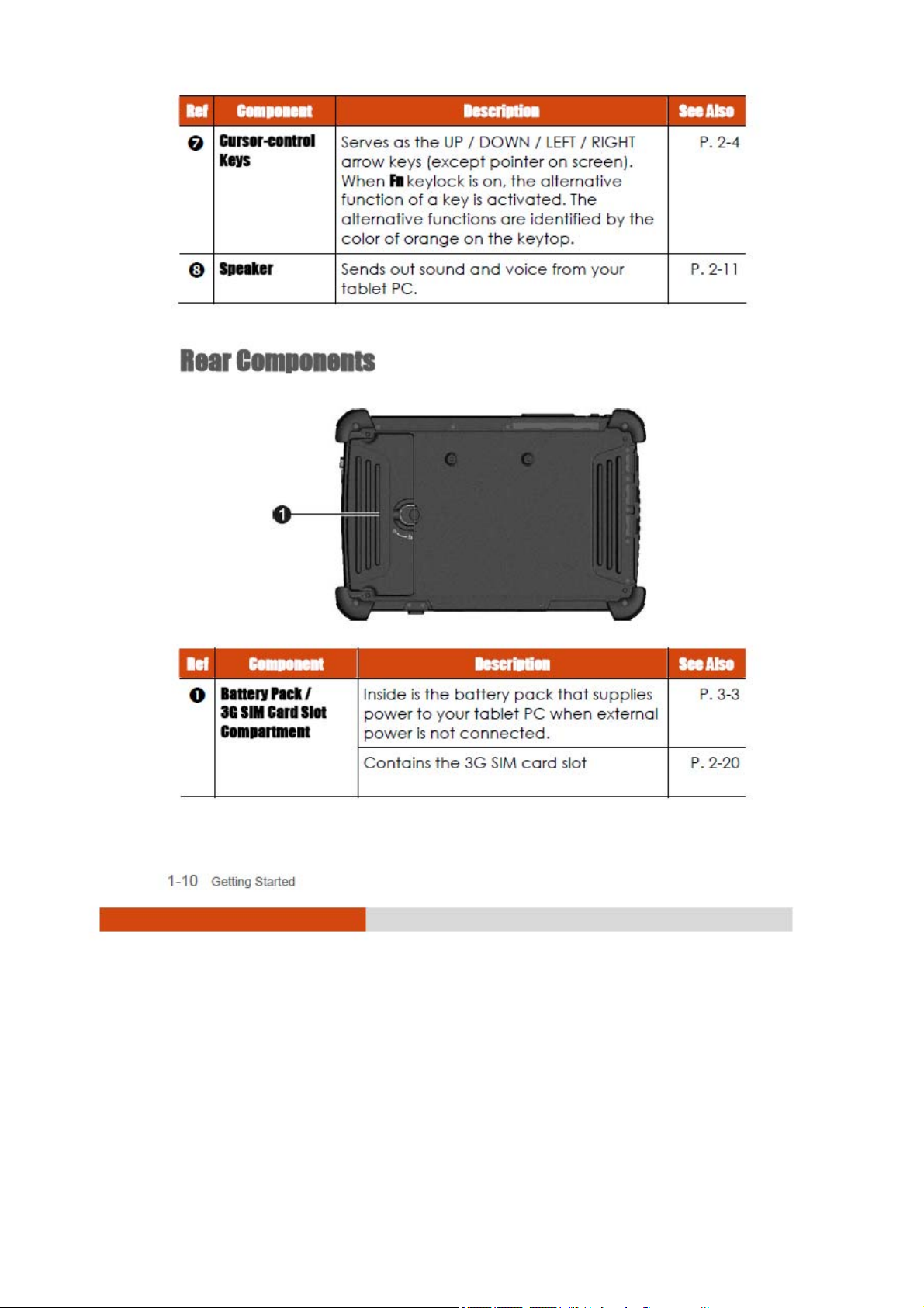
Rear Components.............................................................1-10
Right-Side Components ...................................................1-11
Left-Side Components......................................................1-11
Top Components ..............................................................1-12
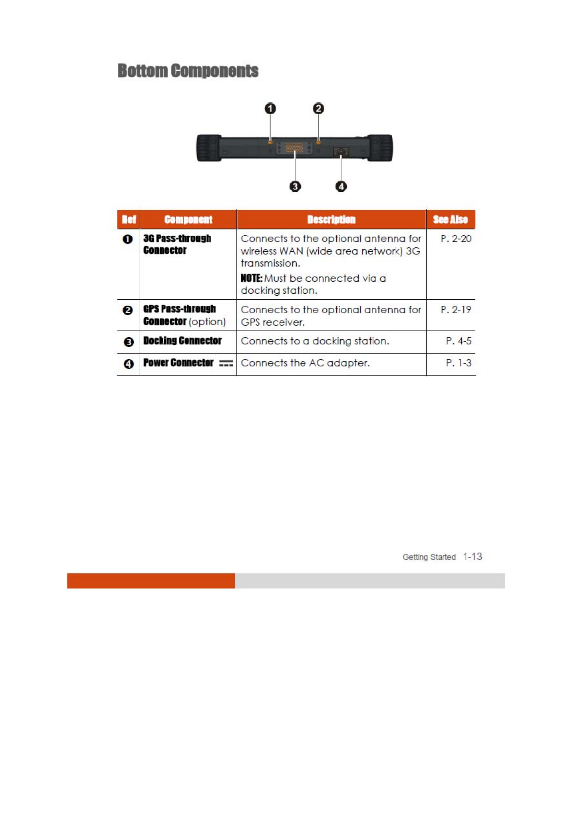
Bottom Components........................................................1-13
Chapter 2 Operating Your Tablet PC.........................................................................................2-1
Starting and Stopping the Tablet PC ...................................2-2
Starting the Tablet PC......................................................... 2-2
Stopping the Tablet PC ......................................................2-2
Using the Keypad ....................................................................2-4
Numeric Keypad with Secondary Functions ..................2-4
Cursor-Control Keys with Secondary Functions..............2-5
Using the On-screen Keyboard .............................................2-6
Using the Touchscreen Pen.................................................... 2-7
Using the Quick Buttons ..........................................................2-9
Using the Video Features......................................................2-10
Configuring the Display Modes ...................................... 2-10
i
Page 4
Page 5

Boot Menu ............................................................................5-8
Exit Menu ..............................................................................5-9
System Recovery ...................................................................5-10
Chapter 6 Using Special Utilities .............................................................................................. 6-1
Using TPM (Trusted Platform Module) ...................................6-2
Using the OSD Control Panel .................................................6-3
Quick Button Setup Utility...................................................6-7
Using the G-Manager Utility .................................................6-10
Starting G-Manager..........................................................6-10
System Tab .........................................................................6-11
Battery Tab .........................................................................6-12
Light Sensor Tab.................................................................6-15
ECO Tab.............................................................................. 6-16
Ignition Tab.........................................................................6-18
Monitoring Tab...................................................................6-19
Antenna Tab ......................................................................6-21
GPS Status Tab...................................................................6-22
Chapter 7 Caring for the Tablet PC ............................................................................................7-1
Protecting the Tablet PC ........................................................7-2
Using the Cable Lock .........................................................7-2
Taking Care of the Tablet PC ................................................7-3
Location Guidelines ............................................................ 7-3
General Guidelines .............................................................7-3
Cleaning Guidelines ...........................................................7-4
Battery Pack Guidelines.....................................................7-4
Touchscreen Guidelines.....................................................7-5
When Traveling ........................................................................ 7-7
Chapter 8 Troubleshooting..........................................................................................................8-1
Preliminary Checklist ...............................................................8-2
Solving Common Problems....................................................8-3
Battery Problems .................................................................8-3
iii
Page 6

Bluetooth Wireless Transmission Problems ....................... 8-3
Display Problems .................................................................8-4
Hardware Device Problems ..............................................8-4
Hard Disk Drive Problems ...................................................8-5
LAN Problems....................................................................... 8-5
Wireless LAN Problems ........................................................8-5
Power Management Problems.........................................8-7
Software Problems ..............................................................8-8
Sound Problems...................................................................8-8
Startup Problems .................................................................8-9
Other Problems....................................................................8-9
Resetting the Tablet PC ........................................................8-11
Appendix A Specifications......................................................................................................................A-1
Appendix B Regulatory Information...................................................................................................B-1
On the Use of the System .......................................................B-2
Class B Regulations .............................................................B-2
Safety Notices......................................................................B-3
On the Use of the RF Device.................................................. B-6
USA and Canada Safety Requirements and Notices ...B-6
European Union CE Marking and Compliance NoticesB-9
iv
Page 7

Chapter 1
Getting Started
Congratulations on purchasing this rugged tablet PC.
This chapter first tells you step by step how to get the tablet PC up and
running. Then, you will find a section briefly introducing the external
components of the tablet PC.
Getting Started 1-1
Page 8

Getting the Tablet PC Running
This section guides you through the procedures for getting the tablet PC
ready for operation.
Unpacking
After unpacking the shipping carton, you should find these standard
items:
z Notebook tablet PC
z Accessories:
− AC adapter
− AC power cord
− Hand strap
− Screen protector film (already attached to the screen)
− Touchscreen pen
Inspect all the items. If any item is damaged or missing, notify your dealer
immediately.
Keep the shipping carton and packing materials in case you need to ship
or store the tablet PC in the future.
1-2
Getting Started
Page 9
Connecting to AC Power
The tablet PC operates either on the external AC power or internal battery
power. It is suggested that you use AC power when you start up the tablet
PC for the very first time.
CAUTION: Use only the AC adapter included with your tablet PC. Using other AC
adapters may damage the tablet PC.
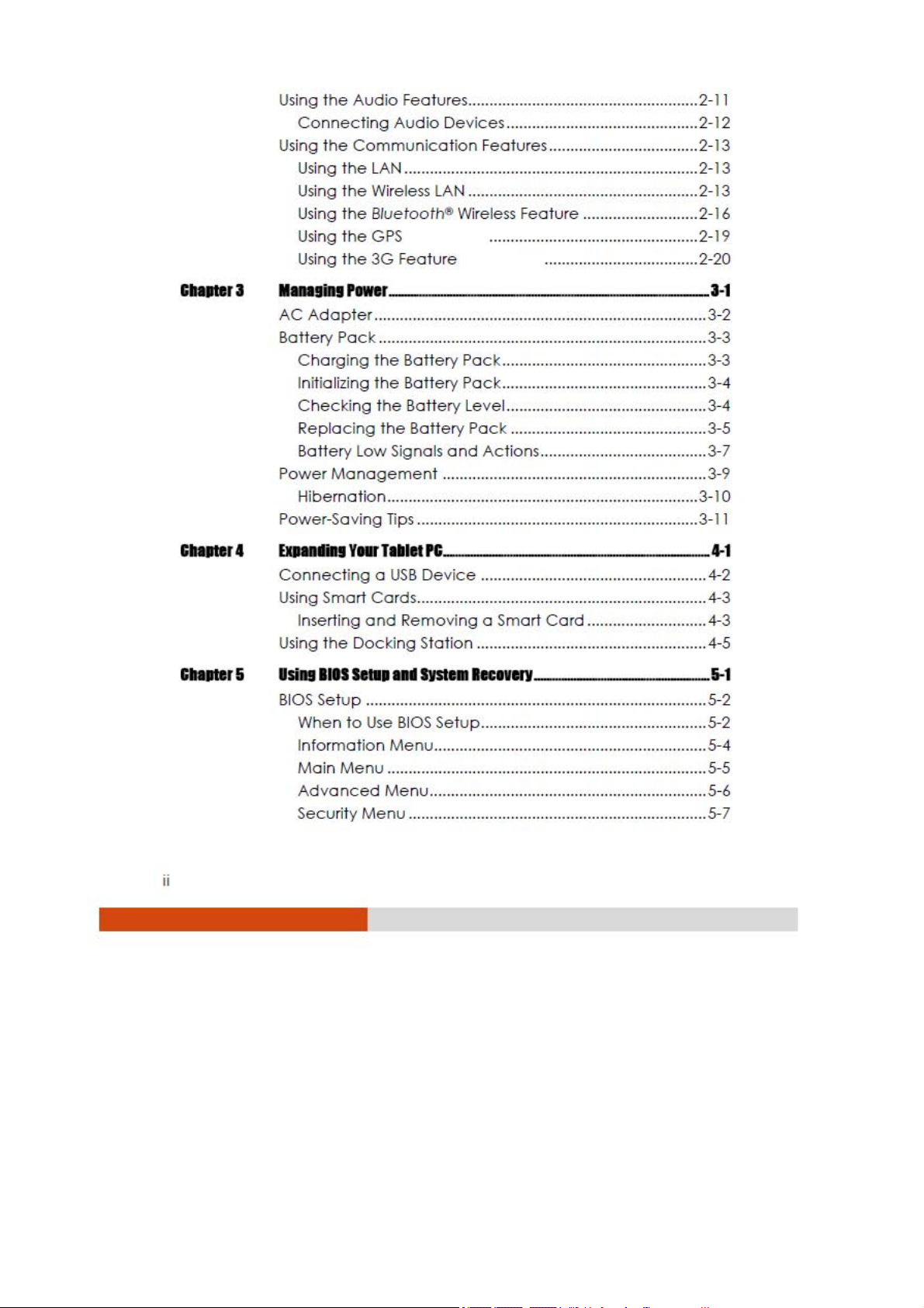
1. Make sure that the tablet PC is turned off.
2. Place the tablet PC upside down.
3. Lift the latch handle of the battery cover and turn it counterclockwise
to the unlock position. Then, detach the cover from the tablet PC.
Unlock
position
Getting Started 1-3
Page 10
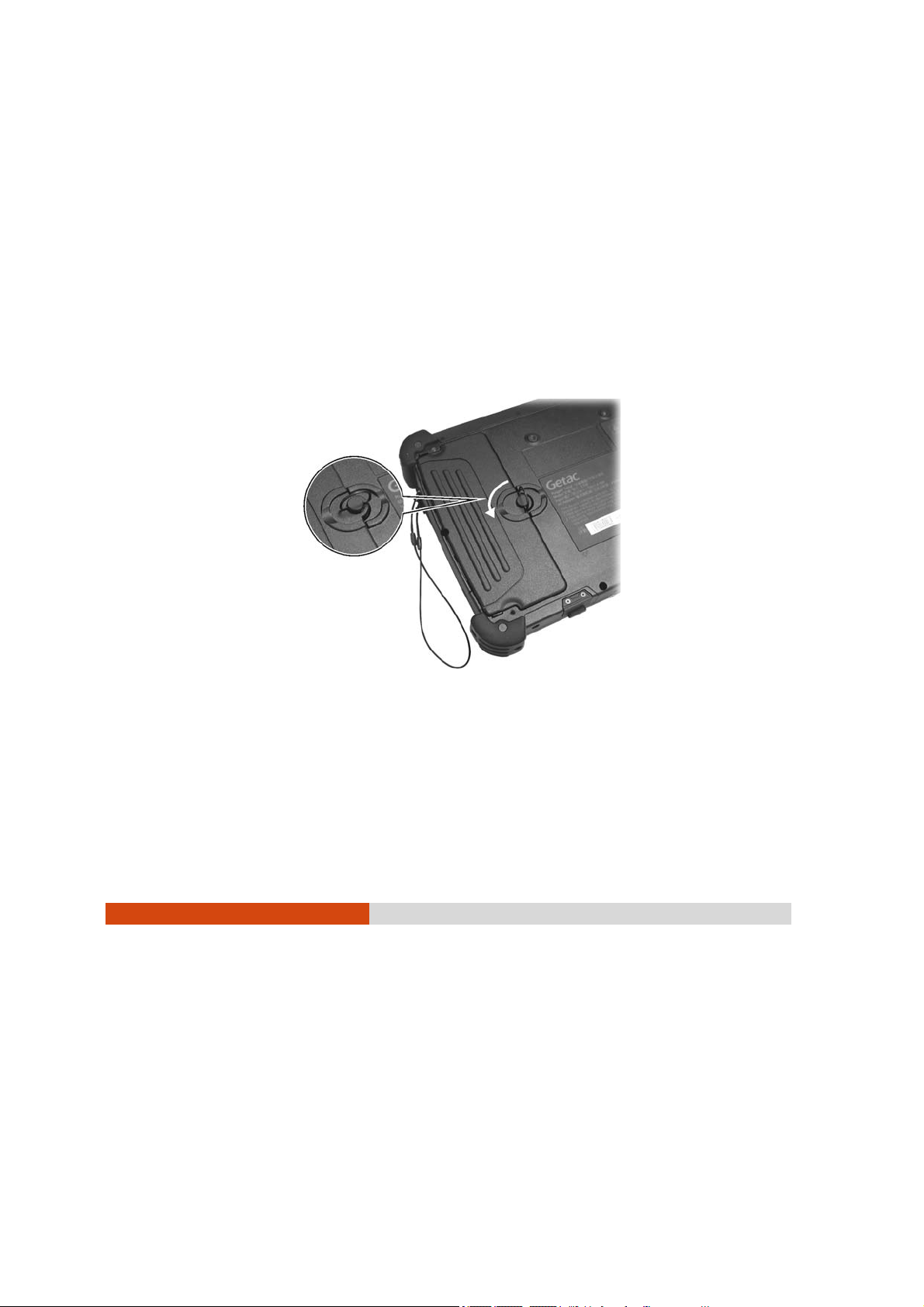
4. Fit the battery pack into place (n). Tightening the two screws (o) is
optional. The lack of the screws will not affect the rugged and
waterproof feature of the tablet PC.
5. Replace the battery cover and turn the latch clockwise to the lock
position.
Lock
position
1-4
Getting Started
Page 11
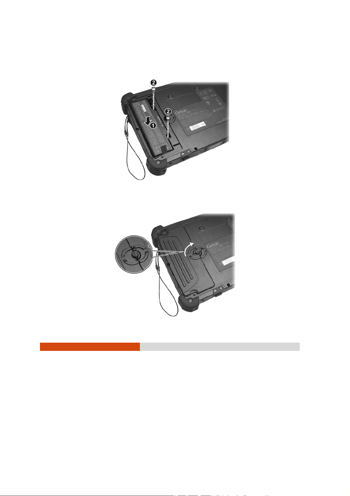
6. Plug the DC cord of the AC adapter to the power connector ( ) of
the tablet PC (n). Plug the female end of the AC power cord to the
AC adapter and the male end to an electrical outlet (o).
7. Power is being supplied from the electrical outlet to the AC adapter
and onto your tablet PC. Now, you are ready to turn on the tablet PC.
8. When the AC adapter is connected, it also charges the battery pack.
The Battery Charge Indicator (
) on the tablet PC glows amber to
indicate that charging is in progress. When the battery is fully charged,
the Battery Charge Indicator glows green. (For information on using
battery power, see Chapter 3.)
CAUTION:
z When you disconnect the AC adapter, disconnect from the electrical outlet
first and then from the tablet PC. A reverse procedure may damage the AC
adapter or the tablet PC.
z When unplugging the connector, always hold the plug head. Never pull on the
cord.
Getting Started 1-5
Page 12
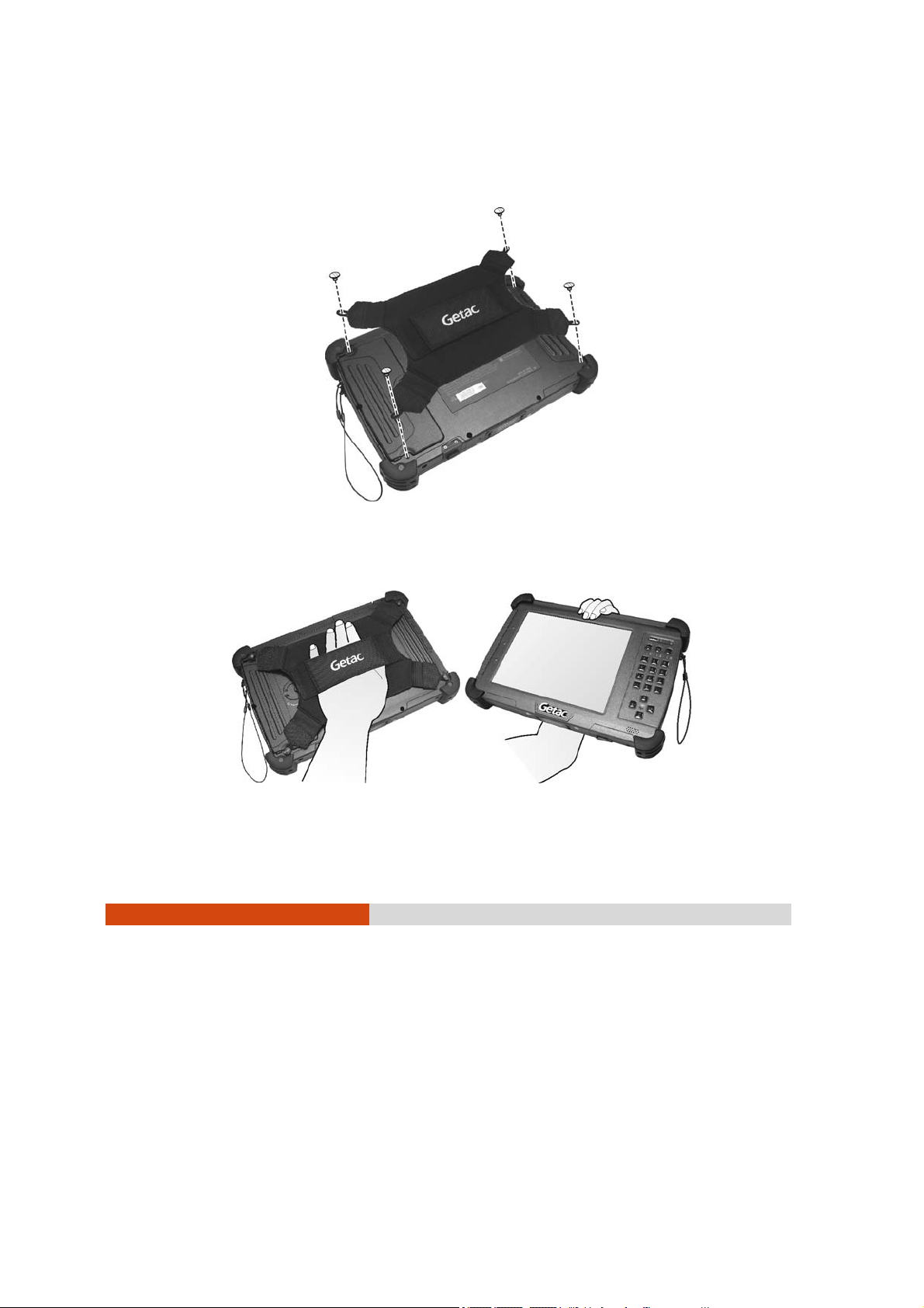
Using the Hand Strap
Align the four hooks of the hand strap with the four corresponding holes
on the tablet PC and tighten the screws.
The hand strap allows you to firmly hold the tablet PC by inserting your
hand through the hand strap.
1-6
Getting Started
Page 13
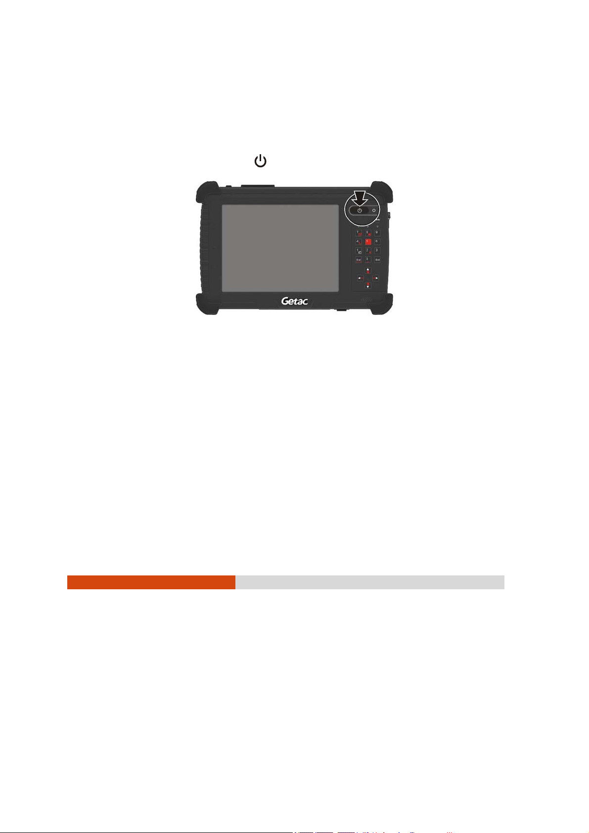
Turning On and Off the Tablet PC
Turning On
1. Make sure that the tablet PC is connected to AC power or the battery
has power.
2. Press the power button (
3. Each time the tablet PC is turned on, it performs a Power-On Self Test
(POST), and the operating system Windows XP Tablet PC edition should
start (may support Windows Vista Business and Ultimate in the future).
).
Turning Off
To turn off the tablet PC power, use the “Shut Down” command of your
operating system.
NOTE: There are other ways you can stop the tablet PC so that you will be back to
where you left off when you next turn on the tablet PC. (See “Stopping the Tablet
PC” in Chapter 2 for information.)
CAUTION: If you have to turn the tablet PC on again immediately after turning it
off, wait for at least five seconds. Turning the tablet PC off and on rapidly can
damage it.
Getting Started 1-7
Page 14
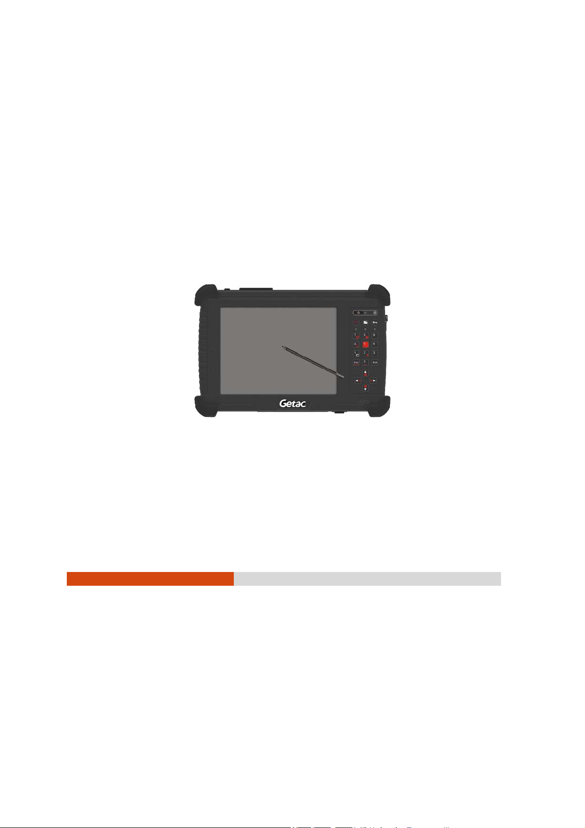
Taking a Look at the Tablet PC
NOTE: Depending on the model you purchased, the appearance of your tablet
PC may not be exactly the same as those shown in this manual.
CAUTION: When not using a connector, make sure that the connector cover is
completely closed to ensure the waterproof integrity of the tablet PC.
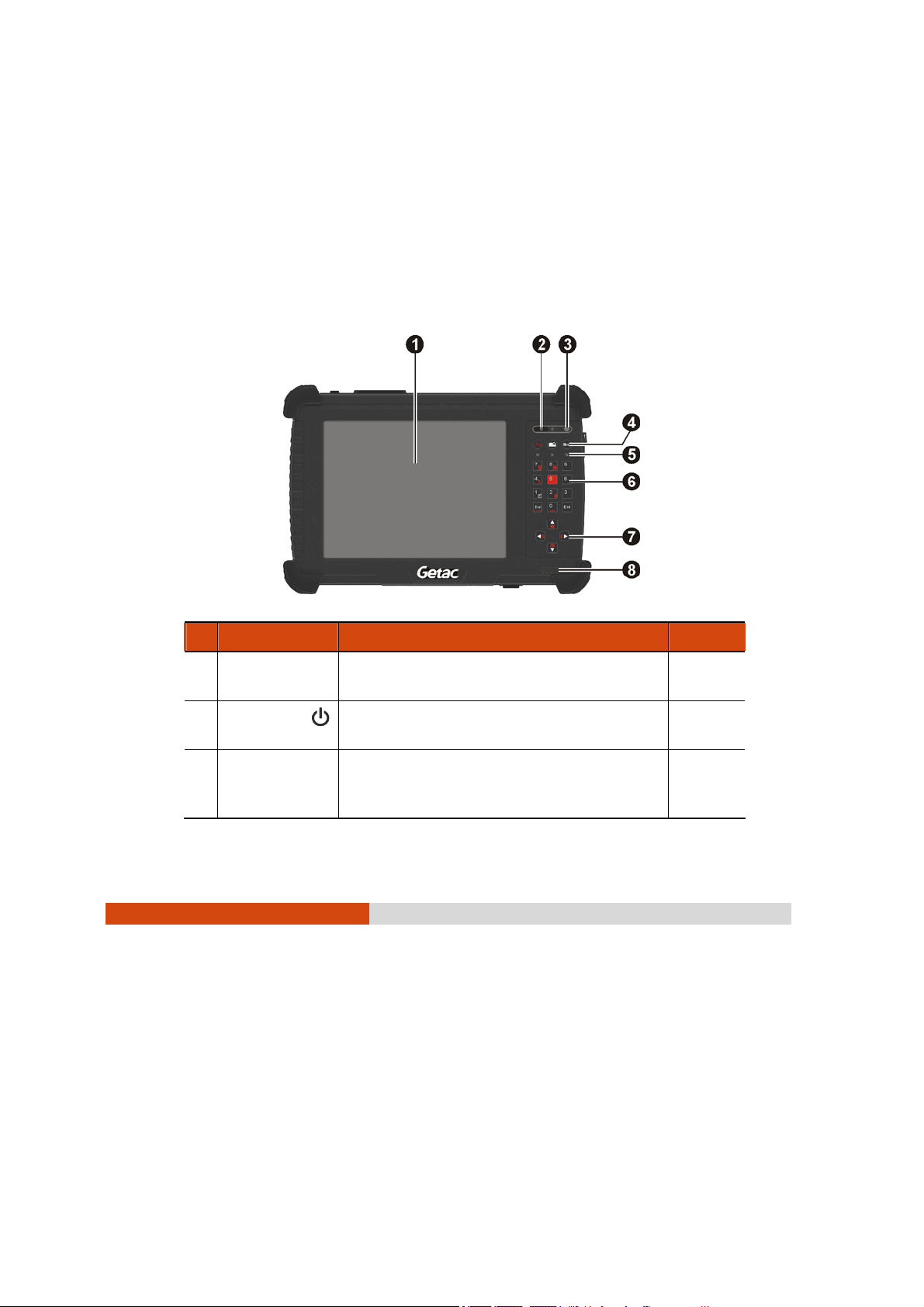
Front Components
Ref Component Description See Also
n
o
p
1-8
Touchscreen
Power Button
Light Sensor
Getting Started
Displays and receives information for the
tablet PC.
Turns the tablet PC power ON and OFF.
The LED lights green when tablet PC is on.
Adjusts the LCD brightness automatically
based on your tablet PC’s surrounding
lighting condition.
P. 2-7
P. 1-7
Page 15
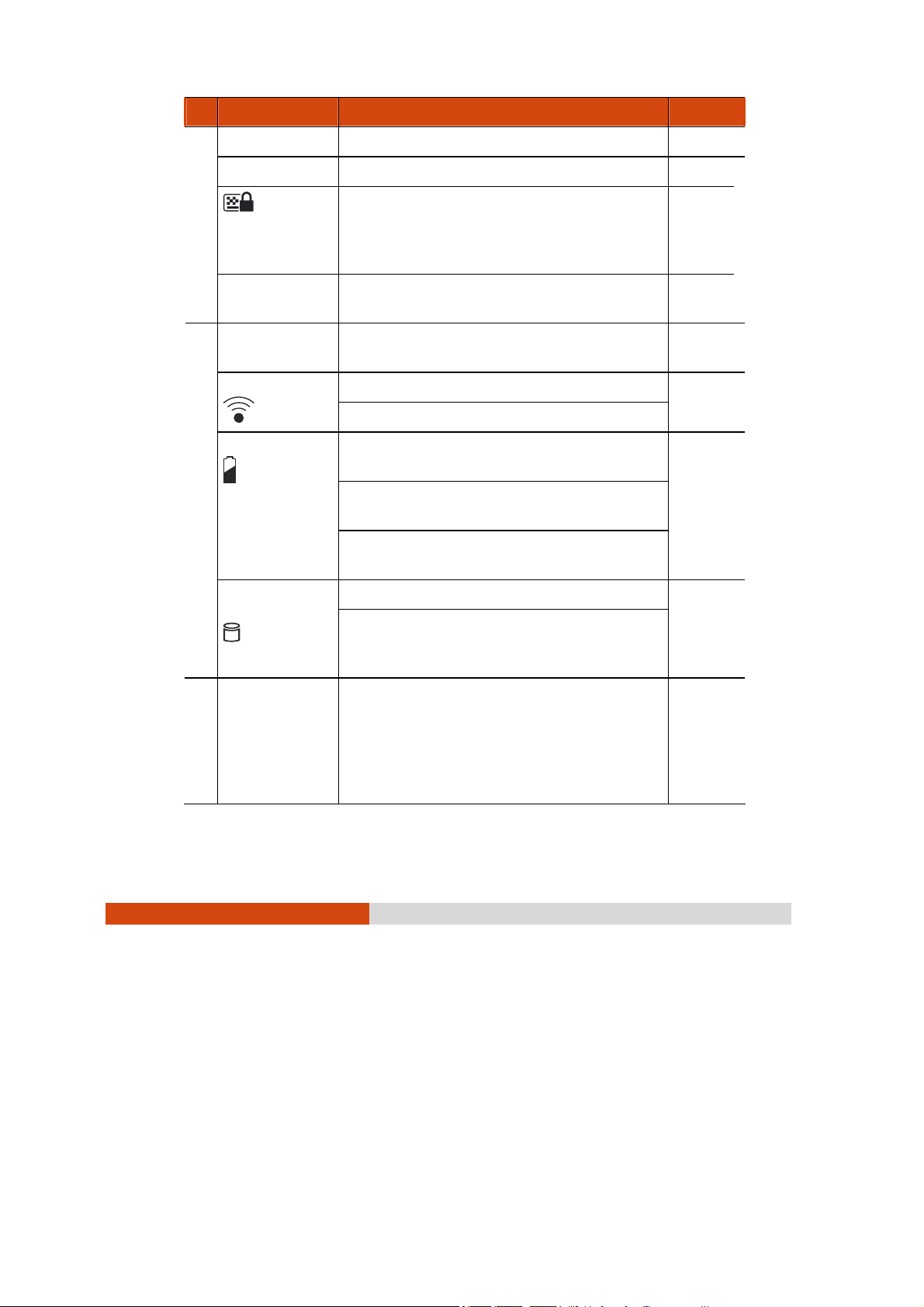
Ref Component Description See Also
Quick Buttons
q
Fn
Menu
Indicators
r
WLAN/WWAN
Battery Charge
Toggles the Fn keylock ON and OFF. P. 2-9
Toggles the keypad lock ON and OFF by
pressing for three seconds to prevent
accidental pressing of keypad during
transport.
Toggles the “OSD Control Panel” utility ON
and OFF.
Show the current status of the tablet PC’s
devices.
Lights green when WLAN is on.
Lights amber when WWAN is on.
Lights green when the battery is fully
charged.
Lights amber when the battery is being
charged.
Blinks red when the battery’s capacity is
below 10%.
P. 2-9
P. 2-9
P. 2-14
P. 3-3
Hard Disk Drive /
Heater (option)
Numeric Keypad
s
Lights green when hard disk drive is in use.
Lights red when optional heater is on
(temperature is lower than 5
booting your tablet PC).
Facilitates entering of numbers, also
includes the Del (Delete) and Ent (Enter)
keys. When Fn keylock is on, the alternative
function of a key is activated. The
alternative functions are identified by the
color of orange on the keytop.
o
C when
Getting Started 1-9
P. 2-4
Page 16
Page 17
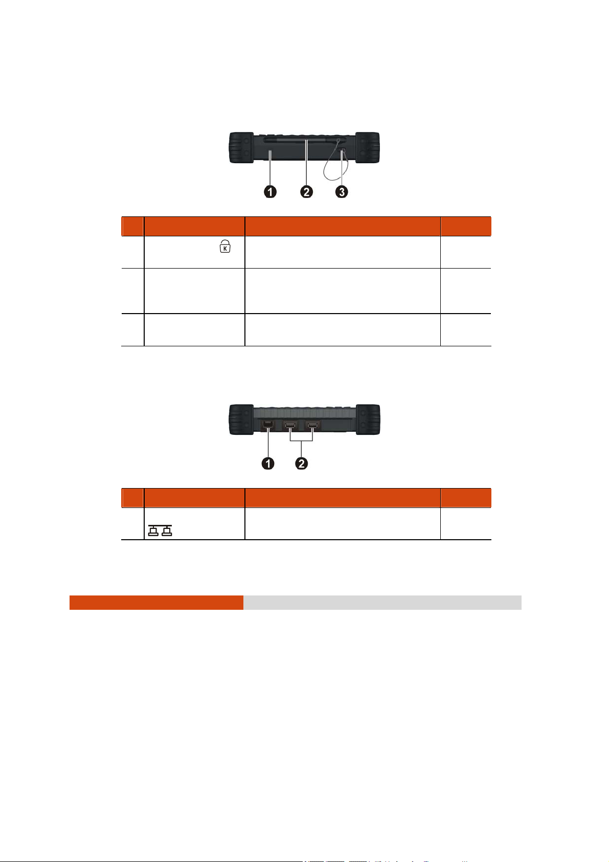
Right-Side Components
Ref Component Description See Also
Kensington Lock
n
Touchscreen Pen
o
Tether Hole
p
Locks the tablet PC to a stationary
object for security.
Serves as the input device by tapping
on the touch screen to make
selections and enter information.
Touchscreen pen tethered to this
hole.
P. 7-2
P. 2-7
Left-Side Components
Ref Component Description See Also
RJ-45 Connector
n
Connects the LAN cable. P. 2-13
Getting Started 1-11
Page 18
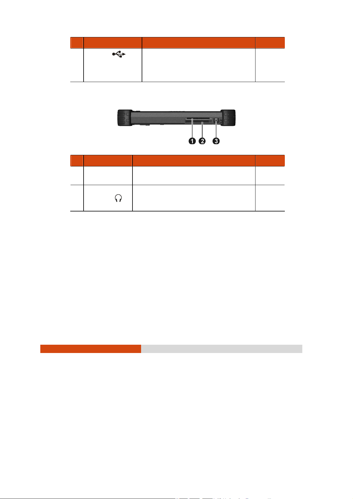
Ref Component Description See Also
USB Ports
o
Each of the two ports connects a USB
device, such as a USB flash disk,
printer, digital camera, joystick, and
more.
P. 4-2
Top Components
Ref Component Description See Also
n
o
Smart Card
Reader
Audio Output
Connector
Accepts a smart card for additional
security feature.
Connects a set of headphones, external
speakers with amplifier, or an audio
recording device.
P. 4-3
P. 2-11
1-12
Getting Started
Page 19
Page 20

Page 21

Chapter 2
Operating Your Tablet PC
This chapter provides information about the use of the tablet PC.
If you are new to tablet PCs, reading this chapter will help you learn the
operating basics. If you are already a computer user, you may choose to
read only the parts containing information unique to your tablet PC.
CAUTION: The tablet PC can get uncomfortably warm when you use it in high
temperatures. As a safety precaution in such a circumstance, do not place the
tablet PC on your lap or touch it with your bare hands for extended periods of time.
Prolonged body contact can cause discomfort and potentially a burn.
Operating Your Tablet PC 2-1
Page 22

Starting and Stopping the Tablet PC
There are a number of ways to start and stop the tablet PC.
Starting the Tablet PC
You always start the tablet PC using the power button.
A tablet PC starts up with an operating system (OS) existing on the storage
device such as the hard disk. The tablet PC will automatically load the OS
after you turn it on. This process is called booting.
NOTE: An operating system is the platform for all your software application
programs to run on. Your tablet PC uses the Microsoft Windows XP Tablet PC
edition operating system.
Stopping the Tablet PC
When you finish a working session, you can stop the tablet PC by turning
off the power or leaving the tablet PC in Standby or Hibernation mode:
To stop in this
mode...
Off Follow the shutdown procedure of your
operating system. This can prevent loss
of unsaved data or damage to your
software programs.
If the system is locked up because of
hardware or software problems, press
the power button to turn off the tablet
PC.
Standby Depending on your settings in Windows,
you can place the tablet PC in Standby
mode by pressing the power button.
2-2
Operating Your Tablet PC
Do this... To start up or
resume again
Press the power
button.
Press the power
button.
Page 23

To stop in this
mode...
Hibernation Depending on your settings in Windows,
you can place the tablet PC in
Do this... To start up or
resume again
Press the power
button.
Hibernation mode by pressing the
power button.
If you choose to stop in Standby or Hibernation mode, you can return to
where you left off the next time you start up the tablet PC. (See “Power
Management” in Chapter 3 for more information.)
Operating Your Tablet PC 2-3
Page 24
Using the Keypad
Your keypad can be divided into two major categories:
z Numeric, Delete (Del), and Enter (Ent) keys
z Cursor-control keys
NOTE: To use the keypad during poor lighting conditions, turn the keypad
backlight ON by pressing the Fn button, then press the “8” (
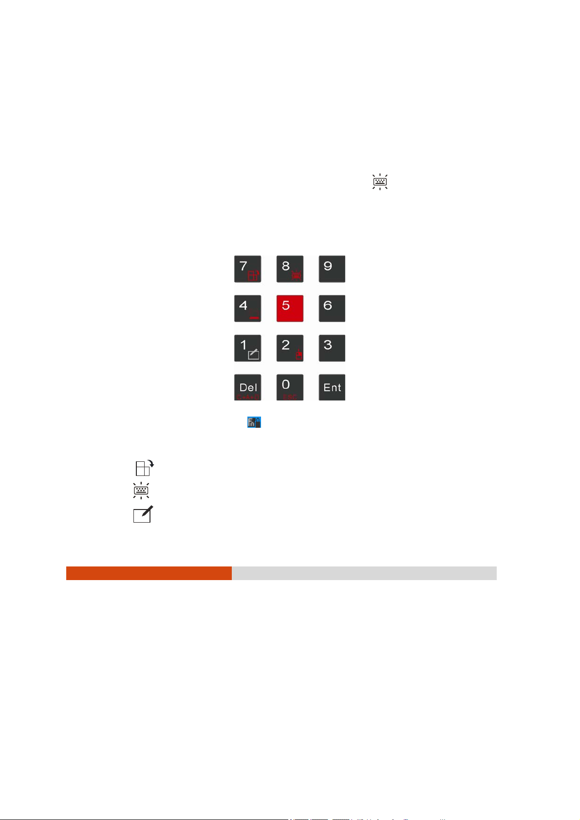
Numeric Keypad with Secondary Functions
The 12-key numeric keypad with Delete and Enter keys is shown next:
) button.
When the Fn keylock is ON (
use the following secondary functions with orange color on top of each
button.
z switches between landscape and portrait LCD display.
z switches the keypad backlight ON and OFF.
z switches the touchscreen OFF and ON.
2-4
Operating Your Tablet PC
icon appears on the system tray), you can
Page 25
z switches the sunlight-readable mode ON and OFF.
z serves as the mouse right-click button.
z C+A+D serves as the Ctrl+Alt+Del key combination.
z ESC serves as the Escape key.
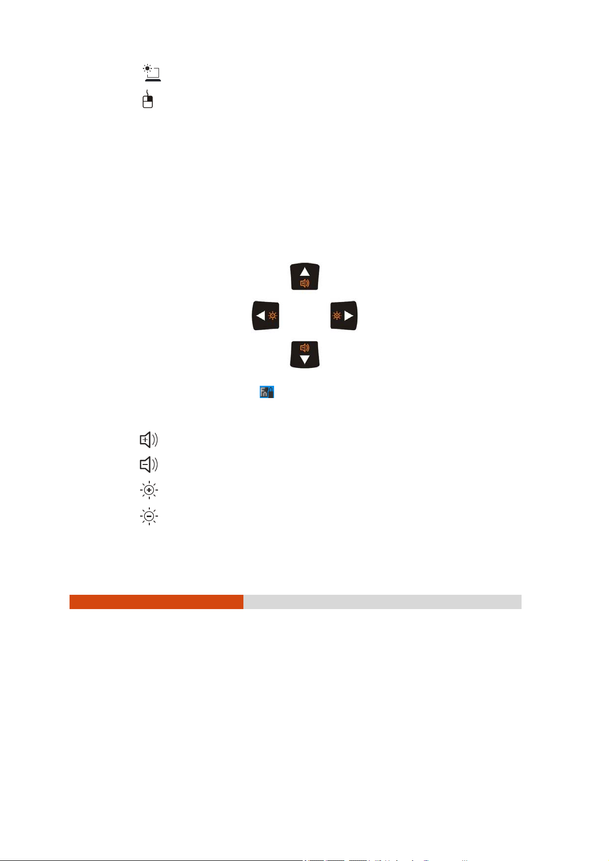
Cursor-Control Keys with Secondary Functions
The word “cursor” refers to the indicator on the screen (except for pointer
on screen) that lets you know exactly where on your screen anything you
type will appear. It can take the form of a vertical or horizontal line, a
block, or one of many other shapes.
When the Fn keylock is ON (
icon appears on the system tray), you can
use the following secondary functions with orange color on top of each
button.
z increase the sound volume of your tablet PC.
z decrease the sound volume of your tablet PC.
z increase the brightness of LCD display.
z decrease the brightness of LCD display.
Operating Your Tablet PC 2-5
Page 26

Using the On-screen Keyboard
Use the on-screen keyboard to enter text and perform various keyboard
functions.
1. Click the on-screen keyboard icon (
system tray and the software keyboard will appear onscreen.
2. Tap the characters on the on-screen keyboard with the touchscreen
pen.
NOTE: To protect the LCD display, use the touchscreen pen on your
touchscreen.
) located on the Windows
2-6
Operating Your Tablet PC
Page 27
Using the Touchscreen Pen
NOTE: The touchscreen function is not available when running the BIOS Setup
program or when using the full screen in DOS mode.
CAUTION: Do not use a sharp object such as a ballpoint pen or pencil on the
touchscreen. Doing so may damage the touchscreen surface. Use your finger or
the included touchscreen pen. A screen protector film has been attached to the
screen before shipment. The film is a consumable, which will be worn out after a
period of use (6 months in average). You can purchase a new one when
replacement is required.
The touchscreen is a touch-sensitive device that allows you to easily use
the tablet PC without a mouse or touchpad to communicate with the
tablet PC by controlling the location of the pointer on the screen and
making selection with the buttons.
Operating Your Tablet PC 2-7
Page 28

Here are some common terms that you should know when using the
touchscreen:
Term Action
Click/Point Tap gently on the touchscreen.
Double-click Tap twice on the touchscreen rapidly.
Drag and
drop
Press lightly on the touchscreen and move your finger
until you reach your destination (drag). Finally, release
your finger (drop) when you finish dragging your
selection to the destination. The object will drop into
the new location.
2-8
Operating Your Tablet PC
Page 29
Using the Quick Buttons
Located on top of the keypad are three quick buttons:
z Fn button toggles the Fn keylock ON and OFF ( icon appears on the
system tray when ON). You can use the secondary functions of
keypad buttons with orange color on top of each button (as
described in the “Using the Keypad” section earlier in this chapter).
z button toggles the keypad lock ON and OFF. Press the button to
turn on or press continuously for more than three seconds to turn off.
This would prevent accidental pressing of the keypad buttons during
transport.
z Menu button toggles the OSD Control Panel utility ON and OFF. Upon
pressing it the following screen appears (see chapter 6 for more
details).
Operating Your Tablet PC 2-9
Page 30

Using the Video Features
The video subsystem of your tablet PC features:
z 8.4-inch wide TFT (Thin-Film Transistor) color LCD with SVGA transmissive
display
z Toggle display between landscape view and portrait view using the
LCD rotate button
z Built-in light sensor to automatically adjust the LCD brightness
z Manually adjust the display brightness using the LCD brightness up
) and down ( ) buttons
(
z Power Management
z Sunlight-readable LCD display using the sunlight-readable mode
button
(option)
Configuring the Display Modes
Your tablet PC has been set to a default resolution and number of colors
before shipment. You can view and change display settings through your
operating system. See your operating system documentation or online
help for specific information.
2-10
Operating Your Tablet PC
Page 31

Using the Audio Features
The audio subsystem of your tablet PC features:
z High density audio codec
z Manually adjust the sound volume using the sound volume up ( )
and down (
z Audio-out connector ( ) (n)
z Integrated speaker (o)
) buttons
Ways of playing and recording sound vary with the operating system
used. See your operating system documentation or online help for specific
information.
Operating Your Tablet PC 2-11
Page 32

Connecting Audio Devices
For higher audio quality, you can send sound through external audio
devices such as speakers, headphones, or earphone set using the
audio-out connector.
NOTE:
z After connecting an external audio device, make sure that you specify the use
of the correct audio device in Windows.
z When using the external speakers/headphones, you cannot use the internal
one.
2-12
Operating Your Tablet PC
Page 33

Using the Communication Features
Using the LAN
The internal 10/100/1000Base-T LAN (Local Area Network) module allows
you to connect your tablet PC to a network. It supports data transfer rate
up to 1000 Mbps.
To connect the network cable to the LAN module, connect one end of
the LAN cable to the RJ-45 connector (
other end to the network hub.
) on the tablet PC and the
Using the Wireless LAN
The WLAN features include:
z Peer-to-Peer (Ad-Hoc) and Access Point (Infrastructure) modes
support
z WEP (Wired Equivalent Privacy) 64/128-bit data encryption
z IEEE 802.11b/g standard compliance
Technology 802.11b 802.11g
Stated Maximum
Throughput (Mbps)
Data Rates (Mbps) 11, 5.5, 2, 1 54, 36, 18, 9
Band (GHz) 2.412 ~ 2.462 2.4
11 54
Operating Your Tablet PC 2-13
Page 34

Modulation
Technology
DSSS (Direct Sequence
Spread Spectrum)
OFDM (Orthogonal
Frequency Division
Multiplexing)
NOTE: 802.11g mode is backward compatible with 802.11b mode.
Turning Off/On the WLAN Radio
NOTE: The FAA (Federal Aviation Agency) has deemed it unsafe to operate
wireless devices in aircraft as this may interfere with flight safety. Remember to
turn off wireless LAN when using your tablet PC in the airplane.
1. Press the Menu button on your tablet PC to start up the OSD Control
Panel utility.
2. Click the RF button to switch the WLAN radio on/off, indicated by the
WLAN indicator (
) glowing in green when on.
If you need to temporarily turn off the radio, click the RF button. To resume
network connection, click the RF button again. Upon restarting your
system, wireless LAN radio would be on even if you turned it off before
system shutdown.
2-14
Operating Your Tablet PC
Page 35

It takes approximately 30 seconds for your tablet PC to make a successful
WLAN connection and approximately 10 seconds to disconnect.
Connecting to a Wireless Network
To connect to a wireless network:
1. Make sure that the wireless LAN radio is “on” indicated by the wireless
LAN indicator (
) glowing in green.
2. Double-click the Wireless Network Connection icon
Windows system tray. If any wireless network is detected, the following
window appears on screen.
3. Click to select a wireless network to connect to, and then click
Connect.
4. Depending on the settings, you may be asked to enter a WEP key
(refer to your Windows online help for more information on setting a
wireless network connection).
located on your
Operating Your Tablet PC 2-15
Page 36
Using the
Depending on your model, your tablet PC may incorporate the Bluetooth
capability for short-range (about 10 meters) wireless communications
between devices without requiring a cable connection.
With Bluetooth, data can be transmitted through walls, pockets and
briefcases as long as two devices are within range. By default, your tablet
PC’s Bluetooth feature is active (always ON) upon booting your tablet PC
and is in the general discoverable and pairable mode.
The status of the Bluetooth connection is indicated by the Bluetooth icon
located in the system tray in the lower-right part of the screen.
Status Icon
On
Connected
You can use the Bluetooth Utility to configure Bluetooth connection
settings and transfer files.
Bluetooth
Connecting to Another
®
Wireless Feature
®
(blue with white logo).
(blue with green logo)
®
Bluetooth
Device
1. Make sure that the target Bluetooth device is turned on, discoverable
and within close range. (See the documentation that came with the
Bluetooth device.)
2. Right-click (press lightly until a pop-up menu appears) the
then click Add New Connection.
2-16
Operating Your Tablet PC
icon, and
Page 37
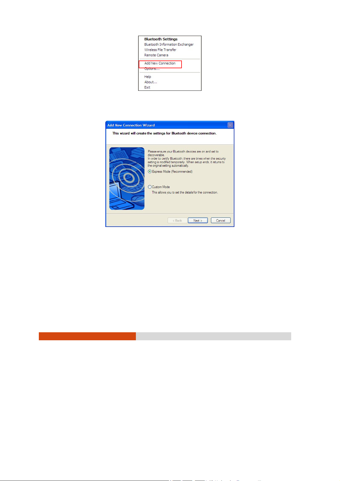
3. The Add New Connection Wizard window appears. Select Express Mode
(Recommended), and then click Next.
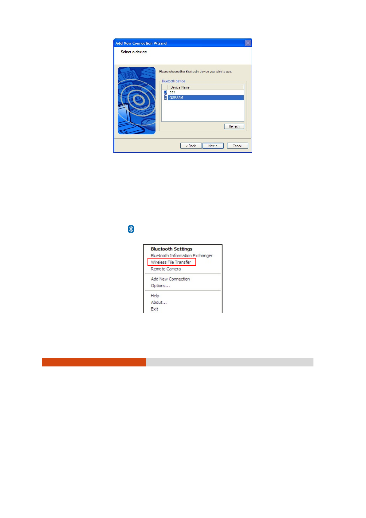
4. Select the device to connect to and click Next.
Operating Your Tablet PC 2-17
Page 38
5. Depending on the type of Bluetooth device that you want to connect
to, you will need to enter the pertinent information.
Sending a File
1. Make sure that the target Bluetooth device is turned on, discoverable
and within close range. (See the documentation that came with the
Bluetooth device.)
2. Right-click the
2-18
Operating Your Tablet PC
icon, and then click Wireless File Transfer.
Page 39

Page 40

Page 41

Unlock
position
4. Remove the two screws if existing (
battery pack off the computer (
). Pull on the ribbon strip to lift the
n
).
o
5. Locate the SIM card slot and push the SIM card into the slot. Make sure
the beveled corner on the SIM card is facing towards the tablet PC
and that the golden contact area on the card is facing downwards.
Operating Your Tablet PC 2-21
Page 42
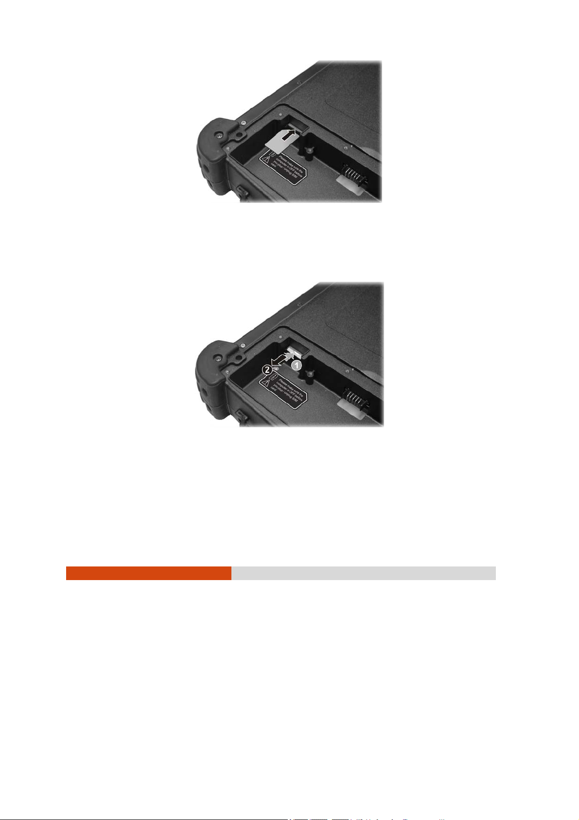
To remove the SIM card, just push in (n) the SIM card to pop-out (o)
and remove the card.
6. Fit the battery pack into place and secure with two screws.
7. Replace the battery cover and turn the latch clockwise to the lock
position.
2-22
Operating Your Tablet PC
Page 43

WARNING: Keep all SIM cards out of the reach of small children. For availability
and information on using SIM card services, contact your SIM card vendor. This
may be the service provider, network operator, or other vendor.
Operating Your Tablet PC 2-23
Page 44

Page 45

Chapter 3
Managing Power
Your tablet PC operates either on external AC power or on internal
battery power.
This chapter tells you how you can effectively manage power. To
maintain optimal battery performance, it is important that you use the
battery in the proper way.
Managing Power 3-1
Page 46

AC Adapter
CAUTION:
z The AC adapter is designed for use with your tablet PC only. Connecting the
AC adapter to another device can damage the adapter.
z The AC power cord supplied with your tablet PC is for use in the country
where you purchased your tablet PC. If you plan to go overseas with the tablet
PC, consult your dealer for the appropriate power cord.
z When you disconnect the AC adapter, disconnect from the electrical outlet
first and then from the tablet PC. A reverse procedure may damage the AC
adapter or tablet PC.
z When unplugging the connector, always hold the plug head. Never pull on the
cord.
The AC adapter serves as a converter from AC (Alternating Current) to DC
(Direct Current) power because your tablet PC runs on DC power, but an
electrical outlet usually provides AC power. It also charges the battery
pack when connected to AC power.
The adapter operates on any voltage in the range of 100~240 V AC.
3-2
Managing Power
Page 47

Battery Pack
The battery pack is the internal power source for the tablet PC. It is
rechargeable using the AC adapter.
The operating time of a fully charged battery pack depends on how you
are using the tablet PC. When your applications often access peripherals,
you will experience a shorter operating time.
NOTE: Care and maintenance information for the battery is provided in the
“Battery Pack Guidelines” section in Chapter 7.
Charging the Battery Pack
NOTE:
z Charging will not start if the battery’s temperature is below 0 °C (32 °F). It is
also recommended not to charge the battery when temperature is above 35
°C (95 °F).
z To prevent damage, the charging process may stop and the Battery Charge
Indicator flashes red when the environmental temperature gets above 55 °C
(131 °F).
z During charging, do not disconnect the AC adapter before the battery has
been fully charged; otherwise you will get a prematurely charged battery.
To charge the battery pack, connect the AC adapter to the tablet PC
and an electrical outlet. The Battery Charge Indicator (
PC glows amber to indicate that charging is in progress. You are advised
to keep the tablet PC power off while the battery is being charged. When
the battery is fully charged, the Battery Charge Indicator glows green.
) on the tablet
It takes approximately 3 hours to fully charge the Li-Ion battery pack at a
room temperature of 25 °C (may need a longer charging time at lower
temperatures).
CAUTION: After the tablet PC has been fully recharged, do not immediately
disconnect and reconnect the AC adapter to charge it again. Doing so may
damage the battery.
Managing Power 3-3
Page 48

NOTE: The battery level may automatically lessen due to the self-discharge
process (0.21% per day), even when the battery pack is fully charged (100%).
This happens no matter if the battery pack is installed in the tablet PC.
Initializing the Battery Pack
You need to initialize a new battery pack before using it for the first time or
when the actual operating time of a battery pack is much less than
expected.
Initializing is the process of fully charging, discharging, and then charging.
It can take several hours.
1. Make sure that the tablet PC power is turned off. Connect the AC
adapter to fully charge the battery pack.
2. After the battery pack is fully charged, turn on the tablet PC. Press the
Ent key when the prompt appears on the screen during system startup.
The prompt shows up on the screen for only a few seconds. You must
press the Ent key quickly.
3. A small window appears, select Launch System Setup to invoke the
program.
4. Disconnect the AC adapter and leave the tablet PC on until the
battery is fully discharged. The tablet PC will shut down automatically.
5. Connect the AC adapter to fully charge the battery pack.
Checking the Battery Level
NOTE: Any battery level indication is an estimated result. The actual operating
time can be different from the estimated time, depending on how you are using
the tablet PC.
By Operating System
You can check the approximate battery level using the battery meter
function of the operating system. To read the battery level in Windows,
3-4
Managing Power
Page 49

click the icon on the taskbar. (Click the icon if the tablet PC is using
AC power.)
By Gas Gauge
On the exterior side of the battery pack is a gas gauge for displaying the
estimated battery charge. When the battery pack is not installed in the
tablet PC and you want to know the battery charge, you can press the
switch with a pointed device to see the corresponding value of indicator
segment that light green. The value of the corresponding green segment
indicates the relative percentage of the battery charge. The battery pack
is fully discharged when you see no segment glowing green.
Switch
Replacing the Battery Pack
CAUTION:
z There is danger of explosion if the battery is incorrectly replaced. Replace the
battery only with the tablet PC manufacturer’s optional battery packs. Discard
used batteries according to the dealer’s instructions.
z Do not attempt to disassemble the battery pack.
If you often rely on battery power for a long period of time while traveling,
you may consider the purchase of an additional battery pack from your
dealer and keep it with you in a fully charged state as a backup.
To replace the battery pack, follow these steps:
Managing Power 3-5
Page 50

1. Make sure that the tablet PC is not turned on or connected to AC
power.
2. Place the tablet PC upside down.
3. Lift the latch handle of the battery cover and turn it counterclockwise
to the unlock position. Then, detach the cover from the tablet PC.
Unlock
position
4. Remove the two screws if existing (
battery pack off the computer (
3-6
Managing Power
). Pull on the ribbon strip to lift the
n
).
o
Page 51

5. Fit another battery pack into place.
6. Replace the battery cover and turn the latch clockwise to the lock
position.
Battery Low Signals and Actions
Battery Low occurs when the battery has approximately 10% (Windows
default setting) of its charge remaining. The tablet PC’s Battery Charge
Indicator (
NOTE: You can set up your threshold and signals of Battery Low under Windows.
Immediately save your data upon Battery Low. The remaining operating
time depends on how you are using the tablet PC. If you are using the
audio subsystem, hard or USB flash disk, the battery might run out of charge very
quickly.
Always respond to Battery Low by placing your tablet PC on the Standby
or Hibernation mode, turning off the tablet PC, or connecting the AC
adapter. If you do not take any action, the tablet PC will automatically
hibernate and turn off.
) blinks red to alert you to take actions.
Managing Power 3-7
Page 52

CAUTION: If you fail to save your data when the battery completely runs out of
charge, then you lose your data.
3-8
Managing Power
Page 53

Power Management
Your tablet PC supports ACPI (Advanced Configuration and Power
Interface) for power management. The power management feature
allows you to reduce the power consumption for energy saving.
With an ACPI-compliant operating system such as Windows, power supply
to different tablet PC components is controlled on an as-needed basis.
This allows maximum power conservation and performance at the same
time.
In general, Windows’ power management works in this way:
What... When...
Power to the hard disk is turned off When the hard disk has been idle for
a set period.
Power to the display is turned off When the display has been idle for a
set period.
The tablet PC enters the Standby
mode. The hard disk and display
are turned off and the entire
system consumes less power.
The tablet PC enters the
Hibernation mode. (See the next
subsection for more information.)
* Depends on your settings in Windows.
For detailed information on power management, see Windows’ Help.
When the entire system has been
idle for a set period.
When you press the power button. *
When the entire system has been
idle for a set period.
When you press the power button. *
Managing Power 3-9
Page 54

Hibernation
NOTE: Make sure that the hibernation feature is enabled in the Hibernate tab of
the Power Options Properties from the Control Panel in Windows XP.
Hibernation is a very useful feature. People frequently open many
applications when they use computers. It takes some time to get all these
applications open and running, and normally they all have to be closed
before the computer can be turned off.
When you use the hibernation feature, you do not have to close the
applications. The tablet PC stores the state of your tablet PC to a file on
the hard disk and then shuts down. The next time you turn on your tablet
PC, you return to exactly where you left off.
3-10
Managing Power
Page 55

Power-Saving Tips
Aside from enabling your tablet PC’s power saving mode (see previous
section), you can do your part to maximize the battery’s operating time
by following these suggestions.
z Do not disable Power Management.
z Decrease the LCD brightness to the lowest comfortable level.
z Shorten the length of time before Windows turn off the display.
z Many USB devices use power just by being connected. If you use a
USB mouse, you can save power by disconnecting the mouse and
using the optional touchscreen pen. If you use a USB flash drive,
unplug it when you are not using it.
z Deactivate the Wireless LAN function if you are not using it (see
Chapter 2).
z Deactivate the Bluetooth wireless feature if you are not using it (see
Chapter 2).
z Turn off the tablet PC when you are not using it.
Managing Power 3-11
Page 56

Page 57

Chapter 4
Expanding Your Tablet PC
You can expand the capabilities of your tablet PC by connecting other
peripheral devices. When using a device, be sure to read the instructions
accompanying the device together with the relevant section in this
chapter.
Expanding Your Tablet PC 4-1
Page 58

Connecting a USB Device
Your tablet PC has two USB ports for connecting USB devices, such as a
digital camera, scanner, printer, modem, and mouse.
The USB ports support transfer rates up to 12 MB/s for USB 1.1 devices and
480 MB/s for USB 2.0 devices.
To connect a USB device, simply plug the device cable to one of the USB
ports (
).
4-2
Expanding Your Tablet PC
Page 59

Using Smart Cards
Your tablet PC has a smart card slot for additional security feature,
providing tamper-proof storage of user and account identity. A smart
card is a type of plastic card embedded with a computer chip that stores
and transacts data between you (user) and the tablet PC.
You need to install third-party smart card software to take advantage of
the smart card feature.
Inserting and Removing a Smart Card
To insert a smart card:
1. Locate the smart card slot on the top of the tablet PC.
2. Slide the smart card, with its label and embedded computer chip
facing up into the slot.
3. When a new card is seated, use the third-party smart card software to
allow your tablet PC to read it.
To remove a smart card:
1. Make sure that the third-party smart card software is not accessing the
smart card.
2. Pull the card out of the slot.
Expanding Your Tablet PC 4-3
Page 60

4-4
Expanding Your Tablet PC
Page 61
Using the Docking Station
A docking station is available as an option. This device eliminates the
hassles of having you connect and disconnect the various cables when
carrying your tablet PC around and allows a variety of peripherals to be
connected including a headphone or microphone, etc. The docking
station connects to the docking connector at the front of your tablet PC.
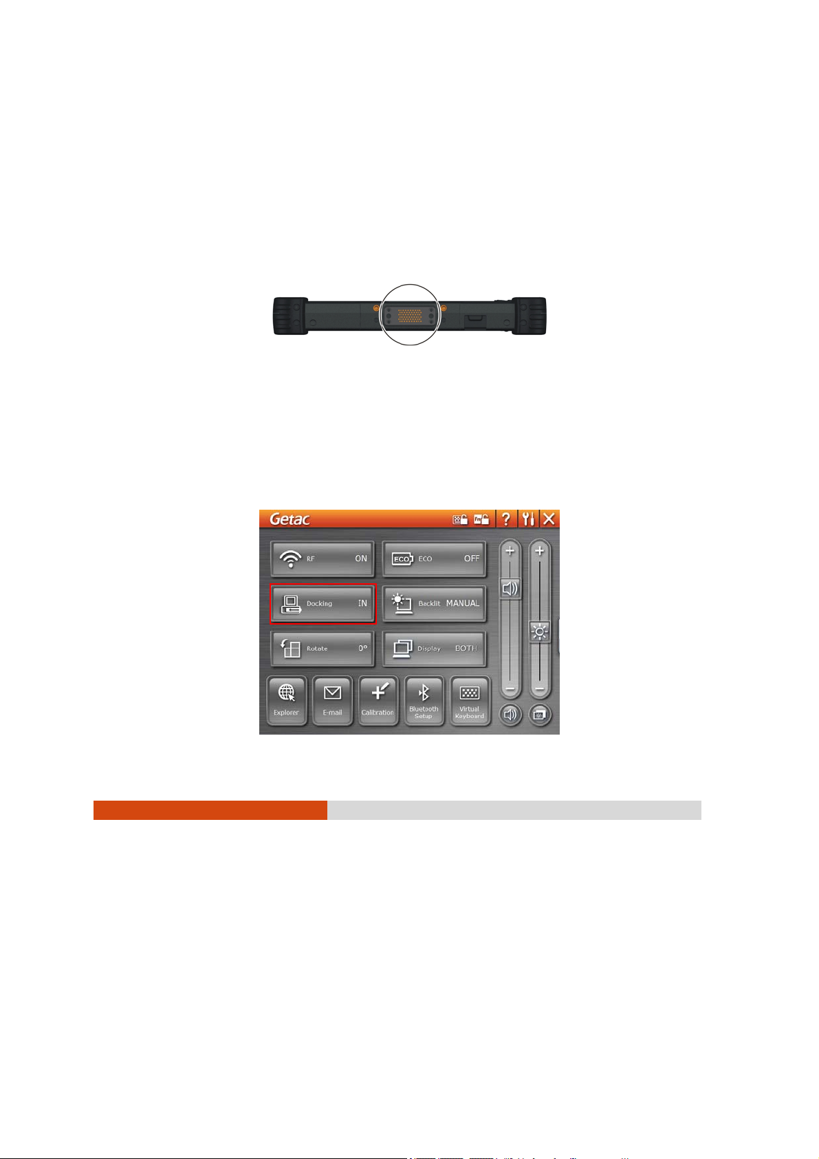
1. Locate the docking connector.
2. Connect your docking station to the docking connector.
For more detailed information, refer to the Operating Instructions of the
docking station.
NOTE: Hot/warm docking and hot/warm undocking are possible with the docking
connector but it is recommended that prior to undocking, press the Menu button
and the OSD Control Panel appears. Click the Docking button.
Expanding Your Tablet PC 4-5
Page 62

Page 63

Chapter 5
Using BIOS Setup and
System Recovery
BIOS Setup Utility is a program for configuring the BIOS (Basic Input/ Output
System) settings of the tablet PC. BIOS is a layer of software, called
firmware, that translates instructions from other layers of software into
instructions that the tablet PC hardware can understand. The BIOS settings
are needed by your tablet PC to identify the types of installed devices
and establish special features.
System Recovery reinstalls Windows to your system and configures it to the
system’s factory default settings.
This chapter tells you how to use the BIOS Setup and System Recovery.
Using BIOS Setup and System Recovery 5-1
Page 64

BIOS Setup
When to Use BIOS Setup
When to Use
You need to run BIOS Setup Utility when:
z You see an error message on the screen requesting you to run BIOS
Setup Utility.
z You want to restore the factory default BIOS settings.
z You want to modify some specific settings according to the
hardware .
z You want to modify some specific settings to optimize the system
performance.
Starting BIOS Setup
NOTE:
z The BIOS Setup Utility screens shown in this chapter are for your reference
only. The actual items or settings on your tablet PC may differ.
z The BIOS Setup Utility program may have been updated after the publication
of this manual.
z The settings you select in your operating system might override similar
settings in BIOS Setup Utility.
To run BIOS Setup utility, press the Ent key when the prompt appears on the
screen during system startup. The prompt shows up on the screen for only
a few seconds. You must press the Ent key quickly. A small window
appears, select Launch System Setup. The BIOS Setup Utility main screen
appears as shown next.
5-2
Using BIOS Setup and System Recovery
Page 65

The BIOS Setup Utility screen can be divided into four areas:
z On the top is the menu bar containing the titles of the available
menus. Each menu title brings a specific menu.
z The left column of the menu displays the menu items.
z The right column of the menu provides more detailed information
when a menu item is highlighted.
z The bottom of the menu provides keyboard instructions for moving
around and making selections.
Moving Around and Making Selections
You must go through two or three levels to complete the setting for an
item. In most cases, there are two levels: menu title and submenu.
Use the keyboard to move around and make selections. Keyboard
information can be found at the bottom of the screen. A brief description
of keyboard usage is listed next:
Using BIOS Setup and System Recovery 5-3
Page 66

Key Function
← , → Selects a menu title.
↑ , ↓ Selects an item or option.
+ / – Changes the value.
Ent
NOTE: You can press the F1, F9, F10, –/+, and Esc keys by connecting a USB
keyboard to your tablet PC. Make sure that the item “Legacy USB Support” under
the Main menu is set at Enabled (default).
1) Brings up the sub-menu when available.
2) Opens or closes the option window when an item is
selected.
Information Menu
The Information menu contains the basic configuration information of the
system.
5-4
Using BIOS Setup and System Recovery
Page 67

Main Menu
The Main menu contains the system time and date, as well as the USB
setting of the system.
System Time sets the system time.
System Date sets the system date.
Power Button Delay allows you to prevent accidental pressing of the power
button.
Legacy USB Support enables the system’s support for Legacy USB device in
DOS mode.
Using BIOS Setup and System Recovery 5-5
Page 68

Advanced Menu
The Advanced menu contains the advanced settings as shown next.
Total Graphics Memory allows you to select the amount of total graphics
memory (pre-allocated + fixed + DVMT) for use by the internal graphics
device.
DVMT Graphics Memory shows the size of DVMT graphics memory.
HDD Preheat allows your system to automatically turn on the optional
heater when temperature of the hard disk drive is lower than 5
o
C.
NOTE: The optional heater can function when your tablet PC is connected to AC
power or using battery power but the preheat feature can only function when your
tablet PC is connected to AC power.
High Temperature Protection allows you to turn off hard disk drive power to
prevent damage to data when HDD temperature goes above the safe
range. System will also show a warning message.
5-6
Using BIOS Setup and System Recovery
Page 69

Security Menu
The Security menu contains the TPM (Trusted Platform Module) setting. The
TPM is a component on your tablet PC’s mainboard that is specifically
designed to enhance platform security above-and-beyond the
capabilities of today’s software by providing a protected space for key
operations and other security critical tasks. Using both hardware and
software, TPM protects encryption and signature keys at their most
vulnerable stages – operations when the keys are being used
unencrypted in plain-text form. TPM is specifically designed to shield
unencrypted keys and platform authentication information from
software-based attacks.
TPM Support enables or disables TPM support (see chapter 6 for details).
Current TPM State shows the current TPM state.
Change TPM State allows you to select between No Change, Clear,
Deactivate & D isable, and Enable & Activate.
Using BIOS Setup and System Recovery 5-7
Page 70

Boot Menu
The Boot menu sets the sequence of the devices to be searched for the
operating system.
The bootable devices will be automatically detected during POST and
shown here, allowing you to set the sequence that the BIOS uses to look for
a device from which to load the OS. Below is a brief description of
keyboard usage:
Key Function
↑ , ↓ Selects (highlight) a boot device.
1 to 4 Loads the default boot sequence.
NOTE: You can press the f, r, x, –/+, and Shift + 1 keys by connecting a USB
keyboard to your tablet PC. Make sure that the item “Legacy USB Support” under
the Main menu is set at Enabled (default).
5-8
Using BIOS Setup and System Recovery
Page 71
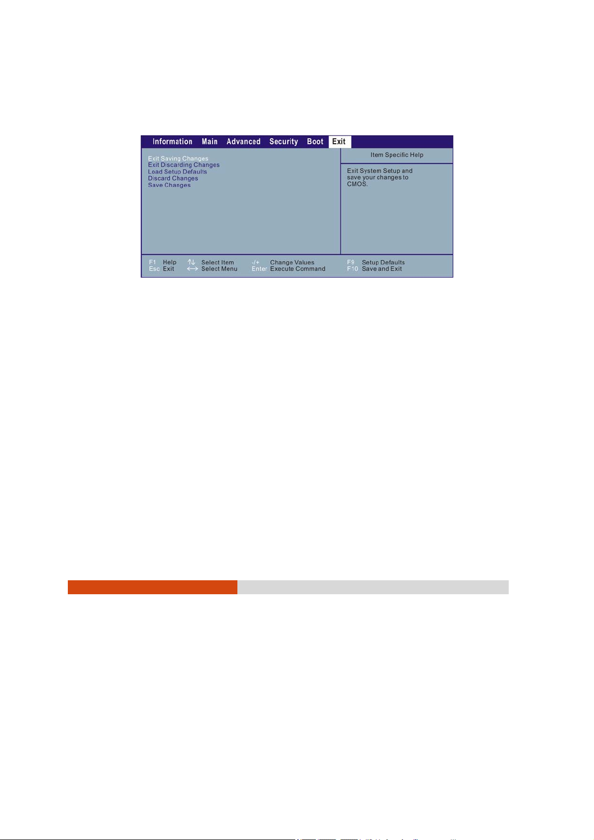
Exit Menu
The Exit menu displays ways of exiting BIOS Setup Utility. After finishing with
your settings, you must save and exit so that the changes can take effect.
Exit Saving Changes saves the changes you have made and exits BIOS Setup
Utility.
Exit Discarding Changes exits BIOS Setup Utility without saving the changes
you have made.
Load Setup Defaults loads the factory default values for all the items.
Discard Changes restores the previous values for all the items.
Saves Changes saves the changes you have made.
Using BIOS Setup and System Recovery 5-9
Page 72

System Recovery
You need to run System Recovery when:
z Your Windows operating system does not start at all.
z You want to restore the factory default Windows settings.
WARNING: Using this feature will reinstall Windows to your system and configure it to the
system’s factory default settings. All data on the hard disk drive will be lost.
To run System Recovery:
1. During system startup when the following screen appears, press Ctrl +
Alt + F2 keys for four seconds or press Ent and select HDI Recovery when a
small window appears on the screen.
2. The message
to factory default. All data on HDD will be lost
5-10
Using BIOS Setup and System Recovery
This will help you reinstall Windows to the whole HDD
appears on the
Page 73

screen to ask if you want to access System Recovery. Type 1 to
continue or type
0 to exit.
3. A warning message appears as follows:
****************************************
You must accept the following terms before performing the recovery
process:
1. The recovery software is solely the purpose of reinstalling or
restoring software associated with the hard disk of this operating
GETAC machine.
2. Except the above, no other use is granted hereunder.
****************************************
(1)Yes, I agree to the provisions of this agreement and wish to
continue.
(0)No, I do not agree to the provisions of this agreement and do
not wish to continue.
Type 1 to continue.
4. Type 1 again when the message
(1)Yes (0)No
appears onscreen.
Are you sure you want to recover now?
5. Your system will start the recovery process and Windows operating
system will be re-installed to its default setting.
Using BIOS Setup and System Recovery 5-11
Page 74

Page 75

Chapter 6
Using Special Utilities
Your tablet PC comes with an added security feature known as the TPM
(Trusted Platform Module) – a component on your tablet PC’s mainboard
that is specifically designed to enhance platform security above-andbeyond the capabilities of today’s software by providing a protected
space for key operations and other security critical tasks.
The OSD Control Panel utility allows you to activate or operate certain
functions on your tablet PC.
The G-Manager utility is a unified user interface utility that allows you to
manage and configure various system components.
This chapter describes how to use these utilities.
Using Special Utilities 6-1
Page 76

Using TPM (Trusted Platform Module)
TPM is a hardware-based security feature that can be used to create and
manage computer-generated digital certificates. When combined with
security software, the TPM enhances existing network and computer
security by enabling features such as file protection capabilities and
protected e-mail.
NOTE:
z Make sure you select Enable on the TPM Support item under the Security menu
of your BIOS Setup (see chapter 5 for details).
z Make sure you select Enable & Activate on the Change TPM State item under
the Security menu of your BIOS Setup (see chapter 5 for details).
z You only need to activate these items once.
You can use the certificates to:
z Send and receive secure email from email clients like Microsoft
Windows Mail/Outlook Express, Microsoft Outlook or Netscape
Messenger
z Set up browser (e.g. Netscape Navigator or Internet Explorer) and web
server (e.g. Microsoft Internet Information Server) for Client
Authentication
z Sign Microsoft Word macros
z Encrypt files and folders
z Secure network connections
NOTE: For information on using the program and the different security features,
click Start Æ All Programs Æ Infineon Security Platform Solution Æ Help.
6-2
Using Special Utilities
Page 77

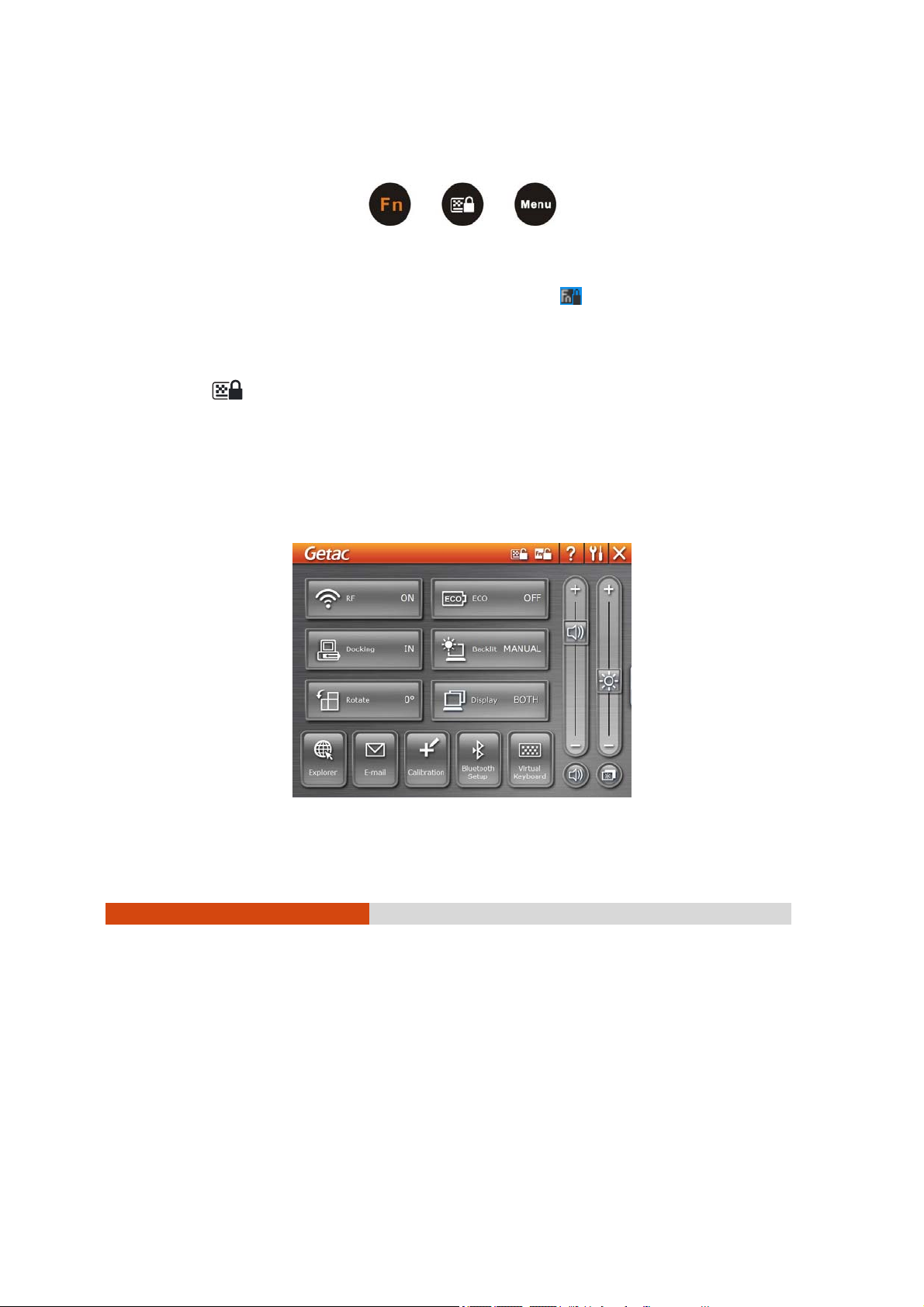
Using the OSD Control Panel
The OSD Control Panel allows you to activate or operate certain functions
on your tablet PC.
To open the OSD Control Panel, press the Menu button on your tablet PC.
The following screen appears.
Using Special Utilities 6-3
Page 78

The following table shows the various functions on the OSD Control Panel.
Operation OSD Control Panel Description
Switches the keypad lock ON and OFF. Press the button
one second to turn ON (lock) and continuously for
more than three seconds to turn OFF (unlock).
This would prevent accidental pressing of the keypad
buttons during transport.
Switches the Fn keylock ON and OFF (
on the system tray when ON).
icon appears
You can use the secondary functions of keypad buttons
with orange color on top of each button.
A Help file explaining the OSD Control Panel.
Turns on the Quick Button Setup utility (refer to the next
section for details).
Closes and exits the OSD Control Pane.
Switches the RF module OFF and ON (wireless LAN,
Bluetooth, 3G).
Upon restarting your system, wireless LAN radio would
be on even if you turned it off before system shutdown.
Toggles the system power saving mode between OFF /
Work / Quick and Power Saving.
While entering into power saving mode, the system will
turn down the panel backlight and sacrifices
processing speed to gain more battery life. The ECO
button works only when using battery power.
6-4
Using Special Utilities
The status would display IN when you connect your
tablet PC to a docking station.
To turn off power to the docking station without
disconnecting from your tablet PC, click the Docking
button.
Before removing your tablet PC from the docking
Page 79

Operation OSD Control Panel Description
station, make sure to click the Docking button to show
OUT.
Toggles between NORMAL, MAX, and AUTO brightness for
LCD backlight.
Rotates the LCD display orientation from default
landscape to 90
and vice versa.
o
portrait, 180o landscape, 270o portrait,
Toggles between LCD, VGA (external device e.g.,
monitor), and BOTH (LCD and external device).
Switches the display output when external devices are
connected. If the external device is not connected,
the choice would only be LCD. Upon restarting your
system, the setting would be LCD only.
®
Serves as the default Microsoft
Internet Explorer quick
launch button.
You can use the Quick Button Setup utility to assign a
different function to this button (refer to the next
section for details).
Serves as the default Microsoft
®
Outlook Express quick
launch button.
You can use the Quick Button Setup utility to assign a
different function to this button (refer to the next
section for details).
Serves as the default LCD display calibration tool quick
launch button.
You can use the Quick Button Setup utility to assign a
different function to this button (refer to the next
section for details).
Using Special Utilities 6-5
Page 80
Operation OSD Control Panel Description
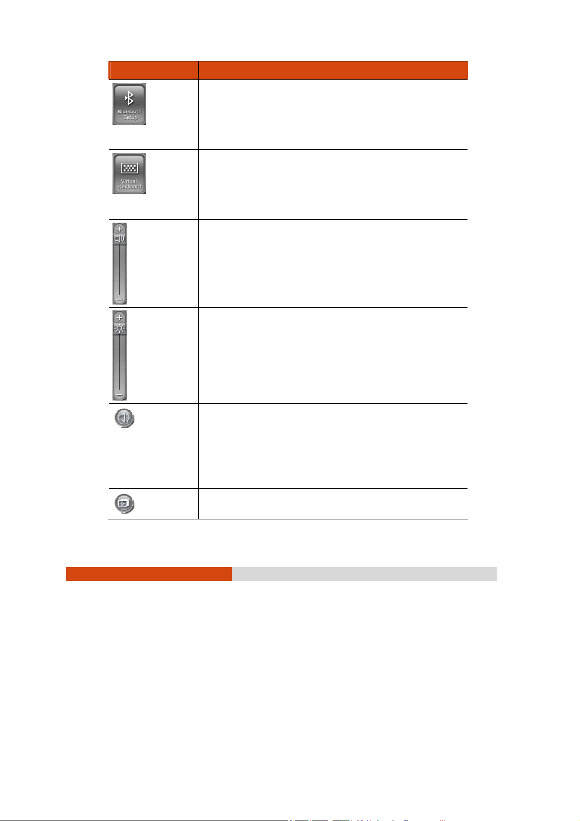
Serves as the default Bluetooth
®
launch button.
You can use the Quick Button Setup utility to assign a
different function to this button (refer to the next
section for details).
Serves as the default virtual keyboard quick launch
button.
You can use the Quick Button Setup utility to assign a
different function to this button (refer to the next
section for details).
Increases or decreases the sound volume. This function
adjusts the volume of sound output both from the
speakers and headphones. It is synchronized with your
Windows main volume controller.
Upon restarting your system, Windows will memorize the
last setting before system shutdown.
wireless setup quick
6-6
Using Special Utilities
Increases or decreases the LCD brightness level.
Upon restarting your system, Windows will memorize the
last setting before system shutdown.
Switches the system sound output OFF (mute) and ON.
This function mutes the sound output both from the
speakers and headphones. It is synchronized with your
Windows main volume controller.
Upon restarting your system, Windows will memorize the
last setting before system shutdown.
System enters “black-out” mode by turning off the LCD
display, LED indicators, touchscreen, and sound
Page 81

Operation OSD Control Panel Description
volume.
Press the power button (
from “black-out” mode.
) to wake up the system
Quick Button Setup Utility
By default, the five quick launch buttons on the OSD Control Panel have
pre-assigned functions.
The Quick Button Setup utility allows you to re-define the above five quick
launch buttons. To re-define:
1. Click the Quick Button Setup utility button (
Setup window appears as shown next.
) and the Quick Button
Using Special Utilities 6-7
Page 82
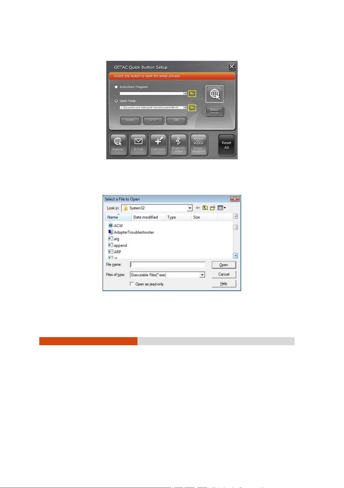
2. To re-assign a program to a button, click to select a particular button
to change (e.g., Explorer), then click the folder icon.
3. The Select a File to Open dialog box appears as shown next. Select the
desired program, then click Open to complete the process.
6-8
Using Special Utilities
Page 83

4. You can change the image appearing on the button by clicking the
Select Image icon.
5. The Select Picture dialog box appears as shown next. After selecting the
image file, the appropriate icon will then appear in the button.
6. Click Set to complete the changes.
Using Special Utilities 6-9
Page 84

Using the G-Manager Utility
G-Manager is a unified user interface utility that allows you to manage
and configure the following:
z System
z Battery
z Light Sensor
z ECO (economy mode)
z Ignition
z Monitoring
z Antenna
z GPS Status
Starting G-Manager
You can start up G-Manager by any of the following methods:
z Click Start Æ All Programs Æ GETAC Utility Æ G-Manager, or
z Right-click on the GETAC Utility icon (
and click G-Manager.
6-10
Using Special Utilities
) located on the system tray
Page 85
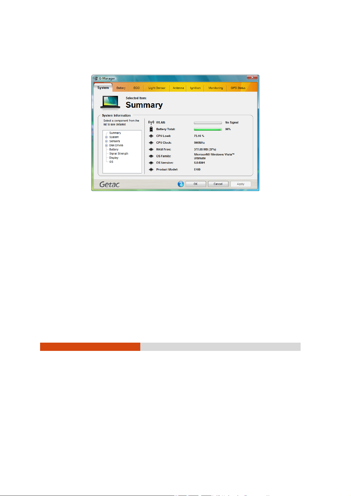
System Tab
The System tab provides an overview of the system status.
The component to be viewed is selected from the tree view list on the left
side of the screen. It contains eight major components namely:
z Summary
z System
z Sensors
z Disk Drives
z Battery
z Signal Strength
z Display
z OS (operating system)
Using Special Utilities 6-11
Page 86

The status of the selected component is displayed on the right side of the
screen.
Battery Tab
The Battery tab allows you to minimize deterioration of the battery thereby
ensuring a longer battery life. At most two batteries may be supported.
Press Battery 1 or Battery 2 to view the details and configuration settings of
each battery.
Battery Information
The upper portion of the Battery tab contains a live update of information
about the selected battery.
NOTE:
z When the percentage % Left is less than 10% then the value will be displayed
in red.
6-12
Using Special Utilities
Page 87
z When an abnormal battery condition is detected Battery Status value will be
displayed in red.
Charging Mode
The lower left portion of the Battery tab allows you to select the charging
mode.
z Normal Mode – the battery will be fully charged. When remaining
charge reaches below 95%, then charging will start until it is fully
charged.
z Economy Mode – to help prolong battery life the battery will be charged
up to 80% of its total capacity only. Highly recommended when you
are using AC power most of the time.
Gauge Reset
The lower right portion of the Battery tab allows you to discharge and
recharge the battery in order to activate certain physical attributes
periodically. The percentage bar shows the battery health.
The low health bar percentage indicates the poorer health of the battery,
therefore the need to perform the gauge reset in order to calibrate
battery’s capacity and improve the battery’s performance.
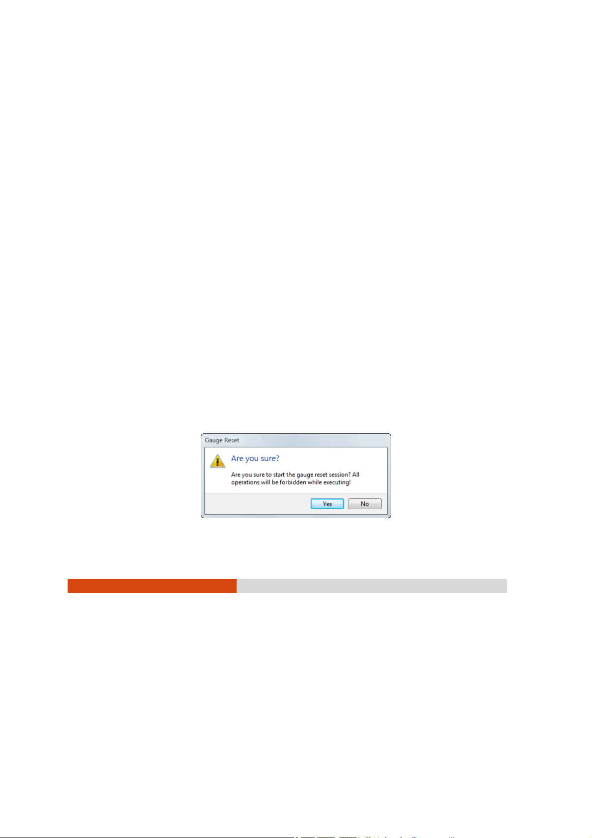
To perform a gauge reset:
1. Click Perform Gauge Reset to perform a gauge reset and the following
screen appears.
Using Special Utilities 6-13
Page 88
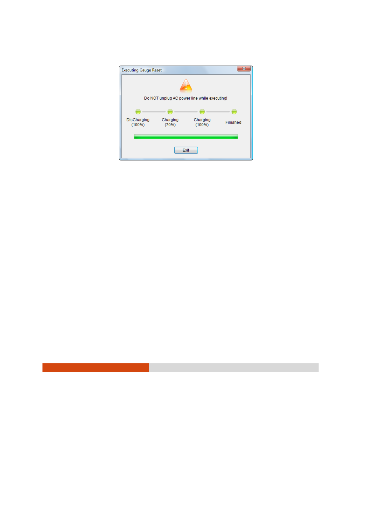
2. Click Yes to start the gauge reset session and the following screen
appears.
The percentage of completion will be shown on the progress bar.
Depending on the number of battery, the screen will show the
corresponding number of batteries to perform gauge reset. The value of
Working Status will show in red alternately.
You can click Cancel anytime to stop gauge reset.
NOTE: When a gauge reset is in progress, do not execute other operation except
to click Cancel to stop gauge reset.
6-14
Using Special Utilities
Page 89

Light Sensor Tab
The Light Sensor tab allows you to adjust the LCD brightness based on your
surrounding’s lighting condition.
Sensor Mode
The left portion of the Light Sensor tab allows you to select the sensor
mode.
z Normal – light sensor sensitivity is set at normal environment lighting
condition.
z Bright – light sensor sensitivity is set at bright environment lighting
condition (e.g. outdoors).
z Dark – light sensor sensitivity is set at dark environment lighting condition
(e.g. indoors, storage warehouse, etc.).
Using Special Utilities 6-15
Page 90

The lower left portion of the Light Sensor tab shows the selected sensor
mode’s graph.
The upper right portion of the Light Sensor tab shows the active profile
based on your selection on sensor mode.
The middle right portion of the Light Sensor tab shows the environment
luminance (degree of Lux from weak to bright) as detected by your tablet
PC’s light sensor.
The lower right portion of the Light Sensor tab allows your system to
illuminate the keypad in poor lighting environment by selecting the
checkbox Automatic Keyboard Backlit.
ECO Tab
The ECO tab allows you to manage the system’s power consumption.
NOTE: The items appearing on the ECO tab may differ depending on your model.
6-16
Using Special Utilities
Page 91

ECO Information
Depending on the system, the left portion of the ECO tab shows the
available profile to manage the system’s power consumption.
Active Profile
The right upper portion of the ECO tab shows the name of the current
profile selected.
Profile Settings
The lower right portion of the ECO tab contains the following:
z Turn on/off the following for power saving: WWAN, Bluetooth, WLAN,
and optical disk drive.
z Power Scheme – select Home/Office Desk, Portable/Laptop, Presentation, Always
On, Minimal Power Management, or Max Battery if your system is running
Windows XP. Select Balanced, High Performance or Power Saver if the system
is running Windows Vista. The setting here will correspond to your
settings in Windows. (See Windows Help for the description to each of
the power scheme.)
z Brightness – adjust the brightness setting from 0 ~ 63. This option is not
available on systems running Windows Vista.
z Default – revert back to original profile setting.
Using Special Utilities 6-17
Page 92
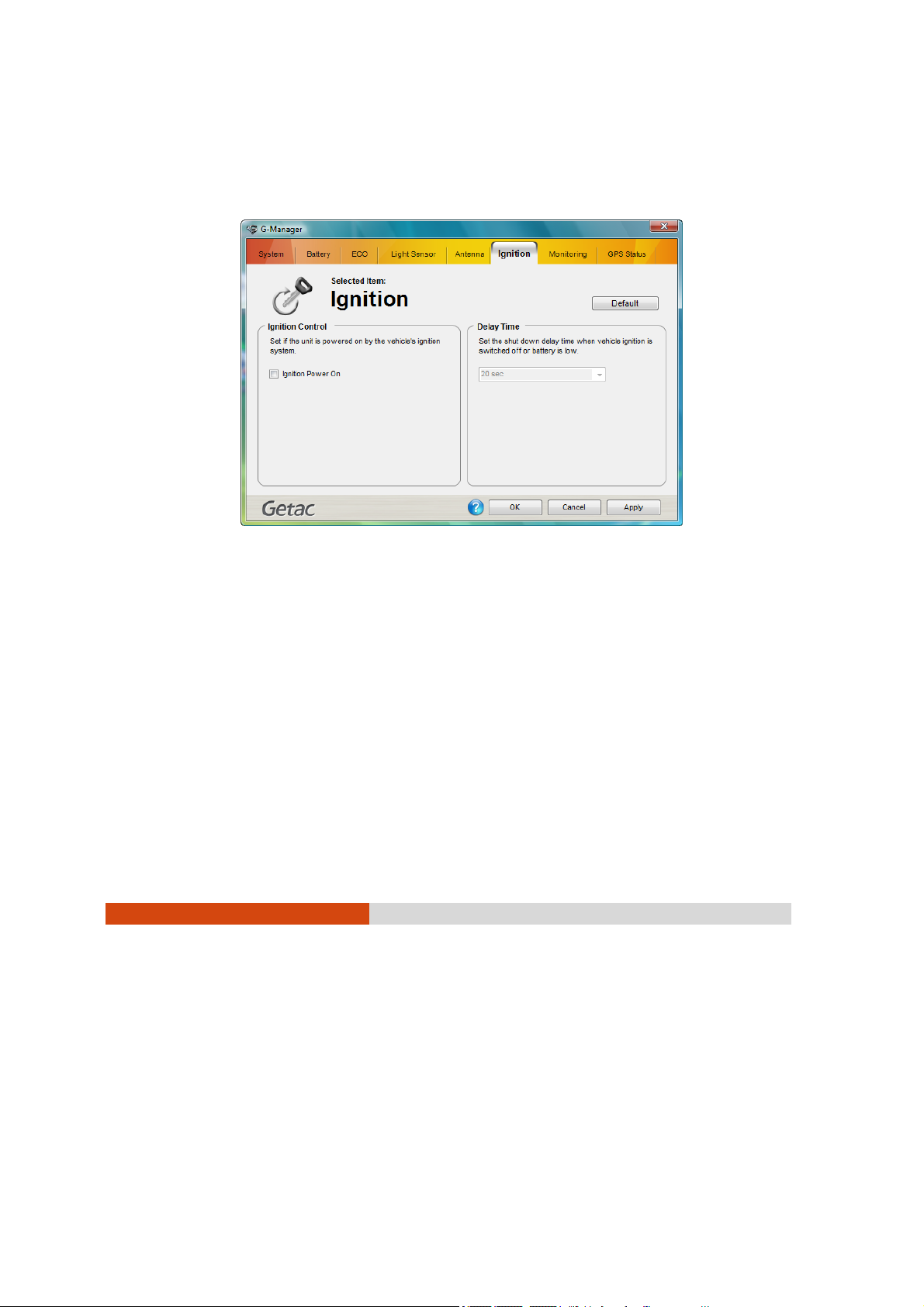
Ignition Tab
The Ignition tab allows you to set if the system is deriving power from your
vehicle.
Ignition Control
The left portion of the Ignition tab allows your system to derive power from
the vehicle as well as boot up your tablet PC by selecting the checkbox
Ignition Power On. Your tablet PC will also shutdown when you turn off
ignition to your vehicle. The amount of time between turning off your
vehicle and tablet PC shutdown would depend on your setting on the
next section Delay Time. This feature is only available when your tablet PC
is docked to the GETAC docking station.
6-18
Using Special Utilities
Page 93
Delay Time
The right portion of the Ignition tab allows you to set the delay time
(20 seconds, 30 seconds, 45 seconds, 1 minute, or 2 minute) to shut down
the system when you turn off vehicle ignition. This will help prevent the
tablet PC from using up the vehicle’s battery power thereby causing poor
vehicle startup.
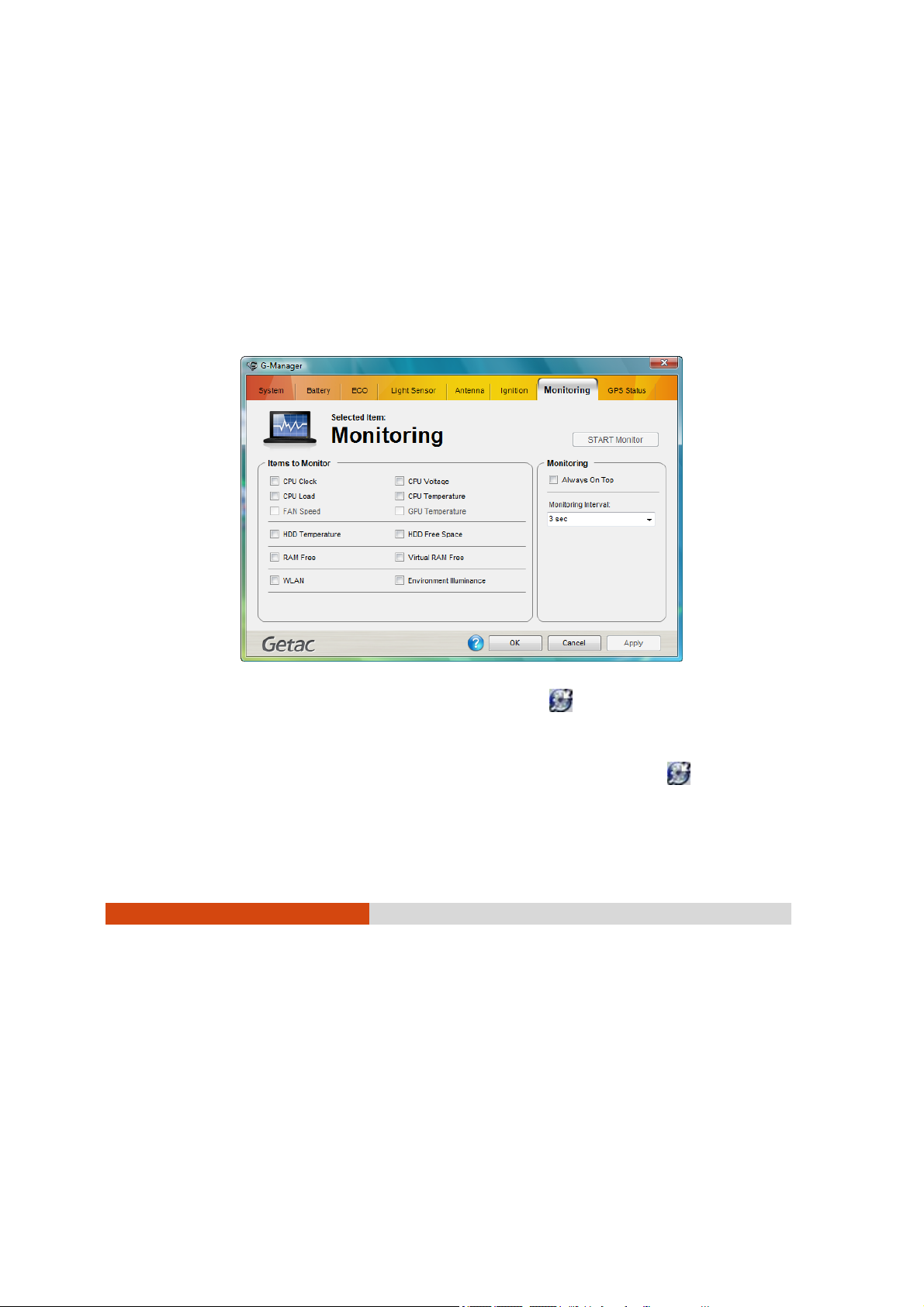
Monitoring Tab
The Monitoring tab allows you to select the items on your system to monitor.
Press OK and right-click on the G-manager icon (
system tray and click Start Monitor. The changes made to the monitoring
options are immediately implemented on the monitoring window.
To exit the monitor function, right-click on the G-manager icon (
located on the system tray and click Stop Monitor.
) located on the
)
Using Special Utilities 6-19
Page 94

Items to Monitor
The left portion of the Monitoring tab allows you to select which item to
monitor by selecting on the checkbox before each item. When enabled
the status of the selected Item is displayed and a live update is shown on
the screen. Items with higher priority are shown on top of items with lower
priority (see the next table).
Priority Monitoring Items Priority Monitoring Items
1 CPU clock 9 WLAN
2 CPU load 10 GPU temperature
3 CPU voltage 11 GMCH 1 temperature
4 CPU temperature 12 GMCH 2 temperature
5 RAM free 13 HDD temperature
6 Virtual RAM free 14 HDD free space
7 Battery left time 15 Fan speed
8 B attery left
percentage
16 Environment
luminance
Different model have different supported monitoring items;
non-supported items cannot be selected (gray out item).
Monitoring Options
The right portion of the Monitoring tab allows you to set how the
monitored items are displayed. The changes made to the monitoring
options are immediately implemented on the monitoring window.
z Always On Top – allows the monitoring window to remain on top of your
display.
z Background Color – select this option to display the color window for
selecting the background color. If the checkbox is not selected, the
background of the monitoring window is transparent.
6-20
Using Special Utilities
Page 95

z Monitoring Interval – allows you to set the frequency of updates on the
monitoring window (1/3/5/10/30 seconds, or 1/5/30 minutes, or 1 hour).
z Transparency – allows you to set the level of transparency of the
monitoring window (10 ~ 90 %).
Using Special Utilities 6-21
Page 96
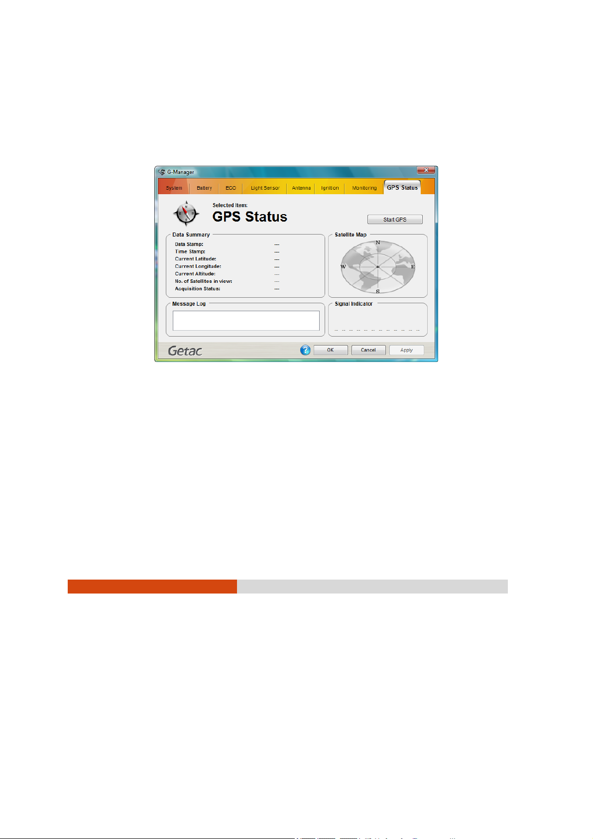
GPS Status Tab
The GPS Status tab shows the GPS signal availability status of the system’s
GPS module, allowing you to check if the GPS feature is working properly.
You may also need to install a third-party map of your particular location
(purchased separately).
Selected Item and Data Summary
The upper left portion of the GPS Status tab shows the various data (Date
Stamp, Time Stamp, Current Latitude, Current Longitude, Current Altitude,
No. of Satellites in View, and Acquisition Status) collected from satellites
and reflect any changes to the data.
Unlike the other items, Acquisition Status only shows whether GPS signal
acquisition is successful or not.
6-22
Using Special Utilities
Page 97

Message Log
The lower left portion of the GPS Status tab shows a summary of raw data
string received from satellites which can only be viewed but not editable.
The Message Log window is auto-scrollable and will be cleared as soon as
GPS signal is disconnected.
Satellite Map
The upper right portion of the GPS Status tab shows the satellites
discovered and are placed on the satellite map according to their
parsed latitude and longitude. Satellites in use are displayed in yellow color
with their PRN number while satellites in view but not in use are displayed
in blue color.
Signal Indicator
The lower right portion of the GPS Status tab shows the 12 satellites’ signal
indicator. The length of the green bar underneath each satellite changes
dynamically, the stronger the signal the longer the bar shown. Beneath
each signal bar is the PRN number of each discovered satellite (“00” is
shown when GPS module is not functioning or satellite was not
discovered).
Open/Close GPS
This button allows you to test the GPS module. Upon clicking on Open GPS,
the following three conditions may be shown:
z GPS module has successfully connected –
The button changes from “Opening . . . “ to “Close GPS.” The item
Acquisition Status under the Data Summary portion of the GPS Status
tab will change from “Inactive” to “Acquiring . . . “ and begin the
positioning process. It will then change to “Acquired” when GPS
module has successfully been positioned.
z GPS COM port is not available –
When other GPS program is running, a warning window pops-up and
Using Special Utilities 6-23
Page 98

displays the message “GPS COM port not available! Please close all
GPS program and try again.” to inform you to close the other GPS
program to free up the COM port. After closing the other GPS
program, click Open GPS button again to try.
z GPS COM port is somehow not functioning –
A warning window pops-up and displays the message “Time out
opening GPS COM port!” when GPS COM port is not responding after
5 seconds.
Upon clicking on Close GPS, the GPS COM port will be closed and the
button will change to show Open GPS. All information under the Satellite
Map, Signal Indicator, Message Log, and Data Summary portion of the
GPS Status tab is cleared except for the item Acquisition Status which will
show “Inactive.”
GPS connection will be automatically closed whenever G-Manager is
closed.
6-24
Using Special Utilities
Page 99

Chapter 7
Caring for the Tablet PC
Taking good care of your tablet PC will ensure a trouble-free operation
and reduce the risk of damage to your tablet PC.
This chapter gives you guidelines covering areas such as protecting,
storing, cleaning, and traveling.
Caring for the Tablet PC 7-1
Page 100

Protecting the Tablet PC
To safeguard the integrity of your tablet PC data as well as the tablet PC
itself, you can protect the tablet PC in several ways as described in this
section.
Using the Cable Lock
You can use a Kensington-type cable lock to protect your tablet PC
against theft. The cable lock is available in most tablet PC stores.
To use the lock, loop the lock cable around a stationary object such as a
table. Insert the lock to the Kensington lock hole and turn the key to
secure the lock. Store the key in a safe place.
7-2
Caring for the Tablet PC
 Loading...