

Page 1

UX10
USER MANUAL
Rugged Mobile Computing Solutions
Page 2

April 2019
TRADEMARKS
All brand and product names are trademarks or registered trademarks of
their respective companies.
NOTE
The information in this manual is subject to change without notice.
For the latest version of the manual, please visit the Getac website at
www.getac.com
.
Page 3

Table of Contents
Chapter 1
Chapter 2 Operating Your Tablet PC .............................................. 14
Chapter 3 Managing Power ............................................................ 23
Getting Started ................................................................. 1
Getting the Tablet PC Running ................................................. 2
Installing the Battery Pack .................................................... 2
Installing the Micro-SIM Card (Optional) ............................. 2
Connecting to AC Power ....................................................... 3
Turning On and Off the Tablet PC ....................................... 4
Identifying Hardware Components .......................................... 5
Front Components ................................................................. 5
Rear Components .................................................................. 8
Right-Side Components ....................................................... 10
Left-Side Components ......................................................... 10
Top Components.................................................................. 12
Navigating on the Screen ........................................................ 15
Using the Touchscreen ........................................................ 15
Using the Dual Mode Display (Optional) ........................... 18
Using Network and Wireless Connections ............................. 19
Using the LAN (Optional) .................................................... 19
Using the WLAN................................................................... 19
Using the Bluetooth Feature .............................................. 20
Using the WWAN Feature (Optional) ................................ 21
AC Adapter ............................................................................... 24
Battery Pack .............................................................................. 25
Charging the Battery Pack .................................................. 25
Initializing the Battery Pack ................................................ 26
Checking the Battery Level ................................................. 26
Battery Low Signals and Actions ........................................ 27
Replacing the Battery Pack ................................................. 28
i
Page 4

Hot Swapping the Battery Pack (Optional) ....................... 29
Power-Saving Tips .................................................................... 30
Appendix A Specifications ................................................................. 31
Appendix B Regulatory Information ................................................. 33
On the Use of the System ........................................................ 34
Class B Regulations .............................................................. 34
ANSI Warning ....................................................................... 35
Safety Notices ....................................................................... 36
On the Use of the RF Device.................................................... 39
USA and Canada Safety Requirements and Notices .......... 39
European Union CE Marking and Compliance Notices ..... 41
User Notification of Take-back Service ................................... 43
ENERGY STAR 7.0 ..................................................................... 44
Battery Recycling ...................................................................... 46
About Battery and External Enclosure Replacement ............ 47
Battery .................................................................................. 47
External Enclosure ............................................................... 47
ii
Page 5

Chapter 1
This chapter first tells you step by step how to get the Tablet PC up and
running. Then, you will find a section briefly introducing the external
components of the Tablet PC.
1
Page 6
Getting the Tablet PC Running
Installing the Battery Pack
1. With the battery pack correctly oriented, attach its connector side to the
battery compartment at an angle and then press down the other side.
The battery release latch should automatically engage.
2. Slide the lock of the battery release latch to the locked position.
CAUTION: Make sure the latch is correctly locked, not revealing the
underneath red part.
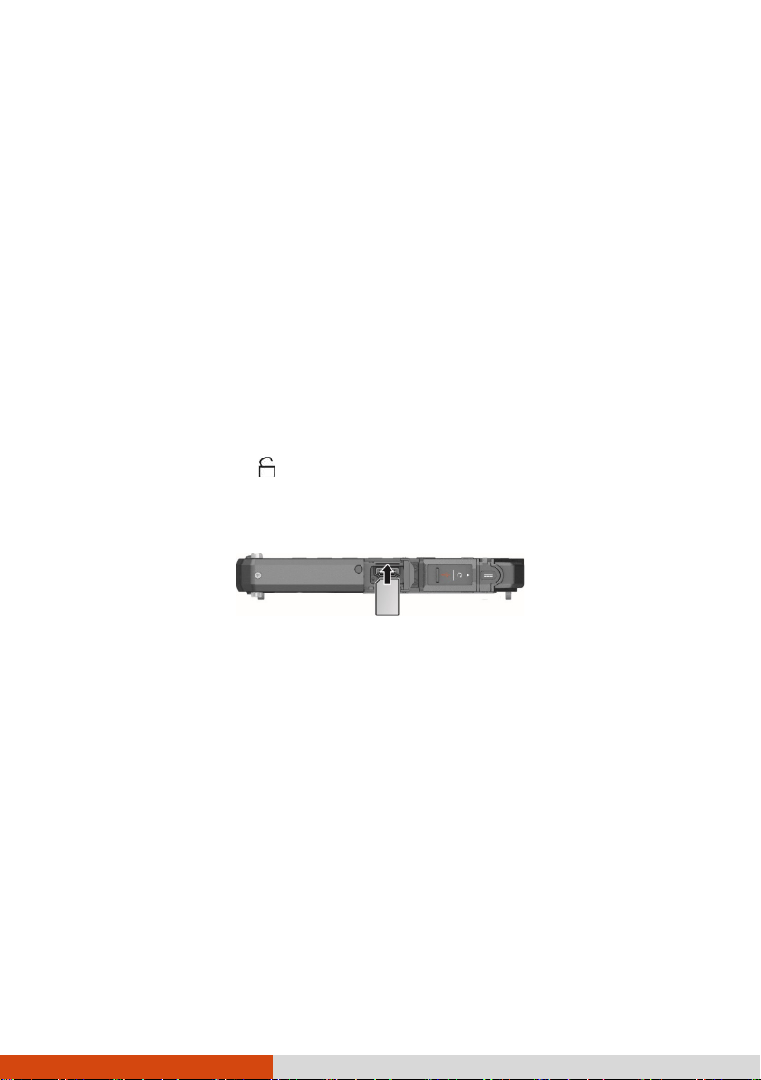
Installing the Micro-SIM Card (Optional)
1. Locate the micro-SIM card slot. Slide the protective cover to the
unlocked position ( ) and open the cover.
2. Noting the orientation, insert the micro-SIM card all the way into the
slot.
NOTE: To remove the micro-SIM card, just push in the card to release it and
then pull it out.
2
Page 7

Connecting to AC Power
CAUTION: Use only the AC adapter included with your Tablet PC. Using
other AC adapters may damage the Tablet PC.
NOTE:
The battery pack is shipped to you in power saving mode that protects it
from charging/discharging. It will get out of the mode to be ready for
use when you install the battery pack and connect AC power to the
Tablet PC for the very first time.
When the AC adapter is connected, it also charges the battery pack. For
information on using battery power, see Chapter 3.
You must use AC power when starting up the Tablet PC for the very first
time.
1. Open the cover of the power connector.
2. Plug the DC cord of the AC adapter to the power connector.
3. Plug the female end of the AC power cord to the AC adapter and the
male end to an electrical outlet.
4. Power is being supplied from the electrical outlet to the AC adapter and
onto your Tablet PC. Now, you are ready to turn on the Tablet PC.
3
Page 8
Turning On and Off the Tablet PC
Turning On
Press the power button ( ) for at least 2 seconds until the Power
Indicator lights up. The Windows operating system should start.
NOTE:
By default, there is 2-second delay time for the power button. You can
change the setting with the “Power Button Delay” item in the BIOS
Setup Utility.
Tapping the screen during startup may invoke a pre-boot menu (unless
the default settings have been changed). If the menu appears, simply
select Continue.
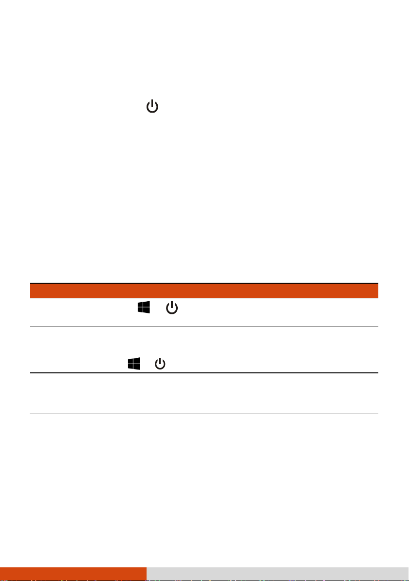
Turning Off
When you finish a working session, you can stop the system by turning off
the power or leaving it in Sleep or Hibernation mode:
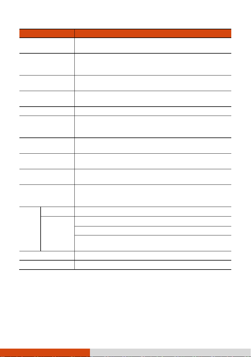
To... Do this...
Power off
(Shutdown)
Select Power Shut down.
Sleep Press the power button.*
-orTap Power Sleep.
Hibernate
* “Sleep” is the default result of the action. You can change what the
action does through Windows settings.
By default, this option is not shown in the Start menu. If
you want to use the feature, set up accordingly in Windows
settings.
4
Page 9
Identifying Hardware Components
NOTE: Depending on the model you purchased, the appearance of your
Tablet PC may not be exactly the same as those shown in this manual.
CAUTION: You need to open the protective covers to access the connectors.
When not using a connector, make sure to close the cover completely for
water- and dust-proof integrity. (Engage the locking mechanism if existing.)
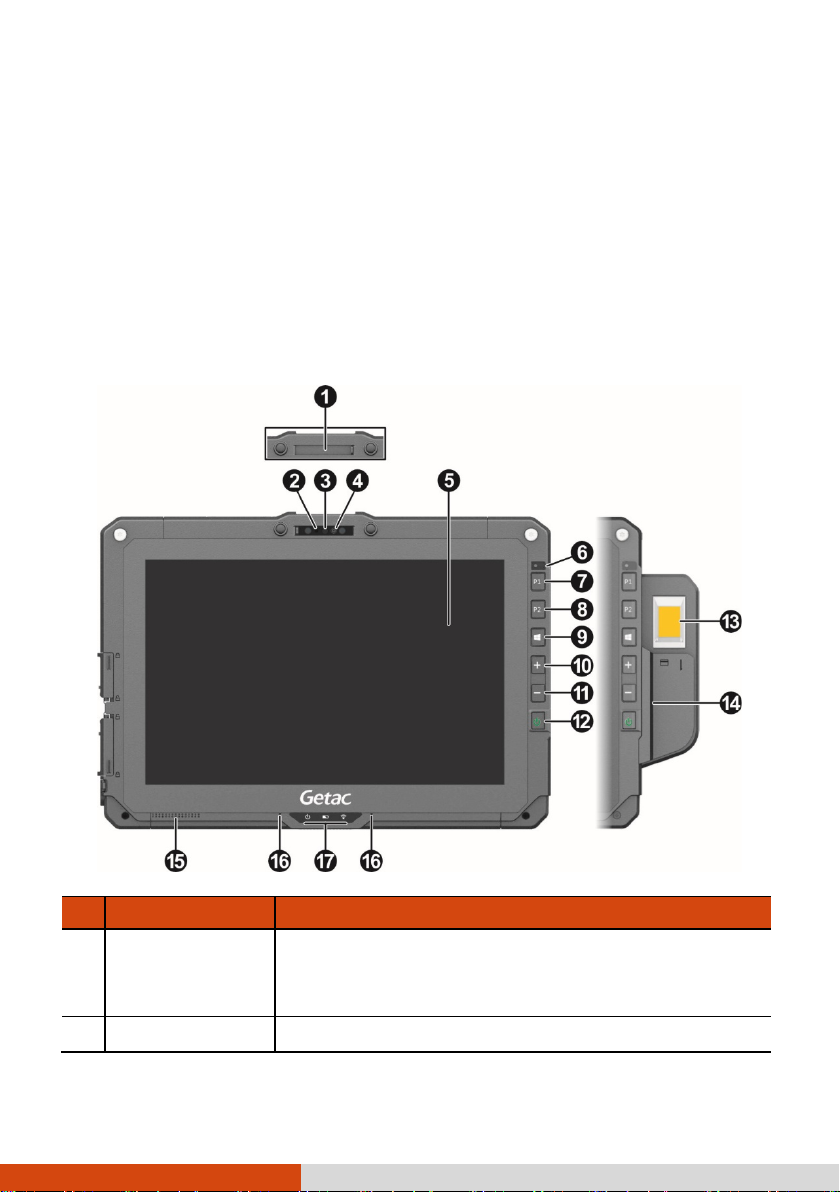
Front Components
Ref Component Description
Camera cover Covers the camera lens.
Slide the cover to open or close it. The cover
provides privacy protection.
Camera indicator Lights up when the camera is in use.
5
Page 10
arcode
Ref Component Description
IR sensor
(optional)
Camera lens Allows you to use the camera function.
Touchscreen Displays and receives information for the Tablet PC.
Detects the infrared energy of objects to form an
image. The sensor flashes red light when in use.
The near infrared (IR) imaging capability allows
you to use Windows Hello face authentication.
Light sensor
P1 button Opens or closes the OSD Control Panel.
P2 button
Windows logo
button
Plus button Increases the sound volume.
Minus button Decreases the sound volume.
Power button
Detects the surrounding lighting condition for
automatic adjustment of the LCD brightness.
When pressed longer:
Serves as the Ctrl+Alt+Del keyboard keys.
The default function is Camera or Barcode Trigger
depending on your model.
Camera Starts the G-Camera application.
B
Trigger
Opens or closes the Start menu.
Turns the power on or off. (The default “off” state
is “Sleep mode.”)
With a default setting of 2-second delay, you have
to press the button for at least 2 seconds for it to
function.
Serves as the trigger button for the
barcode reader if your model has the
module.
Fingerprint
scanner
(optional)
Magnetic Stripe
Reader
(optional)
Serves as the fingerprint verification, preventing
unauthorized access to your Tablet PC.
Reads magnetic stripe cards.
6
Page 11
Ref Component Description
Speaker Sends out sound and voice from your Tablet PC.
Microphone Receives sound and voice to record voice.
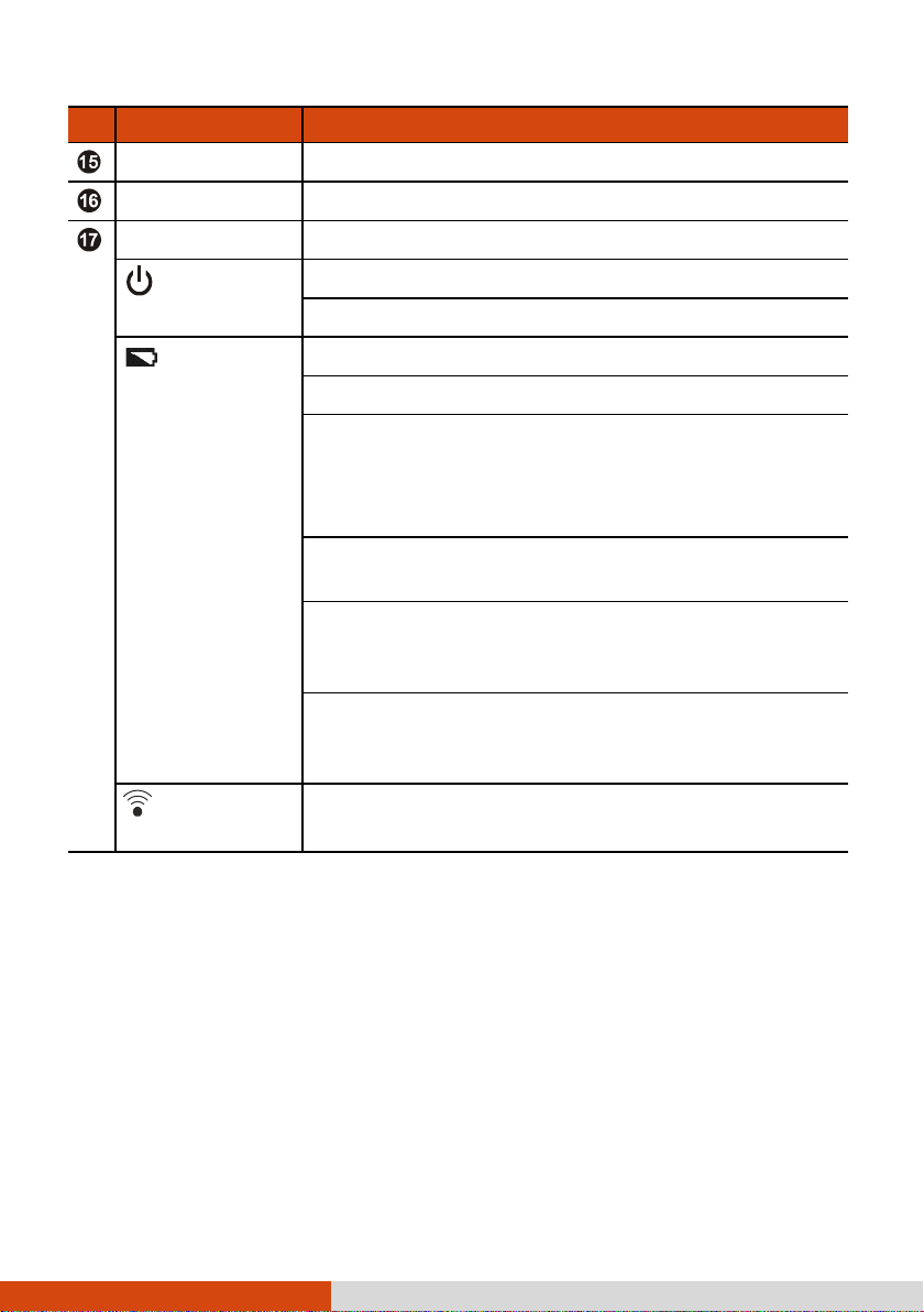
Indicators
Power
Battery Lights amber when the battery is being charged.
RF (Radio
Frequency)
NOTE: The hardware buttons (except the power button) can be re-defined
using G-Manager.
Lights blue when the power is on.
Blinks blue when the system is in Sleep mode.
Lights green when battery charging is completed.
Blinks green to indicate the battery’s built-in high
temperature protection mechanism is activated.
CAUTION: Do not remove the battery during this
period
Blinks red (once per second) when the battery’s
capacity is below 10%.
Blinks red rapidly (once per 0.5 second) when there
is a thermal protection problem. Ask for repair
service in case this happens.
Blinks amber when the battery charging is in an
abnormal state. Replace the battery in case this
happens.
Lights blue when the RF radio of any RF feature
(WLAN/Bluetooth/WWAN) is on.
7
Page 12
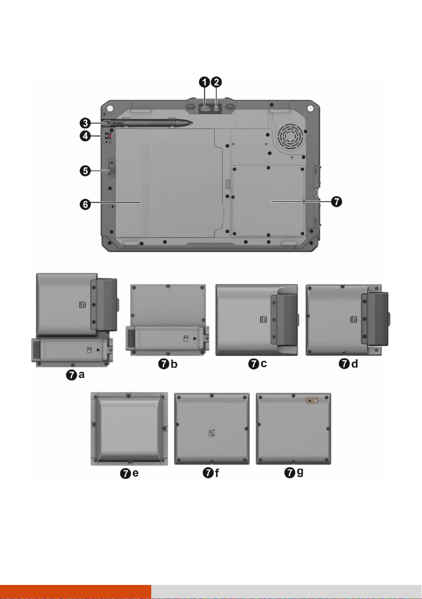
Rear Components
8
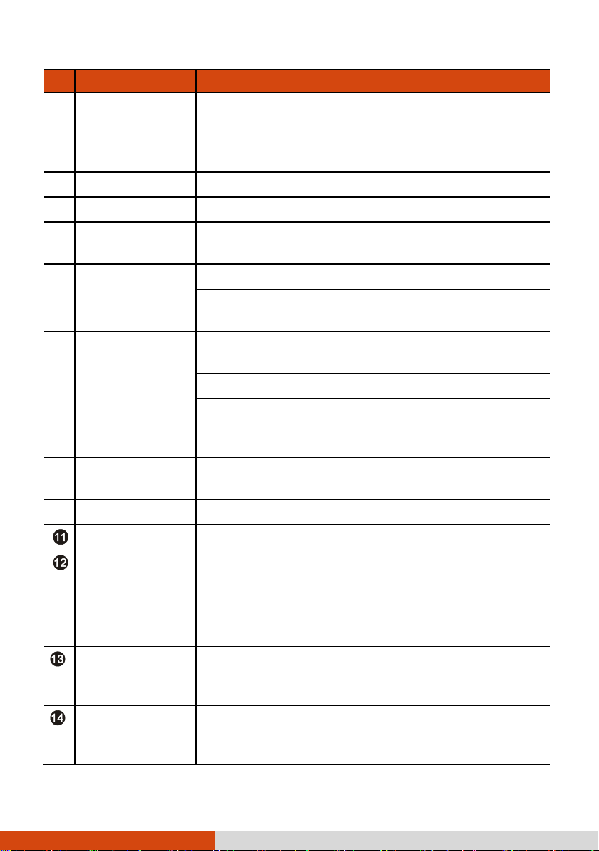
Page 13
eader and SSD
Ref Component Description
Flash Provides extra light when taking pictures.
Camera lens Allows you to use the camera function.
When the camera lens is in use, the indicator
beside it lights up.
Stylus holder Holds the stylus.
Security lock Locks the battery release latch.
Battery release
latch
Battery pack
Select models have one of the below components.
Smart card
a
r
module
b SSD module
Bridge battery
c
and smart card
reader module
Releases the battery pack.
Supplies power to your Tablet PC when external
power is not connected.
NOTE: If you have the high capacity battery
model, the battery pack looks different from the
one shown here.
Accepts a smart card for additional security
feature.
Contains the solid-state drive, which is the mass
storage device of your Tablet PC.
CAUTION: This device is not hot-swappable. Do
not remove it without turning off the system
first.
Contains the solid-state drive, which is the mass
storage device of your Tablet PC.
CAUTION: This device is not hot-swappable. Do
not remove it without turning off the system
first.
Provides enough extra power for the purpose of
hot swapping the battery pack.
Accepts a smart card for additional security
feature.
d
Smart card
reader module
Accepts a smart card for additional security
feature.
9
Page 14
Ref Component Description
UHF RFID
e
reader module
HID RFID
f
reader module
Reads data from UHF RFID tags.
Reads data from HID RFID tags.
Bridge battery
g
module
Provides enough extra power for the purpose of
hot swapping the battery pack.
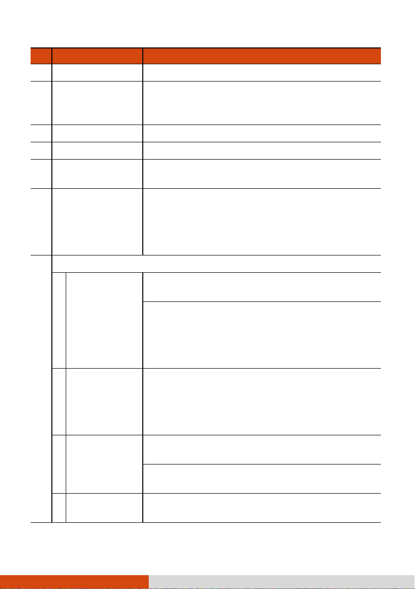
Right-Side Components
Ref Component Description
Kensington
lock
Locks the Tablet PC to a stationary object for
security.
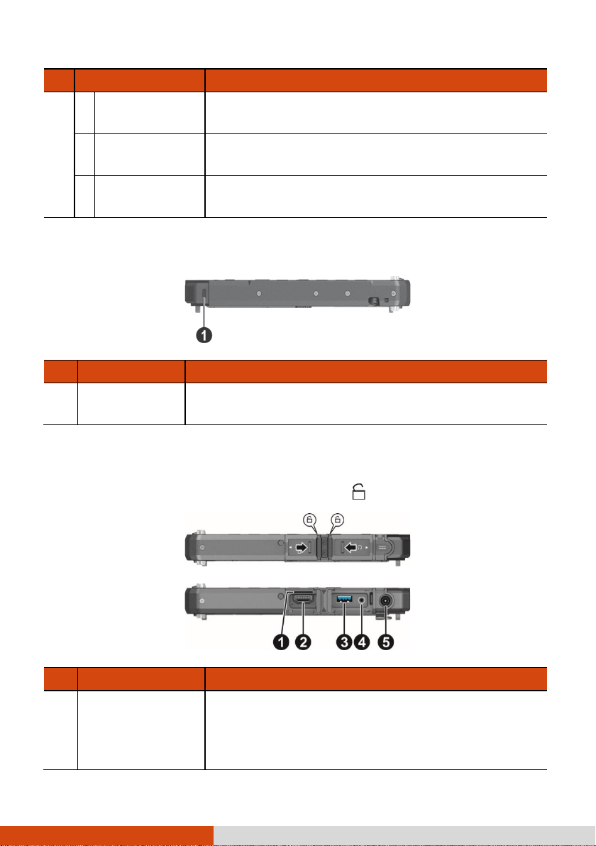
Left-Side Components
Slide the cover toward the unlocked position ( ) to open the cover.
Ref Component Description
Micro-SIM card
slot (optional)
Accepts a micro-SIM card for models having the
WWAN module.
NOTE: The slot still exists but cannot be used for
models without the WWAN module.
10
Page 15

Ref Component Description
HDMI connector Connects a HDMI monitor or TV set.
USB 3.1 port
Combo audio
connector
Power connector Connects the AC adapter.
Connects a USB device. This port supports Service
Diagnostic UART Mode.
Connects a set of headphones or external
speakers with amplifier.
Supports a headset microphone with 4-pole TRRS
3.5mm jack.
11
Page 16

Top Components
12
Page 17

Ref
Component Description
a None
Or can be one of the below components depending on your model:
Barcode reader
b
lens
c RFID reader Reads data from RFID tags.
d USB 3.0 port Connects a USB device.
USB 3.0 Type-C
e
port
RS232 serial
f
connector
g VGA connector
h RJ-45 connector Connects the LAN cable.
MicroSD card
i
slot
Scans and reads barcodes.
Connects a USB device that supports USB Type-C
connection.
Connects a serial device.
Connects an external display monitor.
Accepts a microSD card for removable storage
media.
Bottom Components
Ref Component Description
Docking
connectors
Tri antenna
passthrough
(optional)
Connects a proprietary dock such as the keyboard
dock, office dock, and vehicle dock.
Connects to the docking station for using external
GPS/WWAN/WLAN antenna.
13
Page 18

Chapter 2
Tablet PC
This chapter provides information about the use of the Tablet PC.
If you are new to computers, reading this chapter will help you learn the
operating basics. If you are already a computer user, you may choose to
read only the parts containing information unique to your Tablet PC.
CAUTION:
Do not expose your skin to the Tablet PC when operating it in a very hot
or cold environment.
The Tablet PC can get uncomfortably warm when you use it in high
temperatures. As a safety precaution in such a circumstance, do not
place the Tablet PC on your lap or touch it with your bare hands for
extended periods of time. Prolonged body contact can cause discomfort
and potentially a burn.
14
Page 19

Select this if you are using the
s
supplied with your model.)
Select this if you are wearing gloves
(
not
Select this if you prefer using
fingertips.
when raindrops are falling
on the screen and should be
rejected as input.
Navigating on the Screen
The screen of your Tablet PC is touch-sensitive. You can operate the Tablet PC
by touching the screen with your finger or the stylus.
CAUTION: Do not use a sharp object such as a ballpoint pen or pencil on the
touchscreen. Doing so may damage the touchscreen surface.
NOTE: An optical film has been attached to the screen before shipment. The
film is a consumable, which will be worn out by possible scratches. You can
purchase a new one when replacement is required.
Using the Touchscreen
Your Tablet PC has a capacitive touchscreen. This type of touchscreen
responds to objects that have conductive properties, such as fingertips and a
capacitive-tipped stylus.
You can change the touchscreen sensitivity settings to suit your scenario.
Double-tap the Touch Screen Mode shortcut on Windows desktop to open
the settings menu and select one of the options (as shown below).
Also, select this
NOTE:
In high temperatures (above 60
of Glove or Pen mode.
If liquid is spilled on the touchscreen causing a wet area, the area will stop
responding to any inputs. For the area to function again, you must dry it.
tylus. (You must use the one
referring to warm gloves or work gloves,
referring to touchscreen-capable gloves).
o
C / 140 °F), set the mode to Touch instead
15
Page 20

The following table shows how you use the touchscreen to obtain
equivalent mouse functions.
Term/Action
Tap: Touch the screen once. Click/Point
Double-tap: Touch the screen twice rapidly. Double-click
Tap and hold: Tap and hold until a popup menu appears. Right-click
Drag: Hold the stylus (or finger) on the screen and drag
across the screen until reaching your destination.
Equivalent
Mouse Function
Drag
Using Multi-touch Gestures
You can interact with your Tablet PC by placing two fingers on the screen.
The movement of the fingers across the screen creates “gestures,” which
send commands to the Tablet PC.
Here are the multi-touch gestures that you can use:
Gestures
Pan
(Scroll)
( = finger down; = finger up)
Actions
Descriptions
Use panning to see
another part of a page
that has scroll bars.
Zoom
(Pinch)
or
Drag 1 or 2 fingers up or down.
Move two fingers apart/toward each
other.
16
Use zooming to make
an item (a photo for
example) on the screen
larger or smaller. The
gesture works in
applications that
support mouse wheel
zooming.
Page 21

Gestures
Rotate
Press and
Tap
Twofinger Tap
Actions
( = finger down; = finger up)
or
Move two fingers in opposing
directions.
-orUse one finger to pivot around
another.
Press on target and tap using a
second finger.
Descriptions
Use rotating to move a
picture or other item
on the screen in a
circular direction
(clockwise or counterclockwise). The gesture
works in applications
that support the
specific gesture.
Use press and tap to
access the shortcut
menu.
The function is defined
by applications that
support the specific
gesture.
Flicks
Tap two fingers at the same time
(where the target is in the midpoint
between the fingers).
Make quick drag gestures in the
desired direction.
17
Flick left or right to
navigate back and
forward in a browser
and other applications.
The gesture works in
most applications that
support back and
forward.
Page 22

Using the Dual Mode Display (Optional)
Dual mode display (if your model has the feature) incorporates both
touchscreen and digitizer functions.
The display is set to Touchscreen mode by default. Touchscreen mode
provides all the functionalities that an ordinary touchscreen has. When the
Tablet PC receives signals from the digitizer pen, the display automatically
switches to Digitizer mode.
You can move the cursor by bringing the digitizer pen close to the screen,
without actually touching the screen’s surface.
18
Page 23

Using Network and Wireless
Connections
Using the LAN (Optional)
Select models have the LAN module. To connect the network cable to the
LAN module, connect one end of the LAN cable to the RJ-45 connector on
the Tablet PC and the other end to the network hub.
Using the WLAN
The WLAN (Wireless Local Area Network) module of your Tablet PC supports
IEEE 802.11a/b/g/n/ac.
Turning On/Off the WLAN Radio
To turn on the WLAN radio:
Select Settings Network & Internet Wi-Fi. Slide the Wi-Fi switch
to the On position.
To turn off the WLAN radio:
You can turn off the WLAN radio the same way you turn it on.
If you want to quickly turn off all wireless radio, simply switch on Airplane
mode. You can control the Airplane mode using one of the below methods.
Select Settings Network & Internet Airplane mode.
Use the Airplane Mode button in the OSD Control Panel.
19
Page 24

Connecting to a WLAN Network
1. Make sure that the WLAN function is enabled (as described above).
2. Select the network icon in the lower right of the task bar.
3. Select the device you want to connect from the search results.
4. Some networks require a network security key or passphrase. To connect
to one of those networks, ask your network administrator or Internet
service provider (ISP) for the security key or passphrase.
For more information on setting a wireless network connection, refer to
Windows online help.
Using the Bluetooth Feature
The Bluetooth technology allows short-range wireless communications
between devices without requiring a cable connection. Data can be
transmitted through walls, pockets and briefcases as long as two devices are
within range.
Turning On/Off the Bluetooth Radio
To turn on the Bluetooth radio:
Select Settings Devices Bluetooth. Slide the Bluetooth switch to
the On position.
To turn off the Bluetooth radio:
You can turn off the Bluetooth radio the same way you turn it on.
If you want to quickly turn off all wireless radio, simply switch on Airplane
mode. You can control the Airplane mode using one of the below methods.
Select Settings Network & Internet Airplane mode.
Use the Airplane Mode button in the OSD Control Panel.
Connecting to another Bluetooth Device
1. Make sure that the Bluetooth function is enabled (as described above).
20
Page 25

2. Make sure that the target Bluetooth device is turned on, discoverable
and within close range. (See the documentation that came with the
Bluetooth device.)
3. Select Settings Devices Bluetooth.
4. Select the device you want to connect from the search results.
5. Depending on the type of Bluetooth device that you want to connect
to, you will need to enter the pertinent information.
For detailed information on using the Bluetooth feature, see Windows’
online Help.
Using the WWAN Feature (Optional)
A WWAN (Wireless Wide Area Network) uses mobile telecommunication
cellular network technologies to transfer data. The WWAN module of your
Tablet PC supports 3G and 4G LTE.
NOTE:
Your model only supports data transmission. Voice transmission is not
supported.
For instructions on installing the micro-SIM card, see “Installing the
Micro-SIM Card (Optional)” in Chapter 1.
Turning On/Off the WWAN Radio
To turn on the WWAN radio:
Select Settings Network & Internet Airplane mode. Slide the
Cellular switch to the On position.
To turn off the WWAN radio:
You can turn off the WWAN radio the same way you turn it on.
If you want to quickly turn off all wireless radio, simply switch on Airplane
mode. You can control the Airplane mode using one of the below methods.
Select Settings Network & Internet Airplane mode.
Use the Airplane Mode button in the OSD Control Panel.
21
Page 26

Setting up a WWAN Connection
Tap Settings Network & Internet Cellular. (For detailed
information on cellular settings in Windows 10, see Microsoft Support
website.)
22
Page 27

Chapter 3
Your Tablet PC operates either on external AC power or on internal battery
power.
This chapter tells you how you can effectively manage power. To maintain
optimal battery performance, it is important that you use the battery in the
proper way.
23
Page 28

AC Adapter
CAUTION:
The AC adapter is designed for use with your Tablet PC only. Connecting
the AC adapter to another device can damage the adapter.
The AC power cord supplied with your Tablet PC is for use in the country
where you purchased your Tablet PC. If you plan to go overseas with the
Tablet PC, consult your dealer for the appropriate power cord.
When you disconnect the AC adapter, disconnect from the electrical outlet
first and then from the Tablet PC. A reverse procedure may damage the
AC adapter or Tablet PC.
When unplugging the connector, always hold the plug head. Never pull
on the cord.
The AC adapter serves as a converter from AC (Alternating Current) to DC
(Direct Current) power because your Tablet PC runs on DC power, but an
electrical outlet usually provides AC power. It also charges the battery pack
when connected to AC power.
The adapter operates on any voltage in the range of 100~240 V AC.
24
Page 29

Battery Pack
The battery pack is the internal power source for the Tablet PC. It is
rechargeable using the AC adapter.
NOTE: Care and maintenance information for the battery is provided in the
“Battery Pack Guidelines” section in Chapter 7.
Charging the Battery Pack
NOTE:
Charging will not start if the battery’s temperature is outside the allowed
range, which is between 0 °C (32 °F) and 50 °C (122 °F). Once the
temperature meets the requirements, charging automatically resumes.
During charging, do not disconnect the AC adapter before the battery
has been fully charged; otherwise you will get a prematurely charged
battery.
The battery has a high temperature protection mechanism which limits
the maximum charge of the battery to 80% of its total capacity in the
event of high temperature conditions. In such conditions, the battery
will be regarded as fully charged at 80% capacity.
The battery level may automatically lessen due to the self-discharge
process, even when the battery pack is fully charged. This happens no
matter if the battery pack is installed in the Tablet PC.
To charge the battery pack, connect the AC adapter to the Tablet PC and an
electrical outlet. The Battery Indicator ( ) on the Tablet PC glows amber
to indicate that charging is in progress. You are advised to keep the Tablet
PC power off while the battery is being charged. When the battery is fully
charged, the Battery Charge Indicator glows green.
The charging time is approximately 3 hours (for the standard battery pack)
and 5.5 hours (for the high capacity battery pack) when the power is off.
CAUTION: After the Tablet PC has been fully recharged, do not immediately
disconnect and reconnect the AC adapter to charge it again. Doing so may
damage the battery.
25
Page 30

Initializing the Battery Pack
You need to initialize a new battery pack before using it for the first time or
when the actual operating time of a battery pack is much less than
expected. Initializing is the process of fully charging, discharging, and then
charging. It can take several hours.
The G-Manager program provides a tool called “Battery Recalibration” for
the purpose.
Checking the Battery Level
NOTE: Any battery level indication is an estimated result. The actual
operating time can be different from the estimated time, depending on
how you are using the Tablet PC.
The operating time of a fully charged battery pack depends on how you are
using the Tablet PC. When your applications often access peripherals, you
will experience a shorter operating time.
By Operating System
You can check the approximate battery level using the battery meter function
of the operating system. To read the battery level in Windows, click the
battery icon on the taskbar.
By Gas Gauge
On the exterior side of the battery pack is a gas gauge for displaying the
estimated battery charge.
When the battery pack is not installed in the Tablet PC and you want to
know the battery charge, you can press the push-button to see the number
of LEDs that light up. Each LED represents 20% charge.
26
Page 31

level. By default, Windows will display a notification
Battery Low Signals and Actions
The battery icon changes appearance to display the current state of the
battery.
Battery
Icon
When the battery is low, the Tablet PC’s Battery Indicator ( ) also blinks
red to alert you to take actions.
Always respond to low-battery by connecting the AC adapter, placing your
Tablet PC in Hibernation mode, or turning off the Tablet PC.
Battery
Discharging
Low
Critically
low
Level
Description
The icon shows the charge remaining in 10-percent
increments until the charge reaches the low-battery
level.
The battery charge has reached the low-battery
level.
The battery charge has reached the critical battery
and put your Tablet PC into Hibernation.
27
Page 32

Replacing the Battery Pack
CAUTION:
There is danger of explosion if the battery is incorrectly replaced.
Replace the battery only with the Tablet PC manufacturer’s battery
packs. Discard used batteries according to the dealer’s instructions.
Do not attempt to disassemble the battery pack.
NOTE:
You can hot swap the battery pack if your model has the bridge battery.
If you have the high capacity battery model, the battery pack looks
different from the one shown here. The removal and installation
method is the same.
To replace the battery pack, follow these steps:
1. Turn off the Tablet PC and disconnect the AC adapter.
Skip this step if you are hot swapping the battery pack. (See “Hot
Swapping the Battery Pack (Optional)” for more information.)
2. Slide the lock of the battery release latch to the unlocked position.
3. Slide the battery release latch. The battery pack will slightly pop up.
Remove the battery pack from its compartment.
4. Fit another battery pack into place. With the battery pack correctly
oriented, attach its connector side to the battery compartment at an
angle and then press down the other side). The battery release latch
should automatically engage.
5. Slide the lock of the battery release latch to the locked position.
CAUTION: Make sure the latch is correctly locked, not revealing the
underneath red part.
28
Page 33

Hot Swapping the Battery Pack (Optional)
If your model has the bridge battery, you can hot swap the battery pack.
“Hot swapping” means you can safely replace the battery pack without
shutting down while your Tablet PC is running on battery power.
Hints and Reminders
See “Replacing the Battery Pack” for replacement instructions and note the
following hints and reminders on hot swapping:
Make sure the battery pack to be installed is charged.
The appropriate temperature range for hot swapping the battery pack
is between -21°C (-5.8 °F) and 55 °C (131 °F).
Check the Battery Hot Swapping Indicator after removing a battery
pack. Replace the battery pack only when the indicator lights in green.
A red light means there is not enough extra power for you to safely hot
swap the battery pack.
Once a battery pack is removed, the display brightness level will be fixed
at a low level and cannot be adjusted.
If a charged battery pack is not inserted within 2 minutes, the Battery
Hot Swapping Indicator blinks in red and the Tablet PC enters
Hibernation mode.
After removing the battery pack, do not connect and immediately
disconnect the AC adapter. This will shut down the Tablet PC.
About the Bridge Battery
The bridge battery is not user-replaceable and is invisible to the operating
system. It never functions as the power source as long as the battery
pack is installed.
The bridge battery is charged by external AC power if the AC adapter is
connected.
If the Battery Hot Swapping Indicator blinks in amber, it means the
bridge battery charging is in an abnormal state. Replace the bridge
battery in case this happens.
29
Page 34

Power-Saving Tips
Aside from enabling your Tablet PC’s power saving mode, you can do your
part to maximize the battery’s operating time by following these
suggestions.
Do not disable Power Management.
Decrease the LCD brightness to the lowest comfortable level.
Shorten the length of time before Windows turn off the display.
When not using a connected device, disconnect it.
Turn off the wireless radio if you are not using the wireless module
(such as WLAN, Bluetooth, or WWAN).
Turn off the Tablet PC when you are not using it.
30
Page 35

Appendix A
NOTE: Specifications are subject to change without any prior notice.
Parts Specifications
CPU - Intel® Core™ i7-8665U Qual Core, 1.9GHz up to 4.8GHz,
8MB Intel® Smart Cache
- Intel® Core™ i7-8565U Qual Core, 1.8GHz up to 4.6GHz,
8MB Intel® Smart Cache
- Intel® Core™ i5-8365U Qual Core, 1.6GHz up to 4.1GHz,
6MB Intel® Smart Cache
- Intel® Core™ i5-8265U Qual Core, 1.6GHz up to 3.9GHz,
6MB Intel® Smart Cache
- Intel® Core™ i3-8145U Dual Core, 2.1GHz up to 3.9GHz,
4MB Intel® Smart Cache
BIOS Insyde, Flash EEPROM, 32MB, UEFI, supporting ACPI, TPM,
Computrace, AMT12, WMI, BIOS diagnostic, and Service
Diagnostic UART Mode
RAM 4/8/16GB DDR4, 2400MHz
Video Controller UMA - Intel UHD Graphics 620 (GT2)
Display
Panel
Touchscreen Capacitive multi-touch screen - 10 point
Audio Features Azalia, High Definition audio
Speaker 85db @ 30cm
Microphone Integrated x 2
Mass storage device 128GB/256GB/512GB SSD (Solid-State Disk), SATA3 and PCIe
Card slots MicroSD (option)
10.1-inch (16:9) TFT LCD with PSR (Panel Self Refresh), FHD
1920 x 1200, dimmer mode, blackout mode, sunlight
readable, 1000 nits standard brightness
Gen3x4 interface available
Smart Card (option)
31
Page 36
Note:
3G _ WCDMA 900/1800/2100
4G _ LTE 900/LTE 1800/LTE 2100/LTE 2600
Parts Specifications
I/O ports USB 3.1, HDMI, combo audio (4-pole TRRS 3.5mm type),
Docking, tri antenna passthrough (option)
Option I/O
(mutually exclusive)
LAN (option) Intel® i219-LM Gigabit Network Connection, 10/100/1000
Wireless LAN +
Bluetooth
WWAN (option) Sierra EM7455/EM7511/EM7565, 3G/4G LTE
GPS (option) Internal UART
Camera Front: FHD 2MP webcam, IR sensor (option)
Barcode reader
(option)
Contactless smart
card reader (option)
Security Kensington lock
Power AC adapter
Battery pack Standard: Lithium-ion Prismatic type, 6-cell
Dimension (LxW×D) 275 x 191 x 22.4 mm (10.83 × 7.52 × 0.88 inches)
Weight 1.22 kg (2.69 lbs.)
One of the below on the top side:
Barcode reader / NFC/RFID reader / USB 3.0 / USB 3.0 Type-C /
RS232 serial / VGA /RJ-45 / MicroSD card slot
Mbps Ethernet
Intel 9260NGW 2x2 802.11 AC + Bluetooth 5.0 combo
Optional descrete GPS: MC1010
Optional descrete GPS/GLONASS MT5110G
Rear: 8M pixel, autofocus, LED, video capture
1D and 2D
LF/HF/UHF available
TPM 2.0
Fingerprint scanner (option)
Universal 65 W; input: 100∼240 V, 50/60 Hz; output: 19V
High capacity: Lithium-ion cylindrical type, 9-cell
Bridge battery (option): Lithium-ion Prismatic type, 2-cell
Hot Swap technology
32
Page 37

Appendix B
Information
This appendix provides regulatory statements and safety notices on your
Tablet PC.
NOTE: Marking labels located on the exterior of your Tablet PC indicate the
regulations that your model complies with. Please check the marking labels
and refer to the corresponding statements in this appendix. Some notices
apply to specific models only.
33
Page 38

On the Use of the System
Class B Regulations
USA
Federal Communications Commission Radio Frequency Interference
Statement
NOTE:
This equipment has been tested and found to comply with the limits for a
Class B digital device pursuant to Part 15 of the FCC Rules. These limits are
designed to provide reasonable protection against harmful interference in a
residential installation. This equipment generates, uses, and can radiate
radio frequency energy and, if not installed and used in accordance with the
instructions, may cause harmful interference to radio communications.
However, there is no guarantee that interference will not occur in a particular
installation. If this equipment does cause harmful interference to radio or
television reception, which can be determined by turning the equipment off
and on, the user is encouraged to try to correct the interference by one or
more of the following measures:
Reorient or relocate the receiving antenna.
Increase the separation between the equipment and receiver.
Connect the equipment into an outlet on a circuit different from that to
which the receiver is connected.
Consult the dealer or an experienced radio/TV technician for help.
Any changes or modifications not expressly approved by the manufacturer
could void the user’s authority to operate the equipment.
Please note:
The use of a non-shielded interface cable with this equipment is prohibited.
Company name: Getac USA
Address: 15495 Sand Canyon Rd., Suite 350 Irvine, CA 92618 USA
Phone: 949-681-2900
34
Page 39

Canada
Canadian Department of Communications
Radio Interference Regulations Class B Compliance Notice
This Class B digital apparatus meets all requirements of the Canada
Interference-Causing equipment regulations.
Cet appareil numérique de Classe B respecte toutes les exigences du
Règlement Canadien sur le matériel brouileur.
This digital apparatus does not exceed the Class B limits for radio noise
emissions from digital apparatus set out in the Radio Interference
Regulations of the Canadian Department of Communications.
Le présent appareil numérique n’émet pas de bruits radioélectriques
dépassant les limites applicables aux appareils numériques de la classe B
prescrites dans le Règlement sur le brouillage radioélectrique édicté par le
ministère des Communications du Canada.
ANSI Warning
Equipment approved for ANSI/ISA 12.12.01, Nonincendive Electrical
Equipment for use in Class 1, Division 2, Group A, B, C, and D.
Maximum ambient temperature: 40°C
WARNING: To prevent ignition of a hazardous atmosphere, batteries
must only be changed or charged in an area known to be nonhazardous.
EXPLOSION HARZARD WARNING: External connections/hubs through the
connectors as mentioned (USB connector, Ethernet connector, phone
connector, video port, serial port, power supply connector, microphone
jack, headphones jack, and buttons/switches) and super multi
DVD/combo drive are not to be used in a hazardous location.
Power adapter shall not be used in hazardous locations.
35
Page 40

Safety Notices
About the Battery
If the battery is mishandled, it may cause fire, smoke or an explosion and
the battery’s functionality will be seriously damaged. The safety instructions
listed below must be followed.
Danger
Do not immerse the battery with liquid such as water, sea water or soda.
Do not charge/discharge or place the battery in high-temperature (more
than 80 °C / 176 °F) locations, such as near a fire, heater, in a car in direct
sunlight, etc.
Do not use unauthorized chargers.
Do not force a reverse-charge or a reverse-connection.
Do not connect the battery with AC plug (outlet) or car plugs.
Do not adapt the battery to unspecified applications.
Do not short circuit the battery.
Do not drop or subject the battery to impacts.
Do not penetrate with a nail or strike with a hammer.
Do not directly solder the battery.
Do not disassemble the battery.
Warning
Keep the battery away from infants.
Stop using the battery if there are noticeable abnormalities such as
abnormal smell, heat, deformities, or discoloration.
Stop charging if the charging process cannot be finished.
In case of a leaking battery, keep the battery away from flames and do
not touch it.
Pack the battery tightly during transport.
36
Page 41

Caution
Do not use the battery where static electricity (more than 100V) exists
that might damage the protection circuit of the battery.
When children are using the system, parents or adults must ensure that
they are using the system and battery correctly.
Keep the battery away from flammable materials during charging and
discharging.
In case lead wires or metal objects come out from the battery, you must
seal and insulate them completely.
Caution Texts Concerning Lithium Batteries
DANISH
ADVARSEL! Lithiumbatteri – Eksplosionsfare ved fejlagtig håndtering.
Udskiftning må kun ske med batteri af samme fabrikat og type. Levér det
brugte batteri tilbage til leverandøren.
NORWEGIAN
ADVARSEL: Eksplosjonsfare ved feilaktig skifte av batteri. Benytt samme
batteritype eller en tilsvarende type anbefalt av apparatfabrikanten. Brukte
batterier kasseres i henhold til fabrikantens instruksjoner.
SWEDISH
VARNING: Explosionsfara vid felaktigt batteribyte. Använd samma
batterityp eller en ekvivalent typ som rekommenderas av
apparattillverkaren. Kassera använt batteri enligt fabrikantens instruktion.
FINNISH
VAROITUS: Paristo voi räjähtää, jos se on virheellisesti asennettu. Vaihda
paristo ainoastaan valmistajan suosittelemaan tyyppiin. Hävitä käytetty
paristo valmistajan ohjeiden mukaisesti.
ENGLISH
CAUTION: Danger of explosion if battery is incorrectly replaced. Replace
only with the same or equivalent type recommended by the equipment
manufacturer. Discard used batteries according to manufacturer‘s
instructions.
DEUTSCH
VORSICHT: Explosionsgefahr bei unsachgemäßem Austausch der Batterie.
Ersatz nur durch denselben oder einen vom Hersteller empfohlenen gleich-
37
Page 42

wertigen Typ. Entsorgung gebrauchter Batterien nach Angaben des
Herstellers.
FRENCH
ATTENTION: II y a danger d’explosion s’il y a remplacement incorrect de la
batterie. Remplacer uniquement avec une batterie du même type ou d’un
type équivalent recommandé par le constructeur. Mettre au rebut les
batteries usagées conformément aux instructions du fabricant.
Attention (for USA Users)
The product that you have purchased contains a rechargeable battery. The
battery is recyclable. At the end of its useful life, under various state and
local laws, it may be illegal to dispose of this battery into the municipal
waste stream. Check with your local solid waste officials for details in your
area for recycling options or proper disposal.
About the AC Adapter
Use only the AC adapter supplied with your Tablet PC. Use of another
type of AC adapter will result in malfunction and/or danger.
Do not use the adapter in a high moisture environment. Never touch
the adapter when your hands or feet are wet.
Allow adequate ventilation around the adapter when using it to
operate the device or charge the battery. Do not cover the AC adapter
with paper or other objects that will reduce cooling. Do not use the AC
adapter while it is inside a carrying case.
Connect the adapter to a proper power source. The voltage
requirements are found on the product case and/or packaging.
Do not use the adapter if the cord becomes damaged.
Do not attempt to service the unit. There are no serviceable parts inside.
Replace the unit if it is damaged or exposed to excess moisture.
38
Page 43

On the Use of the RF Device
USA and Canada Safety Requirements and
Notices
IMPORTANT NOTE: To comply with FCC RF exposure compliance requirements,
the antenna used for this transmitter must not be co-located or operating in
conjunction with any other antenna or transmitter.
Radio Frequency Interference Requirements and SAR
This device meets the government’s requirements for exposure to radio
waves.
This device is designed and manufactured not to exceed the emission limits
for exposure to radio frequency (RF) energy set by the Federal
Communications Commission of the U.S. Government.
This device complies with FCC radiation exposure limits set forth for an
uncontrolled environment.
EMC Requirements
This device uses, generates and radiates radio frequency energy. The radio
frequency energy produced by this device is well below the maximum
exposure allowed by the Federal Communications Commission (FCC).
This device complies with Part 15 of the FCC Rules. Operation is subject to
the following two conditions:
(1) This device may not cause harmful interference.
(2) This device must accept any interference received, including interference
that may cause undesired operation.
The FCC limits are designed to provide reasonable protection against
harmful interference when the equipment is installed and used in
accordance with the instruction manual and operated in a commercial
environment. However, there is no guarantee that interference will not
occur in a particular commercial installation, or if operated in a residential
area.
If harmful interference with radio or television reception occurs when the
device is turned on, the user must correct the situation at the user’s own
39
Page 44

expense. The user is encouraged to try one or more of the following
corrective measures:
Reorient or relocate the receiving antenna.
Increase the separation between the equipment and receiver.
Connect the equipment into an outlet on a circuit different from that to
which the receiver is connected.
Consult the dealer or an experienced radio/TV technician for help.
CAUTION: The Part 15 radio device operates on a non-interference basis
with other devices operating at this frequency. Any changes or modification
to said product not expressly approved by the manufacturer could void the
user’s authority to operate this device.
Canada Radio Frequency Interference Requirements
To prevent radio interference to the licensed service, this device is intended
to be operated indoors and away from windows to provide maximum
shielding. Equipment (or its transmit antenna) that is installed outdoors is
subject to licensing.
Pour empêcher que cet appareil cause du brouillage au service faisant l'objet
d'une licence, il doit être utilisé à l'intérieur et devrait être placé loin des
fenêtres afin de fournir un écran de blindage maximal. Si le matériel (ou son
antenne d'émission) est installé à l'extérieur, il doit faire l'objet d'une
licence.
NCC Note:
Administrative Regulations on Low Power Radio Waves Radiated Devices warning:
Article 12-Without permission granted by the NCC, any company, enterprise, or user is
not allowed to change frequency, enhance transmitting power or alter original
characteristic as well as performance to a approved low power radio-frequency devices.
Article 14-The low power radio-frequency devices shall not influence aircraft security
and interfere legal communications; If found, the user shall cease operating immediately
until no interference is achieved.
The said legal communications means radio communications is operated in compliance
with the Telecommunications Act.
The low power radio-frequency devices must be susceptible with the interference from
legal communications or ISM radio wave radiated devices.
40
Page 45

European Union CE Marking and
Compliance Notices
Statements of Compliance
English
This product follows the provisions of the European Directive 2014/53/EU.
Danish
Dette produkt er i overensstemmelse med det europæiske direktiv 2014/53/EU.
Dutch
Dit product is in navolging van de bepalingen van Europees Directief
2014/53/EU.
Finnish
Tämä tuote noudattaa EU-direktiivin 2014/53/EU määräyksiä.
French
Ce produit est conforme aux exigences de la Directive Européenne
2014/53/EU.
German
Dieses Produkt entspricht den Bestimmungen der Europäischen Richtlinie
2014/53/EU.
Greek
To προϊόν αυτό πληροί τις προβλέψεις της Ευρωπαϊκής Οδηγίας 2014/53/EU.
Icelandic
Þessi vara stenst reglugerð Evrópska Efnahags Bandalagsins númer
2014/53/EU.
Italian
Questo prodotto è conforme alla Direttiva Europea 2014/53/EU.
Norwegian
Dette produktet er i henhold til bestemmelsene i det europeiske direktivet
2014/53/EU.
Portuguese
Este produto cumpre com as normas da Diretiva Européia 2014/53/EU.
41
Page 46

EE FI FR DE EL HU IE IT LV LT LU MT NL PL PT RO SK SI ES SE UK
NCC Note:
1)"Using excessive fear of harm vision."
a, please use the 30 minutes to rest 10 minutes.
b, 2 years old children do not look at the screen, over 2 years old do not look at the screen
more than one hour per day.
2)For Reducing RF Influence, Use Properly
Spanish
Este producto cumple con las normas del Directivo Europeo 2014/53/EU.
Swedish
Denna produkt har tillverkats i enlighet med EG-direktiv 2014/53/EU.
Notices
CE Max power:
WLAN 2.4G: dBm
WLAN 5G: dBm
Bluetooth: dBm
WWAN: dBm
RFID: dBuA/10m
The device is restricted to indoor use only when operating in the 5150 to
5350 MHz frequency range.
AT BE BG HR CY CZ DK
Waste Electrical and Electronic Equipment (WEEE)
This symbol means that according to local laws and
regulations your product and/or its battery shall be disposed
of separately from household waste. When this product
reaches its end of life, take it to a collection point designated
by local authorities. Proper recycling of your product will
protect human health and the environment.
42
Page 47

User Notification of Take-back
Service
To Institutional (B2B) Users in United States:
Getac believes in providing our institutional customers with easy-to-use
solutions to recycle your Getac-brand products for free. Getac understands
the institutional customers will likely be recycling multiple items at once and
as such. Getac wants to make the recycling process for these larger
shipments as streamlined as possible. Getac works with recycling vendors
with the highest standards for protecting our environment, ensuring worker
safety, and complying with global environmental laws. Our commitment to
recycling our old equipment grows out of our work to protect the
environment in many ways.
Please see the product type below for information on Getac product,
battery and packaging recycling in USA.
For Product Recycling:
Your portable Getac products contain hazardous materials. While they
pose no risk to you during normal use, they should never be disposed
with other wastes. Getac provides a free take-back service for recycling
your Getac products. Our electronics recycler will provide competitive
bids for recycling non-Getac products as well.
For Battery Recycling:
The batteries used to power your portable Getac products contain
hazardous materials. While they pose no risk to you during normal use,
they should never be disposed with other wastes. Getac provides a free
take-back service for recycling your batteries from Getac products.
For Packaging Recycling:
Getac has chosen the packaging materials used to transport our
products carefully, to balance the requirements of shipping the product
to you safely while minimizing the amount of material used. The
materials used in our packaging are designed to be recycled locally.
If you have the above for recycling, please visit our website
https://us.getac.com/aboutgetac/environment.html
43
Page 48

ENERGY STAR 7.0
®
ENERGY STAR
energy-efficient solutions, making it easy to save money while protecting
the environment for future generations.
Please reference ENERGY STAR
http://www.energystar.gov
is a government program that offers businesses and consumers
®
related information from
.
As an ENERGY STAR® Partner, Getac Technology Corporation has
determined that this product meets the ENERGY STAR
®
guidelines for
energy efficiency.
®
An ENERGY STAR
qualified computer uses 70 % less electricity than
computers without enabled power management features.
Earning the ENERGY STAR®
When every home office is powered by equipment that has earned the
ENERGY STAR
greenhouse gases out of the air.
If left inactive, ENERGY STAR
mode and may use 15 watts or less. New chip technologies make power
management features more reliable, dependable, and user-friendly than
even just a few years ago.
Spending a large portion of time in low-power mode not only saves
energy, but helps equipment run cooler and last longer.
Businesses that use ENERGY STAR
realize additional savings on air conditioning and maintenance.
®
, the change will keep over 289 billion pounds of
®
qualified computers enter a low-power
®
enabled office equipment may
44
Page 49

Over its lifetime, ENERGY STAR
®
qualified equipment in a single home
office (e.g., computer, monitor, printer, and fax) can save enough
electricity to light an entire home for more than 4 years.
Power management (“sleep settings”) on computers and monitors can
result in much savings annually.
Remember, saving energy prevents pollution
Because most computer equipment is left on 24 hours a day, power
management features are important for saving energy and are an easy way
to reduce air pollution. By using less energy, these products help lower
consumers’ utility bills, and prevent greenhouse gas emissions.
Getac Product Compliance
All Getac products with ENERGY STAR® logo comply with the ENERGY STAR®
standard, and the power management feature is enabled by default. As
recommended by the ENERGY STAR
the computer is automatically set to sleep after 15 minutes (in battery
mode) and 30 minutes (in AC mode) of user inactivity. To wake up the
computer, press the power button.
If you want to configure power management settings such as inactivity time
and ways to initiate/end Sleep mode, go to Power Options by right-clicking
the battery icon on the Windows taskbar and then selecting Power Options
in the pop-up menu.
®
program for optimal energy savings,
Please visit http://www.energystar.gov/powermanagement
for detail
information on power management and its benefits to the environment.
K120 complies with Energy Star 7.0 with the network interface card (NIC) on
the tablet tested in accordance to the regulation of Energy Star 7.0.
45
Page 50

Battery Recycling
For the U.S. and Canada only:
To recycle the battery, please go to the RBRC Call2Recycle website or use
the Call2Recycle Helpline at 800-822-8837.
Call2Recycle® is a product stewardship program providing no-cost battery
and cellphone recycling solutions across the U.S. and Canada. Operated by
Call2Recycle, Inc., a 501(c)4 nonprofit public service organization, the
program is funded by battery and product manufacturers committed to
responsible recycling. See more at: http://www.call2recycle.org
46
 Loading...