

Page 1

K120
USER MANUAL
Page 2

Rugged Mobile Computing Solutions
March 2018
Page 3

TRADEMARKS
All brand and product names are trademarks or registered trademarks of their
respective companies.
NOTE
The information in this manual is subject to change without notice.
For the latest version of the manual, please visit the Getac website at www.getac.com.
Page 4

Table of Contents
Chapter 1 Getting Started .......................................................................... 1
Getting the Computer Running .......................................... 2
Installing the Micro-SIM Card (Optional) and Battery
Packs ....................................................................... 2
Connecting to AC Power .............................................. 3
Turning On and Off the Computer ................................. 5
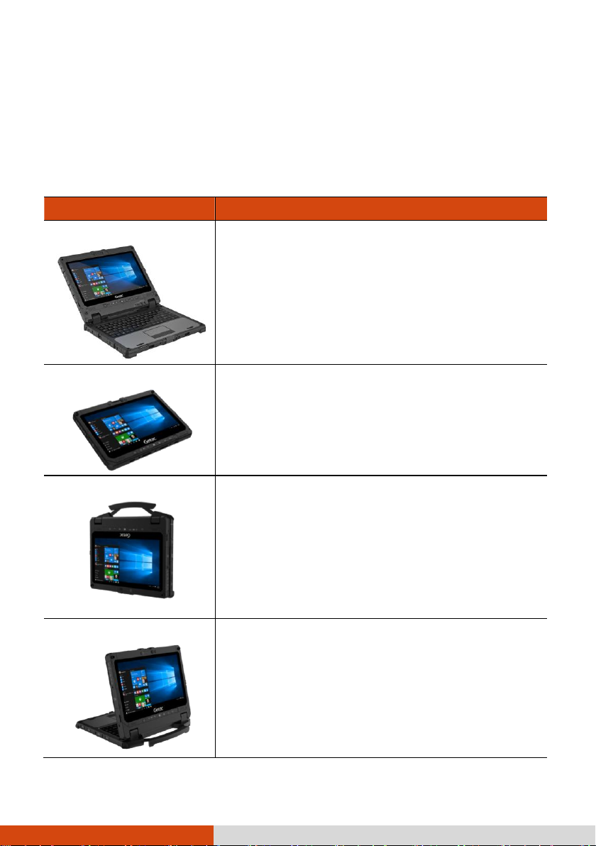
Taking a Look at the Computer ........................................ 6
Tablet Components ...................................................... 6
Keyboard Dock Components ......................................... 13
Multiple Usage Modes .................................................... 17
Attaching and Detaching the Keyboard Dock .................... 18
Chapter 2 Operating Your Computer ...................................................... 19
Navigating on the Screen ............................................... 20
Using the Touchscreen ............................................... 20
Using the Dual Mode Display (Optional) ...................... 23
Using the Keyboard Dock .............................................. 24
Using the Keyboard ................................................... 24
Using the Touchpad .................................................. 28
Using Network and Wireless Connections ........................... 30
Using the LAN ......................................................... 30
Using the WLAN ...................................................... 30
Using the Bluetooth Feature ......................................... 31
Using the WWAN Feature (Optional) ........................... 32
Chapter 3 Managing Power ...................................................................... 34
AC Adapter ................................................................. 35
i
Page 5

Battery Pack ............................................................... 36
Charging the Battery Pack .......................................... 36
Initializing the Battery Pack ......................................... 37
Checking the Battery Level ......................................... 37
Battery Low Signals and Actions .................................. 38
Replacing the Battery Pack ......................................... 38
Power-Saving Tips ........................................................ 41
Chapter 4 Care and Maintenance ............................................................ 42
Protecting the Computer ................................................. 43
Using an Anti-Virus Strategy ....................................... 43
Using the Cable Lock ................................................ 43
Taking Care of the Computer ......................................... 44
Location Guidelines .................................................... 44
General Guidelines .................................................... 44
Cleaning Guidelines ................................................... 45
Battery Pack Guidelines .............................................. 45
Touchscreen Guidelines .............................................. 47
When Traveling ............................................................ 48
Chapter 5 Troubleshooting ...................................................................... 49
Preliminary Checklist ...................................................... 50
Solving Common Problems .............................................. 51
Battery Problems ....................................................... 51
Bluetooth Problems ..................................................... 51
Display Problems ...................................................... 52
Hardware Device Problems .......................................... 52
Keyboard and Touchpad Problems ................................ 53
LAN Problems .......................................................... 53
Power Management Problems ...................................... 54
Software Problems .................................................... 54
Sound Problems ....................................................... 54
Startup Problems ...................................................... 55
WLAN Problems ....................................................... 55
Other Problems ........................................................ 57
System Recovery .......................................................... 58
Using Windows RE ................................................... 58
ii
Page 6

Using Recovery Partition ............................................. 59
Using the Driver Disc (Optional) ..................................... 61
Appendix A Specifications .......................................................................... 62
Tablet Specifications ...................................................... 63
Keyboard Dock Specifications .......................................... 65
Appendix B Regulatory Information ........................................................... 66
On the Use of the System ............................................ 67
Class B Regulations .................................................. 67
ANSI Warning .......................................................... 68
Safety Notices .......................................................... 69
On the Use of the RF Device ....................................... 73
USA and Canada Safety Requirements and Notices ......... 73
European Union CE Marking and Compliance Notices ....... 75
User Notification of Take-back Service ............................. 78
ENERGY STAR 6.1 ...................................................... 79
Battery Recycling ........................................................... 81
iii
Page 7

Chapter 1
This chapter first tells you step by step how to get the computer up and running.
Then, you will find a section briefly introducing the external components of the
computer.
1
Page 8
Getting the Computer Running
Installing the Micro-SIM Card (Optional) and
Battery Packs
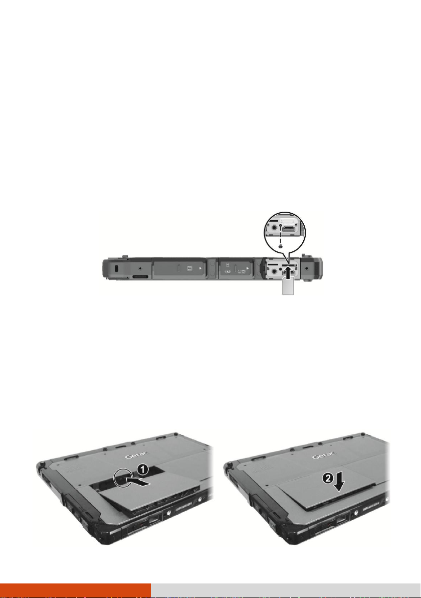
1. Select models only:
The micro-SIM card slot is covered by a metal plate. Remove one screw to
detach the plate.
Noting the orientation, insert the micro-SIM card all the way into the slot.
NOTE: To remove the micro-SIM card, just push in the card to
release it and then pull it out.
2. The Tablet has two battery compartments for two battery packs; each is installed
in the same way.
With the battery pack correctly oriented, attach its connector side to the battery
compartment at an angle () and then press down the other side ().
The battery latch should automatically engage.
2
Page 9

Lock
3. Slide the lock of the battery latch downward to the locked position.
CAUTION: Make sure the battery latch is correctly locked, not
revealing the underneath red part.
Locked: Unlocked (revealing red part):
Connecting to AC Power
CAUTION: Use only the AC adapter included with your computer.
Using other AC adapters may damage the computer.
NOTE:
The battery pack is shipped to you in power saving mode that
protects it from charging/discharging. It will get out of
the mode to be ready for use when you install the battery
pack and connect AC power to the computer for the very first
time.
When the AC adapter is connected, it also charges the battery
pack. For information on using battery power, see Chapter
3.
You must use AC power when starting up the computer for the very first time.
1. K120 Tablet:
Open the cover of the power connector. The cover is protected by a security
lock. Slide the lock outward () to unlock the cover.
Plug the DC cord of the AC adapter to the power connector (). Plug the
female end of the AC power cord to the AC adapter and the male end to an
electrical outlet ().
3
Page 10

K120 Tablet with the Keyboard Dock:
Open the cover of the power connector.
Plug the DC cord of the AC adapter to the power connector (). Plug the
female end of the AC power cord to the AC adapter and the male end to an
electrical outlet ().
2. Power is being supplied from the electrical outlet to the AC adapter and onto
your computer. Now, you are ready to turn on the computer.
4
Page 11
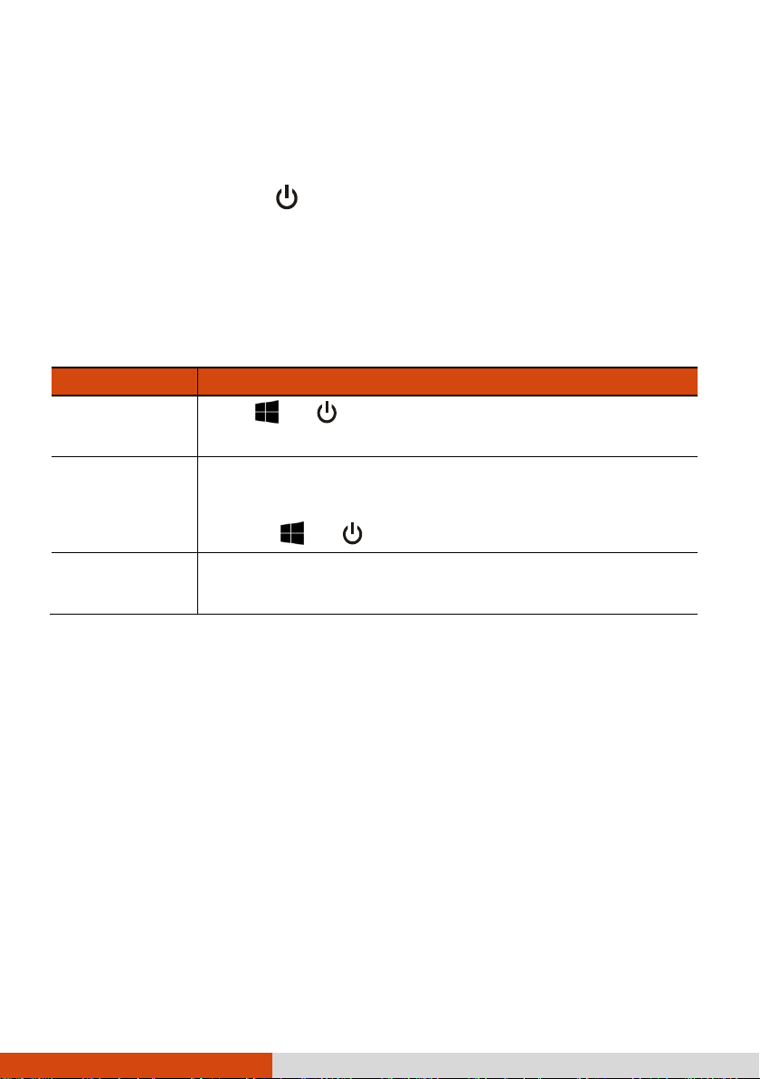
To...
Do this...
Power off
(Shutdown)
Click Power Shut down.
Sleep
Use one of these methods:
Press the power button.*
Click Power Sleep.
Hibernate
By default, this option is not shown in the Start menu. If you
want to use the feature, set up accordingly in Windows settings.
Turning On and Off the Computer
Turning On
Press the power button ( ) for at least 2 seconds until the Power Indicator
lights up. The Windows operating system should start.
Turning Off
When you finish a working session, you can stop the system by turning off the
power or leaving it in Sleep or Hibernation mode:
* “Sleep” is the default result of the action. You can change what the action
does through Windows settings.
5
Page 12
Taking a Look at the Computer
NOTE: Depending on the model you purchased, the appearance of
your computer may not be exactly the same as those shown in this
manual.
CAUTION: You need to open the protective covers to access the
connectors. When not using a connector, make sure to close the
cover completely for water- , dust-, and fire-proof integrity.
(Engage the locking mechanism if existing.)
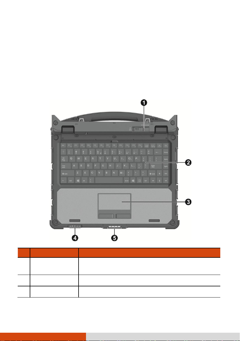
Tablet Components
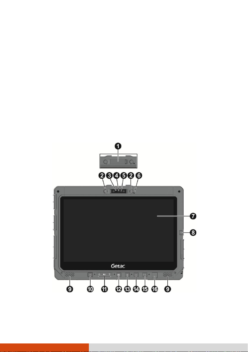
Front Components
6
Page 13

Ref
Component
Description
Camera cover
(optional)
Covers the camera lens.
Slide the camera cover toward the right to use the camera;
slide it toward the left for privacy protection.
Microphone
Receives sound and voice to record voice.
Camera indicator
(optional)
Lights up when the camera is in use.
IR sensor
(optional)
Detects the infrared energy of objects to form an image.
The sensor flashes red light when in use.
The near infrared (IR) imaging capability allows you to
use Windows Hello face authentication.
Camera lens
(optional)
Allows you to use the camera function.
Light sensor
Detects the surrounding lighting condition for automatic
adjustment of the LCD brightness.
Touchscreen
Displays and receives information for the computer.
P2 button
The default function is Camera or Trigger depending on your
model.
Camera
Starts the G-Camera application.
Trigger
Serves as the trigger button for the barcode
reader if your model has the module.
Stereo speaker
Sends out sound and voice from your computer.
Power button
Turns the power on or off. (The default “off” state is
“Sleep mode.”)
With a default setting of 2-second delay, you have to
press the button for at least 2 seconds for it to function.
Indicators
Power
Lights blue when the power is on.
7
Page 14
Blinks blue when the system is in Sleep mode.
Battery
Lights amber when the battery is being charged.
Lights green when battery charging is completed.
Ref
Component
Description
Blinks green to indicate the battery’s built-in high
temperature protection mechanism is activated.
CAUTION: Do not remove the battery during
this period.
Blinks red (once per second) when the battery’s capacity
is below 10%.
Blinks red rapidly (once per 0.5 second) when there
is a thermal protection problem. Ask for repair service
in case this happens.
Blinks amber when the battery charging is in an abnormal
state. Replace the battery in case this happens.
RF (Radio
Frequency)
Lights blue when the RF radio of any RF feature
(WLAN/Bluetooth/WWAN) is on.
Windows logo
button
Opens or closes the Start menu.
Plus button
Increases the sound volume.
Minus button
Decreases the sound volume.
P1 button
Opens or closes the OSD Control Panel.
When pressed longer:
Serves as the Ctrl+Alt+Del keyboard keys.
Fingerprint
scanner
Serves as the fingerprint verification, preventing
unauthorized access to your computer.
NOTE: The hardware buttons (except the power button) can be
re-defined using G-Manager.
8
Page 15
Ref
Component
Description
Flash (optional)
Provides extra light when taking pictures.
Camera lens
(optional)
Allows you to use the camera function. When the camera
lens is in use, the indicator beside it lights up.
NFC/RFID reader
(optional)
Reads data from NFC/RFID tags.
Battery pack
Supplies power to your computer when external power
is not connected.
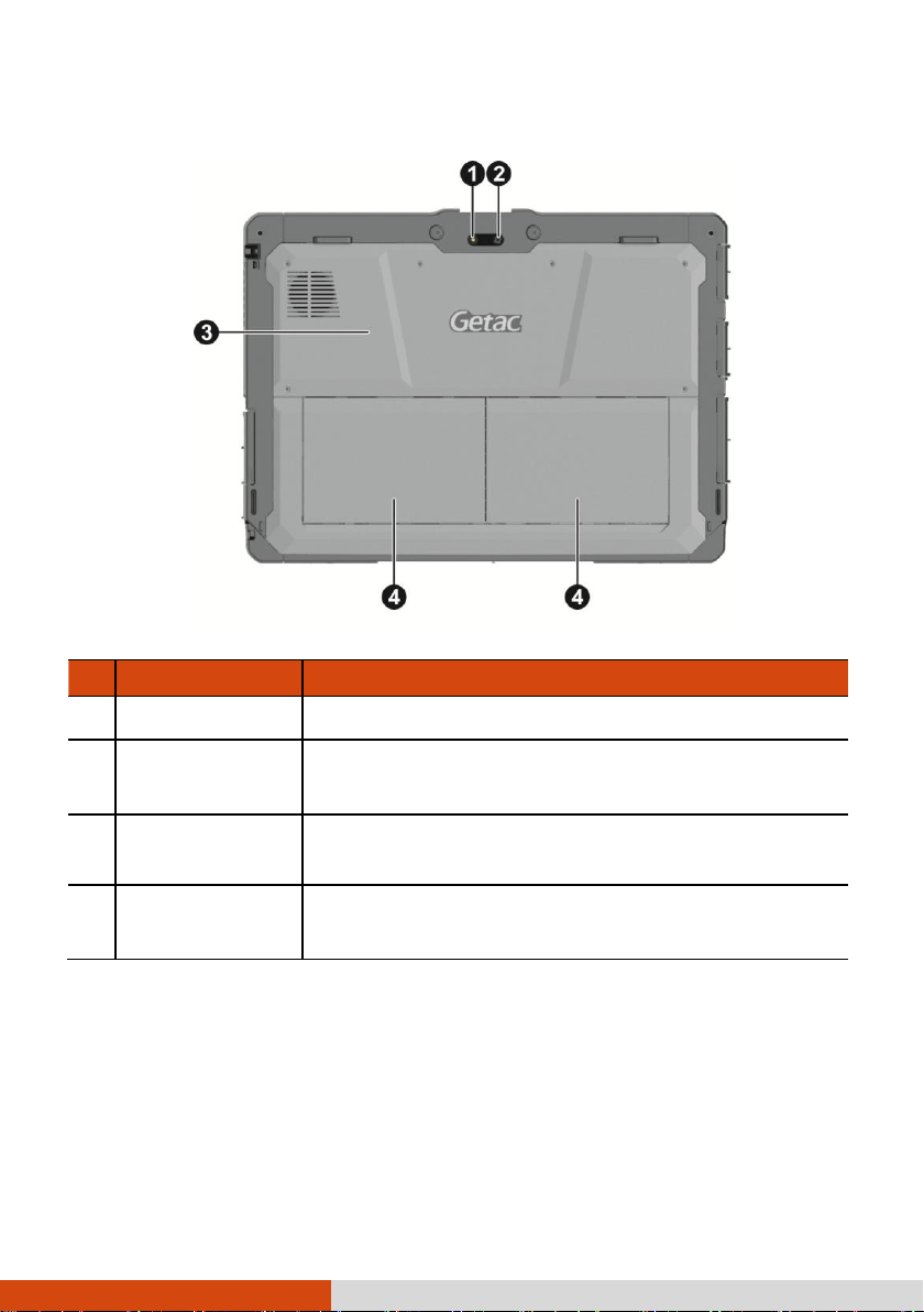
Rear Components
9
Page 16
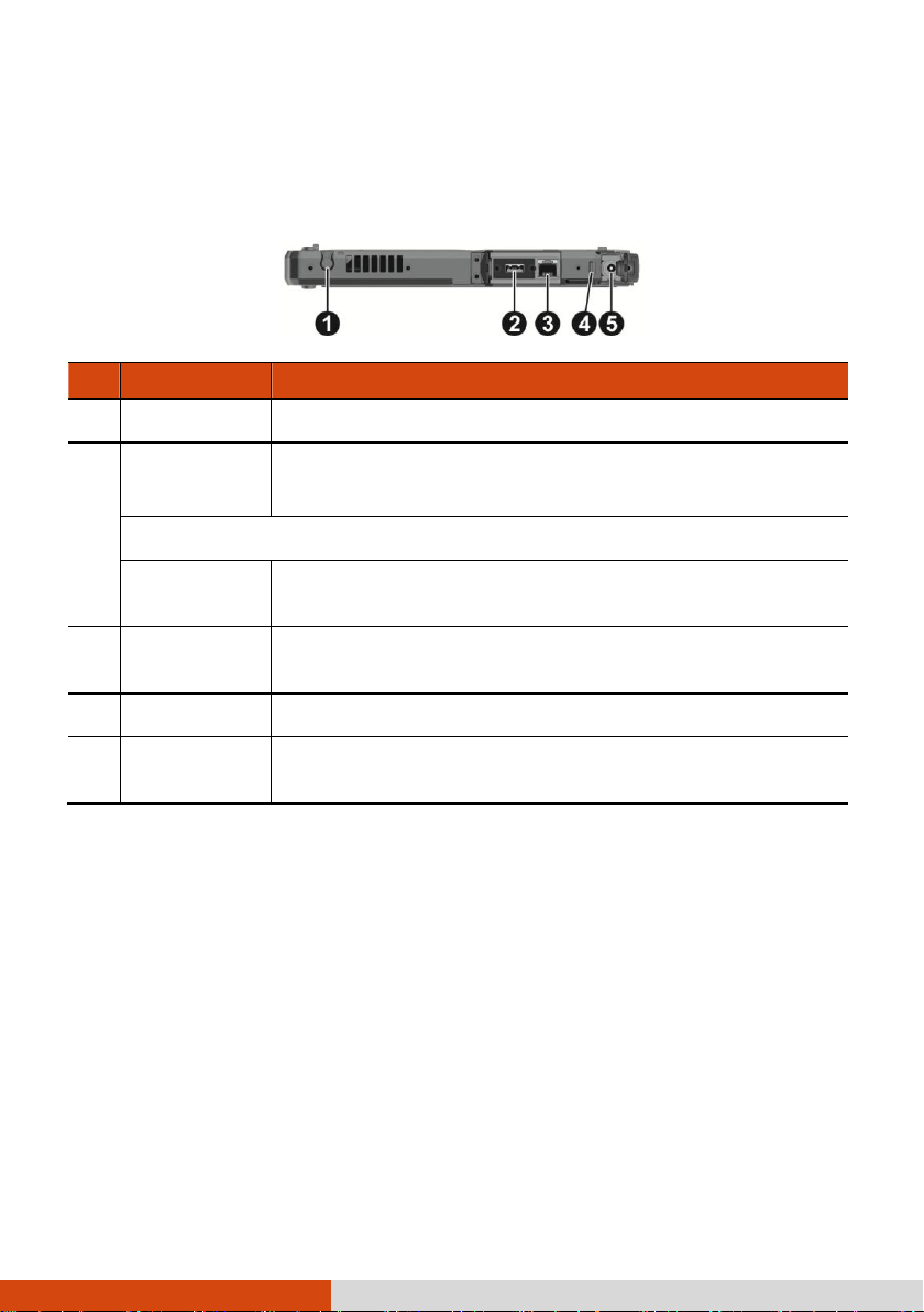
Ref
Component
Description
Stylus holder
Holds the stylus.
USB 2.0 port
Connects a USB device, such as a USB flash disk, printer,
digital camera, joystick, and more.
- or -
RS232 serial
connector
Connects a serial mouse or serial communication device.
RJ-45
connector
Connects the LAN cable.
Security lock
Locks the cover of the power connector.
Power
connector
Connects the AC adapter.
Right-Side Components
For covers with an arrowhead icon, push the cover toward one side to unlock and
the other side to lock. The arrowhead points to the side for unlocking.
10
Page 17
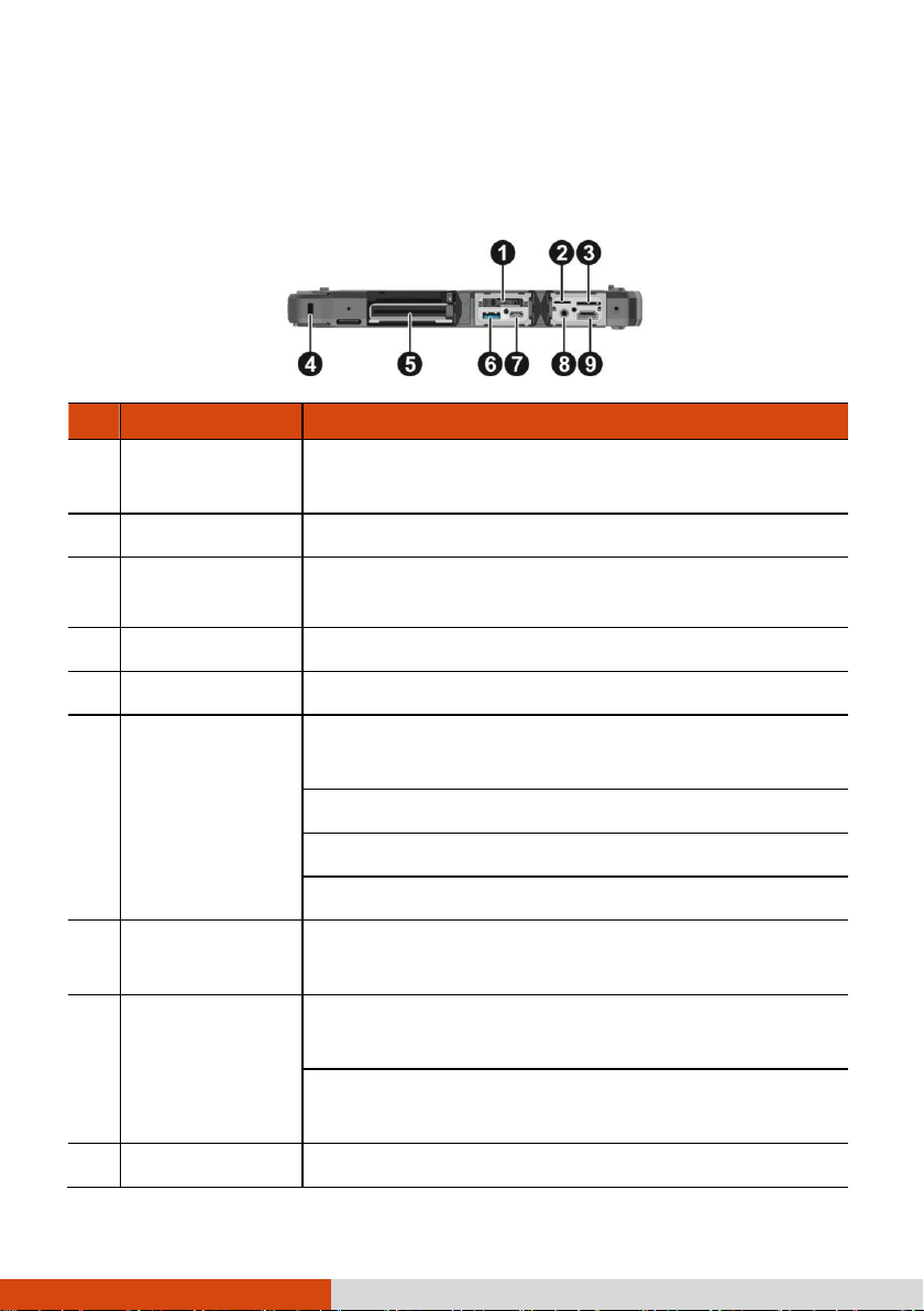
Ref
Component
Description
SSD canister
Contains the solid-state drive, which is the mass storage
device of your computer.
MicroSD card slot
Accepts a microSD card for removable storage media.
Micro-SIM card
slot (optional)
Accepts a micro-SIM card for models having the WWAN
module.
Kensington lock
Locks the computer to a stationary object for security.
Smart card reader
Accepts a smart card for additional security feature.
PowerShare USB
port
Provides either of the below two functions depending on
your setting.
Charges a connected mobile device.
- or -
Functions as a standard USB 3.0 port (default setting).
USB 3.1 Gen 1
Type-C port
Connects a USB device that supports USB Type-C
connection.
Combo audio
connector
Connects a set of headphones or external speakers with
amplifier.
Supports a headset microphone with 4-pole TRRS 3.5mm
jack.
HDMI connector
Connects a HDMI monitor or TV set.
Left-Side Components
For covers with an arrowhead icon, push the cover toward one side to unlock and
the other side to lock. The arrowhead points to the side for unlocking.
11
Page 18
Ref
Component
Description
Barcode reader
lens (optional)
Scans and reads barcodes.
Ref
Component
Description
Battery release
latch
Releases the battery pack. The latch has a locking
mechanism.
Docking
connectors
Connects a proprietary dock such as the keyboard dock,
office dock, and vehicle dock.
Top Components
Bottom Components
12
Page 19
Ref
Component
Description
Tablet release
latch
Releases the Tablet. The latch has a locking mechanism.
Keyboard
Serves as the data input device of the computer.
Touchpad
Serves as the pointing device of the computer.
Keyboard Dock Components
NOTE:
The Keyboard Dock can be purchased separately. Specific
models come with the Keyboard Dock.
See “Attaching and Detaching the Keyboard Dock” later in this
chapter for more information.
Top Components
13
Page 20
Ref
Component
Description
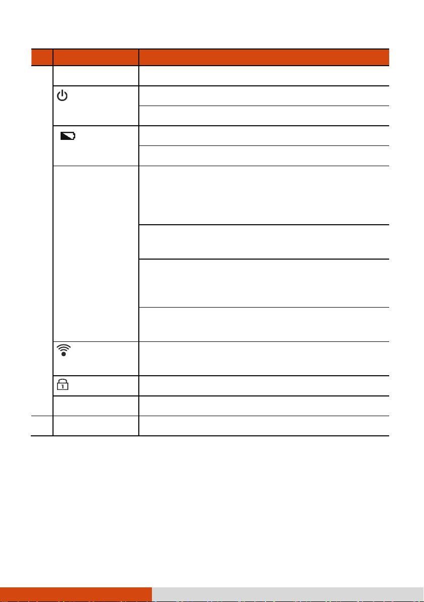
Indicators
Power
Lights green when computer is on.
Blinks green when computer is in Sleep mode.
Battery
Lights amber when the battery is being charged.
Lights green when battery charging is completed.
Blinks green to indicate the battery’s built-in high
temperature protection mechanism is activated.
CAUTION: Do not remove the battery during
this period.
Blinks red (once per second) when the battery’s capacity
is below 10%.
Blinks red rapidly (once per 0.5 second) when there
is a thermal protection problem. Ask for repair service
in case this happens.
Blinks amber when the battery charging is in an abnormal
state. Replace the battery in case this happens.
RF (Radio
Frequency)
Lights green when the RF radio of any RF feature
(WLAN/Bluetooth/WWAN) is on.
Num Lock
Lights green when Num Lock is on.
Caps Lock
Lights green when Caps Lock is on.
Top cover latch
Locks the top cover.
14
Page 21
Ref
Component
Description
USB 3.0 port
Connects a USB device, such as a USB flash disk,
printer, digital camera, joystick, and more.
SD card slot
Accepts a SD card for removable storage media.
RS232 serial
connector
Connects a serial mouse or serial communication device.
Power connector
Connects the AC adapter.
Ref
Component
Description
Kensington lock
Locks the computer to a stationary object for security.
VGA connector
Connects an external display monitor.
HDMI connector
Connects a HDMI monitor or TV set.
RJ-45 connector
Connects the LAN cable.
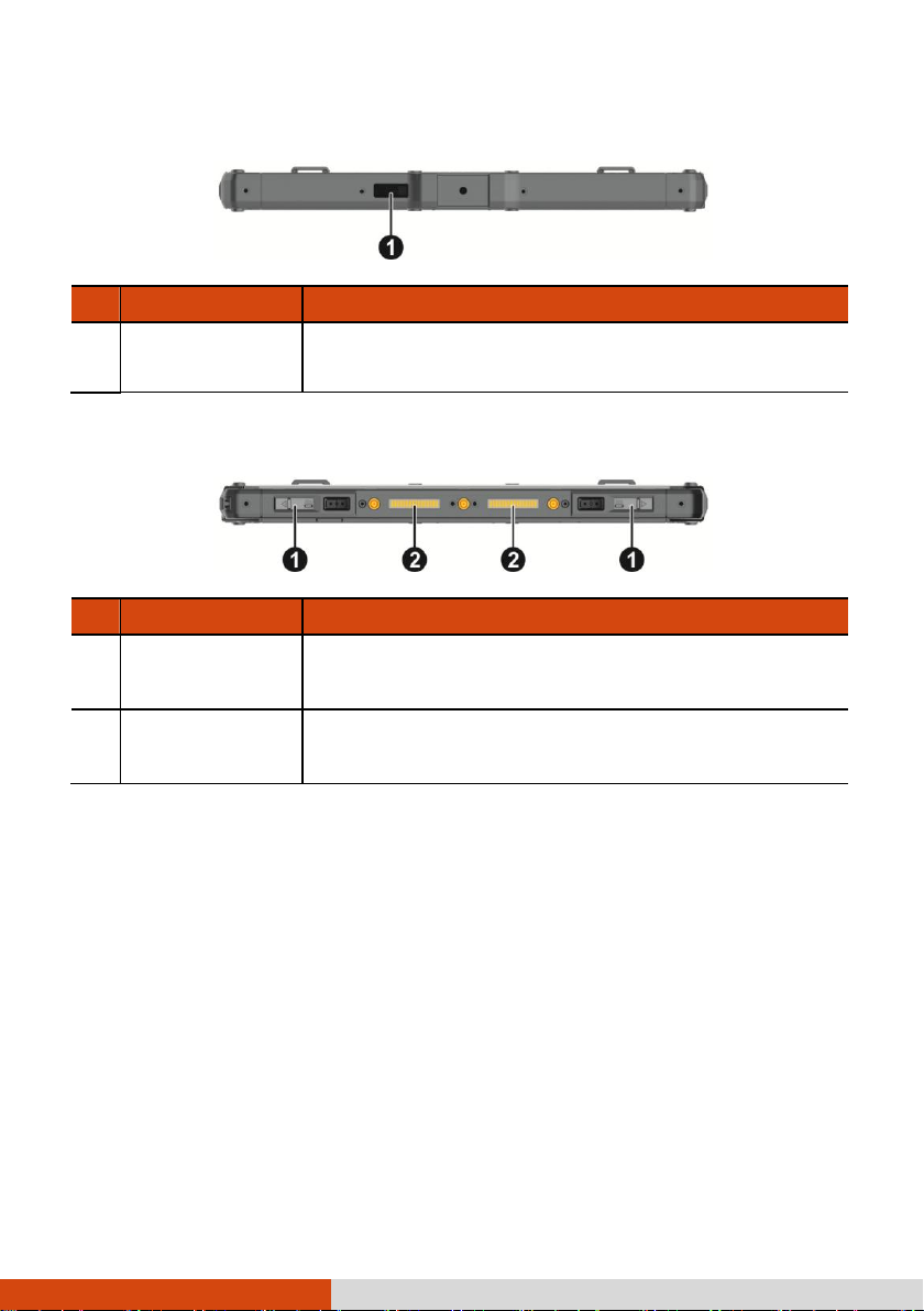
Right-Side Components
For covers with an arrowhead icon, push the cover toward one side to unlock and
the other side to lock. The arrowhead points to the side for unlocking.
Left-Side Components
For covers with an arrowhead icon, push the cover toward one side to unlock and
the other side to lock. The arrowhead points to the side for unlocking.
15
Page 22
Ref
Component
Description
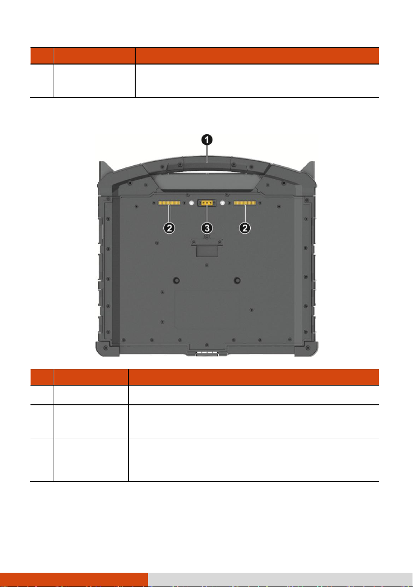
USB 3.0 port
Connects a USB device, such as a USB flash disk,
printer, digital camera, joystick, and more.
Ref
Component
Description
Handle
Provides a convenient way to carry the computer.
Docking
connectors
Connects a proprietary dock such as the office dock and
vehicle dock.
Antenna passthrough
(optional)
Connects to the docking station for using external
WWAN/WLAN/GPS antenna.
Bottom Components
16
Page 23
Usage Mode
Description
Notebook Mode
When the Tablet and Keyboard Dock are assembled,
the system works as a regular notebook computer.
NOTE: See “Attaching and Detaching the
Keyboard Dock” later for more
information.
Tablet Mode
You can easily detach the Keyboard Dock and leave
it behind when you desire the portability of the Tablet.
Convertible Mode
You can transform the system from notebook to tablet
and back again.
For the transformation, the Tablet has to be detached,
flip over, and then reattached.
NOTE: See “Attaching and Detaching the
Keyboard Dock” later for more
information.
Presentation Mode
When the Tablet faces outwards, you can use the
Keyboard Dock as a stand for the Tablet.
Multiple Usage Modes
NOTE: The Keyboard Dock can be purchased separately. Specific
models come with the Keyboard Dock.
With the Keyboard Dock, you can use K120 in different modes.
17
Page 24

Attaching and Detaching the Keyboard Dock
To attach the Keyboard Dock:
1. Depending on the desired usage mode, have the Tablet face either inwards or
outwards.
Align and put the Tablet on the holder. The latches should click into place.
2. Push the lock upward to the locked position.
To detach the Keyboard Dock:
1. Push the lock downward to the unlocked position.
2. Slide the release latch toward the right, and while holding the latch, lift the
Tablet out of the holder.
18
Page 25

Chapter 2
This chapter provides information about the use of the computer.
If you are new to computers, reading this chapter will help you learn the operating
basics. If you are already a computer user, you may choose to read only the parts
containing information unique to your computer.
CAUTION:
Do not expose your skin to the computer when operating it
in a very hot or cold environment.
The computer can get uncomfortably warm when you use it in
high temperatures. As a safety precaution in such a
circumstance, do not place the computer on your lap or touch
it with your bare hands for extended periods of time.
Prolonged body contact can cause discomfort and potentially
a burn.
19
Page 26
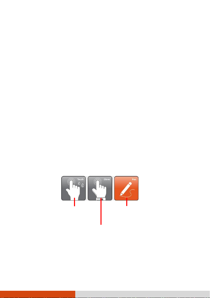
Select this if you are using the
stylus. (You must use the one
Select this if you are wearing gloves (referring
to warm gloves or work gloves, not referring to
Select this if you prefer using
fingertips. Also, select this when
raindrops are falling
on the screen and should be
Navigating on the Screen
The screen of your computer is touch-sensitive. You can operate the computer by
touching the screen with your finger or the stylus.
CAUTION: Do not use a sharp object such as a ballpoint pen or
pencil on the touchscreen. Doing so may damage the touchscreen
surface.
NOTE: An optical film has been attached to the screen before
shipment. The film is a consumable, which will be worn out by
possible scratches. You can purchase a new one when replacement
is required.
Using the Touchscreen
Your computer has a capacitive touchscreen. This type of touchscreen responds to
objects that have conductive properties, such as fingertips and a capacitive-tipped
stylus.
You can change the touchscreen sensitivity settings to suit your scenario. Double-tap
the Touch Screen Mode shortcut on Windows desktop to open the settings menu and
select one of the options (as shown below).
NOTE: If liquid is spilled on the touchscreen causing a wet area,
the area will stop responding to any inputs. For the area to
function again, you must dry it.
20
Page 27
Term/Action
Equivalent Mouse
Function
Tap: Touch the screen once.
Click/Point
Double-tap: Touch the screen twice rapidly.
Double-click
Tap and hold: Tap and hold until a popup menu appears.
Right-click
Drag: Hold the stylus (or finger) on the screen and drag across
the screen until reaching your destination.
Drag
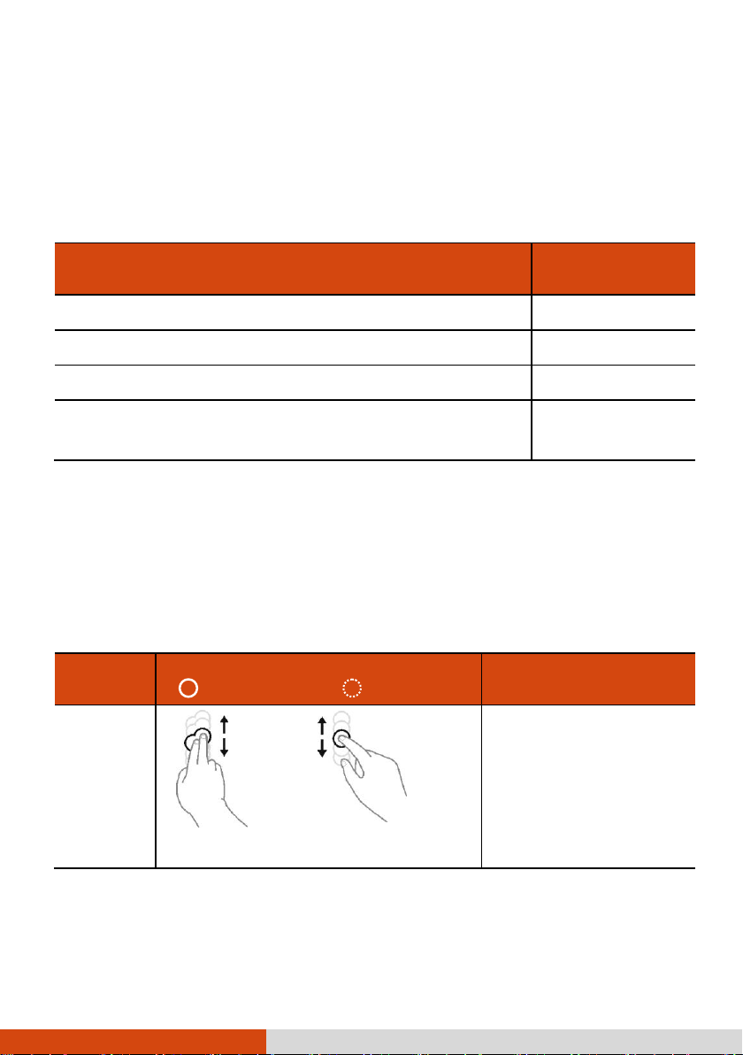
Gestures
Actions
( = finger down; = finger up)
Descriptions
Pan
(Scroll)
or
Drag 1 or 2 fingers up or down.
Use panning to see
another part of a page that
has scroll bars.
The following table shows how you use the touchscreen to obtain equivalent mouse
functions.
Using Multi-touch Gestures
You can interact with your computer by placing two fingers on the screen. The
movement of the fingers across the screen creates “gestures,” which send commands
to the computer.
Here are the multi-touch gestures that you can use:
21
Page 28

Gestures
Actions
( = finger down; = finger up)
Descriptions
Zoom
(Pinch)
Move two fingers apart/toward each
other.
Use zooming to make an
item (a photo for
example) on the screen
larger or smaller. The
gesture works in
applications that support
mouse wheel zooming.
Rotate
or
Move two fingers in opposing directions.
-orUse one finger to pivot around another.
Use rotating to move a
picture or other item on
the screen in a circular
direction (clockwise or
counterclockwise). The gesture
works in applications that
support the specific
gesture.
Press and
Tap
Press on target and tap using a second
finger.
Use press and tap to
access the shortcut
menu.
Twofinger Tap
Tap two fingers at the same time (where
the target is in the midpoint between the
fingers).
The function is defined by
applications that support
the specific gesture.
22
Page 29

Gestures
Actions
( = finger down; = finger up)
Descriptions
Flicks
Make quick drag gestures in the desired
direction.
Flick left or right to
navigate back and forward
in a browser and other
applications. The gesture
works in most applications
that support back and
forward.
Using the Dual Mode Display (Optional)
Dual mode display (if your model has the feature) incorporates both touchscreen
and digitizer functions.
The display is set to Touchscreen mode by default. Touchscreen mode provides
all the functionalities that an ordinary touchscreen has. When the Computer receives
signals from the digitizer pen, the display automatically switches to Digitizer mode.
You can move the cursor by bringing the digitizer pen close to the screen, without
actually touching the screen’s surface.
23
Page 30

Using the Keyboard Dock
NOTE: The Keyboard Dock can be purchased separately. Specific
models come with the Keyboard Dock.
Using the Keyboard
Your keyboard has all the standard functions of a full-sized computer keyboard plus
an Fn key added for specific functions.
The standard functions of the keyboard can be further divided into four major
categories:
Typewriter keys
Cursor-control keys
Numeric keys
Function keys
Typewriter Keys
Typewriter keys are similar to the keys on a typewriter. Several keys are added
such as the Ctrl, Alt, Esc, and lock keys for special purposes.
The Control (Ctrl) / Alternate (Alt) key is normally used in combination with other
keys for program-specific functions. The Escape (Esc) key is usually used for
stopping a process. Examples are exiting a program and canceling a command.
The function depends on the program you are using.
Cursor-Control Keys
Cursor-control keys are generally used for moving and editing purposes.
NOTE: The word “cursor” refers to the indicator on the screen
that lets you know exactly where on your screen anything you
type will appear. It can take the form of a vertical or
horizontal line, a block, or one of many other shapes.
24
Page 31

Numeric Keypad
A 15-key numeric keypad is embedded in the typewriter keys as shown next:
Numeric keys facilitate entering of numbers and calculations. When Num Lock is
on, the numeric keys are activated; meaning you can use these keys to enter
numerals.
NOTE:
When the numeric keypad is activated and you need to type
the English letter in the keypad area, you can turn Num Lock
off or you can press Fn and then the letter without turning
Num Lock off.
Some software may not be able to use the numeric keypad on
the computer. If so, use the numeric keypad on an external
keyboard instead.
The Num Lock key can be disabled.
25
Page 32

Key
Description
Switches the keyboard backlight on and off (option).
Switches the RF (radio frequency) radio on and off.
When off, all wireless modules (such as WLAN, Bluetooth, and
WWAN) cannot be used. When on, individual settings of the
module work.
Decreases the sound volume.
Increases the sound volume.
Function Keys
On the top row of the keys are the function keys: F1 to F12. Function keys are
multi-purpose keys that perform functions defined by individual programs.
Fn Key
The Fn key, at the lower left corner of the keyboard, is used with another key
to perform the alternative function of a key. To perform a desired function, first press
and hold Fn, then press the other key.
Hot Keys
Hot keys refer to a combination of keys that can be pressed any time to activate
special functions of the computer. Most hot keys operate in a cyclic way. Each
time a hot key combination is pressed, it shifts the corresponding function to the
other or next choice.
You can easily identify the hot keys with the icons imprinted on the keytop. The
hot keys are described next.
26
Page 33

Key
Description
Switches the display output to the next choice if an external display
is connected. Choices are:
LCD only
LCD + External display (Duplicate)
LCD + External display (Extend)
External display only
The hot keys are equivalent to Windows logo key + P.
Decreases the LCD brightness.
Increases the LCD brightness.
Switches the touchscreen on or off.
Switches the touchpad off or on.
Switches the system sound output off (mute) or on.
Switches the display on or off.
Serves as the sleep button that you can define with Windows’
Power Options.
Windows Keys
The keyboard has two keys that perform Windows-specific functions: Windows
Logo key and Application key.
27
Page 34

Term
Action
Point
Move your finger on the pad until the cursor points to the
selection on the screen.
Click
Press and release the left button.
–or–
Tap gently anywhere on the pad.
The Windows Logo key opens the Start menu and performs softwarespecific functions when used in combination with other keys. The Application
key usually has the same effect as a right mouse click.
Using the Touchpad
CAUTION: Do not use a sharp object such as a pen on the touchpad.
Doing so may damage the touchpad surface.
NOTE:
Press Fn+F9 to toggle the touchpad on or off.
For optimal performance of the touchpad, keep your fingers
and the pads clean and dry. When tapping on the pad, tap
lightly. Do not use excessive force.
The touchpad is a pointing device that allows you to communicate with the computer
by controlling the location of the pointer on the screen and making selection with
the buttons.
The touchpad consists of a rectangular pad (work surface) and a left and right
buttons. To use the touchpad, place your forefinger or thumb on the pad. The
rectangular pad acts like a miniature duplicate of your display. As you slide your
fingertip across the pad, the pointer (also called cursor) on the screen moves
accordingly. When your finger reaches the edge of the pad, simply relocate yourself
by lifting the finger and placing it on the other side of the pad.
Here are some common terms that you should know when using the touchpad:
28
Page 35

Term
Action
Double-click
Press and release the left button twice in quick succession.
–or–
Tap twice on the pad rapidly.
Drag and drop
Press and hold the left button, then move your finger until
you reach your destination (drag). Finally, release the button
(drop) when you finish dragging your selection to the
destination. The object will drop into the new location.
–or–
Gently tap twice on the pad and on the second tap, keep
your finger in contact with the pad. Then, move your finger
across the pad to drag the selected object to your destination.
When you lift your finger from the pad, the selected object
will drop into place.
Touch Gestures for Windows 10
The touchpad supports touch gestures for Windows 10 such as one-finger scrolling,
two-finger scrolling, pinch zoom, rotating, and others. For detailed information, go
to Settings Devices Mouse & touchpad Additional mouse options Device
Settings Settings.
Configuring the Touchpad
You may want to configure the touchpad to suit your needs. For example, if you
are a left-handed user, you can swap the two buttons so that you can use the
right button as the left button and vice versa. You can also change the size of
the on-screen pointer, the speed of the pointer, and so on.
To configure the touchpad, go to Settings Devices Mouse & touchpad.
29
Page 36

Using Network and Wireless
Connections
Using the LAN
To connect the network cable to the LAN module, connect one end of the LAN
cable to the RJ-45 connector on the computer and the other end to the network
hub.
Using the WLAN
The WLAN (Wireless Local Area Network) module of your computer supports IEEE
802.11a/b/g/n/ac.
Turning On/Off the WLAN Radio
To turn on the WLAN radio:
Click Settings Network & Internet Wi-Fi. Slide the Wi-Fi switch to the
On position.
To turn off the WLAN radio:
You can turn off the WLAN radio the same way you turn it on.
If you want to quickly turn off all wireless radio, simply switch on Airplane mode.
You can control the Airplane mode using one of the below methods.
Press Fn+F1.
Use the Airplane Mode button in the OSD Control Panel.
Click Settings Network & Internet Airplane mode.
Connecting to a WLAN Network
1. Make sure that the WLAN function is enabled (as described above).
2. Click the network icon in the lower right of the task bar.
30
Page 37

3. Select the device you want to connect from the search results.
4. Some networks require a network security key or passphrase. To connect to
one of those networks, ask your network administrator or Internet service provider
(ISP) for the security key or passphrase.
For more information on setting a wireless network connection, refer to Windows
online help.
Using the Bluetooth Feature
The Bluetooth technology allows short-range wireless communications between devices
without requiring a cable connection. Data can be transmitted through walls, pockets
and briefcases as long as two devices are within range.
Turning On/Off the Bluetooth Radio
To turn on the Bluetooth radio:
Click Settings Devices Bluetooth. Slide the Bluetooth switch to the
On position.
To turn off the Bluetooth radio:
You can turn off the Bluetooth radio the same way you turn it on.
If you want to quickly turn off all wireless radio, simply switch on Airplane mode.
You can control the Airplane mode using one of the below methods.
Press Fn+F1.
Use the Airplane Mode button in the OSD Control Panel.
Click Settings Network & Internet Airplane mode.
Connecting to another Bluetooth Device
1. Make sure that the Bluetooth function is enabled (as described above).
2. Make sure that the target Bluetooth device is turned on, discoverable and within
close range. (See the documentation that came with the Bluetooth device.)
31
Page 38

3. Click Settings Devices Bluetooth.
4. Select the device you want to connect from the search results.
5. Depending on the type of Bluetooth device that you want to connect to, you
will need to enter the pertinent information.
For detailed information on using the Bluetooth feature, see Windows’ online Help.
Using the WWAN Feature (Optional)
A WWAN (Wireless Wide Area Network) uses mobile telecommunication cellular
network technologies to transfer data. The WWAN module of your computer supports
3G and 4G LTE.
NOTE: Your model only supports data transmission. Voice
transmission is not supported.
Turning On/Off the WWAN Radio
To turn on the WWAN radio:
Click Settings Network & Internet Airplane mode. Slide the Cellular
switch to the On position.
To turn off the WWAN radio:
You can turn off the WWAN radio the same way you turn it on.
If you want to quickly turn off all wireless radio, simply switch on Airplane mode.
You can control the Airplane mode using one of the below methods.
Press Fn+F1.
Use the Airplane Mode button in the OSD Control Panel.
Click Settings Network & Internet Airplane mode.
32
Page 39

Setting up a WWAN Connection
Tap Settings Network & Internet Cellular. (For detailed information on
cellular settings in Windows 10, see Microsoft Support website.)
33
Page 40

Chapter 3
Your computer operates either on external AC power or on internal battery power.
This chapter tells you how you can effectively manage power. To maintain optimal
battery performance, it is important that you use the battery in the proper way.
34
Page 41

AC Adapter
CAUTION:
The AC adapter is designed for use with your Computer only.
Connecting the AC adapter to another device can damage the
adapter.
The AC power cord supplied with your Computer is for use in
the country where you purchased your Computer. If you plan
to go overseas with the Computer, consult your dealer for
the appropriate power cord.
When you disconnect the AC adapter, disconnect from the
electrical outlet first and then from the Computer. A reverse
procedure may damage the AC adapter or Computer.
When unplugging the connector, always hold the plug head.
Never pull on the cord.
The AC adapter serves as a converter from AC (Alternating Current) to DC (Direct
Current) power because your Computer runs on DC power, but an electrical outlet
usually provides AC power. It also charges the battery pack when connected to AC
power.
The adapter operates on any voltage in the range of 100~240 V AC.
35
Page 42

Battery Pack
Your computer has two battery packs. The battery pack is the internal power source
for the computer. It is rechargeable using the AC adapter.
NOTE: Care and maintenance information for the battery is
provided in the “Battery Pack Guidelines” section in Chapter
7.
Charging the Battery Pack
NOTE:
Charging will not start if the battery’s temperature is
outside the allowed range, which is between 0 C (32 F) and
50 C (122 F). Once the temperature meets the requirements,
charging automatically resumes.
During charging, do not disconnect the AC adapter before the
battery has been fully charged; otherwise you will get a
prematurely charged battery.
The battery has a high temperature protection mechanism
which limits the maximum charge of the battery to 80% of its
total capacity in the event of high temperature conditions.
In such conditions, the battery will be regarded as fully
charged at 80% capacity.
The battery level may automatically lessen due to the
self-discharge process (0.21% per day), even when the
battery pack is fully charged (100%). This happens no matter
if the battery pack is installed in the computer.
To charge the battery pack, connect the AC adapter to the computer and an electrical
outlet. The Battery Indicator ( ) on the computer glows amber to indicate that
charging is in progress. You are advised to keep the computer power off while the
battery is being charged. When the battery is fully charged, the Battery Charge
Indicator glows green.
The two battery packs are charged in parallel. It takes approximately 5 hours to
fully charge the two battery packs when the power is off and approximately 6 hours
when the power is on (may need a longer charging time at lower temperatures).
36
Page 43

CAUTION: After the computer has been fully recharged, do not
immediately disconnect and reconnect the AC adapter to charge
it again. Doing so may damage the battery.
Initializing the Battery Pack
You need to initialize a new battery pack before using it for the first time or when
the actual operating time of a battery pack is much less than expected. Initializing
is the process of fully charging, discharging, and then charging. It can take several
hours.
A software tool called “Gauge Reset” is provided for the purpose. Use the G-Manager
program and select the Battery tab to find the tool.
Checking the Battery Level
NOTE: Any battery level indication is an estimated result. The
actual operating time can be different from the estimated time,
depending on how you are using the computer.
The operating time of a fully charged battery pack depends on how you are using
the computer. When your applications often access peripherals, you will experience
a shorter operating time.
The two battery packs are discharged in parallel.
By Operating System
You can check the approximate battery level using the battery meter function of the
operating system. To read the battery level in Windows, click the battery icon on the
taskbar.
By Gas Gauge
On the exterior side of the battery pack is a gas gauge for displaying the estimated
battery charge. When the battery pack is not installed in the computer and you want
to know the battery charge, you can press the push-button to see the number of
LEDs that light up. Each LED represents 20% charge.
37
Page 44

Battery
Icon
Battery Level
Description
Discharging
The icon shows the charge remaining in 10-percent
increments until the charge reaches the low-battery level.
Low
The battery charge has reached the low-battery level.
Critically
low
The battery charge has reached the critical battery level.
By default, Windows will display a notification and put your
computer into Hibernation.
Battery Low Signals and Actions
The battery icon changes appearance to display the current state of the battery.
When the battery is low, the computer’s Batter Indicator ( ) also blinks red
to alert you to take actions.
Always respond to low-battery by connecting the AC adapter, placing your computer
in Hibernation mode, or turning off the computer.
Replacing the Battery Pack
CAUTION:
There is danger of explosion if the battery is incorrectly
replaced. Replace the battery only with the computer
manufacturer’s battery packs. Discard used batteries
according to the dealer’s instructions.
Do not attempt to disassemble the battery pack.
NOTE: You can hot swap one battery pack while the other one is
supplying the power.
To replace the battery pack, follow these steps:
1. If the Keyboard Dock is connected, detach it.
38
Page 45

2. Slide the lock of the battery latch upwards to the unlocked position.
3. Slide the battery latch toward the left (). The battery pack will slightly pop
up. Remove the battery pack from its compartment ().
4. Fit another battery pack into place. With the battery pack correctly oriented, attach
its connector side to the battery compartment at an angle () and then press
down the other side (). The battery latch should automatically engage.
5. Slide the lock of the battery latch downward to the locked position.
CAUTION: Make sure the battery latch is correctly locked, not
revealing the underneath red part.
Locked: Unlocked (revealing red part):
39
Page 46

40
Page 47

Power-Saving Tips
Aside from enabling your computer’s power saving mode, you can do your part to
maximize the battery’s operating time by following these suggestions.
Do not disable Power Management.
Decrease the LCD brightness to the lowest comfortable level.
Shorten the length of time before Windows turn off the display.
When not using a connected device, disconnect it.
Turn off the wireless radio if you are not using the wireless module (such as
WLAN, Bluetooth, or WWAN).
Turn off the computer when you are not using it.
41
Page 48

Chapter 4
Taking good care of your computer will ensure a trouble-free operation and reduce
the risk of damage to your computer.
This chapter gives you guidelines covering areas such as protecting, storing, cleaning,
and traveling.
42
Page 49

Protecting the Computer
To safeguard the integrity of your computer data as well as the computer itself,
you can protect the computer in several ways as described in this section.
Using an Anti-Virus Strategy
You can install a virus-detecting program to monitor potential viruses that could
damage your files.
Using the Cable Lock
You can use a Kensington-type cable lock to protect your computer against theft.
The cable lock is available in computer stores.
To use the lock, loop the lock cable around a stationary object such as a table.
Insert the lock to the Kensington lock hole and turn the key to secure the lock.
Store the key in a safe place.
43
Page 50

Taking Care of the Computer
Location Guidelines
For optimal performance, use the computer where the recommended temperature
is between 0 C (32 F) and 55 C (131 F). (Actual operating temperature
depends on product specifications.)
Avoid placing the computer in a location subject to high humidity, extreme
temperatures, mechanical vibration, direct sunlight, or heavy dust. Using in
extreme environments for long periods can result in product deterioration and
a shortened product life.
Operating in an environment with metallic dust is not allowed.
Place the computer on a flat and steady surface. Do not stand the computer
on its side or store it in an upside-down position. A strong impact by dropping
or hitting may damage the computer.
Do not cover or block any ventilation openings on the computer. For example,
do not place the computer on a bed, sofa, rug, or other similar surface.
Otherwise, overheating may occur that results in damage to the computer.
As the computer can become very hot during operation, keep it away from objects
that are vulnerable to heat.
Keep the computer at least 13 cm (5 inches) away from electrical appliances
that can generate a strong magnetic field such as a TV, refrigerator, motor,
or a large audio speaker.
Avoid moving the computer abruptly from a cold to a warm place. A temperature
difference of more than 10 C (18 F) may cause condensation inside the unit,
which may damage the storage media.
General Guidelines
Do not place heavy objects on top of the computer as this may damage the
display.
44
Page 51

Do not move the computer simply by grasping the display screen.
To avoid damaging the screen, do not touch it with any sharp object.
LCD image sticking occurs when a fixed pattern is displayed on the screen for
a prolonged period of time. You can avoid the problem by limiting the amount
of static content on the display. It is recommended that you use a screen saver
or turn off the display when it is not in use.
To maximize the life of the backlight in the display, allow the backlight to
automatically turn off as a result of power management.
Cleaning Guidelines
Never clean the computer with its power on.
Use a soft cloth moistened with water or a non-alkaline detergent to wipe the
exterior of the computer.
Gently wipe the display with a soft, lint-free cloth.
Dust or grease on the touchpad can affect its sensitivity. Clean the pad by
using adhesive tape to remove the dust and grease on its surface.
If water or liquid is split onto the computer, wipe it dry and clean when possible.
Though your computer is water-proof, do not leave the computer wet when you
can dry it.
If the computer gets wet where the temperature is 0C (32F) or below, freeze
damage may occur. Make sure to dry the wet computer.
Battery Pack Guidelines
Recharge the battery pack when it is nearly discharged. When recharging, make
sure that the battery pack is fully charged. Doing so may avoid harm to the
battery pack.
The battery pack is a consumable product and the following conditions will shorten
its life:
45
Page 52

– when frequently charging the battery pack
– when using, charging, or storing the battery in high temperature
condition
To avoid hastening the deterioration of the battery pack thereby prolonging its
useful life, minimize the number of times you charge it so as not to frequently
increase its internal temperature.
Charge the battery pack between 10 C ~ 30 C (50 F ~ 86 F) temperature
range. A higher environment temperature will cause the battery pack’s temperature
to rise. Avoid charging the battery pack inside a closed vehicle and in hot weather
condition. Also, charging will not start if the battery pack is not within the allowed
temperature range.
It is recommended that you do not charge the battery pack more than once
a day.
It is recommended that you charge the battery pack with the computer’s power
off.
To maintain the battery pack’s operating efficiency, store it in a cool dark place
removed from the computer and with 30 % ~ 40 % charge remaining.
Important guidelines when using the battery pack.
When installing or removing the battery pack take note of the following:
– avoid installing or removing the battery pack when the computer is in
Sleep mode. Abruptly removing the battery pack may cause loss of
data or the computer may become unstable.
– avoid touching the battery pack terminals or damage may occur,
thereby causing improper operation to it or the computer.
The computer’s input voltage and surrounding temperature will directly affect the
battery pack’s charge and discharge time:
– charging time will be prolonged when the computer is turned on.
To shorten the charging time, it is recommended that you place the
computer in Sleep or hibernation mode.
– a low temperature will prolong the charging time as well as hasten
the discharge time.
46
Page 53

When using battery power in an extremely low temperature environment, you
may experience shortened operating time and incorrect battery level reading. This
phenomenon comes from the chemical characteristics of batteries. The appropriate
operating temperature for the battery is -10 C ~ 50 C (14 F ~ 122 F).
Do not leave the battery pack in storage for more than six months without
recharging it.
Touchscreen Guidelines
Use your finger or the stylus (if purchased) on the display. Using a sharp or
metallic object other than your finger or stylus may cause scratches and damage
the display, thereby causing errors.
Use a soft cloth to remove dirt on the display. The touchscreen surface has
a special protective coating that prevents dirt from sticking to it. Not using a
soft cloth may cause damage to the special protective coating on the touchscreen
surface.
Turn off the computer power when cleaning the display. Cleaning the display
with the power on may cause improper operation.
Do not use excessive force on the display. Avoid placing objects on top of the
display as this may cause the glass to break thereby damaging the display.
In low and high temperatures (below 5
o
C / 41 F and above 60 oC / 140
F), the touchscreen may have a slower response time or register the touch
in the wrong location. It will go back to normal after returning to room temperature.
When there is noticeable discrepancy in the operation of the touchscreen function
(wrong location on intended operation or improper display resolution), refer to
the Windows online Help for instructions on recalibrating the touchscreen display.
47
Page 54

When Traveling
Before traveling with your computer, make a backup of your hard disk data into
flash disks or other storage devices. As an added precaution, bring along an
extra copy of your important data.
Make sure that the battery pack is fully charged.
Make sure that the computer is turned off and the top cover is securely closed.
Make sure that all the connector covers are closed completely to ensure the
waterproof integrity.
Do not leave objects in between the keyboard and closed display.
Disconnect the AC adapter from the computer and take it with you. Use the
AC adapter as the power source and as a battery-charger.
Hand-carry the computer. Do not check it in as luggage.
If you need to leave the computer in the car, put it in the trunk of the car
to avoid exposing the computer to excessive heat.
When going through airport security, it is recommended that you send the
computer and flash disks through the X-ray machine (the device you set your
bags on). Avoid the magnetic detector (the device you walk through) or the
magnetic wand (the handheld device used by security personnel).
If you plan to travel abroad with your computer, consult your dealer for the
appropriate AC power cord for use in your country of destination.
48
Page 55

Chapter 5
Computer problems can be caused by hardware, software, or both. When you
encounter any problem, it might be a typical problem that can easily be solved.
This chapter tells you what actions to take when solving common computer problems.
49
Page 56

Preliminary Checklist
Here are helpful hints to follow before you take further actions when you encounter
any problem:
Try to isolate which part of the computer is causing the problem.
Make sure that you turn on all peripheral devices before turning on the computer.
If an external device has a problem, make sure that the cable connections are
correct and secure.
Make sure that the configuration information is properly set in the BIOS Setup
program.
Make sure that all the device drivers are correctly installed.
Make notes of your observations. Are there any messages on the screen? Do
any indicators light? Do you hear any beeps? Detailed descriptions are useful
to the service personnel when you need to consult one for assistance.
If any problem persists after you follow the instructions in this chapter, contact an
authorized dealer for help.
50
Page 57

Solving Common Problems
Battery Problems
The battery does not charge (Battery Charge indicator does not light amber).
Make sure that the AC adapter is properly connected.
Make sure that the battery is not too hot or cold. Allow time for the battery
pack to return to room temperature.
If the battery doesn't charge after it has been stored in very low temperatures,
try disconnecting and reconnecting the AC adapter to solve the problem.
Make sure that the battery pack is installed correctly.
Make sure that the battery terminals are clean.
The operating time of a fully charged battery becomes shorter.
If you often partially recharge and discharge, the battery might not be charged
to its full potential. Initialize the battery to solve the problem.
The battery operating time indicated by the battery meter does not match the
actual operating time.
The actual operating time can be different from the estimated time, depending
on how you are using the computer. If the actual operating time is much less
than the estimated time, initialize the battery.
Bluetooth Problems
I cannot connect to another device with Bluetooth wireless technology.
Make sure that both devices have activated Bluetooth feature.
Make sure that the distance between the two devices is within the limit and
that there are no walls or other obstructions between the devices.
Make sure that the other device is not in “Hidden” mode.
51
Page 58

Make sure that both devices are compatible.
Display Problems
Nothing appears on the screen.
During operation, the screen may automatically turn off as a result of power
management. Press any key to see if the screen comes back.
The brightness level might be too low. Increase the brightness.
The display output might be set to an external device. To switch the display
back to the LCD, press the Fn+F5 hot key or change the display through the
Display Settings Properties.
The characters on the screen are dim.
Adjust the brightness and/or contrast.
The display brightness cannot be increased.
As a protection, the display brightness will be fixed at a low level when the
surrounding temperature is too high or too low. It is not a malfunction in this
situation.
Bad dots appear on the display at all times.
A small number of missing, discolored, or bright dots on the screen are an
intrinsic characteristic of TFT LCD technology. It is not regarded as a LCD defect.
Clouding (or called “mura”) happens on the screen when you exert forces on
the left or right side of the LCD frame.
This is a normal phenomenon, not a defect.
Hardware Device Problems
The computer does not recognize a newly installed device.
The device may not be correctly configured in the BIOS Setup program. Run
the BIOS Setup program to identify the new type.
52
Page 59

Make sure if any device driver needs to be installed. (Refer to the documentation
that came with the device.)
Make sure if the device needs any jumper or switch settings. (Refer to the
documentation that came with the device.)
Check the cables or power cords for correct connections.
For an external device that has its own power switch, make sure that the power
is turned on.
Keyboard and Touchpad Problems
The keyboard does not respond.
Try connecting an external keyboard. If it works, contact an authorized dealer,
as the internal keyboard cable might be loose.
Water or liquid is spilt into the keyboard.
Immediately turn off the computer and unplug the AC adapter. Then turn the
keyboard upside down to drain the liquid out of the keyboard. Make sure to
clean up any part of the spill you can get to. Though the keyboard of your
computer is spill-proof, liquid will remain in the keyboard enclosure if you don’t
remove it. Wait for the keyboard to air dry before using the computer again.
The touchpad does not work, or the pointer is difficult to control with the
touchpad.
Make sure that the touchpad is clean.
LAN Problems
I cannot access the network.
Make sure that the LAN cable is properly connected to the RJ-45 connector
and the network hub.
Make sure that the network configuration is appropriate.
Make sure that the user name or password is correct.
53
Page 60

Power Management Problems
The computer does not enter Sleep or Hibernation mode automatically.
If you have a connection to another computer, the computer does not enter
Sleep or Hibernation mode if the connection is actively in use.
Make sure that the Sleep or Hibernation time-out is enabled.
The computer does not enter Sleep or Hibernation mode immediately.
If the computer is performing an operation, it normally waits for the operation
to finish.
The computer does not resume from Sleep or Hibernation mode.
The computer automatically enters Sleep or Hibernation mode when the battery
pack is empty. Do any one of the following:
Connect the AC adapter to the computer.
Replace the empty battery pack with a fully charged one.
Software Problems
An application program does not work correctly.
Make sure that the software is correctly installed.
If an error message appears on the screen, consult the software program’s
documentation for further information.
If you are sure the operation has stop, reset the computer.
Sound Problems
No sound is produced.
Make sure that the volume control is not set too low. Increase the volume.
Make sure that the sound is not muted.
Make sure that the computer is not in Sleep mode.
54
Page 61

If using an external speaker, make sure that the speaker is properly connected.
Distorted sound is produced.
Make sure that the volume control is not set too high or too low. In most cases,
a high setting can cause the audio electronics to distort the sound.
Startup Problems
When you turn on the computer, it does not respond and the Power Indicator
does not light green.
If you are using an external AC power, make sure that the AC adapter is correctly
and securely connected. If so, make sure that the electrical outlet works properly.
If you are using the battery power, make sure that the battery is not discharged.
When the ambient temperature is below -20 C (-4 F), the computer will
start up only if both battery packs are installed.
When you turn on the computer, it stops after POST.
Reset your computer.
WLAN Problems
I cannot use the WLAN feature.
Make sure that the WLAN feature is turned on.
Transmission quality is poor.
Your computer may be in an out-of-range situation. Move your computer closer
to the Access Point or another WLAN device it is associated with.
Check if there is high interference around the environment and solve the problem
as described next.
Radio interference exists.
Move your computer away from the device causing the radio interference such
as microwave oven and large metal objects.
55
Page 62

Plug your computer into an outlet on a different branch circuit from that used
by the affecting device.
Consult your dealer or an experienced radio technician for help.
I cannot connect to another WLAN device.
Make sure that the WLAN feature is turned on.
Make sure that the SSID setting is the same for every WLAN device in the
network.
Your computer is not recognizing changes. Restart the computer.
Make sure that the IP address or subnet mask setting is correct.
I cannot communicate with the computer in the network when Infrastructure
mode is configured.
Make sure that the Access Point your computer is associated with is powered
on and all the LEDs are working properly.
If the operating radio channel is in poor quality, change the Access Point and
all the wireless station(s) within the BSSID to another radio channel.
Your computer may be in an out-of-range situation. Move your computer closer
to the Access Point it is associated with.
Make sure that your computer is configured with the same security option
(encryption) to the Access Point.
Use the Web Manager/Telnet of the Access Point to check whether it is connected
to the network.
Reconfigure and reset the Access Point.
I cannot access the network.
Make sure that the network configuration is appropriate.
Make sure that the user name or password is correct.
You have moved out of range of the network.
56
Page 63

Turn off power management.
Other Problems
The date/time is incorrect.
Correct the date and time via the operating system or BIOS Setup program.
After you have performed everything as described above and still have the
incorrect date and time every time you turn on the computer, the RTC
(Real-Time Clock) battery is at the end of its life. Call an authorized dealer
to replace the RTC battery.
57
Page 64

System Recovery
Using Windows RE
Windows 10 has a recovery environment (Windows RE) that provides recovery,
repair, and troubleshooting tools. The tools are referred to as Advanced Startup
Options. You can access these options by selecting Settings Update &
security. There are several choices:
System Restore
This option allows you to restore Windows to an earlier point in time if you
have created a restore point.
Recover from a drive
If you have created a recovery drive on Windows 10, you can use the recovery
drive to reinstall Windows.
Reset this PC
This option allows you to reinstall Windows with or without keeping your files.
See Microsoft website for more information.
NOTE:
If you are in a situation where your computer won’t boot into
Windows, you can access the Advanced Startup Options by
running the BIOS Setup Utility and selecting Advanced
Windows RE.
System recovery for Windows 10 typically will take several
hours to complete.
58
Page 65

Using Recovery Partition
When necessary, you can restore your Windows 10 system to the factory default
state by using the “recovery partition” feature. Recovery partition is a portion of
your hard disk drive that is set aside by the manufacturer to hold the original image
of your system.
WARNING:
Using this feature will reinstall Windows to your system and
configure it to the system’s factory default settings. All
data on the hard disk drive will be lost.
Make sure that power is not interrupted during the recovery
process. An unsuccessful recovery may result in Windows
startup problems.
To restore your system to the factory default state:
1. Connect the AC adapter.
2. Run BIOS Setup Utility. Select Advanced Recovery Partition.
3. Follow the onscreen instructions to complete the process.
59
Page 66

60
Page 67

Using the Driver Disc (Optional)
NOTE: You can download the latest drivers and utilities from
Getac website at http://www.getac.com Support.
The Driver disc contains drivers and utilities required for specific hardware in your
computer.
Since your computer comes with drivers and utilities pre-installed, you normally do
not need to use the Driver disc. In case you want to manually install Windows,
you will have to install the drivers and utilities one by one after installing Windows.
To manually install drivers and utilities:
1. Start up the computer.
2. Prepare an external CD/DVD drive (with USB connection). Connect the drive
to your computer. Wait for the computer to recognize the drive.
3. Insert the Driver disc. Make sure you use the disc that matches the Windows
version of your computer.
4. The autorun program should automatically start. You will see the installation menu.
Click NEXT to go to the next page if there is more than one.
5. To install a driver or utility, just click the particular button and follow the onscreen
instructions to complete the installation.
61
Page 68

Appendix A
NOTE: Specifications are subject to change without any prior
notice.
62
Page 69

Parts
Specifications
CPU
Intel Kaby Lake Refresh i5 and i7 U series (vPro and non-vPro)
Cache: i5 6MB; i7 8MB
BIOS
Insyde, Flash EEPROM, 16MB, UEFI, supporting TPM, vPro
(optional), NIST, Computrace (optional), WMI, BIOS Diagnostic,
Credential guard, Device guard, and MAC passthrough
RAM
4GB/8GB/16/32GB DDR4, 2133MHz, SO-DIMM slot x 2
Video
Controller
UMA - Intel UHD Graphics 620 (GT2)
Display
Panel
12.5-inch (16:9) TFT LCD with PSR (Panel Self Refresh), FHD
1920 x 1080, dimmer mode, blackout mode, sunlight readable,
1,200 nits maximum brightness
Touchscreen
Capacitive multi-touch screen - 10 point, anti-glare Gorilla Glass
Audio
Features
Azalia, High Definition audio
Speaker
1.5W x 2
Microphone
Integrated
Mass storage device
128GB/256GB/512GB/1TB SSD (Solid-State Disk) in a
user-removable canister, SATA3 and PCIe Gen3x4 interface
available, M.2 2280 type
Card slots
MicroSD
Smart Card
I/O ports
USB 2.0 Type A or RS232, PowerShare USB 3.0 Type A, USB
3.1 Gen 1 Type-C, HDMI, combo audio (4-pole TRRS 3.5mm
type), RJ-45, docking, tri-passthrough (option)
LAN
Intel® i219-LM Gigabit Network Connection, 10/100/1000 Mbps
Ethernet
Wireless LAN +
Bluetooth
Intel 8265 AC 2x2 802.11 AC + Bluetooth combo, Bluetooth 4.2
WWAN (option)
Sierra EM7455, 3G/4G/4.5G LTE-A
GPS (option)
Internal UART
Tablet Specifications
63
Page 70

Parts
Specifications
Camera (option)
Front: FHD 2MP Webcam, IR sensor (option)
Rea: 8M pixel, autofocus, LED, video capture
Barcode reader
(option)
1D and 2D
RFID reader (option)
Contactless, HF, supporting ISO14443A, ISO14443B, ISO15693,
and Sony Felica
Security
Kensington lock
TPM 2.0
Fingerprint scanner (option)
Power
AC adapter
Universal 65 W; input: 100240 V, 50/60 Hz; output: 19V
Battery pack x
2
Standard: Lithium-ion prismatic type, 3-cell
High capacity: Lithium-ion cylindrical type, 4-cell
Dimension (LxW×D)
330 x 238 x 245 mm (13 × 9.4 × 0.96 inch)
Weight
1.75 kg (3.85 lbs)
64
Page 71

Parts
Specifications
Keyboard
Standard keys with numeric pad keys, 12 function keys, special
Fn (Function) key and Windows keys, with water-proof membrane
or backlight
Pointing device
Glide touchpad, capacitive type
Card slot
SDXD
I/O ports
USB 3.0 Type A x 3, RS232, VGA, HDMI, RJ-45, docking, tri
antenna pass-through
Security
Kensington lock
Dimension (LxW×D)
333 x 304 x 193 mm (13.1 x 12.0 x 0.76 inch)
Weight
1.35 kg (2.97 lbS)
Keyboard Dock Specifications
65
Page 72

Appendix B
This appendix provides regulatory statements and safety notices on your computer.
NOTE: Marking labels located on the exterior of your computer
indicate the regulations that your model complies with. Please
check the marking labels and refer to the corresponding
statements in this appendix. Some notices apply to specific
models only.
66
Page 73

On the Use of the System
Class B Regulations
USA
Federal Communications Commission Radio Frequency Interference Statement
NOTE:
This equipment has been tested and found to comply with the limits for a Class
B digital device pursuant to Part 15 of the FCC Rules. These limits are designed
to provide reasonable protection against harmful interference in a residential installation.
This equipment generates, uses, and can radiate radio frequency energy and, if not
installed and used in accordance with the instructions, may cause harmful interference
to radio communications. However, there is no guarantee that interference will not occur
in a particular installation. If this equipment does cause harmful interference to radio
or television reception, which can be determined by turning the equipment off and
on, the user is encouraged to try to correct the interference by one or more of the
following measures:
Reorient or relocate the receiving antenna.
Increase the separation between the equipment and receiver.
Connect the equipment into an outlet on a circuit different from that to which
the receiver is connected.
Consult the dealer or an experienced radio/TV technician for help.
Any changes or modifications not expressly approved by the manufacturer could void
the user’s authority to operate the equipment.
Please note:
The use of a non-shielded interface cable with this equipment is prohibited.
67
Page 74

Canada
Canadian Department of Communications
Radio Interference Regulations Class B Compliance Notice
This Class B digital apparatus meets all requirements of the Canada
Interference-Causing equipment regulations.
Cet appareil numérique de Classe B respecte toutes les exigences du Règlement
Canadien sur le matériel brouileur.
This digital apparatus does not exceed the Class B limits for radio noise emissions
from digital apparatus set out in the Radio Interference Regulations of the Canadian
Department of Communications.
Le présent appareil numérique n’émet pas de bruits radioélectriques dépassant les
limites applicables aux appareils numériques de la classe B prescrites dans le
Règlement sur le brouillage radioélectrique édicté par le ministère des Communications
du Canada.
ANSI Warning
Equipment approved for ANSI/ISA 12.12.01, Nonincendive Electrical Equipment for
use in Class 1, Division 2, Group A, B, C, and D.
Maximum ambient temperature: 40C
WARNING: To prevent ignition of a hazardous atmosphere, batteries must only
be changed or charged in an area known to be non-hazardous.
EXPLOSION HARZARD WARNING: External connections/hubs through the connectors
as mentioned (USB connector, Ethernet connector, phone connector, video port,
serial port, power supply connector, microphone jack, headphones jack, and
buttons/switches) and super multi DVD/combo drive are not to be used in a
hazardous location.
Power adapter shall not be used in hazardous locations.
68
Page 75

Safety Notices
About the Battery
If the battery is mishandled, it may cause fire, smoke or an explosion and the battery’s
functionality will be seriously damaged. The safety instructions listed below must be
followed.
Danger
Do not immerse the battery with liquid such as water, sea water or soda.
Do not charge/discharge or place the battery in high-temperature (more than
80 C / 176 F) locations, such as near a fire, heater, in a car in direct
sunlight, etc.
Do not use unauthorized chargers.
Do not force a reverse-charge or a reverse-connection.
Do not connect the battery with AC plug (outlet) or car plugs.
Do not adapt the battery to unspecified applications.
Do not short circuit the battery.
Do not drop or subject the battery to impacts.
Do not penetrate with a nail or strike with a hammer.
Do not directly solder the battery.
Do not disassemble the battery.
Warning
Keep the battery away from infants.
Stop using the battery if there are noticeable abnormalities such as abnormal
smell, heat, deformities, or discoloration.
Stop charging if the charging process cannot be finished.
69
Page 76

In case of a leaking battery, keep the battery away from flames and do not
touch it.
Pack the battery tightly during transport.
Caution
Do not use the battery where static electricity (more than 100V) exists that
might damage the protection circuit of the battery.
When children are using the system, parents or adults must ensure that they
are using the system and battery correctly.
Keep the battery away from flammable materials during charging and discharging.
In case lead wires or metal objects come out from the battery, you must seal
and insulate them completely.
Caution Texts Concerning Lithium Batteries
DANISH
ADVARSEL! Lithiumbatteri – Eksplosionsfare ved fejlagtig håndtering. Udskiftning må
kun ske med batteri af samme fabrikat og type. Levér det brugte batteri tilbage
til leverandøren.
NORWEGIAN
ADVARSEL: Eksplosjonsfare ved feilaktig skifte av batteri. Benytt samme batteritype
eller en tilsvarende type anbefalt av apparatfabrikanten. Brukte batterier kasseres i
henhold til fabrikantens instruksjoner.
SWEDISH
VARNING: Explosionsfara vid felaktigt batteribyte. Använd samma batterityp eller en
ekvivalent typ som rekommenderas av apparattillverkaren. Kassera använt batteri enligt
fabrikantens instruktion.
FINNISH
VAROITUS: Paristo voi räjähtää, jos se on virheellisesti asennettu. Vaihda paristo
ainoastaan valmistajan suosittelemaan tyyppiin. Hävitä käytetty paristo valmistajan
ohjeiden mukaisesti.
70
Page 77

ENGLISH
CAUTION: Danger of explosion if battery is incorrectly replaced. Replace only with
the same or equivalent type recommended by the equipment manufacturer. Discard
used batteries according to manufacturer‘s instructions.
DEUTSCH
VORSICHT: Explosionsgefahr bei unsachgemäßem Austausch der Batterie. Ersatz nur
durch denselben oder einen vom Hersteller empfohlenen gleich-wertigen Typ.
Entsorgung gebrauchter Batterien nach Angaben des Herstellers.
FRENCH
ATTENTION: II y a danger d’explosion s’il y a remplacement incorrect de la batterie.
Remplacer uniquement avec une batterie du même type ou d’un type équivalent
recommandé par le constructeur. Mettre au rebut les batteries usagées conformément
aux instructions du fabricant.
Attention (for USA Users)
The product that you have purchased contains a rechargeable battery. The battery
is recyclable. At the end of its useful life, under various state and local laws, it
may be illegal to dispose of this battery into the municipal waste stream. Check
with your local solid waste officials for details in your area for recycling options or
proper disposal.
About the AC Adapter
Use only the AC adapter supplied with your computer. Use of another type of
AC adapter will result in malfunction and/or danger.
Do not use the adapter in a high moisture environment. Never touch the adapter
when your hands or feet are wet.
Allow adequate ventilation around the adapter when using it to operate the device
or charge the battery. Do not cover the AC adapter with paper or other objects
that will reduce cooling. Do not use the AC adapter while it is inside a carrying
case.
Connect the adapter to a proper power source. The voltage requirements are
found on the product case and/or packaging.
71
Page 78

Do not use the adapter if the cord becomes damaged.
Do not attempt to service the unit. There are no serviceable parts inside. Replace
the unit if it is damaged or exposed to excess moisture.
72
Page 79

On the Use of the RF Device
USA and Canada Safety Requirements and Notices
IMPORTANT NOTE: To comply with FCC RF exposure compliance requirements, the
antenna used for this transmitter must not be co-located or operating in conjunction
with any other antenna or transmitter.
Radio Frequency Interference Requirements and SAR
This device meets the government’s requirements for exposure to radio waves.
This device is designed and manufactured not to exceed the emission limits for exposure
to radio frequency (RF) energy set by the Federal Communications Commission of
the U.S. Government.
This device complies with FCC radiation exposure limits set forth for an uncontrolled
environment.
EMC Requirements
This device uses, generates and radiates radio frequency energy. The radio frequency
energy produced by this device is well below the maximum exposure allowed by
the Federal Communications Commission (FCC).
This device complies with Part 15 of the FCC Rules. Operation is subject to the
following two conditions:
(1) This device may not cause harmful interference.
(2) This device must accept any interference received, including interference that
may cause undesired operation.
The FCC limits are designed to provide reasonable protection against harmful
interference when the equipment is installed and used in accordance with the
instruction manual and operated in a commercial environment. However, there is
no guarantee that interference will not occur in a particular commercial installation,
or if operated in a residential area.
73
Page 80

If harmful interference with radio or television reception occurs when the device is
turned on, the user must correct the situation at the user’s own expense. The user
is encouraged to try one or more of the following corrective measures:
Reorient or relocate the receiving antenna.
Increase the separation between the equipment and receiver.
Connect the equipment into an outlet on a circuit different from that to which
the receiver is connected.
Consult the dealer or an experienced radio/TV technician for help.
CAUTION: The Part 15 radio device operates on a non-interference basis with other
devices operating at this frequency. Any changes or modification to said product
not expressly approved by the manufacturer could void the user’s authority to operate
this device.
Canada Radio Frequency Interference Requirements
To prevent radio interference to the licensed service, this device is intended to be
operated indoors and away from windows to provide maximum shielding. Equipment
(or its transmit antenna) that is installed outdoors is subject to licensing.
Pour empêcher que cet appareil cause du brouillage au service faisant l'objet d'une
licence, il doit être utilisé à l'intérieur et devrait être placé loin des fenêtres afin
de fournir un écran de blindage maximal. Si le matériel (ou son antenne d'émission)
est installé à l'extérieur, il doit faire l'objet d'une licence.
This device complies with Industry Canada license-exempt RSS standard(s). Operation is
subject to the following two conditions:
1) this device may not cause interference, and
2) this device must accept any interference, including interference that may
cause undesired operation of the device.
appareils radio exempts de licence. L'exploitation est autorisée aux deux conditions
suivantes:
74
Page 81

1) l'appareil ne doit pas produire de brouillage, et
2) l'utilisateur de l'appareil doit accepter tout brouillage radioélectrique subi, même si le
brouillage est susceptible d'en compromettre le fonctionnement.
Cet appareil et son antenne ne doivent pas être situés ou fonctionner en conjonction
avec une autre antenne ou un autre émetteur, exception faites des radios intégrées qui
ont été testées.
Radiation Exposure Statement:
The product comply with the Canada portable RF exposure limit set forth for an
uncontrolled environment and are safe for intended operation as described in this
manual. The further RF exposure reduction can be achieved if the product can be kept
as far as possible from the user body or set the device to lower output power if such
function is available.
European Union CE Marking and Compliance
Notices
Statements of Compliance
English
This product follows the provisions of the European Directive 2014/53/EU.
Danish
Dette produkt er i overensstemmelse med det europæ iske direktiv 2014/53/EU.
Dutch
Dit product is in navolging van de bepalingen van Europees Directief 2014/53/EU.
Finnish
Tämä tuote noudattaa EU-direktiivin 2014/53/EU määräyksiä.
French
Ce produit est conforme aux exigences de la Directive Européenne 2014/53/EU.
75
Page 82

AT
BE
BG
HR
CY
CZ
DK
German
Dieses Produkt entspricht den Bestimmungen der Europäischen Richtlinie
2014/53/EU.
Greek
To προϊόν αυτό πληροί τις προβλέψεις της Ευρωπαϊκής Οδηγίας
2014/53/EU.
Icelandic
Þessi vara stenst reglugerð Evrópska Efnahags Bandalagsins númer 2014/53/EU.
Italian
Questo prodotto è conforme alla Direttiva Europea 2014/53/EU.
Norwegian
Dette produktet er i henhold til bestemmelsene i det europeiske direktivet
2014/53/EU.
Portuguese
Este produto cumpre com as normas da Diretiva Européia 2014/53/EU.
Spanish
Este producto cumple con las normas del Directivo Europeo 2014/53/EU.
Swedish
Denna produkt har tillverkats i enlighet med EG-direktiv 2014/53/EU.
Notices
CE Max power:
WLAN 2.4G: 16.5 dBm
WLAN 5G: 17.5 dBm
Bluetooth: 12 dBm
WWAN: 24 dBm
RFID: dBuA/m @ 10m
The device is restricted to indoor use only when operating in the 5150 to 5350
MHz frequency range.
76
Page 83

EE
FI
FR
DE
EL
HU
IE
IT
LV
LT
LU
MT
NL
PL
PT
RO
SK
SI
ES
SE
UK
Waste Electrical and Electronic Equipment (WEEE)
This symbol means that according to local laws and regulations your
product and/or its battery shall be disposed of separately from
household waste. When this product reaches its end of life, take it
to a collection point designated by local authorities. Proper recycling
of your product will protect human health and the environment.
77
Page 84

User Notification of Take-back Service
To Institutional (B2B) Users in United States:
Getac believes in providing our institutional customers with easy-to-use solutions to
recycle your Getac-brand products for free. Getac understands the institutional
customers will likely be recycling multiple items at once and as such. Getac wants
to make the recycling process for these larger shipments as streamlined as possible.
Getac works with recycling vendors with the highest standards for protecting our
environment, ensuring worker safety, and complying with global environmental laws.
Our commitment to recycling our old equipment grows out of our work to protect
the environment in many ways.
Please see the product type below for information on Getac product, battery and
packaging recycling in USA.
For Product Recycling:
Your portable Getac products contain hazardous materials. While they pose no
risk to you during normal use, they should never be disposed with other wastes.
Getac provides a free take-back service for recycling your Getac products. Our
electronics recycler will provide competitive bids for recycling non-Getac products
as well.
For Battery Recycling:
The batteries used to power your portable Getac products contain hazardous
materials. While they pose no risk to you during normal use, they should never
be disposed with other wastes. Getac provides a free take-back service for
recycling your batteries from Getac products.
For Packaging Recycling:
Getac has chosen the packaging materials used to transport our products carefully,
to balance the requirements of shipping the product to you safely while minimizing
the amount of material used. The materials used in our packaging are designed
to be recycled locally.
If you have the above for recycling, please contact our recycler, All Green Electronics
Recycling, LLC. For more information on recycling, visit the website
http://www.allgreenrecycling.com.
78
Page 85

ENERGY STAR 6.1
ENERGY STAR® is a government program that offers businesses and consumers
energy-efficient solutions, making it easy to save money while protecting the
environment for future generations.
Please reference ENERGY STAR® related information from
http://www.energystar.gov.
As an ENERGY STAR® Partner, Getac Technology Corporation has determined that
this product meets the ENERGY STAR® guidelines for energy efficiency.
An ENERGY STAR® qualified computer uses 70 % less electricity than computers without
enabled power management features.
Earning the ENERGY STAR®
When every home office is powered by equipment that has earned the ENERGY
STAR®, the change will keep over 289 billion pounds of greenhouse gases out
of the air.
If left inactive, ENERGY STAR
and may use 15 watts or less. New chip technologies make power management
features more reliable, dependable, and user-friendly than even just a few years
ago.
Spending a large portion of time in low-power mode not only saves energy,
but helps equipment run cooler and last longer.
®
qualified computers enter a low-power mode
79
Page 86

Businesses that use ENERGY STAR
®
enabled office equipment may realize
additional savings on air conditioning and maintenance.
Over its lifetime, ENERGY STAR
®
qualified equipment in a single home office
(e.g., computer, monitor, printer, and fax) can save enough electricity to light
an entire home for more than 4 years.
Power management (“sleep settings”) on computers and monitors can result
in much savings annually.
Remember, saving energy prevents pollution
Because most computer equipment is left on 24 hours a day, power management
features are important for saving energy and are an easy way to reduce air pollution.
By using less energy, these products help lower consumers’ utility bills, and prevent
greenhouse gas emissions.
Getac Product Compliance
All Getac products with ENERGY STAR® logo comply with the ENERGY STAR®
standard, and the power management feature is enabled by default. As recommended
by the ENERGY STAR
automatically set to sleep after 15 minutes (in battery mode) and 30 minutes (in
AC mode) of user inactivity. To wake up the computer, press the power button.
®
program for optimal energy savings, the computer is
If you want to configure power management settings such as inactivity time and
ways to initiate/end Sleep mode, go to Power Options by right-clicking the battery
icon on the Windows taskbar and then selecting Power Options in the pop-up menu.
Please visit http://www.energystar.gov/powermanagement for detail information on
power management and its benefits to the environment.
80
Page 87

Battery Recycling
For the U.S. and Canada only:
To recycle the battery, please go to the RBRC Call2Recycle website or use the
Call2Recycle Helpline at 800-822-8837.
Call2Recycle® is a product stewardship program providing no-cost battery and
cellphone recycling solutions across the U.S. and Canada. Operated by Call2Recycle,
Inc., a 501(c)4 nonprofit public service organization, the program is funded by
battery and product manufacturers committed to responsible recycling. See more at:
http://www.call2recycle.org
81
 Loading...