

Page 1

B300
USER’S MANUAL
Rugged Mobile Computing Solutions
Page 2

April 2009
TRADEMARKS
The Bluetooth® word mark and logos are registered trademarks owned by
Bluetooth SIG, Inc.
All other brand and product names are trademarks or registered trademarks
of their respective owners.
NOTE
The information in this manual is subject to change without notice.
Page 3

ENERGY STAR® is a government program that offers businesses and
consumers energy-efficient solutions, making it easy to save money while
protecting the environment for future generations.
Please reference ENERGY STAR® related information from
www.energystar.gov.
As an ENERGY STAR® Partner, MiTAC Technology Corporation has
determined that this product meets the ENERGY STAR® guidelines for
energy efficiency.
An ENERGY STAR® qualified computer uses 70 % less electricity than
computers without enabled power management features.
Earning the ENERGY STAR®
When every home office is powered by equipment that has earned the
ENERGY STAR®, the change will keep over 289 billion pounds of
greenhouse gases out of the air.
If left inactive, ENERGY STAR
mode and may use 15 watts or less. New chip technologies make power
management features more reliable, dependable, and user-friendly than
even just a few years ago.
Spending a large portion of time in low-power mode not only saves
energy, but helps equipment run cooler and last longer.
Businesses that use ENERGY STAR
realize additional savings on air conditioning and maintenance.
®
qualified computers enter a low-power
®
enabled office equipment may
Page 4

Over its lifetime, ENERGY STAR
®
qualified equipment in a single home
office (e.g., computer, monitor, printer, and fax) can save enough
electricity to light an entire home for more than 4 years.
Power management (“sleep settings”) on computers and monitors can
result in much savings annually.
Remember, saving energy prevents pollution
Because most computer equipment is left on 24 hours a day, power
management features are important for saving energy and are an easy way
to reduce air pollution. By using less energy, these products help lower
consumers’ utility bills, and prevent greenhouse gas emissions.
Page 5

Table of Contents
Chapter 1 Getting Started .................................................................. 1-1
Getting the Computer Running ............................................. 1-2
Unpacking ........................................................................... 1-2
Connecting to AC Power .................................................... 1-2
Opening the Cover ............................................................. 1-4
Turning On and Off the Computer ................................... 1-5
Taking a Look at the Computer ............................................. 1-6
Front Components .............................................................. 1-6
Rear Components ............................................................... 1-7
Right-Side Components ...................................................... 1-8
Left-Side Components ...................................................... 1-10
Bottom Components ........................................................ 1-11
Top-open Components ..................................................... 1-12
Closing Connector Covers ................................................ 1-15
Chapter 2 Operating Your Computer ................................................ 2-1
Starting and Stopping the Computer .................................... 2-2
Starting the Computer ....................................................... 2-2
Stopping the Computer ..................................................... 2-2
Using the Internal Keyboard .................................................. 2-4
Typewriter Keys .................................................................. 2-4
Cursor-Control Keys ............................................................ 2-4
Numeric Keypad ................................................................. 2-5
Function Keys ...................................................................... 2-6
Fn Key .................................................................................. 2-6
Hot Keys .............................................................................. 2-6
Using the Touchpad ................................................................ 2-9
Page 6

Configuring the Touchpad ............................................... 2-11
Using the Touchscreen (Optional) ....................................... 2-12
Using the Quick Buttons ....................................................... 2-14
Using the Hard Disk Drive .................................................... 2-16
Installing a Second Hard Disk Drive (Optional) .............. 2-16
Using the Optical Drive (Optional) ...................................... 2-18
Inserting and Removing a Disc ........................................ 2-19
Using the Video Features ..................................................... 2-21
Configuring the Display Modes ....................................... 2-21
Using the Audio Features ..................................................... 2-22
Connecting Audio Devices ............................................... 2-23
Using the Communication Features .................................... 2-24
Using the Modem ............................................................. 2-24
Using the LAN ................................................................... 2-25
Using the Wireless LAN .................................................... 2-26
Using the
Bluetooth
®
Feature .......................................... 2-29
Using the 3G Feature (Optional) ..................................... 2-34
Using the Fingerprint Sensor ............................................... 2-38
Enrolling Fingerprints ....................................................... 2-40
Changing the Settings ...................................................... 2-42
Chapter 3 Managing Power ............................................................... 3-1
AC Adapter .............................................................................. 3-2
Battery Pack ............................................................................. 3-3
Charging the Battery Pack ................................................. 3-3
Initializing the Battery Pack ............................................... 3-4
Checking the Battery Level ................................................ 3-5
Replacing the Battery Pack ................................................ 3-6
Installing a Second Battery Pack (Optional) ..................... 3-7
Battery Low Signals and Actions ..................................... 3-10
Power Management ............................................................. 3-11
Hibernation ....................................................................... 3-12
Power-Saving Tips ................................................................. 3-13
Page 7

Chatper 4 Expanding Your Computer ............................................... 4-1
Connecting an External Monitor ........................................... 4-2
Connecting a Serial Device ..................................................... 4-4
Connecting a USB Device ....................................................... 4-5
Connecting an IEEE 1394 Device ............................................ 4-6
Using Smart Cards (Optional) ................................................. 4-7
Inserting and Removing a Smart Card .............................. 4-7
Using PC Cards ......................................................................... 4-8
Inserting and Removing a PC Card .................................... 4-8
Using ExpressCards (Optional) ............................................. 4-10
ExpressCard Type .............................................................. 4-10
Inserting and Removing an ExpressCard ......................... 4-11
Using the Card Reader .......................................................... 4-12
Using the Port Replicator (Optional) ................................... 4-14
System Memory Upgrade ..................................................... 4-15
Chapter 5 Using BIOS Setup and System Recovery .......................... 5-1
BIOS Setup ............................................................................... 5-2
When to Use........................................................................ 5-2
Starting BIOS Setup ............................................................ 5-2
Information Menu .............................................................. 5-4
Main Menu .......................................................................... 5-5
Advanced Menu .................................................................. 5-6
Security Menu ..................................................................... 5-7
Boot Menu .......................................................................... 5-9
Exit Menu .......................................................................... 5-10
System Recovery .................................................................... 5-11
Chapter 6 Using the TPM and P1 Utility ............................................ 6-1
Using TPM (Trusted Platform Module) .................................. 6-2
P1 Quick Launch Key Utility ................................................... 6-3
Chapter 7 Caring for the Computer ................................................... 7-1
Protecting the Computer ....................................................... 7-2
Using the Windows Security Center .................................. 7-2
Page 8

Using the Cable Lock .......................................................... 7-3
Taking Care of the Computer ................................................ 7-4
Location Guidelines ............................................................ 7-4
General Guidelines ............................................................. 7-4
Cleaning Guidelines ............................................................ 7-5
Battery Pack Guidelines ...................................................... 7-5
Touchscreen Guidelines ...................................................... 7-6
When Traveling ....................................................................... 7-8
Chapter 8 Troubleshooting ................................................................ 8-1
Preliminary Checklist ............................................................... 8-2
Solving Common Problems .................................................... 8-3
Battery Problems ................................................................ 8-3
Bluetooth
Display Problems ................................................................. 8-4
ExpressCard Problems ......................................................... 8-5
Hardware Device Problems ................................................ 8-5
Hard Disk Drive Problems ................................................... 8-5
Keyboard, Mouse, and Touchpad Problems ..................... 8-6
LAN Problems ...................................................................... 8-6
WLAN Problems .................................................................. 8-7
Modem Problems ................................................................ 8-8
Optical Drive Problems ....................................................... 8-8
PC Card Problems ................................................................ 8-9
Power Management Problems ........................................ 8-10
Software Problems ........................................................... 8-11
Sound Problems ................................................................ 8-11
Startup Problems .............................................................. 8-12
Other Problems ................................................................. 8-12
Resetting the Computer ....................................................... 8-13
Wireless Transmission Problems ...................... 8-3
Appendix A Specifications .................................................................... A-1
Appendix B Regulatory Information ................................................... B-1
On the Use of the System ....................................................... B-2
Page 9

Class B Regulations ............................................................. B-2
Safety Notices ..................................................................... B-3
On the Use of the RF Device .................................................. B-6
USA and Canada Safety Requirements and Notices ........ B-6
European Union CE Marking and Compliance Notices .... B-9
Page 10

Page 11

Chapter 1
Getting Started
Congratulations on purchasing this rugged computer.
This chapter first tells you step by step how to get the computer up and
running. Then, you will find a section briefly introducing the external
components of the computer.
Page 12

Getting the Computer Running
This section guides you through the procedures for getting the computer
ready for operation.
Unpacking
After unpacking the shipping carton, you should find these standard items:
Rugged computer
Accessories:
AC adapter
AC power cord
Touchscreen pen (depending on your model)
Inspect all the items. If any item is damaged or missing, notify your dealer
immediately.
Keep the shipping carton and packing materials in case you need to ship or
store the computer in the future.
Connecting to AC Power
The computer operates either on the external AC power or internal battery
power. It is suggested that you use AC power when you start up the
computer for the very first time.
1. Make sure that the computer is turned off.
2. Plug the DC cord of the AC adapter to the power connector of the
computer ().
Page 13
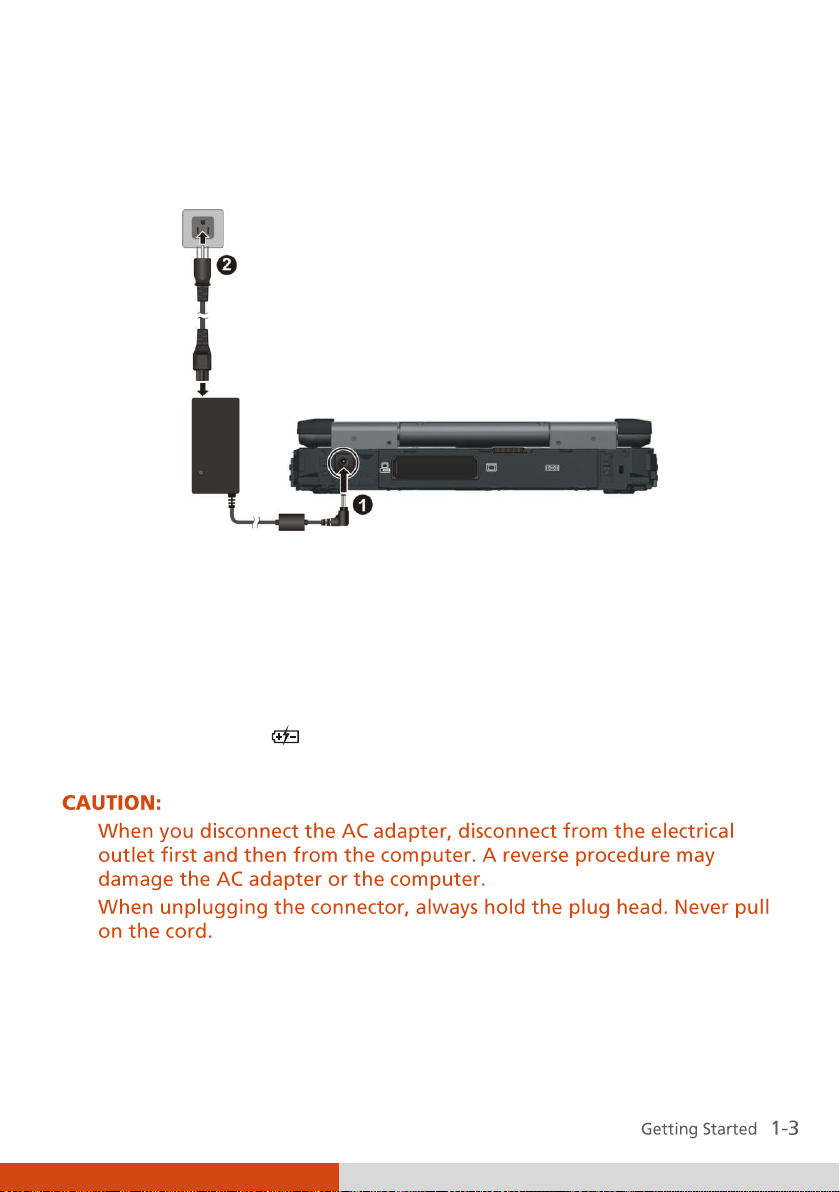
3. Plug the female end of the AC power cord to the AC adapter and the
male end to an electrical outlet ().
4. When the AC adapter is connected, power is being supplied from the
electrical outlet to the AC adapter and onto your computer. Now, you
are ready to turn on the computer.
5. When the AC adapter is connected, it also charges the battery pack. The
Battery Charge Indicator on the computer glows amber to indicate that
charging is in progress. When the battery is fully charged, the Battery
Charge Indicator ( ) glows green. (For information on using battery
power, see Chapter 3.)
Page 14
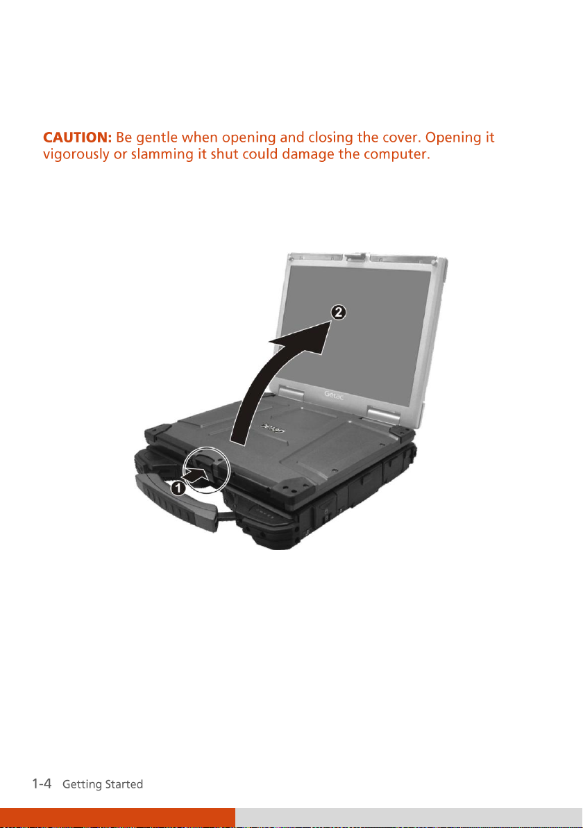
Opening the Cover
Open the top cover by pushing on the cover latch () and lifting up the
cover (). You can tilt the cover forward or backward for optimal viewing
clarity.
Page 15
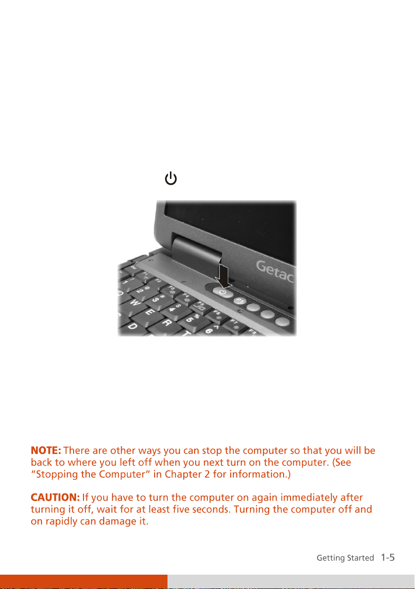
Turning On and Off the Computer
Turning On
1. Make sure that the computer is connected to AC power or battery is fully
charged.
2. Open the top cover
3. Press the power button (
4. Each time the computer is turned on, it performs a Power-On Self Test
(POST), and the operating system such as Windows should start.
).
Turning Off
To turn off the computer power, use the “Shut Down” command of your
operating system.
Page 16
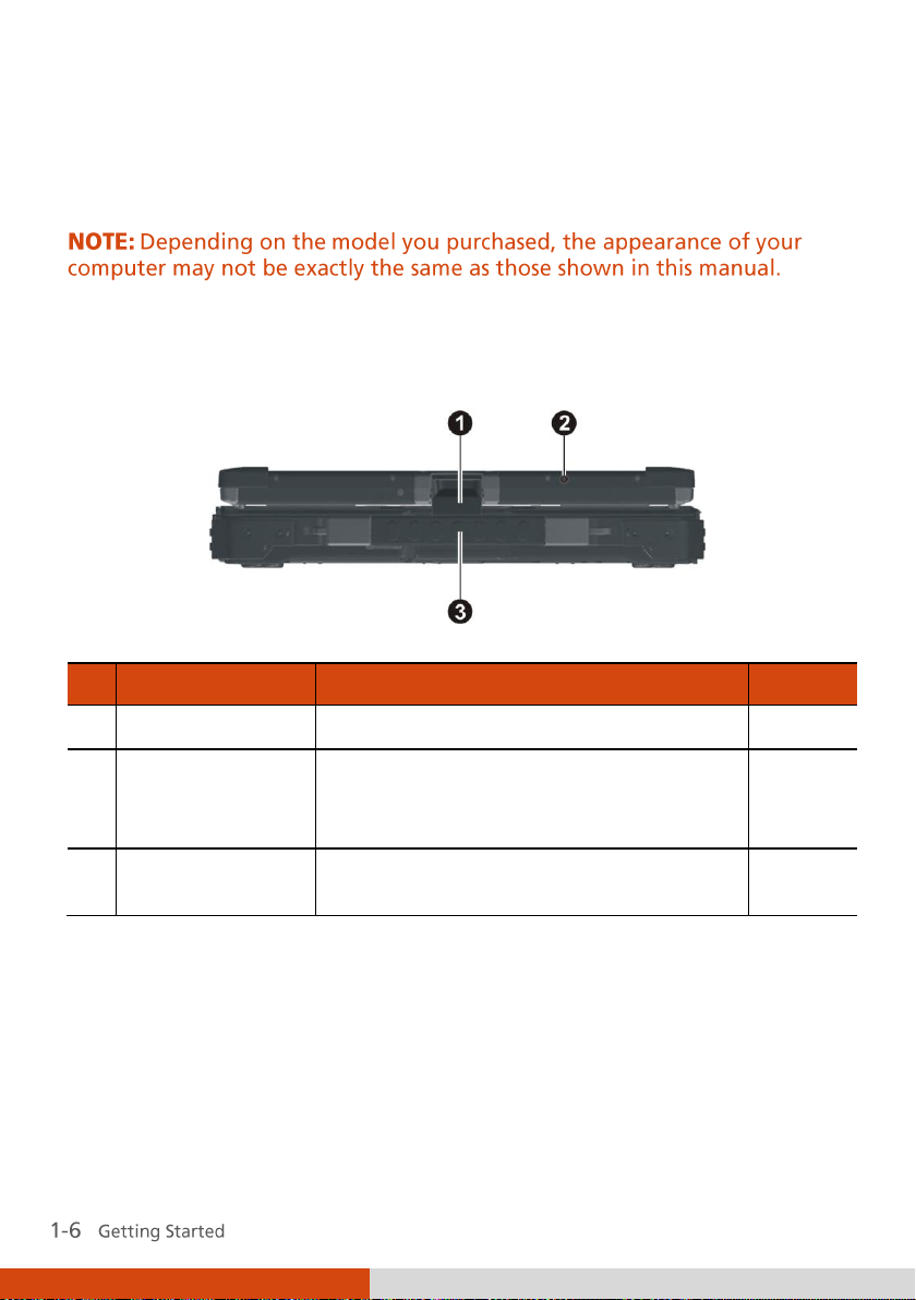
Ref
Component
Description
See Also
Top Cover Latch
Locks the top cover.
P. 1-4
3G Antenna
Serves as the antenna for wireless
modem.
NOTE: For data transmission only.
P. 2-34
Handle
Provides a convenient way to carry the
computer anywhere.
Taking a Look at the Computer
Front Components
Page 17
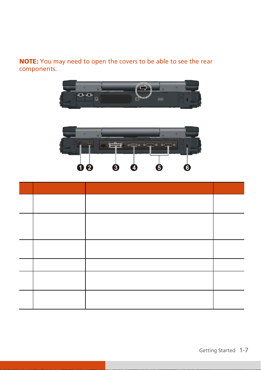
Ref
Component
Description
See Also
Power
Connector
Connects the AC adapter.
P. 1-2
USB Port
Connects a USB device, such as a USB flash
disk, printer, digital camera, joystick, and
more.
P. 4-5
Expansion Bus
Connector
Connects to a Port Replicator.
P. 4-14
VGA Connector
Connects an external display monitor.
P. 4-2
Serial
Connector
Connects a serial mouse or serial
communication device.
P. 4-4
Kensington
Lock
Locks the computer to a stationary object
for security.
P. 7-3
Rear Components
Page 18
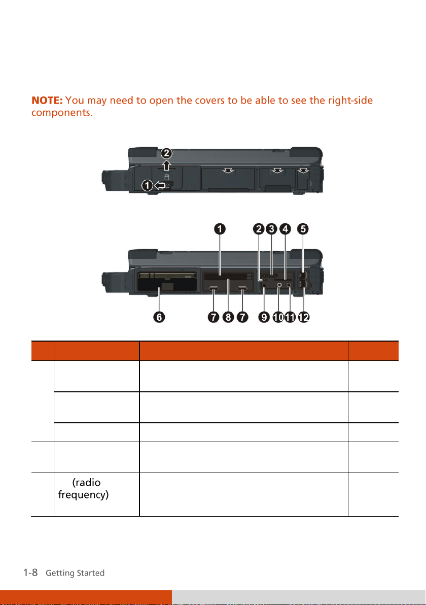
Ref
Component
Description
See Also
Expansion Card
Slot
Depending on your model, the expansion
card slot can be any of the following:
ExpressCard
Slot
Accepts an ExpressCard/34 or
ExpressCard/54 for additional functions.
P. 4-10
PCMCIA Slot
Accepts a PC card for additional functions.
P. 4-8
Mini IEEE 1394
Port
Connects an IEEE 1394 device such as a
scanner, printer, DVCAM, VCR, and more.
P. 4-6
RF
On/Off Switch
Serves as the master control that turns the
wireless LAN radio,
Bluetooth
radio, and
WWAN on/off.
P. 2-27,
2-29,
2-34
Right-Side Components
Page 19
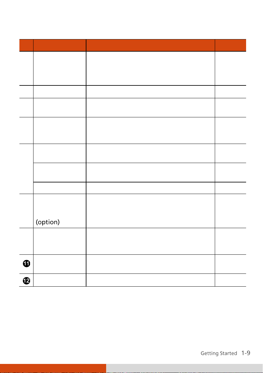
Ref
Component
Description
See Also
Card Reader
Accepts a MultiMediaCard (MMC), Secure
Digital (SD), Memory Stick (MS) or
Memory Stick PRO (MS PRO) card for
removable storage media.
P. 4-12
RJ-11 Connector
Connects the telephone line.
P. 2-24
Hard Disk Drive
Compartment
Inside is the hard disk drive.
P. 2-16
USB Ports
Each of the two ports connects a USB
device, such as a USB flash disk, printer,
digital camera, joystick, and more.
P. 4-5
Expansion Card
Slot
Depending on your model, the expansion
card slot can be any of the following:
Smart Card
Reader
Accepts a smart card for additional
security feature.
P. 4-7
PCMCIA Slot
Accepts a PC card for additional functions.
P. 4-8
GPS Antenna
pass-through
Connector
Connects to the optional antenna for GPS
receiver. (You need to install third-party
GPS navigation software to take
advantage of the GPS feature.)
Audio Output
Connector
Connects a set of headphones, external
speakers with amplifier, or an audio
recording device.
P. 2-23
Microphone
Connector
Connects an external microphone.
P. 2-23
RJ-45 Connector
Connects the LAN cable.
P. 2-25
Page 20

Ref
Component
Description
See Also
Battery Pack
Supplies power to your computer when
external power is not connected.
P. 3-3
Media Bay
Depending on your model, the media bay
may contain any of the following:
Combo Drive/
DVD Dual Drive/
Super Multi
Drive
Accepts a compact disc for installing or
loading software, accessing data, and
playing music/video.
P. 2-18
Secondary
Battery Pack
Supplies power to your computer when
external power is not connected.
P. 3-7
Secondary Hard
Disk Drive
Inside is the hard disk drive.
P. 2-16
Left-Side Components
Page 21
Ref
Component
Description
See Also
Memory Slots
Inside are the memory slots for expanding
the memory size of your computer.
P. 4-15
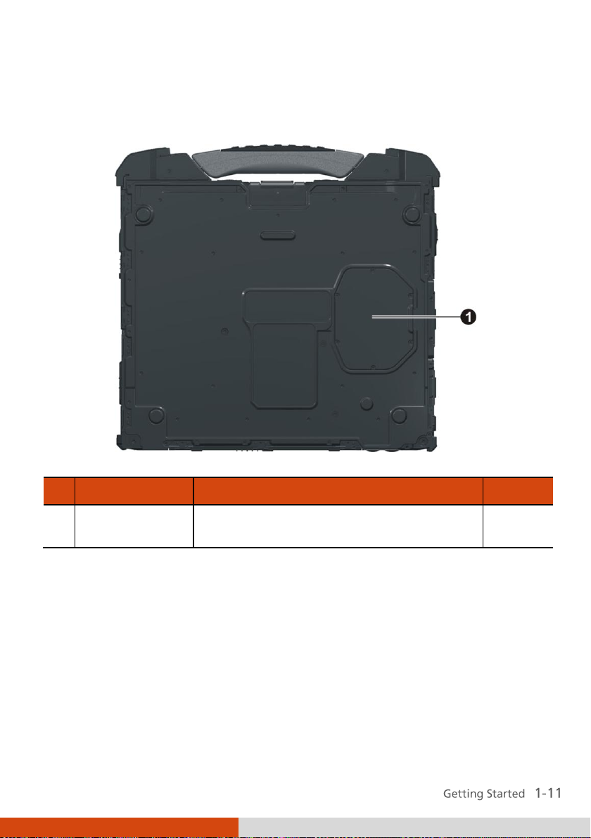
Bottom Components
Page 22
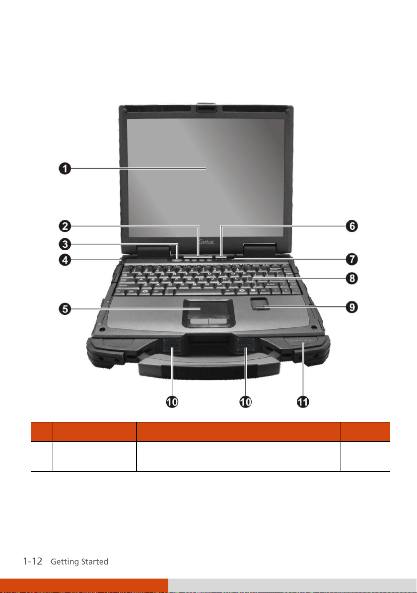
Ref
Component
Description
See Also
LCD Screen
Displays the output of the computer. May
include the optional touchscreen feature.
P. 2-21
Top-open Components
Page 23
Ref
Component
Description
See Also
Quick Buttons
P1
Turns off/on the LCD display and LED
indicators, or
User customized program quick launch
key.
NOTE: The function of P1 quick button
depends on your setting in BIOS Setup
program under the Advanced menu (see
chapter 5 for details).
P. 2-14
P. 6-3
Enables/disables power saving when using
battery power.
P. 2-14
Lights green when power saving mode is
ON.
Enables/disables sunlight readable display.
P. 2-14
Lights green when sunlight readable
mode is ON.
Enables/disables light sensor.
P. 2-14
Lights green when light sensor is ON.
Power Button
Turns the computer power ON and OFF.
P. 1-5
Touchscreen
Pen
Provides a convenient way to use the
touchscreen. Can be stretched for better
grip and handling.
P. 2-12
Touchpad
Serves as the pointing device of the
computer.
P. 2-9
Indicators
Show the current status of the computer’s
devices.
Hard Disk Drive
/ Optical Drive
Blinks green when computer is reading /
writing data to the hard disk or optical
drive.
P. 2-16
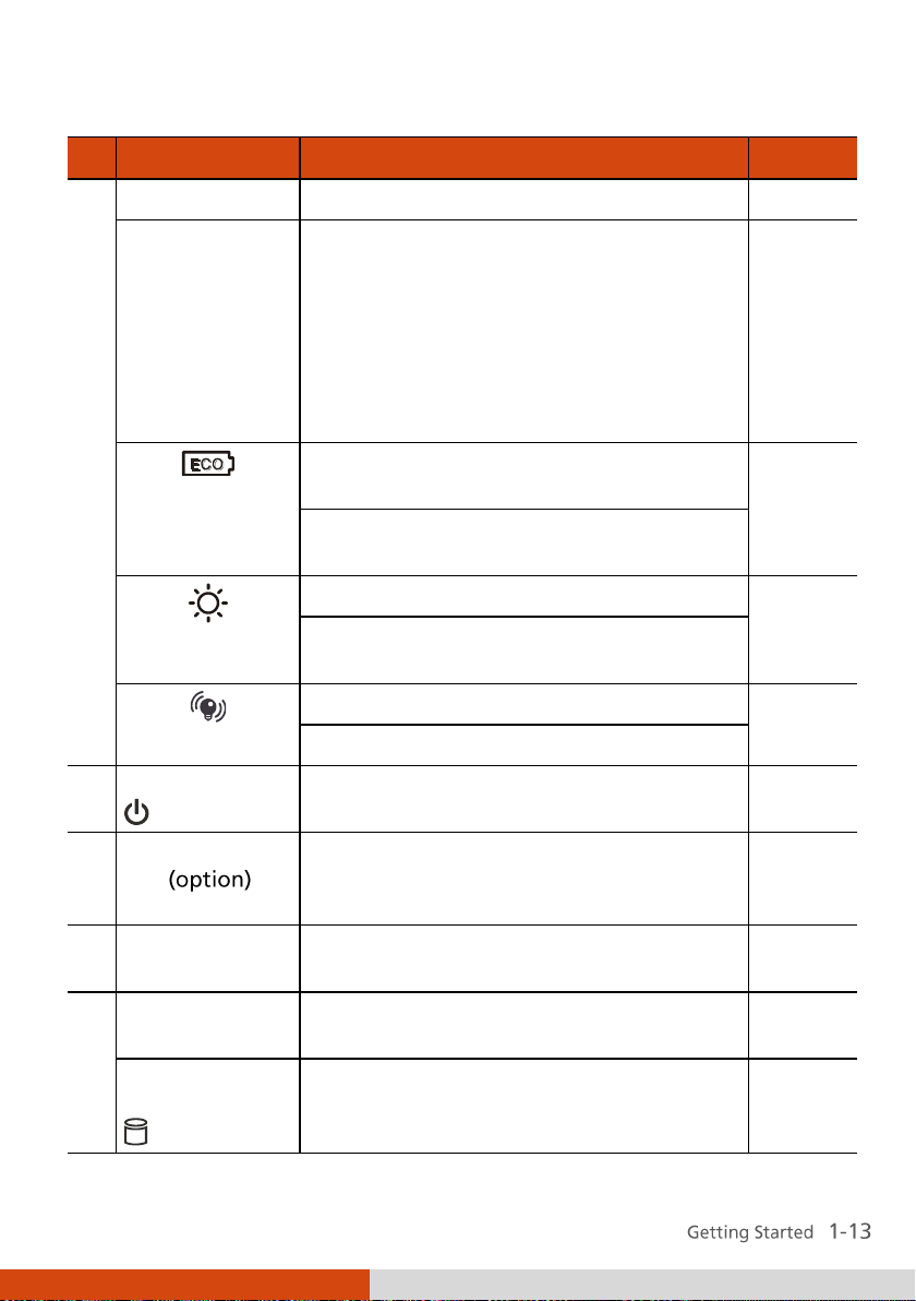
Page 24
Ref
Component
Description
See Also
Card Reader
Blinks green when computer is reading /
writing data to the storage card.
P. 4-12
Caps Lock
Lights green when Caps Lock is on.
P. 2-5
Num Lock / HDD
Heater
Lights green when Num Lock is on.
P. 2-27
Lights amber when optional hard disk
heater is on (temperature is lower than
5oC when booting your computer).
Microphone
Receives sound and voice for the
computer.
P. 2-22
Keyboard
Serves as the data input device of the
computer.
P.2-4
Fingerprint
Sensor
Serves as the fingerprint verification,
preventing unauthorized access to your
computer.
P. 2-38
Stereo Speaker
Sends out sound and voice from the
computer.
P. 2-22
Indicators
Show the current status of the computer’s
devices.
Power
Lights green when computer is on.
P. 1-5
Blinks green when computer is on Sleep
mode.
Battery Charge
Lights green when the battery is fully
charged.
P. 3-3
Lights amber when the battery is being
charged.
Blinks red when the battery’s capacity is
below 10 %.
Blinks amber when the battery is in an
abnormal condition.
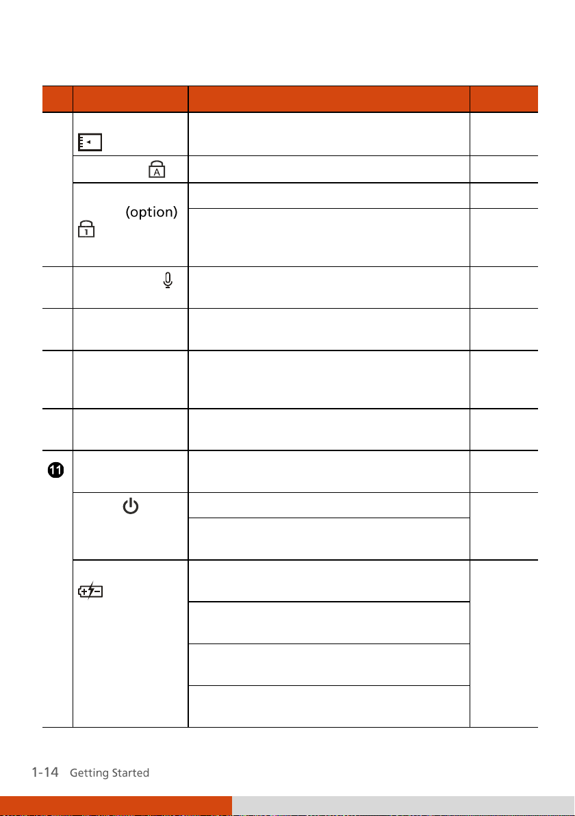
Page 25
Ref
Component
Description
See Also
WLAN
Lights green when WLAN is on.
P. 2-27
Bluetooth
Lights green when Bluetooth is on.
P. 2-29
3G
Lights green when 3G is on.
P. 2-34
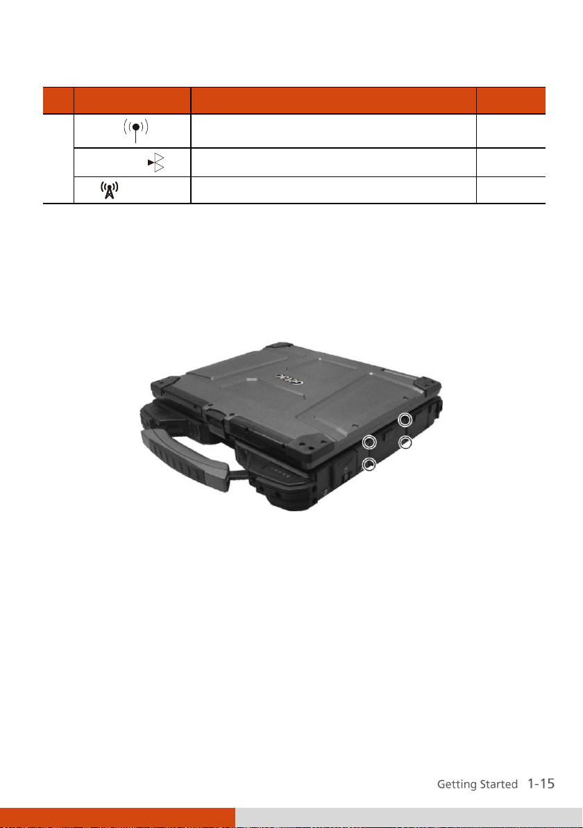
Closing Connector Covers
It is important to close the connector covers completely to ensure the
waterproof integrity. When closing the covers, push the four corners and
make sure that the cover fits in completely.
Page 26

Page 27

Chapter 2
Operating Your
Computer
This chapter provides information about the use of the computer.
If you are new to computers, reading this chapter will help you learn the
operating basics. If you are already a computer user, you may choose to read
only the parts containing information unique to your computer.
Page 28
To stop in
this mode...
Do this...
To start up or
resume again
Off
Click Start Shut Down … This can
prevent loss of unsaved data or damage
to your software programs.
If the system is locked up because of
hardware or software problems, press the
power button to turn off the computer.
Press the power
button.
Sleep
Depending on your settings in Windows,
you can place the computer in Sleep
mode by:
Closing the display cover
Press any key.
Starting and Stopping the
Computer
There are a number of ways to start and stop the computer.
Starting the Computer
You always start the computer using the power button.
A computer starts up with an operating system (OS) existing on the storage
device such as the hard disk. The computer will automatically load the OS
after you turn it on. This process is called booting.
Stopping the Computer
When you finish a working session, you can stop the computer by turning
off the power or leaving the computer in Sleep or Hibernation mode:
Page 29

To stop in
this mode...
Do this...
To start up or
resume again
Pressing the Fn+F12 hot key
Pressing the power button
Hibernation
Depending on your settings in Windows,
you can place the computer in
Hibernation mode by:
Closing the display cover
Pressing the Fn+F12 hot key
Pressing the power button
Press the power
button.
If you choose to stop in Sleep or Hibernation mode, you can return to where
you left off the next time you start up the computer. (See “Power
Management” in Chapter 3 for more information.)
Page 30

Using the Internal Keyboard
Your keyboard has all the standard functions of a full-sized computer
keyboard plus an Fn key added for specific functions.
The standard functions of the keyboard can be further divided into four
major categories:
Typewriter keys
Cursor-control keys
Numeric keys
Function keys
Typewriter Keys
Typewriter keys are similar to the keys on a typewriter. Several keys are
added such as the Ctrl, Alt, Esc, and lock keys for special purposes. When the
lock keys ( aps Lock and Num Lk) are pressed, their corresponding indicators
light up.
The Control (Ctrl) / Alternate (Alt) key is normally used in combination with
other keys for program-specific functions. The Escape (Esc) key is usually
used for stopping a process. Examples are exiting a program and canceling a
command. The function depends on the program you are using.
Cursor-Control Keys
Page 31

Numeric Keypad
A 15-key numeric keypad is embedded in the typewriter keys as shown next:
Numeric keys facilitate entering of numbers and calculations. When Num
Lock is on, the numeric keys are activated; meaning you can use these keys
to enter numerals.
Fn
Page 32

Key
Description
Switches the wireless LAN radio on and off.
Switches the night vision feature on and off for
viewing the display when using night vision goggles
(optional).
Decreases the sound volume.
Increases the sound volume.
Function Keys
On the top row of the keys are the function keys: F1 to F12. Function keys
are multi-purpose keys that perform functions defined by individual
programs.
Fn Key
The Fn key, at the lower left corner of the keyboard, is used with another
key to perform the alternative function of a key. The letter “Fn” and the
alternative functions are identified by the color of blue on the keytop. To
perform a desired function, first press and hold Fn, then press the other key.
Hot Keys
Hot keys refer to a combination of keys that can be pressed any time to
activate special functions of the computer. Most hot keys operate in a cyclic
way. Each time a hot key combination is pressed, it shifts the corresponding
function to the other or next choice.
You can easily identify the hot keys with the icons imprinted on the keytop.
The hot keys are described next.
Page 33

Key
Description
Switches the display output to one of the following
when external devices are connected.
Upon booting the system with CRT:
LCD CRT
LCD & CRT
NOTE: This function only applies to Plug & Play display
devices.
Decreases the LCD brightness.
Increases the LCD brightness.
Switches the touchscreen on and off (option).
Switches the touchpad off and on.
Switches the system sound output off (mute) and on.
Switches the display on and off.
Serves as the sleep button that you can define with
Windows’ Power Options. (See the “Power
Management” in Chapter 3.)
Switches the keyboard backlight on and off (option).
Page 34

Euro Symbol
You can press the euro dollar sign on various keyboards.
To press the euro sign on a United States-International keyboard, hold
down the Alt Gr key and press 5 (which has an euro sign on it).
To press the euro sign on a standard United States keyboard, hold down
either of the Alt keys and type 0128 on the numeric keypad part of your
keyboard.
To press the euro sign on an UK keyboard, hold down the Alt Gr key and
press 4 (which has an euro sign on it).
Windows Keys
The keyboard has two keys that perform Windows-specific functions:
Windows Logo key and Application key.
The Windows Logo key opens the Start menu and performs
software-specific functions when used in combination with other keys. The
Application key usually has the same effect as a right mouse click. (See
your Windows manual for more information.)
Page 35

Using the Touchpad
Fn+F9
The touchpad is a pointing device that allows you to communicate with the
computer by controlling the location of the pointer on the screen and
making selection with the buttons.
The touchpad consists of a rectangular pad (work surface) and a left and
right buttons. To use the touchpad, place your forefinger or thumb on the
pad. The rectangular pad acts like a miniature duplicate of your display. As
you slide your fingertip across the pad, the pointer (also called cursor) on the
screen moves accordingly. When your finger reaches the edge of the pad,
Page 36

Term
Action
Point
Move your finger on the pad until the cursor points to the
selection on the screen.
Click
Press and release the left button.
–or–
Tap gently anywhere on the pad.
Double-click
Press and release the left button twice in quick succession.
–or–
Tap twice on the pad rapidly.
Drag and
drop
Press and hold the left button, then move your finger until
you reach your destination (drag). Finally, release the
button (drop) when you finish dragging your selection to
the destination. The object will drop into the new location.
–or–
Gently tap twice on the pad and on the second tap, keep
your finger in contact with the pad. Then, move your
finger across the pad to drag the selected object to your
destination. When you lift your finger from the pad, the
selected object will drop into place.
simply relocate yourself by lifting the finger and placing it on the other side
of the pad.
Here are some common terms that you should know when using the
touchpad:
Page 37

Term
Action
Scroll
To scroll is to move up and down or left and right in the
working area on the screen.
To move vertically, place your finger on the right or left
edge of the pad and slide your finger up and down along
the edge. To move horizontally, place your finger on the
top or bottom edge of the pad and slide your finger left
and right.
This function works only after you install the touchpad
driver supplied with the computer and it may not work for
all applications.
TABLE NOTE: If you swap the left and right buttons, “tapping” on the
touchpad as an alternative method of pressing the left button will no longer
be valid.
Configuring the Touchpad
You may want to configure the touchpad to suit your needs. For example, if
you are a left-handed user, you can swap the two buttons so that you can
use the right button as the left button and vice versa. You can also change
the size of the on-screen pointer, the speed of the pointer, and so on.
To configure the touchpad, go to Control Panel Hardware and Sounds
Mouse Properties.
Page 38

Using the Touchscreen (Optional)
Fn+F8
The touchscreen is a touch-sensitive device that allows you to easily use the
computer without a mouse or touchpad.
Page 39

Term
Action
Click/Point
Tap gently on the touchscreen.
Double-click
Tap twice on the touchscreen rapidly.
Drag and drop
Press lightly on the touchscreen and move your finger
until you reach your destination (drag). Finally, release
your finger (drop) when you finish dragging your
selection to the destination. The object will drop into the
new location.
Here are some common terms that you should know when using the
touchscreen:
Page 40

Using the Quick Buttons
Located on top of the keyboard are four quick buttons:
LCD display and LED indicators quick button (P1) to turn off the LCD
display and LED indicator, or
User customized program quick launch key (P1) – see chapter 6 for more
details.
P1
Advanced
Power saving quick button (
when using battery power. The system will turn down the panel
backlight and sacrifice processing speed to gain more battery life.
Lights green when power saving mode is enabled.
Sunlight readable quick button ( ) for enabling the sunlight readable
LCD display.
Lights green when sunlight readable mode is enabled.
) to enter into power saving mode
Page 41

Light sensor quick button ( ) for adjusting the LCD brightness
automatically based on your computer’s surrounding lighting condition.
Lights green when light sensor is enabled.
Page 42
Using the Hard Disk Drive
Your computer comes with a removable hard disk drive as drive C. A hard
disk drive is a storage device with non-removable, rotating, magnetic
storage platters inside it. It is where your operating system and application
software programs are stored.
Your hard disk drive is a 2.5-inch PATA (parallel ATA) / SATA (serial ATA)
hard disk drive. This type of drive embodies the latest in fast, reliable mass
storage by integrating all the control circuitry necessary for operation
directly onto the drive itself.
The system may come with an optional heater that automatically turns on
for low temperature operation.
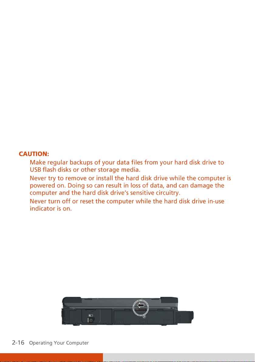
Installing a Second Hard Disk Drive
(Optional)
You can install a second hard disk drive to your computer. To install a second
hard disk drive:
1. Make sure that system power is off.
2. Open the media bay cover by sliding the release latch towards the left.
Page 43

3. Press upward the optical drive release latch () and carefully pull on the
ribbon strip () to remove the optical drive.
4. Be careful to observe the correct orientation and slide the hard disk drive
bracket into the media bay until it reaches the end.
5. Close the media bay cover to secure the hard disk drive bracket.
Page 44

Using the Optical Drive (Optional)
Your computer may come with an optical drive, usually configured as drive
D.
Depending on the model, your drive is one of the following:
Combo drive can work both as a DVD drive (reading DVD discs in
addition to CDs, audio CDs and CD-R/-RW discs), and also as a CD
recorder (writing to CD-R/-RW discs).
DVD Dual drive besides the Combo drive function, can write to
DVD+R/+RW/-R/-RW discs.
Super Multi drive besides the Combo drive function, can write to
DVD+R/+RW/-R/-RW and DVD-RAM discs.
Page 45

Inserting and Removing a Disc
Follow this procedure to insert or remove a disc:
1. Turn on the computer.
2. Open the media bay cover by sliding the release latch towards the left.
3. Press the eject button and the DVD tray will slide out partially. Gently
pull on it until it is fully extended.
4. To insert a disc, place down the disc in the tray with its label facing up.
Slightly press the center of the disc until it clicks into place.
To remove a disc, hold the disc by its outer edge and lift it up from the
tray.
Page 46
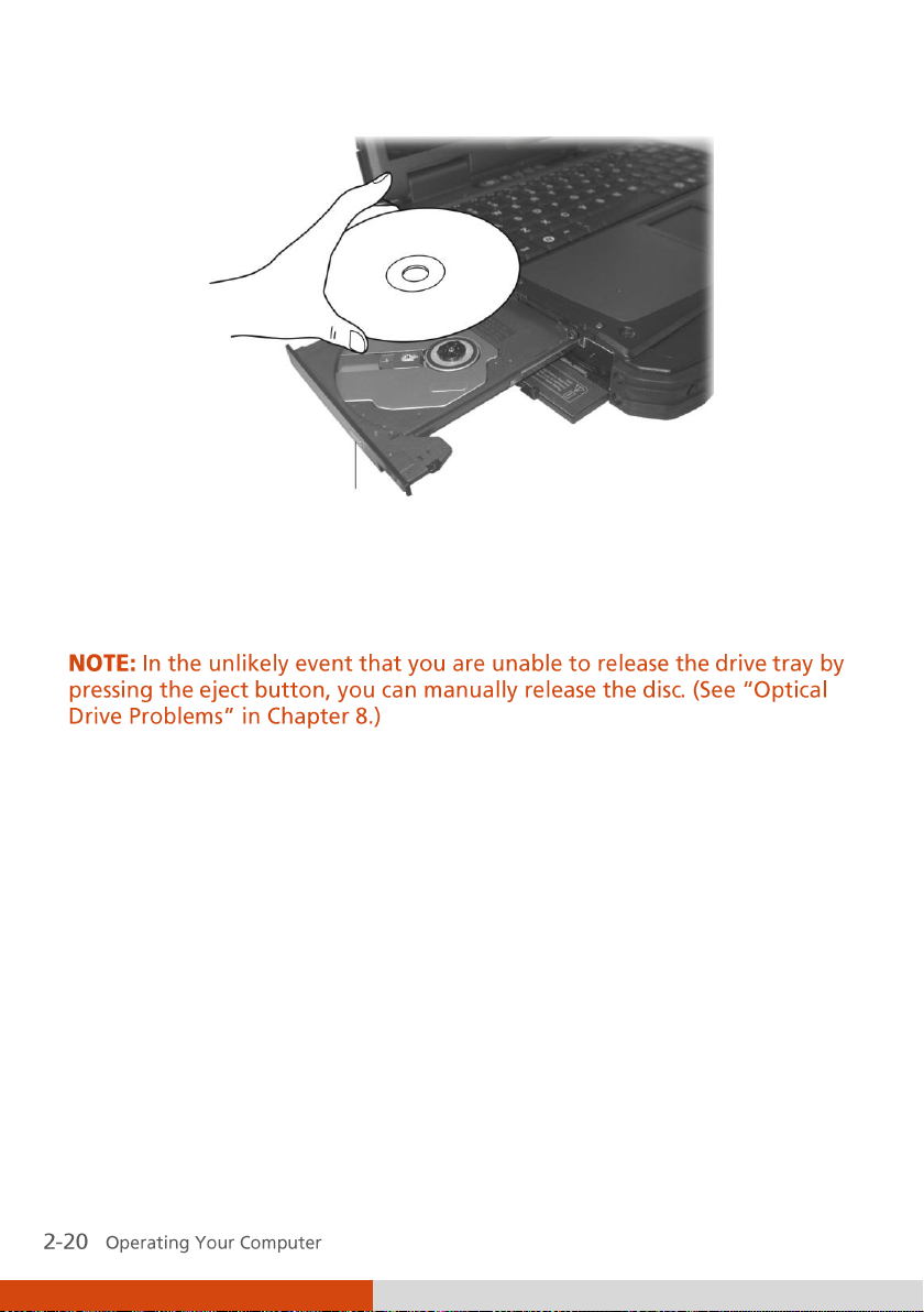
Eject button
5. Gently push the tray back into the drive.
6. Close the media bay cover.
Page 47
Using the Video Features
The video subsystem of your computer features:
13.3-inch wide TFT (Thin-Film Transistor) color LCD display with
1024×768 XGA resolution
Multi-display capability, which allows you to expand your desktop on the
screen to another display device so that you have more desktop space to
work on
Sunlight-readable LCD display by pressing sunlight readable quick
button ( )
Automatically adjust the LCD brightness by pressing light sensor quick
button ( )
Optional night vision display by pressing Fn + F2
Power Management
Power Options System
Settings
Configuring the Display Modes
Your computer has been set to a default resolution and number of colors
before shipment. You can view and change display settings through your
operating system. See your operating system documentation or online help
for specific information.
For displaying in higher resolutions, you can connect an external monitor
that supports higher resolutions. (See “Connecting an External Monitor” in
Chapter 4 for more information.)
Page 48

Using the Audio Features
The audio subsystem of your computer features:
Azalia interface (high density audio codec)
2-channel analog output
Built-in microphone ()
External audio connectors () and
Set of speakers ()
Ways of playing and recording sound vary with the operating system used.
See your operating system documentation or online help for specific
information.
Page 49

Connecting Audio Devices
For higher audio quality, you can send or receive sound through external
audio devices.
Audio Output Connector (green) can be connected to speakers,
headphones, or earphone set.
Microphone Connector (pink) can be connected to an external
microphone for recording voice or sound.
Page 50

Using the Communication
Features
Using the Modem
The internal 56 K fax/data modem allows you to use the telephone line to
communicate with others by fax, email, or connect to an online service or
bulletin board.
To connect the telephone line to the modem, connect one end of the
modem cable to the RJ-11 connector on the computer and the other end to
the phone line.
Page 51

Using the LAN
The internal 10/100/1000Base-T LAN (Local Area Network) module allows
you to connect your computer to a network. It supports data transfer rate up
to 1000 Mbps.
To connect the network cable to the LAN module, connect one end of the
LAN cable to the RJ-45 connector on the computer and the other end to the
network hub.
Page 52

Technology
Stated
Maximum
Throughput
(Mbps)
Data Rates
(Mbps)
Band
(GHz)
Modulation
Technology
802.11a
54
54, 48, 36,
24, 18, 12,
9, 6
5.15 ~
5.35
OFDM (Orthogonal
Frequency Division
Multiplexing)
802.11b
11
11, 5.5, 2, 1
2.412 ~
2.462
DSSS (Direct
Sequence Spread
Spectrum)
802.11g
54
54, 36, 18, 9
2.4
OFDM (Orthogonal
Frequency Division
Multiplexing)
802.11n
100 Mbps
or more
100 ~ 210
2.4 / 5
Spatial multiplexing,
uses MIMO
(multiple-input
multiple-output)
Using the Wireless LAN
Depending on your model, an internal mini PCI-E wireless LAN (WLAN) card
may have been pre-installed by your computer manufacturer at the factory.
This card allows you to access corporate networks or the Internet in a
wireless environment.
The WLAN features include:
Peer-to-Peer (Ad-Hoc) and Access Point (Infrastructure) modes support
WEP (Wired Equivalent Privacy) 64/128-bit data encryption
IEEE 802.11a/b/g/n standard compliance
If your WLAN card was provided by your dealer instead of the computer
manufacturer, contact your dealer for the correct driver to use.
Page 53

Turning Off/On the WLAN Radio
To turn on the WLAN radio:
1. Make sure that the RF switch is at the ON position.
2. Press Fn+F1 to turn on the WLAN radio (see “Hot Keys” in Chapter 2),
indicated by the WLAN indicator ( ) glowing in green when on.
If you need to temporarily turn off the radio, press Fn+F1. To resume
network connection, press Fn+F1 again.
It takes approximately 30 seconds for your computer to make a successful
WLAN connection and approximately 10 seconds to disconnect.
Connecting to a Wireless Network
To connect to a wireless network:
1. Make sure that the WLAN radio is on (see the previous section).
2. Right-click the Wireless Network Connection icon
Windows system tray and select Connect to a network.
3. If any wireless network is detected, the following window appears on
screen. Click the Show drop down menu and select Wireless.
located on the
Page 54

4. Select a wireless network to connect to by clicking a selection, then click
Connect.
5. Depending on the settings, you may be asked to enter a WEP key (refer
to your Windows online help for more information on setting a wireless
network connection).
Page 55

Using the
Depending on your model, your computer may incorporate the
capability for short-range (about 10 meters) wireless communications
between devices without requiring a cable connection.
With
Bluetooth
pockets and briefcases as long as two devices are within range.
Bluetooth
wireless technology, data can be transmitted through walls,
Turning On and Off the
1. Make sure that the RF switch is at the ON position.
2. Right-click the GETAC Utility icon ( ) located on Windows system tray
and select Quick Bar.
®
Feature
Bluetooth
Feature
Bluetooth
3. The following appears onscreen. To turn on the Bluetooth feature, click
the Bluetooth quick button.
Page 56

Status
Icon
Off
(blue with red logo)
On
(blue with white logo).
Connected
(blue with green logo)
The Bluetooth indicator ( ) will glow in green. By default, your
computer is in the general discoverable and pairable mode after the
Bluetooth feature is turned on.
4. To turn off the Bluetooth feature, click the Bluetooth quick button
again.
The status of the
located in the system tray in the lower-right part of the screen.
You can use the
settings and transfer files.
Connecting to another
1. Make sure that the target
and within close range. (See the documentation that came with the
Bluetooth
2. Right-click the icon, and then click Add New Connection.
Bluetooth
Bluetooth
device.)
connection is indicated by the
Utility to configure
Bluetooth
Bluetooth
Bluetooth
Device
device is turned on, discoverable
Bluetooth
wireless connection
icon
Page 57

3. The Add New Connection Wizard window appears. Select Express Mode
(Recommended), and then click Next.
4. Select the device to connect to and click Next.
Page 58

5. Depending on the type of
you will need to enter the pertinent information.
Bluetooth
device that you want to connect to,
Sending a File
1. Make sure that the target
and within close range. (See the documentation that came with the
Bluetooth
2. Right-click the icon, and then click Wireless File Transfer.
device.)
Bluetooth
device is turned on, discoverable
Page 59

3. In the Wireless File Transfer window, click Add to browse for the file to
send.
4. Click the target device from the list, and then click Send to start the
transfer procedure.
Page 60

Using the 3G Feature (Optional)
3G is the third generation of mobile phone standards and technology, after
2G. It is based on the International Telecommunication Union (ITU) family of
standards under the International Mobile Telecommunications programme.
Unlike IEEE 802.11 networks, 3G networks are
networks
primarily developed for data.
. IEEE 802.11 networks are short range, high-bandwidth networks
wide area cellular telephone
Page 61

Installing a SIM Card
To use the 3G feature (GSM/UMTS/EDGE/GPRS/EVDO/HSUPA) on your
computer, you need to subscribe to 3G service and install the 3G SIM card
from your service provider, network operator, or other vendor.
To install the SIM card, follow these steps:
1. Make sure that the computer is not turned on or connected to AC
power.
2. Open the media bay cover by sliding the release latch towards the left.
3. Press upward the optical drive release latch () and carefully pull on the
ribbon strip () to remove the optical drive from the media bay.
4. Carefully place your computer upside down and locate the SIM card slot.
Page 62

5. Insert the SIM card into the holder. Make sure the beveled corner on the
SIM card is facing towards the slot and that the golden contact area on
the card is facing downwards.
6. Replace the optical drive.
7. Close the media bay cover to secure the optical drive in place.
Page 63

Turning On and Off the 3G Feature
1. Make sure that the RF switch is at the ON position.
2. Right-click the GETAC Utility icon ( ) located on Windows system tray
and select Quick Bar.
3. The following appears onscreen. To turn on the 3G feature, click the 3G
quick button.
The 3G indicator ( ) will glow in green.
4. To turn off the 3G feature, click the 3G quick button again.
You can use the 3G software application to configure 3G connection
settings.
Page 64

Using the Fingerprint Sensor
To start using the fingerprint sensor:
1. Locate and slide open the fingerprint sensor cover.
2. Go to Start menu Programs Protector Suite QL Control Center.
The following screen appears.
Page 65

The computer features the Fingerprint Control Center utility for enrolling
your fingers for added security. It contains the following:
Fingerprints – for enrolling or editing fingerprint templates
Settings – for configuring the fingerprint software
Help – for browsing the Fingerprint Control Center online Help
Start Programs Protector Suite QL Help
Page 66

Enrolling Fingerprints
To start enrolling your fingerprint(s):
1. Click Fingerprints on the main screen.
2. Click Initialize.
3. The following screen appears. Read carefully the contents of the
Welcome screen and then click Next to continue.
Page 67

4. Follow the onscreen instructions to complete enrolling your
fingerprint(s).
Page 68

Changing the Settings
To change the settings of your fingerprint software:
1. Click Settings on the main screen.
2. Click System Settings.
3. The following screen appears. Proceed to make the necessary settings to
your fingerprint software.
Page 69

4. Click OK after you have finished with your settings.
Page 70

Page 71

Chapter 3
Managing Power
Your computer operates either on external AC power or on internal battery
power.
This chapter tells you how you can effectively manage power. To maintain
optimal battery performance, it is important that you use the battery in the
proper way.
Page 72

AC Adapter
The AC adapter serves as a converter from AC (Alternating Current) to DC
(Direct Current) power because your computer runs on DC power, but an
electrical outlet usually provides AC power. It also charges the battery pack
when connected to AC power.
The adapter operates on any voltage in the range of 100~240 V AC.
Page 73

Battery Pack
The battery pack is the internal power source for the computer. It is
rechargeable using the AC adapter.
The operating time of a fully charged battery pack depends on how you are
using the computer. When your applications often access peripherals, you
will experience a shorter operating time.
Charging the Battery Pack
To charge the battery pack, connect the AC adapter to the computer and an
electrical outlet. The Battery Charge Indicator ( ) on the computer glows
amber to indicate that charging is in progress. You are advised to keep the
computer power off while the battery is being charged. When the battery is
fully charged, the Battery Charge Indicator lights green.
Page 74

Battery Type
Charging Time
Computer is Off
Computer is On and
in Idle State
6-cell (4 A)
2.5~3.5 hours
3.0~4.3 hours
9-cell (4 A)
3.5~4.5 hours
4.0~6.0 hours
The charging times are as follows:
Initializing the Battery Pack
You need to initialize a new battery pack before using it for the first time or
when the actual operating time of a battery pack is much less than expected.
Initializing is the process of fully charging, discharging, and then charging. It
can take several hours.
1. Make sure that the computer power is turned off. Connect the AC
adapter to fully charge the battery pack.
2. After the battery pack is fully charged, turn on the computer. When the
message “Click mouse or press <Enter> for Menu” appears, click
the touchpad’s left button or press the Enter key to invoke the program.
3. A small window appears, select Launch System Setup.
4. Disconnect the AC adapter and leave the computer on until the battery
is fully discharged. The computer will shut down automatically.
5. Connect the AC adapter to fully charge the battery pack.
Page 75

Switch
Checking the Battery Level
By Operating System
You can check the approximate battery level using the battery meter
function of the operating system. To read the battery level in Windows, click
the icon on the system tray.
By Gas Gauge
On the exterior side of the battery pack is a gas gauge for displaying the
estimated battery charge. When the battery pack is not installed in the
computer and you want to know the battery charge, you can press the
switch with a pointed device to see the corresponding value of indicator
segment that light green. The value of the corresponding green segment
indicates the relative percentage of the battery charge. The battery pack is
fully discharged when you see no segment glowing green.
Page 76

Replacing the Battery Pack
If you often rely on battery power for a long period of time while traveling,
you may consider the purchase of an additional battery pack from your
dealer and keep it with you in a fully charged state as a backup.
To replace the battery pack, follow these steps:
1. Make sure that the computer is not turned on or connected to AC
power.
2. Locate the battery compartment on the left side of the computer.
3. Open the compartment cover by sliding the release latch to the left ()
then upwards ().
4. Pull on the ribbon strip to remove the battery pack.
Page 77
5. Slide the new battery pack all the way into the slot. Make sure to
observe the correct orientation (the ribbon strip must face outward for
future battery pack removal).
6. Close the compartment cover and slide the release latch downward, then
towards the right to secure the battery pack.
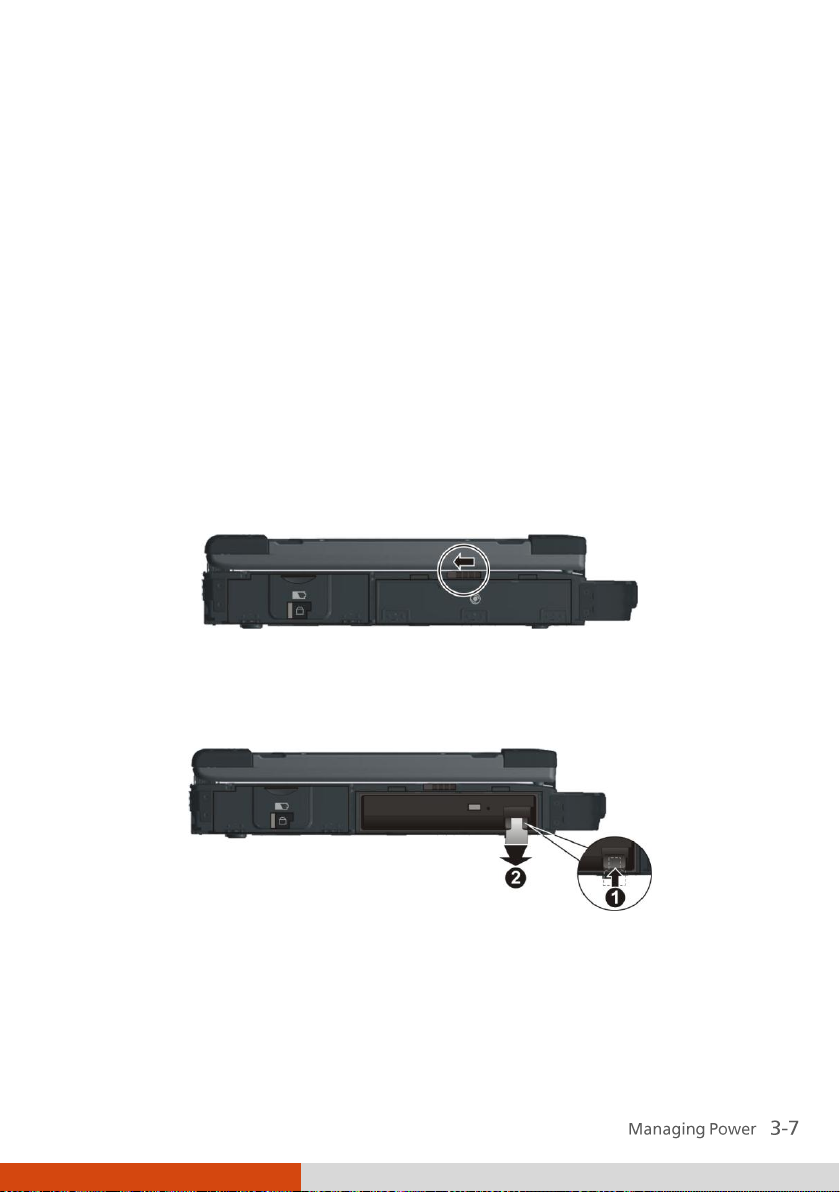
Installing a Second Battery Pack (Optional)
You can install a second battery pack to your computer for a longer
operating time when AC power is not available. To install a second battery
pack:
1. Make sure that system power is off.
2. Open the media bay cover by sliding the release latch towards the left.
3. Press upwards the optical drive release latch () and carefully pull on the
ribbon strip () to remove the optical drive.
Page 78
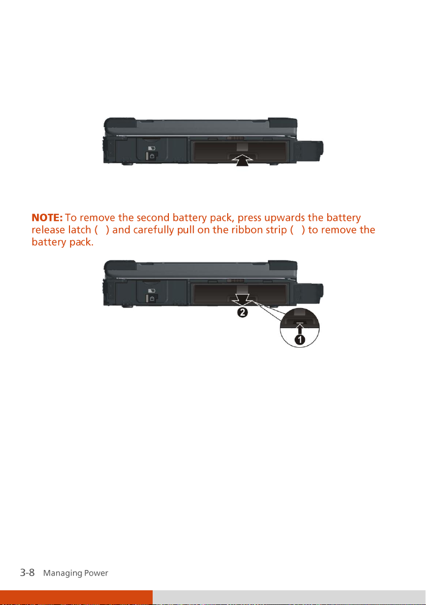
4. Slide the second battery pack all the way into the slot. Make sure to
observe the correct orientation (the ribbon strip must face outward for
future battery pack removal).
5. Close the media bay cover to secure the second battery pack.
On the exterior side of the second battery pack is a gas gauge for displaying
the estimated battery charge. When the battery pack is not installed in the
computer and you want to know the battery charge, you can press the
switch with a pointed device to see the corresponding value of indicator
segment that light green. The value of the corresponding green segment
indicates the relative percentage of the battery charge. The battery pack is
fully discharged when you see no segment glowing green.
Page 79

Switch
Page 80

Battery Low Signals and Actions
The battery icon changes appearance to display the current state of the
battery so that you can see how much charge remains (Windows default
setting). When the battery charge is above 25 % the battery icon is green.
When the battery charge reaches 25 % a yellow triangle with an
exclamation point (!) appears above the green battery icon. When the
charge reaches the low battery level a red circle with a white “X” appears
above the green icon. The computer’s Battery Charge Indicator (
red to alert you to take actions.
Immediately save your data upon Battery Low. The remaining operating
time depends on how you are using the computer. If you are using the audio
subsystem, ExpressCard, hard or USB flash disk, the battery might run out of
charge very quickly.
Always respond to Battery Low by placing your computer on Hibernation
mode, turning off the computer, or connecting the AC adapter.
) blinks
Page 81

What...
When...
Power to the hard disk is turned
off
When the hard disk has been idle for a
set period.
Power to the display is turned off
When the display has been idle for a set
period.
The computer enters the Sleep
mode. The hard disk and display
are turned off and the entire
system consumes less power.
When the entire system has been idle for
a set period.
When you press the Fn+F12 hot key. *
When you close the cover. *
When you press the power button. *
The computer enters the
Hibernation mode. (See the next
subsection for more
information.)
When you press the Fn+F12 hot key. *
When you close the cover. *
When you press the power button. *
Power Management
Your computer supports ACPI (Advanced Configuration and Power
Interface) for power management. The power management feature allows
you to reduce the power consumption for energy saving.
With an ACPI-compliant operating system such as Windows, power supply to
different computer components is controlled on an as-needed basis. This
allows maximum power conservation and performance at the same time.
In general, Windows’ power management works in this way:
* Depends on your settings in Windows.
For detailed information on power management, see Windows’ Help.
Page 82

Hibernation
Power Options System Settings
Control Panel Mobile PC
Hibernation is a very useful feature. People frequently open many
applications when they use computers. It takes some time to get all these
applications open and running, and normally they all have to be closed
before the computer can be turned off.
When you use the hibernation feature, you do not have to close the
applications. The computer stores the state of your computer to a file on the
hard disk and then shuts down. The next time you turn on your computer,
you return to exactly where you left off.
Page 83

Power-Saving Tips
Aside from enabling your computer’s power saving mode (see previous
section), you can do your part to maximize the battery’s operating time by
following these suggestions.
Press the power saving quick button ( ) to enter into power saving
mode when using battery power.
Do not disable Power Management. Choose a Windows power plan that
saves power. A power plan is a collection of hardware and system
settings that control how your computer manages power.
Decrease the LCD brightness to the lowest comfortable level.
Shorten the length of time before Windows turn off the display.
Many USB devices use power just by being connected. If you use a USB
mouse, you can save power by disconnecting the mouse and using the
touchpad. If you use a USB flash drive, unplug it when you are not using
it.
If you work with an application that uses a PC card, exit the application
when you finish using it.
If you have a PC card installed, remove it when not in use. Some PC cards
drain power even while they are inactive.
Deactivate the WLAN function if you are not using it (see Chapter 2).
Deactivate the Bluetooth feature if you are not using it (see Chapter 2).
Turn off the computer when you are not using it.
Page 84

Page 85

Chapter 4
Expanding Your
Computer
You can expand the capabilities of your computer by connecting other
peripheral devices. When using a device, be sure to read the instructions
accompanying the device together with the relevant section in this chapter.
Page 86

Connecting an External Monitor
If you want the benefits of a larger display screen with higher resolution,
you can connect an external display monitor to your computer. Follow this
procedure to connect an external monitor:
1. Make sure that the computer is not turned on.
2. Slide the release latch towards the right to open the connector cover.
3. Plug the monitor’s D-type signal connector to the computer’s VGA
connector.
4. Plug one end of the monitor’s power cord into the power socket on the
monitor and the other end to an electrical outlet.
5. To use the monitor, turn on the monitor before turning on the
computer.
6. The monitor should respond by default. If not, you can switch the display
to the monitor or to both (simultaneous display), or to multi-display by
pressing the Fn+F5 hot key. In Windows, you can also change the display
through the Display Settings Properties.
Page 87

7. You can change display settings through your operating system. See
your operating system documentation or online help for specific
information.
Page 88

Connecting a Serial Device
Your computer has two serial ports for connecting a serial device such as a
serial mouse or serial communication device (modem).
Follow this procedure to connect a serial device:
1. Make sure the “Serial Port COM1/COM2” item is set properly in the BIOS
Setup program. (See “Advanced Menu” in Chapter 5 for information.)
2. Make sure the computer is not turned on
3. Slide the release latch towards the right to open the port cover.
4. Plug the device cable to the serial port on the rear of the computer.
5. Turn on the computer.
Page 89

Connecting a USB Device
Your computer has three USB ports for connecting USB devices, such as a
digital camera, scanner, printer, modem, and mouse.
The USB ports support transfer rates up to 12 MB/s for USB 1.1 devices and
480 MB/s for USB 2.0 devices.
To connect a USB device, slide the release latch towards the right to open
the port cover and then simply plug the device cable to one of the USB ports.
Page 90

Connecting an IEEE 1394 Device
Your computer has a mini IEEE 1394 port for connecting IEEE 1394 devices
that include not only computer peripheral devices such as scanner, printer
and high-quality CCD, but also consumer electronic equipment such as
DVCAM and VCR.
To connect an IEEE 1394 device, prepare an IEEE 1394 cable. Slide the release
latch towards the right to open the connector cover. Then plug the
appropriate end of the cable to the computer’s mini IEEE 1394 connector
and the other end to the device’s corresponding connector.
Page 91

Computer
Chip
Using Smart Cards (Optional)
Depending on the model, your computer has a smart card slot for additional
security feature, providing tamper-proof storage of user and account
identity. A smart card is a type of plastic card embedded with a computer
chip that stores and transacts data between you (user) and the computer.
You need to install third-party smart card software to take advantage of the
smart card feature.
Inserting and Removing a Smart Card
To insert a smart card:
1. Locate the smart card slot on the right of the computer and open the
cover.
2. Slide the smart card, with its label and embedded computer chip facing
down into the slot.
3. When a new card is seated, use the third-party smart card software to
To remove a smart card:
1. Make sure that the third-party smart card software is not accessing the
2. Pull the card out of the slot.
allow your computer to read it.
smart card.
Page 92
Eject button
Using PC Cards
Depending on your model, your computer has one or two PC card slots
which supports type II card and CardBus specifications.
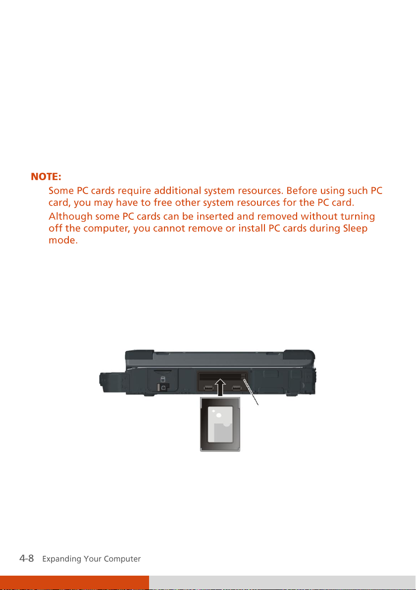
Inserting and Removing a PC Card
To insert a PC card:
1. Locate the PC card slot(s) on the right side of the computer and open the
cover.
2. Slide the PC card, with its label facing up, into the slot until the eject
button pops out.
3. When a new card is seated, the computer will detect it and try to install
the appropriate driver. Follow the on-screen instructions to complete the
process.
Page 93

To remove a PC card:
1. Double-click on the Safely Remove Hardware icon found on the
Windows taskbar and the Safely Remove Hardware window appears on
screen.
2. Select (highlight) the PC card from the list to disable the card.
3. Push the eject button and the card will slide out slightly.
4. Pull the card out of the slot.
Page 94

Using ExpressCards (Optional)
Depending on the model, your computer has an ExpressCard slot.
ExpressCard supports the PCI Express and USB 2.0 serial data interfaces
(supporting speeds of up to 2.5 Gbps and 480 Mbps respectively), improving
speed in data transfer while conserving power usage.
ExpressCard Type
The ExpressCard slot can accommodate a 54 mm (ExpressCard/54) or 34 mm
(ExpressCard/34) wide ExpressCard. Typical ExpressCards support a very
extensive range of applications including memory, wired and wireless
communication cards, and security devices.
Shown next are the appearances of ExpressCards for your reference.
ExpressCard/54 ExpressCard/34
Page 95

Inserting and Removing an ExpressCard
To insert an ExpressCard:
1. Locate the ExpressCard slot on the right side of the computer and open
the cover.
2. Slide the ExpressCard, with its label facing up, all the way into the slot
until the rear connectors click into place.
3. When a new card is seated, the computer will detect it and try to install
the appropriate driver. Follow the on-screen instructions to complete the
process.
To remove an ExpressCard:
1. Double-click on the Safely Remove Hardware icon found on the
Windows taskbar and the Safely Remove Hardware window appears on
screen.
2. Select (highlight) the ExpressCard from the list to disable the card.
3. Push the eject button and the card will slide out slightly.
4. Pull the card out of the slot.
Page 96

Type
MMC Card
SD Card
MS / MS PRO Card
Appearance
Size
24×32× 1.4
(mm)
24×32× 2.1
(mm)
21.5×50×2.8
(mm)
Using the Card Reader
Your computer has a Card Reader. The Card Reader is a small drive for
reading from and writing to removable storage cards (or called memory
cards). The Card Reader supports the MultiMediaCard (MMC), Secure Digital
(SD), Memory Stick (MS), and Memory Stick PRO (MS PRO) cards.
Shown next are the appearance and size of each card type for your
reference.
Page 97

To insert a storage card:
1. Locate the Card Reader slot on the right side of the computer and open
the cover.
2. Align the card with its connector pointing to the slot and its label facing
up. Slide the card into the slot until it reaches the end.
3. Windows will detect the card and assign it a drive name.
To remove a storage card:
1. Double-click My Computer.
2. Right-click the drive with the card and select Eject.
3. Pull the card out of the slot.
Page 98
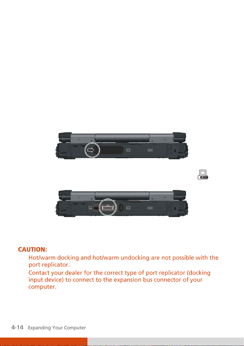
Using the Port Replicator
(Optional)
A port replicator is available as an option. This device eliminates the hassles
of having you connect and disconnect the various cables when carrying your
computer around and allows a variety of peripherals to be connected
including a headphone or microphone, etc. The port replicator connects to
the expansion bus connector at the rear of your computer.
1. Slide open the expansion bus connector cover.
2. Connect your port replicator to the expansion bus connector ( ).
For more detailed information, refer to the Operating Instructions of the
port replicator.
Page 99

System Memory Upgrade
You can upgrade your computer by changing system memory to a maximum
of 4 GB on the two 533/667 MHz DDRII SO-DIMM slots.
To install the RAM module:
1. Remove the battery pack (see chapter 3) and make sure that the
computer is not connected to AC power.
2. Carefully place the computer upside down.
3. Remove the six screws to open the compartment cover.
4. To install the RAM module, match the module's notched part with the
socket's projected part and firmly insert the module into the socket at a
Page 100

20-degree angle (). Then push down until the retaining clips lock the
module into position ().
5. Close the compartment cover and secure with six screws.
 Loading...