

Page 1

B300
USER’S MANUAL
Rugged Mobile Computing Solutions
Page 2

Sep. 2012
TRADEMARKS
The Bluetooth® word mark and logos are registered trademarks owned by Bluetooth
SIG, Inc.
All other brand and product names are trademarks or registered trademarks of their
respective owners.
NOTE
The information in this manual is subject to change without notice.
For the latest version of the manual, please visit the Getac website at www.getac.com.
Page 3

ENERGY STAR® is a government program that offers businesses and consumers
energy-efficient solutions, making it easy to save money while protecting the
environment for future generations.
Please reference ENERGY STAR® related information from www.energystar.gov.
As an ENERGY STAR® Partner, Getac Technology Corporation has determined that
this product meets the ENERGY STAR® guidelines for energy efficiency.
An ENERGY STAR® qualified computer uses 70 % less electricity than computers
without enabled power management features.
Earning the ENERGY STAR®
When every home office is powered by equipment that has earned the ENERGY
STAR®, the change will keep over 289 billion pounds of greenhouse gases out
of the air.
If left inactive, ENERGY STAR
and may use 15 watts or less. New chip technologies make power management
features more reliable, dependable, and user-friendly than even just a few years
ago.
Spending a large portion of time in low-power mode not only saves energy,
but helps equipment run cooler and last longer.
Businesses that use ENERGY STAR
additional savings on air conditioning and maintenance.
®
qualified computers enter a low-power mode
®
enabled office equipment may realize
Page 4

Over its lifetime, ENERGY STAR
®
qualified equipment in a single home office
(e.g., computer, monitor, printer, and fax) can save enough electricity to light
an entire home for more than 4 years.
Power management (“sleep settings”) on computers and monitors can result
in much savings annually.
Remember, saving energy prevents pollution
Because most computer equipment is left on 24 hours a day, power management
features are important for saving energy and are an easy way to reduce air pollution.
By using less energy, these products help lower consumers’ utility bills, and prevent
greenhouse gas emissions.
Page 5

Table of Contents
Chapter 1 Getting Started ..................................................................................................... 1-1
Getting the Computer Running ......................................... 1-2
Unpacking ................................................................ 1-2
Using the Tether (Optional) ....................................... 1-3
Connecting to AC Power ............................................ 1-4
Turning On and Off the Computer ............................... 1-6
Taking a Look at the Computer ...................................... 1-8
Front Components ..................................................... 1-8
Rear Components ...................................................... 1-9
Right-Side Components ............................................. 1-10
Left-Side Components ............................................... 1-12
Top-open Components .............................................. 1-13
Bottom Components .................................................. 1-16
Chapter 2 Operating Your Computer .............................................................................. 2-1
Using the Keyboard ......................................................2-2
Typewriter Keys ........................................................2-2
Cursor-Control Keys ..................................................2-2
Numeric Keypad .......................................................2-3
Function Keys ..........................................................2-4
Fn Key ...................................................................2-4
Hot Keys ................................................................2-4
Windows Keys ..........................................................2-6
Using the Touchpad ......................................................2-7
Configuring the Touchpad ............................................2-9
i
Page 6

Using the Touchscreen (Optional) ................................. 2-10
Using the Quick Buttons .............................................. 2-12
Using the DVD Drive .................................................. 2-14
Inserting and Removing a Disc .................................. 2-14
Using the Network Features .......................................... 2-17
Using the Modem ................................................... 2-17
Using the LAN ....................................................... 2-18
Using the Wireless LAN ........................................... 2-18
Using the Bluetooth Feature ......................................... 2-21
Turning On/Off the Bluetooth Radio ........................... 2-21
Connecting to another Bluetooth Device ....................... 2-22
Using the WWAN Feature (Optional) ............................ 2-24
Installing a SIM Card .............................................. 2-25
Turning On/Off the WWAN Radio .............................. 2-27
Using the Fingerprint Scanner ....................................... 2-28
Chapter 3 Managing Power ................................................................................................. 3-1
AC Adapter .................................................................3-2
Battery Pack ................................................................3-3
Charging the Battery Pack ..........................................3-3
Initializing the Battery Pack .........................................3-4
Checking the Battery Level .........................................3-5
Replacing the Battery Pack .........................................3-6
Battery Low Signals and Actions ..................................3-8
Power Management .......................................................3-9
Hibernation ............................................................. 3-10
Power-Saving Tips ...................................................... 3-11
Chapter 4 Expanding Your Computer ............................................................................. 4-1
Connecting a VGA or HDMI Display Monitor ......................4-2
Connecting a Serial Device.............................................4-4
Connecting a USB Device ..............................................4-5
Connecting an eSATA Device .........................................4-6
ii
Page 7

Connecting an IEEE 1394 Device ....................................4-7
Connecting Audio Devices ..............................................4-8
Using Smart Cards .......................................................4-9
Using PC Cards......................................................... 4-10
Using ExpressCards (Optional) ..................................... 4-12
Using the MMC/SD Card Reader .................................. 4-14
System Memory Upgrade.............................................. 4-16
Installing a Secondary Battery Pack or Hard Disk Drive ..... 4-18
Chapter 5 Using BIOS Setup and System Recovery ................................................ 5-1
BIOS Setup .................................................................5-2
When and How to Use .............................................5-2
Information Menu ......................................................5-3
Main Menu ..............................................................5-4
Advanced Menu ........................................................5-5
Security Menu ........................................................ 5-12
Boot Menu ............................................................ 5-14
Exit Menu ............................................................. 5-15
Quick BIOS Settings ................................................... 5-17
System Recovery ........................................................ 5-18
Chapter 6 Using the TPM and P1 Utility .......................................................................... 6-1
Using TPM (Trusted Platform Module) ............................6-2
P1 Quick Button Definition Utility .....................................6-3
Chapter 7 Caring for the Computer.................................................................................. 7-1
Protecting the Computer .................................................7-2
Using an Anti-Virus Strategy .......................................7-2
Using Windows Action Center ......................................7-2
Using the Cable Lock ................................................7-3
Taking Care of the Computer .........................................7-4
Location Guidelines ....................................................7-4
General Guidelines ....................................................7-5
iii
Page 8

Cleaning Guidelines ...................................................7-5
Battery Pack Guidelines ..............................................7-6
Touchscreen Guidelines...............................................7-7
When Traveling ............................................................7-9
Chapter 8 Troubleshooting ................................................................................................. 8-1
Preliminary Checklist ......................................................8-2
Solving Common Problems .............................................8-3
Battery Problems .......................................................8-3
Bluetooth Wireless Transmission Problems ......................8-3
Display Problems ......................................................8-4
ExpressCard Problems ................................................8-5
Hardware Device Problems ..........................................8-5
Hard Disk Drive Problems ..........................................8-6
Keyboard and Touchpad Problems ................................8-6
LAN Problems ..........................................................8-7
Modem Problems ......................................................8-7
DVD Drive Problems .................................................8-7
PC Card Problems ....................................................8-8
Power Management Problems ......................................8-9
Software Problems .....................................................8-9
Sound Problems ..................................................... 8-10
Startup Problems ..................................................... 8-10
WLAN Problems ...................................................... 8-11
Other Problems ...................................................... 8-13
Resetting the Computer ................................................ 8-14
Appendix A Specifications ..................................................................................................... A-1
Appendix B Regulatory Information .................................................................................. B-1
On the Use of the System ........................................... B-2
Class B Regulations ................................................. B-2
Safety Notices ......................................................... B-3
iv
Page 9

On the Use of the RF Device ...................................... B-7
USA and Canada Safety Requirements and Notices ........ B-7
European Union CE Marking and Compliance Notices ..... B-10
v
Page 10

Page 11

Chapter 1
Getting Started
Congratulations on purchasing this rugged computer.
This chapter first tells you step by step how to get the computer up and running.
Then, you will find a section briefly introducing the external components of the
computer.
Getting Started 1-1
Page 12

Getting the Computer Running
This section guides you through the procedures for getting the computer ready for
operation.
Unpacking
After unpacking the shipping carton, you should find these standard items:
Rugged computer
Accessories:
AC adapter
AC power cord
Document(s)
Stylus and tether (depending on your model)
Inspect all the items. If any item is damaged or missing, notify your dealer immediately.
Keep the shipping carton and packing materials in case you need to ship or store
the computer in the future.
1-2 Getting Started
Page 13

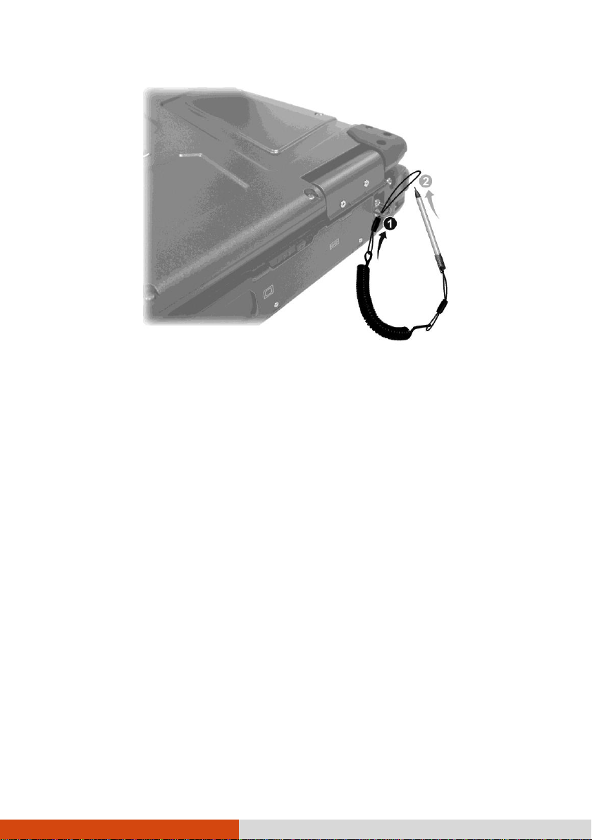
Using the Tether (Optional)
A tether is provided for attaching the stylus to your computer.
1. Insert one of the tether’s loop ends through the hole of the stylus (as indicated
by below). Then, insert the other end through the first loop (as indicated
by below) and pull it tight.
2. Insert the other loop end to the hook on the computer (as indicated by
below). Then, insert the stylus end through the loop (as indicated by below)
and pull it tight.
Getting Started 1-3
Page 14
Connecting to AC Power
The computer operates either on the external AC power or internal battery power.
It is suggested that you use AC power when you start up the computer for the
very first time.
CAUTION: Use only the AC adapter included with your computer. Using other AC
adapters may damage the computer.
1. Turn off the computer.
2. Plug the DC cord of the AC adapter to the power connector of the computer
().
1-4 Getting Started
Page 15
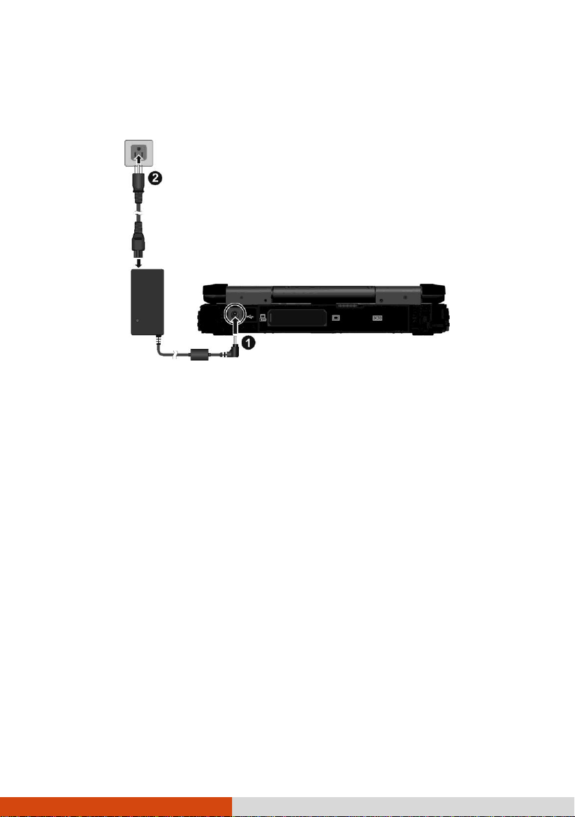
3. Plug the female end of the AC power cord to the AC adapter and the male
end to an electrical outlet ().
4. When the AC adapter is connected, power is being supplied from the electrical
outlet to the AC adapter and onto your computer. Now, you are ready to turn
on the computer.
CAUTION:
When you disconnect the AC adapter, disconnect from the electrical outlet first
and then from the computer. A reverse procedure may damage the AC
adapter or the computer.
When unplugging the connector, always hold the plug head. Never pull on the
cord.
NOTE: When the AC adapter is connected, it also charges the battery pack. For
information on using battery power, see Chapter 3.
Getting Started 1-5
Page 16
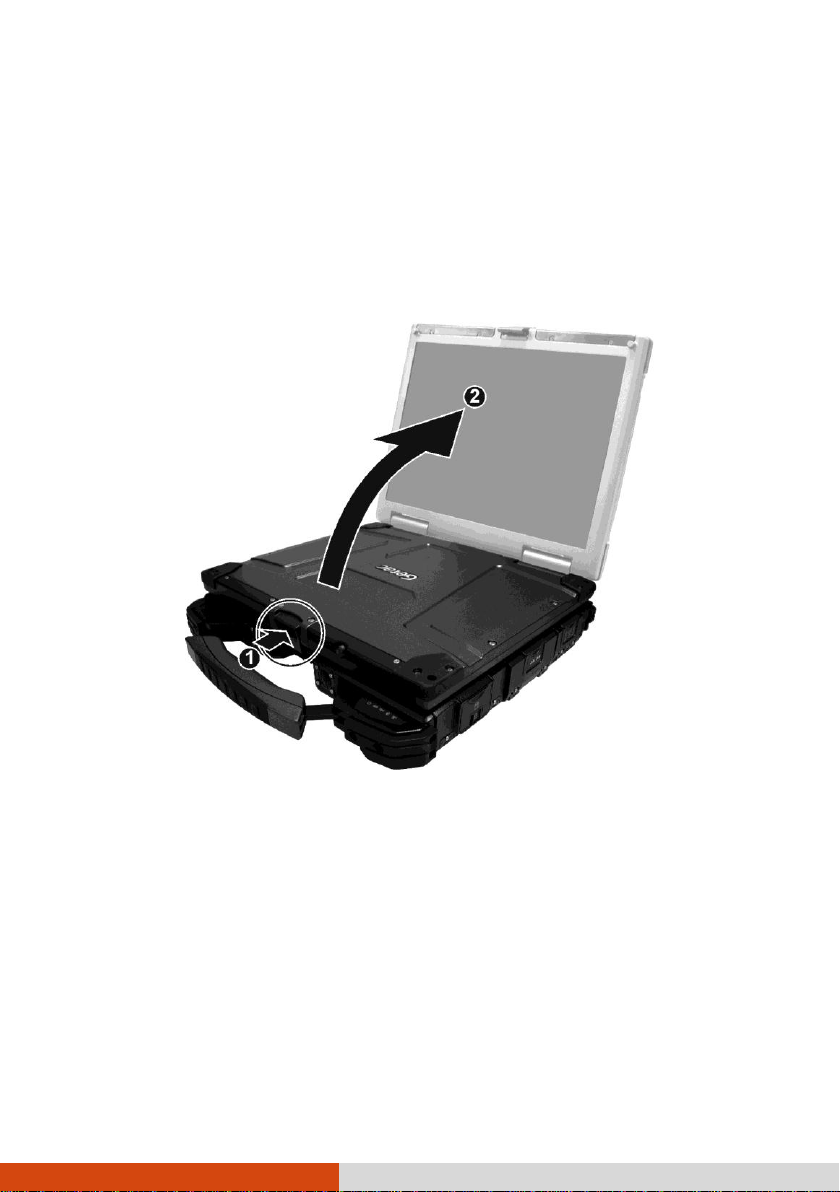
Turning On and Off the Computer
Turning On
1. Open the top cover by pushing on the cover latch () and lifting up the cover
(). You can tilt the cover forward or backward for optimal viewing clarity.
1-6 Getting Started
Page 17
To...
Do this...
Power off
(Shutdown)
Use the Windows Start menu in the lower left and follow the
shutdown procedure.
Sleep
Press the power button* or use the Windows Start menu to put
the computer in Sleep mode.
Hibernate
Use the Windows Start menu to put the computer in Hibernation
mode. (See “Hibernation” in Chapter 3 for more information.)
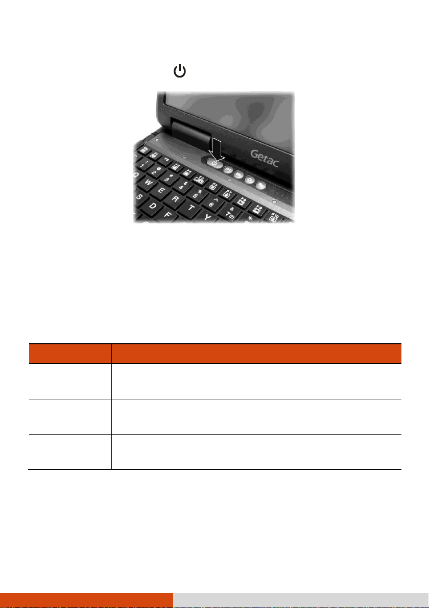
2. Press the power button (
3. Each time the computer is turned on, it performs a Power-On Self Test (POST),
and the operating system such as Windows should start.
).
Turning Off
When you finish a working session, you can stop the system by turning off the power
or leaving it in Sleep or Hibernation mode:
* “Sleep” is the default setting of the power button. You may change what the
power button does in Windows Control Panel.
Getting Started 1-7
Page 18
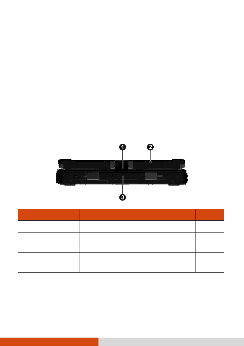
Ref
Component
Description
See Also
Top Cover Latch
Locks the top cover.
P. 1-5
WWAN Antenna
Should be pulled out for reception of mobile
telecommunications signals.
P. 2-24
Handle
Provides a convenient way to carry the
computer.
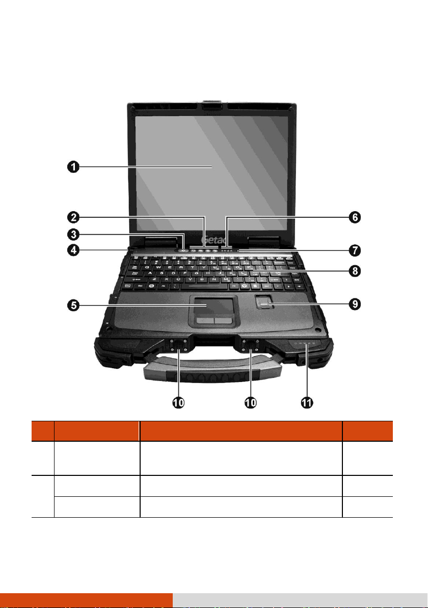
Taking a Look at the Computer
NOTE:
Depending on the model you purchased, the appearance of your computer
may not be exactly the same as those shown in this manual.
You need to open the protective covers to access the connectors. When not
using a connector, make sure to close the cover completely for water- and
dust-proof integrity. (Engage the locking mechanism if the cover is designed
with such mechanism.)
Front Components
1-8 Getting Started
Page 19
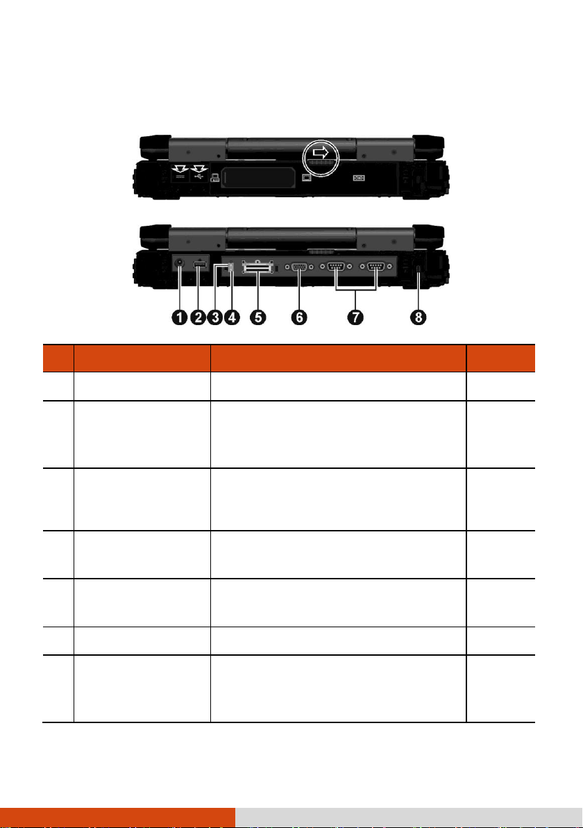
Ref
Component
Description
See Also
Power Connector
Connects the AC adapter.
P. 1-3
USB Port
Connects a USB device, such as a USB
flash disk, printer, digital camera, joystick,
and more.
P. 4-5
WWAN Passthrough Connector
(option)
Connects the external antenna for WWAN
(wireless wide area network) connectivity.
WiFi Pass-through
Connector (option)
Connects the external antenna for WLAN
(wireless local area network) connectivity.
Docking Connector
Connects to the office or vehicle dock
(purchased separately).
VGA Connector
Connects an external display monitor.
P. 4-2
Serial Connectors
Each of the two connectors connects a
serial mouse or serial communication
device.
P. 4-4
Rear Components
Getting Started 1-9
Page 20
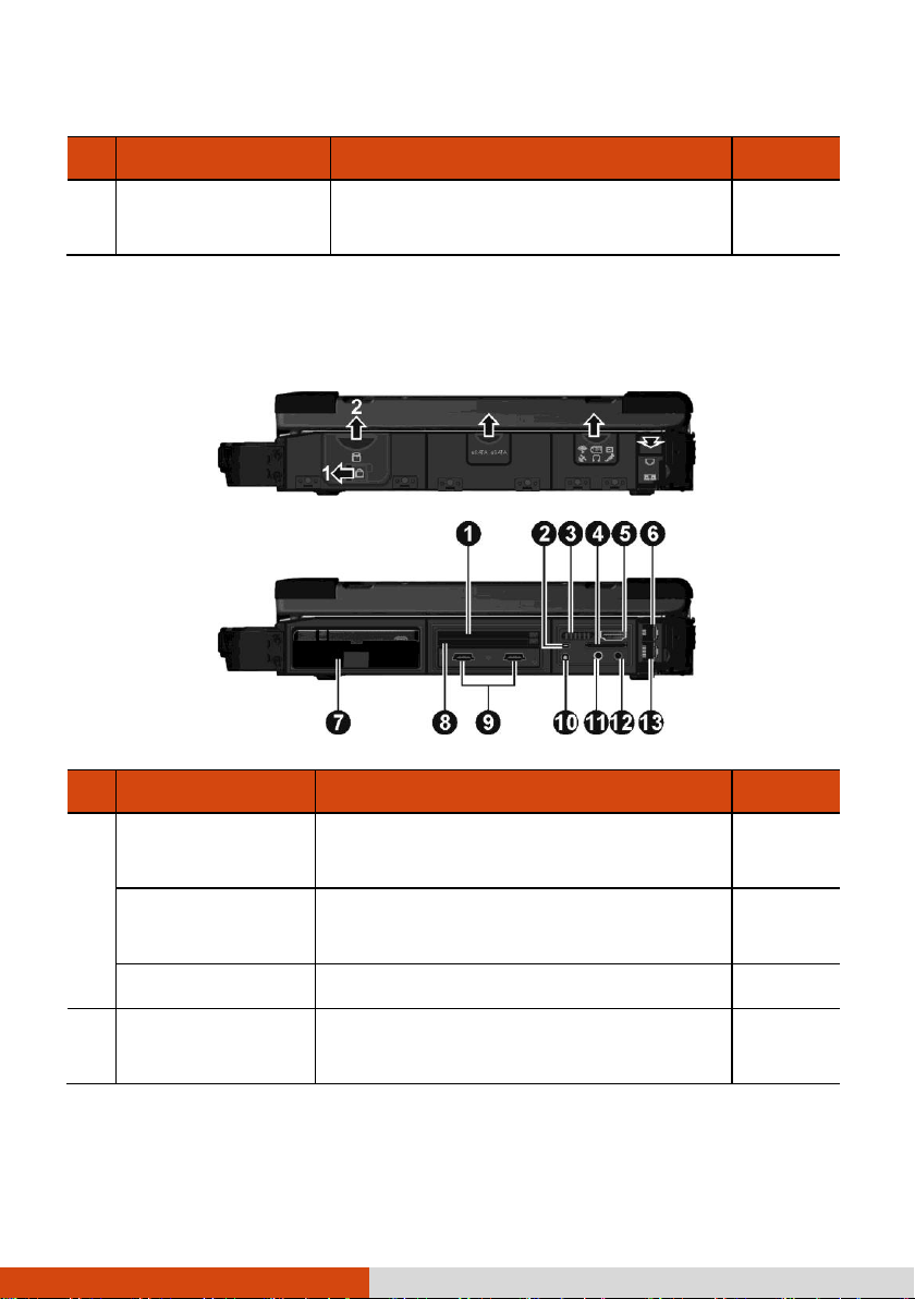
Ref
Component
Description
See Also
Kensington Lock
Locks the computer to a stationary object
for security.
P. 7-2
Ref
Component
Description
See Also
Expansion Card Slot
Depending on your model, the slot can be
any of the following:
ExpressCard Slot
Accepts an ExpressCard/34 or
ExpressCard/54 for additional functions.
P. 4-12
PCMCIA Slot
Accepts a PC card for additional functions.
P. 4-10
Mini IEEE 1394 Port
Connects an IEEE 1394 device such as a
scanner, printer, DVCAM, and VCR.
P. 4-6
Right-Side Components
1-10 Getting Started
Page 21

Ref
Component
Description
See Also
RF (radio
frequency) On/Off
Switch
Serves as the master on/off control for all
the wireless modules (wireless LAN,
Bluetooth, and WWAN).
NOTE: Available modules on your
computer depend on the configuration you
purchased.
P. 2-18,
2-21,
2-27
MMC/SD Card
Reader
Accepts a MultiMediaCard (MMC) or
Secure Digital (SD) card for removable
storage media.
P. 4-14
HDMI Connector
Connects a HDMI (High-Definition Multimedia Interface) monitor or TV set.
P. 4-2
RJ-11 Connector
Connects the telephone line.
P. 2-17
Hard Disk Drive
Compartment
Inside is the hard disk drive.
PCMCIA Slot
Accepts a PC card for additional functions.
P. 4-10
eSATA/USB Combo
Port
Connects an eSATA device such as an
external hard drive or optical drive.
P. 4-6
Can also function as a USB port.
GPS Pass-through
Connector (option)
Connects the external antenna for GPS
signal reception.
Audio Output
Connector
Connects a set of headphones or external
speakers with amplifier.
P. 4-8
Microphone
Connector
Connects an external microphone.
P. 4-8
RJ-45 Connector
Connects the LAN cable.
P. 2-18
Getting Started 1-11
Page 22
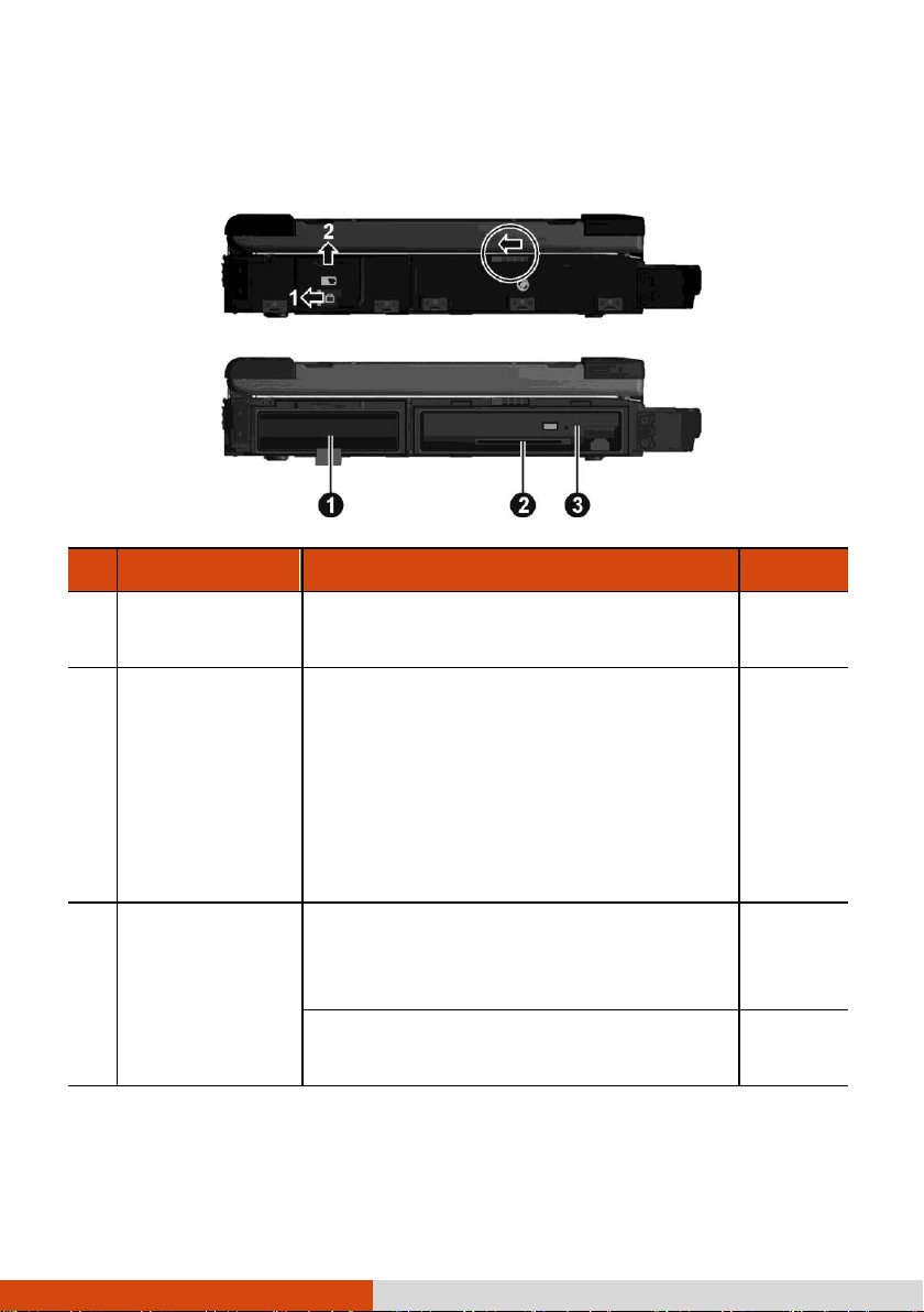
Ref
Component
Description
See Also
Battery Pack
Supplies power to your computer when
external power is not connected.
P. 3-3
Smart Card
Reader
Accepts a smart card for additional security
feature.
NOTE: On your computer, the Smart Card
reader is a part of the super multi drive
module. If the super multi drive module is
replaced by a secondary battery pack or
hard disk drive, you cannot use the Smart
Card reader.
P. 4-9
Super Multi Drive
Accepts a compact disc for installing or loading
software, accessing data, and playing
music/video.
P. 2-14
Can be replaced by a secondary hard disk
drive or battery pack (purchased separately).
P. 4-18
Left-Side Components
1-12 Getting Started
Page 23
Ref
Component
Description
See Also
LCD Screen
Displays the output of the computer. May
include the optional touchscreen feature.
P. 2-10
Quick Buttons
P1
Toggles the “Blackout” mode on or off.
P. 2-11
Top-open Components
Getting Started 1-13
Page 24
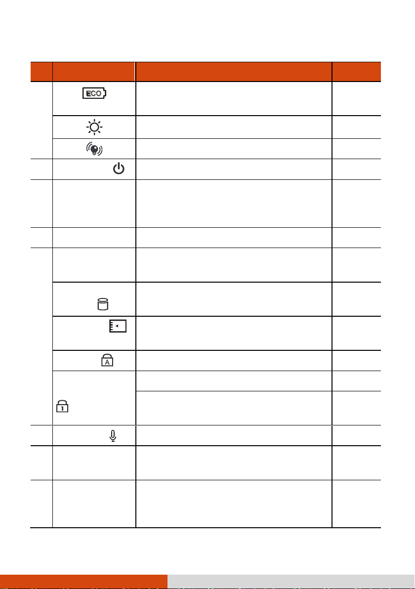
Ref
Component
Description
See Also
Toggles ECO power saving mode on or off
when using battery power.
P. 2-11
Toggles the sunlight-readable mode on or off.
P. 2-11
Enables or disables light sensor.
P. 2-11
Power Button
Turns the computer power on or off.
P. 1-7
Stylus (option)
Serves as the input device by tapping on the
screen to make selections and enter
information.
P. 2-10
Touchpad
Serves as the pointing device of the computer.
P. 2-7
Indicators
Show the current status of the computer’s
devices.
Hard Disk Drive /
DVD Drive
Blinks green when computer is accessing the
hard disk or DVD drive.
Card Reader
Blinks green when computer is accessing the
storage card.
P. 4-14
Caps Lock
Lights green when Caps Lock is on.
P. 2-3
Num Lock / HDD
Heater (option)
Lights green when Num Lock is on.
P. 2-18
Lights amber when the optional hard disk
heater is on.
Microphone
Receives sound and voice for the computer.
Keyboard
Serves as the data input device of the
computer.
P. 2-2
Fingerprint
Scanner
Serves as the fingerprint verification,
preventing unauthorized access to your
computer.
P. 2-28
1-14 Getting Started
Page 25
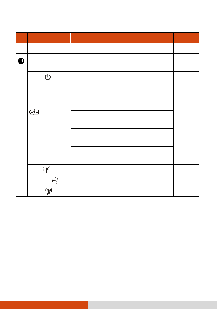
Ref
Component
Description
See Also
Stereo Speaker
Sends out sound and voice from the computer.
Indicators
Show the current status of the computer’s
devices.
Power
Lights green when computer is on.
P. 1-6
Blinks green when computer is on Sleep
mode.
Battery Charge
Lights green when the battery is fully charged.
P. 3-3
Lights amber when the battery is being
charged.
Blinks red when the battery’s capacity is below
10 %.
Blinks amber when the battery is in an
abnormal condition.
WLAN
Lights green when WLAN radio is on.
P. 2-18
Bluetooth
Lights green when Bluetooth radio is on.
P. 2-21
WWAN
Lights green when WWAN radio is on.
P. 2-27
Getting Started 1-15
Page 26
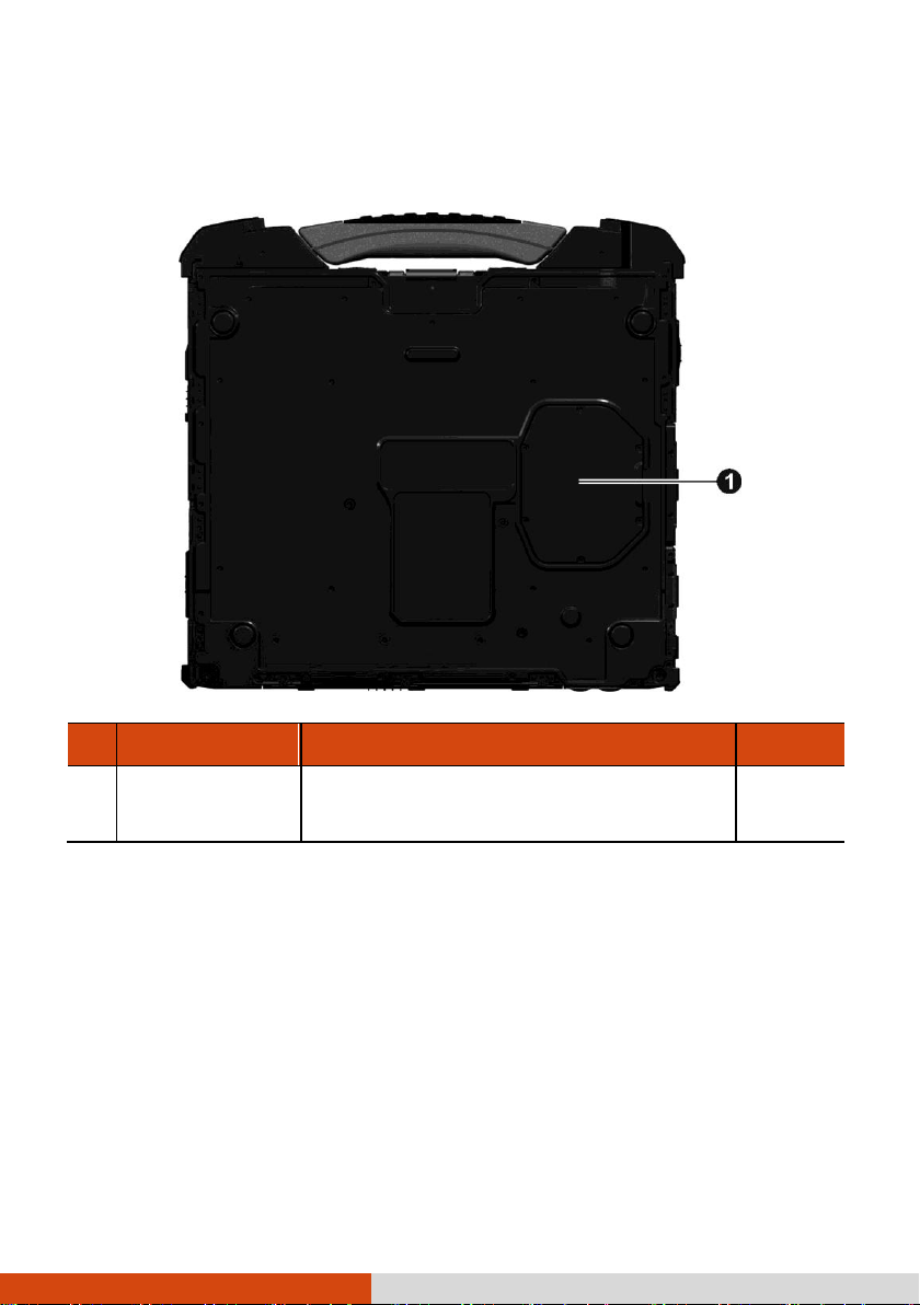
Ref
Component
Description
See Also
Memory Slots
Inside are the memory slots for expanding the
memory size of your computer.
P. 4-16
Bottom Components
1-16 Getting Started
Page 27

Chapter 2
Operating Your Computer
This chapter provides information about the use of the computer.
If you are new to computers, reading this chapter will help you learn the operating
basics. If you are already a computer user, you may choose to read only the parts
containing information unique to your computer.
CAUTION:
Do not expose your skin to the computer when operating it in a very hot or cold
environment.
The computer can get uncomfortably warm when you use it in high
temperatures. As a safety precaution in such a circumstance, do not place the
computer on your lap or touch it with your bare hands for extended periods of
time. Prolonged body contact can cause discomfort and potentially a burn.
Operating Your Computer 2-1
Page 28

Using the Keyboard
Your keyboard has all the standard functions of a full-sized computer keyboard plus
an Fn key added for specific functions.
The standard functions of the keyboard can be further divided into four major categories:
Typewriter keys
Cursor-control keys
Numeric keys
Function keys
Typewriter Keys
Typewriter keys are similar to the keys on a typewriter. Several keys are added
such as the Ctrl, Alt, Esc, and lock keys for special purposes. When the lock keys
(Caps Lock and Num Lk) are pressed, their corresponding indicators light up.
The Control (Ctrl) / Alternate (Alt) key is normally used in combination with other
keys for program-specific functions. The Escape (Esc) key is usually used for
stopping a process. Examples are exiting a program and canceling a command. The
function depends on the program you are using.
Cursor-Control Keys
Cursor-control keys are generally used for moving and editing purposes.
NOTE: The word “cursor” refers to the indicator on the screen that lets you know
exactly where on your screen anything you type will appear. It can take the form of
a vertical or horizontal line, a block, or one of many other shapes.
2-2 Operating Your Computer
Page 29
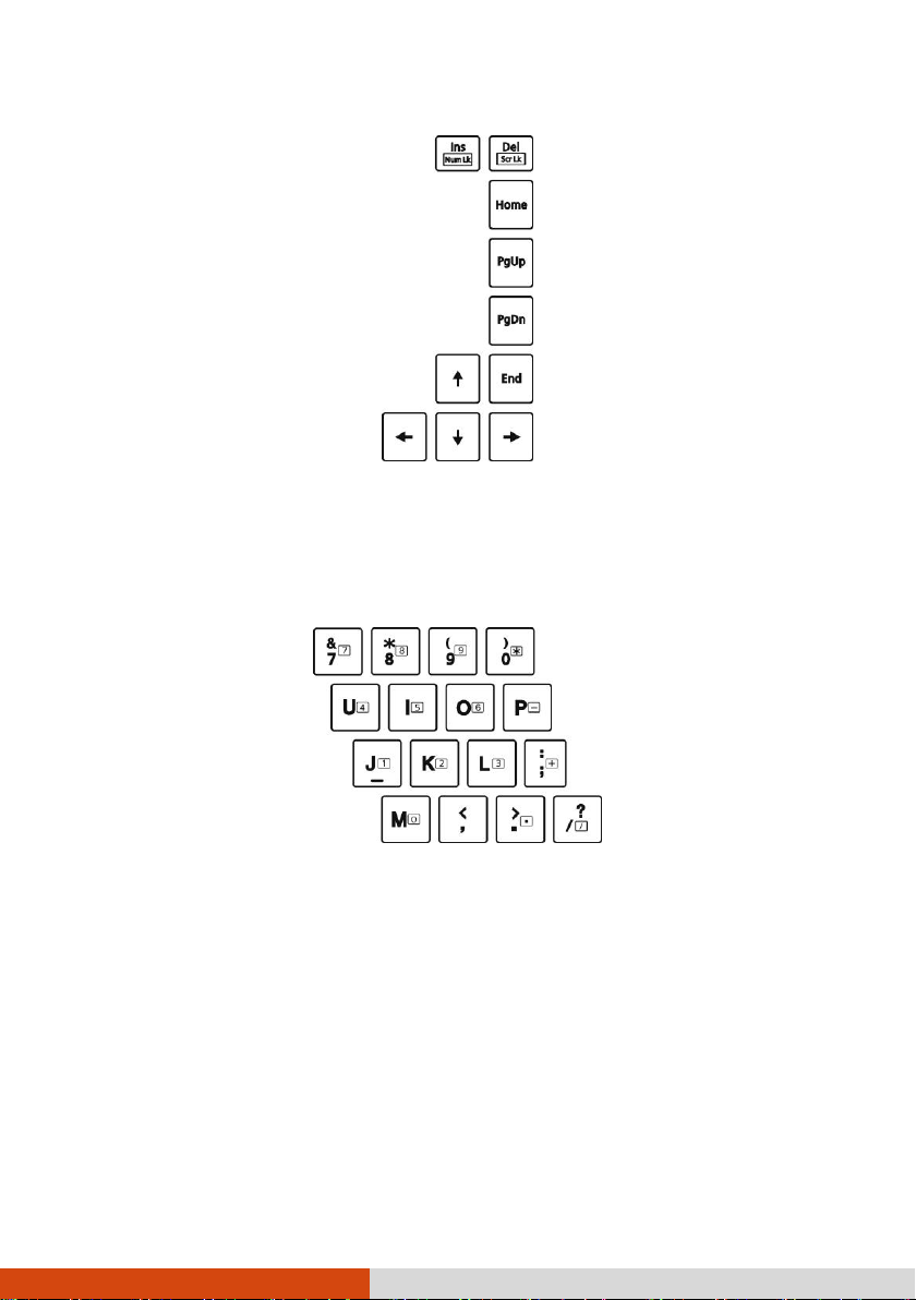
Numeric Keypad
A 15-key numeric keypad is embedded in the typewriter keys as shown next:
Numeric keys facilitate entering of numbers and calculations. When Num Lock is on,
the numeric keys are activated; meaning you can use these keys to enter numerals.
NOTE:
When the numeric keypad is activated and you need to type the English letter
in the keypad area, you can turn Num Lock off or you can press Fn and then
the letter without turning Num Lock off.
Some software may not be able to use the numeric keypad on the computer. If
so, use the numeric keypad on an external keyboard instead.
Operating Your Computer 2-3
Page 30

Key
Description
Switches the keyboard backlight on and off (option).
Switches the wireless LAN radio on and off.
Switches the night vision feature on and off for viewing the display
when using night vision goggles (optional).
Decreases the sound volume.
Function Keys
On the top row of the keys are the function keys: F1 to F12. Function keys are
multi-purpose keys that perform functions defined by individual programs.
Fn Key
The Fn key, at the lower left corner of the keyboard, is used with another key to
perform the alternative function of a key. The letter “Fn” and the alternative functions
are identified by the color of blue on the keytop. To perform a desired function,
first press and hold Fn, then press the other key.
Hot Keys
Hot keys refer to a combination of keys that can be pressed any time to activate
special functions of the computer. Most hot keys operate in a cyclic way. Each time
a hot key combination is pressed, it shifts the corresponding function to the other
or next choice.
You can easily identify the hot keys with the icons imprinted on the keytop. The
hot keys are described next.
2-4 Operating Your Computer
Page 31

Key
Description
Increases the sound volume.
Switches the display output to the next choice if an external display
(either VGA or HDMI) is connected.
The hot keys are equivalent to
Windows logo key + P.
Choices are:
LCD only
LCD + External display (Duplicate)
LCD + External display (Extend)
External display only
Decreases the LCD brightness.
The LCD still has 2 nits brightness when you reach the lowest
level.
Increases the LCD brightness.
Switches the touchscreen on and off (option).
Switches the touchpad off and on.
Switches the system sound output off (mute) and on.
Switches the display on and off.
Serves as the sleep button that you can define with Windows’
Power Options.
Operating Your Computer 2-5
Page 32

Windows Keys
The keyboard has two keys that perform Windows-specific functions: Windows
Logo key and Application key.
The Windows Logo key opens the Start menu and performs software-specific
functions when used in combination with other keys. The Application key usually
has the same effect as a right mouse click. (See your Windows manual for more
information.)
2-6 Operating Your Computer
Page 33

Using the Touchpad
CAUTION: Do not use a sharp object such as a pen on the touchpad. Doing so
may damage the touchpad surface.
NOTE:
Press Fn+F9 to toggle the touchpad on or off.
For optimal performance of the touchpad, keep your fingers and the pads
clean and dry. When tapping on the pad, tap lightly. Do not use excessive
force.
The touchpad is a pointing device that allows you to communicate with the computer
by controlling the location of the pointer on the screen and making selection with
the buttons.
The touchpad consists of a rectangular pad (work surface) and a left and right
buttons. To use the touchpad, place your forefinger or thumb on the pad. The
rectangular pad acts like a miniature duplicate of your display. As you slide your
fingertip across the pad, the pointer (also called cursor) on the screen moves
Operating Your Computer 2-7
Page 34

Term
Action
Point
Move your finger on the pad until the cursor points to the
selection on the screen.
Click
Press and release the left button.
–or–
Tap gently anywhere on the pad.
Double-click
Press and release the left button twice in quick succession.
–or–
Tap twice on the pad rapidly.
Drag and drop
Press and hold the left button, then move your finger until
you reach your destination (drag). Finally, release the button
(drop) when you finish dragging your selection to the
destination. The object will drop into the new location.
–or–
Gently tap twice on the pad and on the second tap, keep
your finger in contact with the pad. Then, move your finger
across the pad to drag the selected object to your destination.
When you lift your finger from the pad, the selected object
will drop into place.
accordingly. When your finger reaches the edge of the pad, simply relocate yourself
by lifting the finger and placing it on the other side of the pad.
Here are some common terms that you should know when using the touchpad:
2-8 Operating Your Computer
Page 35

Term
Action
Scroll
To scroll is to move up and down or left and right in the
working area on the screen.
To move vertically, place your finger on the right or left edge
of the pad and slide your finger up and down along the edge.
To move horizontally, place your finger on the top or bottom
edge of the pad and slide your finger left and right.
This function works only after you install the touchpad driver
supplied with the computer and it may not work for all
applications.
TABLE NOTE: If you swap the left and right buttons, “tapping” on the touchpad as
an alternative method of pressing the left button will no longer be valid.
Configuring the Touchpad
You may want to configure the touchpad to suit your needs. For example, if you
are a left-handed user, you can swap the two buttons so that you can use the
right button as the left button and vice versa. You can also change the size of
the on-screen pointer, the speed of the pointer, and so on.
To configure the touchpad, go to Control Panel Mouse Properties.
Operating Your Computer 2-9
Page 36

Using the Touchscreen (Optional)
NOTE: Press Fn+F8 to toggle the touchscreen on or off.
CAUTION: Do not use a sharp object such as a ballpoint pen or pencil on the
touchscreen. Doing so may damage the touchscreen surface. Use your finger or
the included stylus.
The touchscreen is a touch-sensitive device that allows you to navigate on the screen
without using a keyboard, touchpad, or mouse.
Use the included stylus to select objects on the screen. The stylus can be stretched
for better grip and handling.
2-10 Operating Your Computer
Page 37

Term/Action
Equivalent Mouse
Function
Tap: Touch the screen once.
Click/Point
Double-tap: Touch the screen twice rapidly.
Double-click
Tap and hold: Tap and hold until a popup menu appears.
Right-click
Drag: Hold the stylus (or finger) on the screen and drag
across the screen until reaching your destination.
Drag
The following table shows how you use the touchscreen to obtain equivalent mouse
functions.
Operating Your Computer 2-11
Page 38

Button
Description
P1
Toggles the “Blackout” mode on or off.
In Blackout mode, the LCD backlight and LED indicators are turned off.
To bring the computer out of Blackout mode, press P1 or the power
button.
NOTE: “Blackout” is the default setting of the P1 button. You can
re-define the button. (See “P1 Quick Button Definition Utility” in
Chapter 6 for information.)
Toggles ECO power saving mode on or off when using battery power.
In ECO mode, the system turns down the panel backlight and sacrifices
processing speed to gain more battery life. The button lights green while
in ECO mode.
NOTE: The button works only when using battery power.
Toggles the sunlight-readable mode on or off.
In sunlight-readable mode, the LCD brightness is increased to the highest
level. The button lights green while in sunlight-readable mode.
Using the Quick Buttons
Located on top of the keyboard are four quick buttons:
2-12 Operating Your Computer
Page 39

Button
Description
Enables or disables light sensor.
When enabled, your computer automatically adjusts the LCD brightness
based on the surrounding lighting condition. The button lights green while
light sensor is enabled.
Operating Your Computer 2-13
Page 40

Using the DVD Drive
Your computer may come with a Super Multi drive. The drive can read from and
write to CD, DVD+, DVD- and DVD-RAM media.
CAUTION:
When inserting a disc, do not use force.
Make sure that the disc is correctly inserted into the tray, and then close the
tray.
Do not leave the drive tray open. Also, avoid touching the lens in the tray with
your hand. If the lens becomes dirty, the drive may malfunction.
Do not wipe the lens using materials with rough surface (such as paper towel).
Instead, use a cotton swab to gently wipe the lens.
FDA regulations require the following statement for all laser-based devices:
“Caution, Use of controls or adjustments or performance of procedures other than
those specified herein may result in hazardous radiation exposure.”
NOTE: The DVD drive is classified as a Class 1 laser product. This label is located
on the DVD drive.
NOTE: For DVD and Combo drives only.
This product incorporates copyright protection technology that is protected by
method claims of certain U.S. patents and other intellectual property rights owned
by Macrovision Corporation and other rights owners. Use of this copyright
protection technology must be authorized by Macrovision Corporation, and is
intended for home and other limited viewing uses only unless otherwise authorized
by Macrovision Corporation. Reverse engineering or disassembly is prohibited.
Inserting and Removing a Disc
Follow this procedure to insert or remove a disc:
2-14 Operating Your Computer
Page 41

Eject button
1. Turn on the computer.
2. Open the multi-purpose bay cover by sliding the release latch towards the left.
3. Press the eject button and the DVD tray will slide out partially. Gently pull on
it until it is fully extended.
4. To insert a disc, place down the disc in the tray with its label facing up. Slightly
press the center of the disc until it clicks into place.
To remove a disc, hold the disc by its outer edge and lift it up from the tray.
5. Gently push the tray back into the drive.
6. Close the multi-purpose bay cover.
NOTE: In the unlikely event that you are unable to release the drive tray by
pressing the eject button, you can manually release the disc. (See “Optical Drive
Problems” in Chapter 8.)
Operating Your Computer 2-15
Page 42

2-16 Operating Your Computer
Page 43

Using the Network Features
Using the Modem
The internal 56 K fax/data modem allows you to use the telephone line to communicate
with others by fax, email, or connect to an online service or bulletin board.
To connect the telephone line to the modem, connect one end of the modem cable
to the RJ-11 connector on the computer and the other end to the phone line.
NOTE:
When using the communication software, you may have to disable power
management.
Set the COM port of the modem to COM3.
Set parameters such as modem speed (baud rate) and line type (pulse dialing
or tone dialing).
Do not enter the Sleep mode when using the communication software.
Operating Your Computer 2-17
Page 44

Using the LAN
The internal 10/100/1000Base-T LAN (Local Area Network) module allows you
to connect your computer to a network. It supports data transfer rate up to 1000
Mbps.
To connect the network cable to the LAN module, connect one end of the LAN
cable to the RJ-45 connector on the computer and the other end to the network
hub.
Using the Wireless LAN
The WLAN module supports IEEE 802.11a/b/g/n.
Turning On/Off the WLAN Radio
NOTE: The FAA (Federal Aviation Agency) has deemed it unsafe to operate
wireless devices in aircraft as this may interfere with flight safety. Remember to
turn off wireless LAN when using your computer in the airplane.
To turn on the WLAN radio:
1. Make sure that the RF switch is at the ON position.
2-18 Operating Your Computer
Page 45

2. Press Fn+F1 to turn on the WLAN radio, indicated by the WLAN indicator (
glowing in green when on.
3. Windows Mobility Center has wireless network turned on by default. The Wireless
Network icon on the taskbar should appear without a red X. (In case you
have previously turned it off in Windows Mobility Center, be sure to turn it on
when using the function the next time.)
To turn off the WLAN radio, press Fn+F1. To quickly turn off all radio, slide the
RF switch to the OFF position.
)
Connecting to a Wireless Network
1. Make sure that the WLAN function is enabled (as described above).
2. Tap the Wireless Network icon on the taskbar. (An orange light in the icon
indicates connections are available.)
3. In the list of available wireless networks, tap a network, and then tap Connect.
Operating Your Computer 2-19
Page 46

4. Some networks require a network security key or passphrase. To connect to one
of those networks, ask your network administrator or Internet service provider
(ISP) for the security key or passphrase.
NOTE:
Once you have connected to a wireless network, a profile is added in
Windows. By default, Windows will automatically connect to the wireless
network when it is in range.
For more information on connecting to a wireless network, see Windows’
online help.
2-20 Operating Your Computer
Page 47

Using the Bluetooth Feature
The Bluetooth technology allows short-range (about 10 meters for Class 2 devices)
wireless communications between devices without requiring a cable connection. Data
can be transmitted through walls, pockets and briefcases as long as two devices
are within range.
Turning On/Off the Bluetooth Radio
1. Make sure that the RF switch is at the ON position.
2. Right-click the Getac Utility icon ( ) located on Windows taskbar and select
Quick Bar. (You need to tap on the taskbar to show the hidden icons.)
3. The Quick Bar appears. To turn on the Bluetooth feature, click the Bluetooth
quick button. The Bluetooth indicator ( ) will glow in green.
Operating Your Computer 2-21
Page 48

4. The Bluetooth function is enabled by default, as indicated by the Bluetooth icon
on the Windows taskbar. (In case you have previously disabled the function
in the Bluetooth utility, be sure to enable it when using the function the next
time.)
To turn off the Bluetooth radio, use the Quick Bar or Bluetooth utility. To quickly
turn off all radio, slide the RF switch to the OFF position.
Connecting to another Bluetooth Device
1. Make sure that the Bluetooth function is enabled (as described above).
2. Make sure that the target Bluetooth device is turned on, discoverable and within
close range. (See the documentation that came with the Bluetooth device.)
3. To search for Bluetooth devices, right click the Bluetooth icon
a Device.
4. Select the device you want to connect from the search results.
2-22 Operating Your Computer
and select Add
Page 49

5. Depending on the type of Bluetooth device that you want to connect to, you
will need to enter the pertinent information.
For detailed information on using the Bluetooth feature, see Windows’ online Help.
Operating Your Computer 2-23
Page 50

Using the WWAN Feature (Optional)
A WWAN (Wireless Wide Area Network) uses mobile telecommunication cellular
network technologies to transfer data. The WWAN module of your computer supports
3G or 4G LTE depending on your model.
NOTE:
Your model only supports data transmission, voice transmission is not
supported.
When using the WWAN feature, pull out the WWAN antenna.
2-24 Operating Your Computer
Page 51

Installing a SIM Card
To use the WWAN feature to connect to the Internet, you need to subscribe to WWAN
service and acquire a SIM card from the service provider. To install the SIM card,
follow these steps:
1. Turn off the computer and disconnect the AC adapter.
2. Open the media bay cover by sliding the release latch towards the left.
3. Press upward the release latch () and pull the ribbon strip () to slide
the existing device out of the media bay.
4. Carefully place your computer upside down.
Operating Your Computer 2-25
Page 52

5. Locate the SIM card slot. Insert the SIM card into the slot. Make sure the beveled
corner on the SIM card is facing towards the slot and that the golden contact
area on the card is facing downwards.
6. Replace the media bay device.
7. Close the media bay cover.
NOTE: To remove the SIM card, push inward to release and slide the SIM card out
of the slot.
2-26 Operating Your Computer
Page 53

Turning On/Off the WWAN Radio
1. Make sure that the RF switch is at the ON position.
2. Right-click the Getac Utility icon ( ) located on Windows taskbar and select
Quick Bar. (You need to tap on the taskbar to show the hidden icons.)
3. The Quick Bar appears. To turn on the WWAN feature, click the WWAN quick
button. The WWAN indicator ( ) will glow in green.
To turn off the WWAN radio, use the Quick Bar. To quickly turn off all radio, slide
the RF switch to the OFF position.
You can use the WWAN software application to configure and use WWAN connections.
See the online help for information.
Operating Your Computer 2-27
Page 54

Using the Fingerprint Scanner
WARNING:
To protect the fingerprint scanner, be sure to slide close the cover when not
using the fingerprint scanner.
We shall not be liable for any loss or damage whatsoever resulting from your
use of the fingerprint scanner or neglect of fingerprint scanner use, or any data
loss resulting from such developments as fingerprint authentication
malfunctioning.
It is not recommended that you use the fingerprint scanner in a below-freezing
temperature. The moisture on your finger can freeze to the scanner’s metal
surface when you touch it, resulting in a failed operation.
The fingerprint scanner provides a strong authentication mechanism based on fingerprint
recognition. It features:
Website Log On
Logon to your web accounts like banks, webmail, and more with a simple swipe
of your finger.
Windows Log On
Logon to Microsoft® Windows® with a simple swipe of your finger every time
you turn on your computer or log onto your desktop.
QuickLaunch
Quickly launch all your favorite websites, open files and folders, and log in to
your accounts with a simple swipe of your finger.
KeepSafe
Protect your pictures, personal files, and folders using your fingerprint so only
you can access them.
2-28 Operating Your Computer
Page 55

To register your fingerprint and configure the function:
NOTE: You can register a fingerprint only after creating a password for the
Windows user account.
1. Locate and slide open the fingerprint scanner cover.
2. To register your fingerprint, click Start All Programs AuthenTec TrueSuite
AuthenTec TrueSuite. Click the finger you want to register and follow the onscreen
instructions to complete.
Operating Your Computer 2-29
Page 56

3. You can then use the Fingerprint Software to set up how the fingerprint
authentication works.
2-30 Operating Your Computer
Page 57

App Store
Settings
Options
Help
For detailed information, click the Help button of the software.
Operating Your Computer 2-31
Page 58

Page 59

Chapter 3
Managing Power
Your computer operates either on external AC power or on internal battery power.
This chapter tells you how you can effectively manage power. To maintain optimal
battery performance, it is important that you use the battery in the proper way.
Managing Power 3-1
Page 60

AC Adapter
CAUTION:
The AC adapter is designed for use with your computer only. Connecting the
AC adapter to another device can damage the adapter.
The AC power cord supplied with your computer is for use in the country where
you purchased your computer. If you plan to go overseas with the computer,
consult your dealer for the appropriate power cord.
When you disconnect the AC adapter, disconnect from the electrical outlet first
and then from the computer. A reverse procedure may damage the AC
adapter or computer.
When unplugging the connector, always hold the plug head. Never pull on the
cord.
The AC adapter serves as a converter from AC (Alternating Current) to DC (Direct
Current) power because your computer runs on DC power, but an electrical outlet
usually provides AC power. It also charges the battery pack when connected to AC
power.
The adapter operates on any voltage in the range of 100~240 V AC.
3-2 Managing Power
Page 61

Battery Pack
The battery pack is the internal power source for the computer. It is rechargeable
using the AC adapter.
The operating time of a fully charged battery pack depends on how you are using
the computer. When your applications often access peripherals, you will experience
a shorter operating time.
NOTE: Care and maintenance information for the battery is provided in the
“Battery Pack Guidelines” section in Chapter 7.
Charging the Battery Pack
NOTE:
Charging will not start if the battery’s temperature is below 0 C (32 F) or
above 40 C (104 F).
The charging process will stop when the battery’s temperature gets above 60
C (140 F). The Battery Charge Indicator turns off in this state. Once the
battery’s temperature drops within the safe range, charging will automatically
resume with the Battery Charge Indicator glowing amber.
During charging, do not disconnect the AC adapter before the battery has
been fully charged; otherwise you will get a prematurely charged battery.
To charge the battery pack, connect the AC adapter to the computer and an electrical
outlet. The Battery Charge Indicator ( ) on the computer glows amber to
indicate that charging is in progress. You are advised to keep the computer power
off while the battery is being charged. When the battery is fully charged, the Battery
Charge Indicator lights green.
Managing Power 3-3
Page 62

Battery Type
Charging Time
Computer is Off
Computer is On and
in Idle State
9-cell (4 A)
3.5~4.5 hours
4.0~6.0 hours
The charging times are as follows:
CAUTION: After the computer has been fully recharged, do not immediately
disconnect and reconnect the AC adapter to charge it again. Doing so may
damage the battery.
NOTE: The battery level may automatically lessen due to the self-discharge
process (0.21 % per day), even when the battery pack is fully charged (100 %).
This happens no matter if the battery pack is installed in the computer.
Initializing the Battery Pack
You need to initialize a new battery pack before using it for the first time or when
the actual operating time of a battery pack is much less than expected.
Initializing is the process of fully charging, discharging, and then charging. It can
take several hours.
1. Make sure that the computer power is turned off. Connect the AC adapter to
fully charge the battery pack.
2. After the battery pack is fully charged, turn on the computer. When the message
“Press F2 to Enter BIOS Setup” appears, press F2 to enter the program.
3. Disconnect the AC adapter and leave the computer on until the battery is fully
discharged. The computer will shut down automatically.
4. Connect the AC adapter to fully charge the battery pack.
3-4 Managing Power
Page 63

Switch
Checking the Battery Level
NOTE: Any battery level indication is an estimated result. The actual operating
time can be different from the estimated time, depending on how you are using the
computer.
By Operating System
You can check the approximate battery level using the battery meter function of the
operating system. To read the battery level in Windows, click the battery icon on
the taskbar.
By Gas Gauge
On the exterior side of the battery pack is a gas gauge for displaying the estimated
battery charge. When the battery pack is not installed in the computer and you want
to know the battery charge, you can press the switch with a pointed device to see
the corresponding value of indicator segment that light green.
The value of the corresponding green segment indicates the relative percentage of
the battery charge. The battery pack is fully discharged when you see no segment
glowing green.
Managing Power 3-5
Page 64

Replacing the Battery Pack
CAUTION:
There is danger of explosion if the battery is incorrectly replaced. Replace the
battery only with the computer manufacturer’s optional battery packs. Discard
used batteries according to the dealer’s instructions.
Do not attempt to disassemble the battery pack.
If you often rely on battery power for a long period of time while traveling, you
may consider the purchase of an additional battery pack from your dealer and keep
it with you in a fully charged state as a backup.
To replace the battery pack, follow these steps:
1. Turn off the computer and disconnect the AC adapter.
2. Locate the battery compartment on the left side of the computer.
3. Slide the cover lock to the left () and then lift the release latch () to
open the compartment cover.
4. Pull the ribbon strip and slide the battery pack out of the compartment.
5. With the ribbon strip facing outward, insert the new battery pack all the way
into the compartment.
3-6 Managing Power
Page 65

6. Close the cover, press the release latch downward to engage, and then slide
the lock towards the right to secure the cover.
Managing Power 3-7
Page 66

Battery
Icon
Battery Level
Description
Discharging
The icon shows the charge remaining in 10-percent
increments until the charge reaches the low-battery
level.
Low
The battery charge has reached the low-battery level
(10% by default).
Critically low
The battery charge has reached the critical battery
level (5% by default). By default, Windows will
display a notification and put your computer into
Hibernation.
Battery Low Signals and Actions
The battery icon changes appearance to display the current state of the battery.
When the battery is low, the computer’s Battery Charge Indicator (
red to alert you to take actions.
) also blinks
Always respond to low-battery by connecting the AC adapter, placing your computer
in Hibernation mode, or turning off the computer.
3-8 Managing Power
Page 67

What...
When...
Power to the hard disk is turned off
When the hard disk has been idle for a set
period.
Power to the display is turned off
When the display has been idle for a set
period.
The computer enters the Sleep mode.
The hard disk and display are turned
off and the entire system consumes less
power.
When the entire system has been idle for
a set period.
When you manually activate the mode.
The computer enters the Hibernation
mode. (See the next subsection for
more information.)
When the entire system has been idle for
a set period.
When you manually activate the mode.
Power Management
Your computer supports ACPI (Advanced Configuration and Power Interface) for
power management. The power management feature allows you to reduce the power
consumption for energy saving.
With an ACPI-compliant operating system such as Windows, power supply to different
computer components is controlled on an as-needed basis. This allows maximum
power conservation and performance at the same time.
In general, Windows’ power management works in this way:
For detailed information on power management, see Windows’ Help.
Managing Power 3-9
Page 68

Hibernation
Hibernation is a very useful feature. People frequently open many applications when
they use computers. It takes some time to get all these applications open and running,
and normally they all have to be closed before the computer can be turned off.
When you use the hibernation feature, you do not have to close the applications.
The computer stores the state of your computer to a file on the hard disk and then
shuts down. The next time you turn on your computer, you return to exactly where
you left off.
3-10 Managing Power
Page 69

Power-Saving Tips
Aside from enabling your computer’s power saving mode (see previous section),
you can do your part to maximize the battery’s operating time by following these
suggestions.
Enter power saving mode when using battery power.
Do not disable automatic power management features.
Decrease the LCD brightness to the lowest comfortable level.
Shorten the length of time before Windows turn off the display.
Many USB devices use power just by being connected. If you use a USB mouse,
you can save power by disconnecting the mouse and using the touchpad. If
you use a USB flash drive, unplug it when you are not using it.
Remove the card (such as PC card, ExpressCard, and Smart Card) if not using
it.
Turn off the wireless radio if you are not using the wireless module (such as
WLAN, Bluetooth, or 3G).
Turn off the computer when you are not using it.
Managing Power 3-11
Page 70

Page 71

Chapter 4
Expanding Your
Computer
You can expand the capabilities of your computer by connecting other peripheral
devices. When using a device, be sure to read the instructions accompanying the
device together with the relevant section in this chapter.
Expanding Your Computer 4-1
Page 72

VGA
HDMI
Connecting a VGA or HDMI Display
Monitor
If you want the benefits of a larger display screen with higher resolution, you can
connect an external display monitor to your computer
Your computer supports a VGA connector and a HDMI connector. HDMI
(High-Definition Multimedia Interface) is an audio/video interface that transmits
uncompressed digital data and therefore delivers true HD quality. As a home theater
system most likely includes a widescreen HDTV and surround-sound system, you
can use the home theater system to view/play media stored on your computer by
connecting via the HDMI interface.
Follow this procedure to connect an external monitor:
1. Turn off the computer.
2. Depending on the type of your monitor, plug the monitor’s signal connector to
the computer’s VGA or HDMI connector.
4-2 Expanding Your Computer
Page 73

3. Plug one end of the monitor’s power cord into the power socket on the monitor
and the other end to an electrical outlet.
4. To use the monitor, turn on the monitor before turning on the computer.
5. The connected device should respond by default. If not, you can switch the display
output by pressing the Fn+F5 hot keys. (You can also change the display through
Windows Control Panel Display Settings Properties.)
CAUTION: Do not disconnect the external monitor while the computer is in the
Sleep mode or Hibernation mode. If no external monitor is connected when the
computer resumes, the LCD might not display properly.
Expanding Your Computer 4-3
Page 74

Connecting a Serial Device
Your computer has two serial ports for connecting a serial device such as a serial
mouse or serial communication device (modem).
Follow this procedure to connect a serial device:
1. Turn off the computer.
2. Plug the device cable to the serial port on the rear of the computer.
3. Turn on the computer.
NOTE: Portable modems that derive power through the serial port cannot be used
with the computer. Instead, use a modem that is powered by its own internal
battery or external AC power.
4-4 Expanding Your Computer
Page 75

Connecting a USB Device
Your computer has one USB 3.0 port and two eSATA/USB 3.0 ports for connecting
USB devices, such as a digital camera, scanner, printer, modem, and mouse.
The USB ports support transfer rate up to 5.0 Gbit/s for USB 3.0 devices.
To connect a USB device, plug the device cable to one of the USB ports.
Expanding Your Computer 4-5
Page 76

Connecting an eSATA Device
Your computer has two eSATA/USB combo ports for connecting eSATA devices (such
as an external hard drive and external optical drive) / USB devices (see previous
section).
The port supports SATA II with transfer rate up o 3.0Gbit/s. It can provide 5V
power if a certified USB-eSATAcombo cable is used.
To connect an external eSATA device, plug the device cable to one of the eSATA
ports.
4-6 Expanding Your Computer
Page 77

Connecting an IEEE 1394 Device
Your computer has a mini IEEE 1394 port for connecting IEEE 1394 devices that
include not only computer peripheral devices such as scanner, printer and high-quality
CCD, but also consumer electronic equipment such as DVCAM and VCR.
To connect an IEEE 1394 device, prepare an IEEE 1394 cable. Plug the appropriate
end of the cable to the computer’s mini IEEE 1394 connector and the other end
to the device’s corresponding connector.
Expanding Your Computer 4-7
Page 78

Connecting Audio Devices
For higher audio quality, you can send or receive sound through external audio devices.
NOTE: After connecting an external audio device, make sure that you specify the
use of the correct audio device in Windows.
Audio Output Connector (green) can be connected to speakers, headphones, or
earphone set.
Microphone Connector (pink) can be connected to an external microphone for
recording voice or sound.
NOTE: When using the external speakers/headphones or microphone, you
cannot use the internal one.
4-8 Expanding Your Computer
Page 79

Chip
Using Smart Cards
NOTE: On your computer, the Smart Card reader is a part of the super multi drive
module. If the super multi drive module is replaced by a secondary battery pack or
hard disk drive, you cannot use the Smart Card reader.
With an embedded microcontroller, smart cards have the unique ability to store large
amounts of data, carry out their own on-card functions (e.g., encryption and mutual
authentication), and interact intelligently with a smart card reader.
To insert a smart card:
1. Locate the smart card slot on the left of the computer and open the cover.
2. Slide the smart card, with its label and embedded computer chip facing up into
the slot.
3. When a new card is seated, use the third-party smart card software to allow
your computer to read it.
To remove a smart card:
1. Make sure that the third-party smart card software is not accessing the smart
card.
2. Pull the card out of the slot.
Expanding Your Computer 4-9
Page 80

Eject button
Using PC Cards
Depending on your model, your computer has one or two PC card slots which support
type II card and CardBus specifications.
NOTE:
Some PC cards require additional system resources. Before using such PC
card, you may have to free other system resources for the PC card.
Although some PC cards can be inserted and removed without turning off the
computer, you cannot remove or install PC cards during Sleep mode.
To insert a PC card:
1. Locate the PC card slot(s) on the right side of the computer and open the
cover.
2. Slide the PC card, with its label facing up, into the slot until the eject button
pops out.
3. When a new card is seated, the computer will detect it and try to install the
appropriate driver. Follow the on-screen instructions to complete the process.
4-10 Expanding Your Computer
Page 81

To remove a PC card:
1. Double-click on the Safely Remove Hardware icon found on the Windows
taskbar and the Safely Remove Hardware window appears on screen.
2. Select (highlight) the PC card from the list to disable the card.
3. Push the eject button and the card will slide out slightly.
4. Pull the card out of the slot.
Expanding Your Computer 4-11
Page 82

Using ExpressCards (Optional)
Depending on the model, your computer has an ExpressCard slot.
ExpressCard supports the PCI Express and USB 2.0 serial data interfaces (supporting
speeds of up to 2.5 Gbps and 480 Mbps respectively), improving speed in data
transfer while conserving power usage.
The ExpressCard slot can accommodate a 54 mm (ExpressCard/54) or 34 mm
(ExpressCard/34) wide ExpressCard. Typical ExpressCards support a very extensive
range of applications including memory, wired and wireless communication cards, and
security devices.
Shown next are the appearances of ExpressCards for your reference.
ExpressCard/54 ExpressCard/34
To insert an ExpressCard:
1. Locate the ExpressCard slot on the right side of the computer and open the
cover.
2. Slide the ExpressCard, with its label facing up, all the way into the slot until
the rear connectors click into place.
4-12 Expanding Your Computer
Page 83

3. When a new card is seated, the computer will detect it and try to install the
appropriate driver. Follow the on-screen instructions to complete the process.
To remove an ExpressCard:
1. Double-click on the Safely Remove Hardware icon found on the Windows
taskbar and the Safely Remove Hardware window appears on screen.
2. Select (highlight) the ExpressCard from the list to disable the card.
3. Push the eject button and the card will slide out slightly.
4. Pull the card out of the slot.
Expanding Your Computer 4-13
Page 84

Type
MMC Card
SD Card
Appearance
Size
24×32×1.4
(mm)
24×32×2.1
(mm)
Using the MMC/SD Card Reader
NOTE:
If your hard disk is divided into several drives, make sure that all drives have
been formatted before using the Card Reader. Otherwise, you may encounter
problems when using the Card Reader.
You can use only storage cards. Your Card Reader does not support cards
with I/O (input/output) functions such as a wireless network card or Bluetooth
card.
Your computer has a Card Reader. The Card Reader is a small drive for reading
from and writing to removable storage cards (or called memory cards). The Card
Reader supports the MultiMediaCard (MMC) and Secure Digital (SD) cards.
Shown next are the appearance and size of each card type for your reference.
4-14 Expanding Your Computer
Page 85

To insert a storage card:
1. Locate the Card Reader slot on the right side of the computer and open the
cover.
2. Align the card with its connector pointing to the slot and its label facing down.
Slide the card into the slot until it reaches the end.
3. Windows will detect the card and assign it a drive name.
To remove a storage card:
1. Double-click My Computer.
2. Right-click the drive with the card and select Eject.
3. Pull the card out of the slot.
Expanding Your Computer 4-15
Page 86

System Memory Upgrade
You can upgrade your computer by changing system memory to a maximum of 8
GB on the two DDR3 1333/1600 MHz SO-DIMM slots.
CAUTION: RAM modules are extremely sensitive to static electricity. There are
cases where static electricity generated by the human body has adversely affected
such modules. When inserting or removing a RAM module, do not touch the
terminals or internal components, insert objects other than the module, or allow
foreign particles to enter. Doing so has been known to cause damage, fire, or
electrical shock.
To install the RAM module:
1. Remove the battery pack (see chapter 3) and make sure that the computer
is not connected to AC power.
2. Carefully place the computer upside down.
4. Remove the six screws to open the compartment cover.
4-16 Expanding Your Computer
Page 87

5. To install the RAM module, match the module's notched part with the socket's
projected part and firmly insert the module into the socket at a 20-degree angle
(). Then push down until the retaining clips lock the module into position
().
CAUTION: If the RAM module is difficult to insert or difficult to push down, do not
force it. Check once more to ensure that the module is positioned correctly.
6. Close the compartment cover and secure with six screws.
Expanding Your Computer 4-17
Page 88

Installing a Secondary Battery Pack or
Hard Disk Drive
You can purchase a secondary battery pack or hard disk drive to be installed in
the multi-purpose bay.
1. Make sure that system power is off.
2. Open the multi-purpose bay cover by sliding the release latch towards the left.
3. Press upward the release latch () and pull the ribbon strip () to slide
the existing device out of the bay.
4. With the ribbon strip facing outward, insert the new device all the way into the
media bay.
5. Close the multi-purpose bay cover.
4-18 Expanding Your Computer
Page 89

Chapter 5
Using BIOS Setup and
System Recovery
BIOS Setup Utility is a program for configuring the BIOS (Basic Input/ Output
System) settings of the computer. BIOS is a layer of software, called firmware, that
translates instructions from other layers of software into instructions that the computer
hardware can understand. The BIOS settings are needed by your computer to identify
the types of installed devices and establish special features.
System Recovery reinstalls Windows to your system and configures it to the system’s
factory default settings.
This chapter tells you how to use the BIOS Setup and System Recovery.
Using BIOS Setup and System Recovery 5-1
Page 90

Information
Main
Advanced
Security
Boot
Exit
Model NO:
Serial NO:
Asset Tag:
Processor Info:
Installed System Memory:
SATA HDD:
SATA ODD:
BIOS Revision:
EC Revision:
LAN MAC Address:
IEEE 1394 GUID:
Operating Time:
B300-G4
RB463B0383
Intel(R) Core(TM) i3-3217U CPU @ 1.80GHz
2048MB
TOSHIBA MK3259GSXP – 320.0 GB
Optiarc DVD RW AD-7717H - ATAPI
R0.51.000000G
R0.50c
00-22-20-0C-9C-9E
00-40-D0-01-00-48-A5-CE
172 Hours
F1 Help ↑↓ Select Item -/+ Change Values F9 Setup Defaults
Esc Exit ←→ Select Menu Enter Select Sub-Menu F10 Save and Exit
BIOS Setup
When and How to Use
You need to run BIOS Setup Utility when:
You see an error message on the screen requesting you to run BIOS Setup
Utility.
You want to restore the factory default BIOS settings.
You want to modify some specific settings according to the hardware .
You want to modify some specific settings to optimize the system performance.
To run BIOS Setup Utility, press the F2 key when the prompt appears on the screen
during system startup. The prompt shows up on the screen for only a few seconds.
You must press F2 quickly. The BIOS Setup Utility main screen appears as shown
next.
5-2 Using BIOS Setup and System Recovery
Page 91

Information
Main
Advanced
Security
Boot
Exit
Model NO:
Serial NO:
Asset Tag:
Processor Info:
Installed System Memory:
SATA HDD:
SATA ODD:
BIOS Revision:
EC Revision:
LAN MAC Address:
IEEE 1394 GUID:
Operating Time:
B300-G4
RB463B0383
Intel(R) Core(TM) i3-3217U CPU @ 1.80GHz
2048MB
TOSHIBA MK3259GSXP – 320.0 GB
Optiarc DVD RW AD-7717H - ATAPI
R0.51.000000G
R0.50c
00-22-20-0C-9C-9E
00-40-D0-01-00-48-A5-CE
172 Hours
F1 Help ↑↓ Select Item -/+ Change Values F9 Setup Defaults
Esc Exit ←→ Select Menu Enter Select Sub-Menu F10 Save and Exit
In general, you can use the arrow keys to move around and + / – keys to change
the setup values. Keyboard information can be found at the bottom of the screen.
NOTE:
The BIOS Setup Utility screens shown in this chapter are for your reference
only. The actual items or settings on your computer may differ.
The BIOS Setup Utility program may have been updated after the publication
of this manual.
The settings you select in your operating system might override similar
settings in BIOS Setup Utility.
Information Menu
The Information menu contains the basic configuration information of the system. There
are no user-definable items in this menu.
NOTE: The “Asset Tag” information appears when you have entered the asset
number for this computer using the asset management program. The program is
provided in the Asset tag folder of the Driver disc.
Using BIOS Setup and System Recovery 5-3
Page 92

Information
Main
Advanced
Security
Boot
Exit
System Time:
System Date:
Legacy USB Support:
Wireless LAN:
Bluetooth:
[05:33:08]
[07/28/2012]
[Enabled]
[Last State]
[Last State]
Item Specific Help
View or set system
time.
F1 Help ↑↓ Select Item -/+ Change Values F9 Setup Defaults
Esc Exit ←→ Select Menu Enter Select Sub-Menu F10 Save and Exit
15
Main Menu
The Main menu contains the various system settings.
System Time sets the system time.
System Date sets the system date.
Legacy USB Support enables or disables the system’s support for Legacy USB device
in DOS mode.
Wireless LAN setting this item to
radio on, and
Last State
will start the system based on the state of WLAN radio
Wlan on
will start the system with the WLAN
during your last power off.
Bluetooth setting this item to
radio on, and
during your last power off.
5-4 Using BIOS Setup and System Recovery
Last State
Bluetooth on
will start the system with the Bluetooth
will start the system based on the state of wireless radio
Page 93

Information
Main
Advanced
Security
Boot
Exit
CD/DVD Auto Power Control:
Wake Up Capability
System Policy:
AC Initiation:
SATA Mode:
Smart Card Power Management:
AMT Configuration
Virtualization Technology Setup
Graphics Setup
Button Setup
Device Configuration
[ ]
[Performance]
[Disabled]
[AHCI]
[Enabled]
Item Specific Help
Determine whether
power to the CD/DVD
drive will turn off
when system is
running on battery
power and there is no
CD/DVD in the drive.
F1 Help ↑↓ Select Item -/+ Change Values F9 Setup Defaults
Esc Exit ←→ Select Menu Enter Select Sub-Menu F10 Save and Exit
ZPODD
Advanced Menu
The Advanced menu contains the advanced settings.
CD/DVD Auto Power Control sets if power to the CD/DVD drive is controlled for energy
saving. When set to
ZPODD
(Zero Power Optical Disc Drive), power will not be
supplied to the drive when there is no CD/DVD in the drive. When set to
Door
, power will not be supplied to the drive when there is no CD/DVD in the
drive and the protective door of the drive is closed.
Using BIOS Setup and System Recovery 5-5
ODD
Page 94

Advanced
Wake Up Capability
Item Specific Help
Any-key Wake Up From S3:
Ring Wake-Up From S3
USB Wake-Up From S3
[Disabled]
[Disabled]
[Disabled]
Allow any key to wake
up the system from
S3 (Sleep) state.
F1 Help ↑↓ Select Item -/+ Change Values F9 Setup Defaults
Esc Exit ←→ Select Menu Enter Select Sub-Menu F10 Save and Exit
Disabled
Wake Up Capability specifies events for waking up the system from S3 (Sleep)
state. Press Enter to access the submenu as shown below.
Any-key Wake Up From S3 allows any key to wake up the system from S3 (Sleep)
state.
Ring Wake-Up From S3 allows a modem activity to wake up the system from
S3 (Sleep) state.
USB Wake-Up From S3 allow a USB device activity to wake up the system from
S3 (Sleep) state.
System Policy sets the system performance. When set to
runs at full speed. When set to
Balance
, the CPU speed changes according to the
Performance
current workload, therefore balancing between performance and power consumption.
AC Initiation sets if connecting AC power will automatically start or resume the system.
SATA Mode set to
advantage of Advanced Host Controller Interface features. The options are
AHCI
5-6 Using BIOS Setup and System Recovery
.
CAUTION: Incorrect SATA mode settings can result in hard disk drive boot failure.
Smart Card Power Management enables or disables power management for the smart
card module. When enabled, power to the module will be cut off after the smart
card slot has been empty for one minute.
AHCI
if your hard disk supports AHCI. AHCI allows you to take
, the CPU always
IDE
and
Page 95

Advanced
AMT Configuration
Item Specific Help
Intel AMT
Intel AMT Setup Prompt
[Disabled]
[Disabled]
Enable/Disable Intel
(R) Active Management
Technology BIOS
Extension.
Note: iAMT H/W is
always enabled.
This option just
controls the BIOS
extension execution.
If enabled this
requires additional
firmware in the SPI
device
F1 Help ↑↓ Select Item -/+ Change Values F9 Setup Defaults
Esc Exit ←→ Select Menu Enter Select Sub-Menu F10 Save and Exit
Enabled
AMT Configuration configures Active Management Technology parameters. Press
Enter to access the submenu as shown below.
Intel AMT enables or disables Intel® Active Management Technology BIOS
extension execution. AMT allows the system administrator to access an AMT
featured computer remotely.
Intel AMT Setup Prompt determines whether the prompt for entering Intel AMT
Setup appears or not during POST. If disabled, users cannot enter Intel AMT
Setup.
Virtualization Technology Setup sets Virtualization Technology parameters. Press Enter
to access the submenu as shown below.
Using BIOS Setup and System Recovery 5-7
Page 96

Advanced
Virtualization Technology Setup
Item Specific Help
Intel(R) Virtualization Technology
Intel(R) VT for Directed I/O (VT-d)
[Disabled]
[Disabled]
When enabled, a VMM
can utilize the
additional hardware
capabilities.
F1 Help ↑↓ Select Item -/+ Change Values F9 Setup Defaults
Esc Exit ←→ Select Menu Enter Select Sub-Menu F10 Save and Exit
Disabled
Intel(R) Virtualization Technology enables or disables Intel® VT (Intel
Virtualization Technology) feature which provides hardware support for processor
virtualization. When enabled, a VMM (Virtual Machine Monitor) can utilize the
additional hardware virtualization capabilities provided by this technology.
Intel(R) VT for Directed I/O (VT-d) enables or disables VT-d (Intel® Virtualization
Technology for Directed I/O). When enabled, VT-d helps enhance Intel platforms
for efficient virtualization of I/O devices.
5-8 Using BIOS Setup and System Recovery
Page 97

Advanced
Graphic Setup
Item Specific Help
DVMT Pre-Allocated
DVMT Total Gfx Mem
[ ]
[256MB]
Select Pre-Allocated
Graphics Memory size
used by the Internal
Graphics Device.
This has no effect if
external graphics are
present.
F1 Help ↑↓ Select Item -/+ Change Values F9 Setup Defaults
Esc Exit ←→ Select Menu Enter Select Sub-Menu F10 Save and Exit
64MB
Graphics Setup sets graphics related options. Press Enter to access the submenu
as shown below.
NOTE: Graphic Setup parameters apply to the internal graphics device only.
DVMT Pre-Allocated sets the amount of pre-allocated (fixed) graphics memory
for use by the internal graphics device.
DVMT Total Gfx Mem sets the amount of total graphics memory (pre-allocated +
fixed + DVMT) for use by the internal graphics device.
Using BIOS Setup and System Recovery 5-9
Page 98

Advanced
Button Setup
Item Specific Help
P1 Function:
[Disabled]
Define P1 button as
Blackout ON/OFF ,
Quick launch button
or Emergency button.
F1 Help ↑↓ Select Item -/+ Change Values F9 Setup Defaults
Esc Exit ←→ Select Menu Enter Select Sub-Menu F10 Save and Exit
Blackout
Button Setup sets hardware button related options. Press Enter to access the submenu
as shown below.
P1 Function specifies the P1 quick button function. When set to
P1 quick button allows you to turn off the LCD backlight and LED indicator. When
set to
Quick Btn
key. When set to
, the P1 quick button functions as a user customized quick launch
Emergency Btn,
the P1 quick button serves as the Emergency
button. (“Emergency button” only works with customized applications that support
the specific button.)
5-10 Using BIOS Setup and System Recovery
Blackout
, the
Page 99

Advanced
Device Configuration
Item Specific Help
Wireless LAN
WWAN
Bluetooth
Media Card Reader
Smart Card Reader
HD Audio
Modem
Fingerprint Scanner
1394 Port
E-SATA Port
[ ]
[Enabled]
[Enabled]
[Enabled]
[Enabled]
[Enabled]
[Enabled]
[Enabled]
[Enabled]
[Enabled]
Set WLAN device to
enable/disable.
F1 Help ↑↓ Select Item -/+ Change Values F9 Setup Defaults
Esc Exit ←→ Select Menu Enter Select Sub-Menu F10 Save and Exit
Enabled
Device Configuration enables or disables several hardware components. Press Enter
to access the submenu as shown below.
You can enable or disable the following items:
Wireless LAN
WWAN
Bluetooth
Media Card Reader (MMC/SD)
Smart Card Reader
HD Audio (High Definition Audio)
Modem
Fingerprint Scanner
Using BIOS Setup and System Recovery 5-11
Page 100

Information
Main
Advanced
Security
Boot
Exit
Supervisor Password Is:
User Password Is:
Set Supervisor Password:
Set User Password:
Password on Boot:
Set HDD 0 Password:
HDD 0 Password:
TPM Setup Menu
Cleared
Cleared
[Enter]
[Enter]
[Disabled]
[Enter]
Cleared
Item Specific Help
Set or clear the
Supervisor account’s
password.
F1 Help ↑↓ Select Item -/+ Change Values F9 Setup Defaults
Esc Exit ←→ Select Menu Enter Select Sub-Menu F10 Save and Exit
Enter
1394 Port
E-SATA Port
Security Menu
The Security menu contains the security settings, which safeguard your system against
unauthorized use.
NOTE:
You can set the user password only when the supervisor password has been
set.
If both the administrator and user passwords are set, you can enter any of
them for starting up the system and/or entering BIOS Setup. However, the
user password only allows you to view/change the settings of certain items.
A password setting is applied right after it is confirmed. To cancel a password,
leave the password empty by pressing the Enter key.
5-12 Using BIOS Setup and System Recovery
 Loading...