

Page 1

M230
Operation Manual
Part Number: 7990011600010000 0000 0001 R00
(August 2006)
Page 2

TRADEMARKS
All brand and product names are trademarks or registered trademarks of their
respective companies.
NOTE
The information in this manual is subject to change without notice.
Page 3

Table of Contents
Preface......................................................................................vii
Chapter 1 Getting Started.....................................................1-1
Getting the Computer Running................................................1-2
Unpacking..........................................................................1-2
Connecting to AC Power ...................................................1-2
Opening the Cover.............................................................1-4
Powering the Computer .....................................................1-5
Taking a Look at the Computer...............................................1-6
Right-Side Components.....................................................1-6
Left-Side Components .......................................................1-7
Rear Components...............................................................1-8
Front Components..............................................................1-9
Bottom-Side Components................................................1-11
Top-open Components.....................................................1-13
Where to Go from Here.........................................................1-15
Chapter 2 Operating Your Computer...................................2-1
Starting and Stopping the Computer........................................2-2
Starting the Computer........................................................2-2
Stopping the Computer......................................................2-2
Using the Keyboard.................................................................2-4
Typewriter Keys.................................................................2-4
Cursor-Control Keys..........................................................2-5
Numeric Keypad................................................................2-5
Euro Symbol ......................................................................2-6
i
Page 4

Windows Keys...................................................................2-6
Function Keys ....................................................................2-6
Fn Key................................................................................2-7
Hot Keys ............................................................................2-7
Using the Touchpad.................................................................2-9
Configuring the Touchpad ...............................................2-11
Using the Touchscreen (Optional).........................................2-12
Using the Hard Disk Drive ....................................................2-14
Replacing the Hard Disk Drive........................................2-14
Using the Optical Drive.........................................................2-17
Installing the Optical Drive..............................................2-18
Inserting and Removing a Disc........................................2-20
Using the Video Features.......................................................2-22
Configuring the Display Modes.......................................2-22
Using the Audio Features ......................................................2-24
Connecting Audio Devices ..............................................2-25
Using the Communication Features.......................................2-26
Using the LAN.................................................................2-26
Using the Wireless LAN (WLAN)...................................2-27
Using the Modem.............................................................2-30
Using the Wireless Modem (Optional) ............................2-31
Using the GPS (Optional) ................................................2-32
Using Bluetooth (Optional)..............................................2-32
Chapter 3 Managing Power ..................................................3-1
AC Adapter..............................................................................3-2
Battery Pack.............................................................................3-3
Charging the Battery Pack .................................................3-3
Initializing the Battery Pack...............................................3-4
Checking the Battery Level................................................3-4
Replacing the Primary Battery Pack ..................................3-5
Installing the Secondary Battery Pack ...............................3-6
Battery Low Signals and Actions.......................................3-7
Power Management .................................................................3-9
Hibernation.......................................................................3-10
ii
Page 5

Power-Saving Tips ................................................................3-11
Chapter 4 Expanding Your Computer..................................4-1
Connecting an External Monitor .............................................4-2
Connecting a USB Device.......................................................4-3
Connecting a Parallel Device...................................................4-4
Connecting a Serial Device .....................................................4-5
Connecting an IR Device.........................................................4-6
Connecting an IEEE 1394B Device ........................................4-8
Using PC Cards .......................................................................4-9
PC Card Type.....................................................................4-9
CardBus Support................................................................4-9
Inserting and Removing a PC Card....................................4-9
System Memory Upgrade......................................................4-11
Chapter 5 Setup Configuration Utility (SCU).......................5-1
When and How to Use the SCU Program................................5-2
When to Use.......................................................................5-2
Starting SCU......................................................................5-2
Moving Around and Making Selections............................5-4
Main Menu ..............................................................................5-5
Advanced Menu.......................................................................5-6
Boot Menu...............................................................................5-8
Exit Menu................................................................................5-9
Chapter 6 Installing Software Drivers..................................6-1
How to Use the Driver CD ......................................................6-2
Touchscreen Driver............................................................6-8
Using the OSD.......................................................................6-10
Chapter 7 Caring for the Computer......................................7-1
Protecting the Computer..........................................................7-2
Using the Password............................................................7-2
Using the Cable Lock.........................................................7-2
Using an Anti-Virus Strategy.............................................7-3
Taking Care of the Computer..................................................7-4
iii
Page 6

Location Guidelines...........................................................7-4
General Guidelines.............................................................7-4
Cleaning Guidelines...........................................................7-5
Battery Pack Guidelines.....................................................7-5
When Traveling .......................................................................7-6
Chapter 8 Troubleshooting...................................................8-1
Preliminary Checklist ..............................................................8-2
Solving Common Problems..................................................... 8-3
Battery Problems................................................................8-4
Bluetooth Problems............................................................8-4
Optical Drive Problems......................................................8-5
Display Problems...............................................................8-6
Hardware Device Problems................................................8-7
Hard Disk Drive Problems.................................................8-7
Infrared Problems...............................................................8-8
Keyboard, Mouse and Touchpad Problems .......................8-8
LAN Problems ...................................................................8-9
WLAN Problems................................................................8-9
Modem Problems.............................................................8-11
PC Card Problems............................................................8-11
Power Management Problems..........................................8-11
Printer Problems...............................................................8-12
Software Problems...........................................................8-13
Sound Problems ...............................................................8-13
Startup Problems..............................................................8-14
Other Problems.................................................................8-15
Resetting the Computer .........................................................8-16
Appendix A Specifications.................................................... A-1
Appendix B Regulatory Information..................................... B-1
On the Use of the System .......................................................B-2
Class B Regulations ..........................................................B-2
Safety Notices ...................................................................B-3
On the Use of RF Device........................................................B-6
iv
Page 7

USA and Canada Safety Requirements and Notices......... B-6
European Union CE Marking and Compliance Notices... B-9
v
Page 8

Page 9

Preface
This manual contains information that will help you operate the
computer. It is divided into 8 chapters and 2 appendices.
Chapter 1, Getting Started, takes you through the process of setting
up the computer and identifying its external components.
Chapter 2, Operating Your Computer, tells you how to use the
computer’s components and features.
Chapter 3, Managing Power, provides information on power.
Chapter 4, Expanding Your Computer, provides information on
installing and using peripheral devices.
Chapter 5, Using BIOS Setup, describes the SCU program that
configures the computer’s BIOS settings.
Chapter 6, Installing Software Drivers, describes how to install the
drivers and utilities supplied with the computer.
Chapter 7, Caring for the Computer, gives you tips in care and
maintenance.
Chapter 8, Troubleshooting, gives solutions to common problems
you may encounter when using the computer.
Appendix A, Specifications, gives a brief specification of the
computer.
Appendix B, Regulatory Information, provides regulatory
statements and safety notices on your computer.
vii
Page 10

Notational Conventions
Throughout this manual, the following conventions are used to
distinguish elements of text.
NOTE: identifies additional information that requires special attention.
CAUTION: identifies important information that, if not followed, may result in loss of
data or damage to the computer.
Keyboard keys are shown in a bold typeset. For example:
Press
Enter to complete.
When keys are joined by a plus sign (+), press the first key, and, while
keeping the first key
down, press the remaining keys, finally release all
the keys. When necessary, keys are also shown in graphics.
A title, command, setup item, or button that you can see on the screen is
shown in boldface. A value or an option that y
ou can select for a setup
item is shown in italic. For example:
Select Power Schemes
, set it to Portable/Laptop, and then click
the OK button.
viii
Page 11

CHAPTER
Getting Started
Congratulations on purchasing this computer.
This high performance notebook computer is especially designed for the
practical appl
security, repairing, assisting the handicapped, and other demanding
situations where conventional notebook computers just cannot measure
up.
This chapter first tells you step by step how to get the computer up and
running. You will find inst
Unpacking
Connecting to AC power
ications of warehouses, automobiles, vehicles, public
ructions for these procedures:
1
Opening the cover
Turning on the computer
Turning off the computer
Then, you will find a section briefly introducing the external components
of the com
you may need after the computer is ready for use.
puter. And the last section navigates you to the information
Page 12

Getting the Computer Running
This section guides you through the procedures for getting the computer
ready for operation.
Unpacking
After unpacking the shipping carton, you should find these standard
items:
Notebook computer
Accessories:
− AC adapter (100~240 VAC, 50/60 Hz)
− AC power cord (US/CE/UK/SA)
− Car adapter (option)
− Extra battery pack (option)
− Touchscreen pen (option)
− Driver CD
− This Operation Manual
− Vehicle docking (option)
− Office docking (option)
− Carrying bag (option)
Inspect all the items. If any item is damaged or missing, notify your
dealer i
Keep the shipping carton and packing materials in ca
or store the computer in the future.
mmediately.
se you need to ship
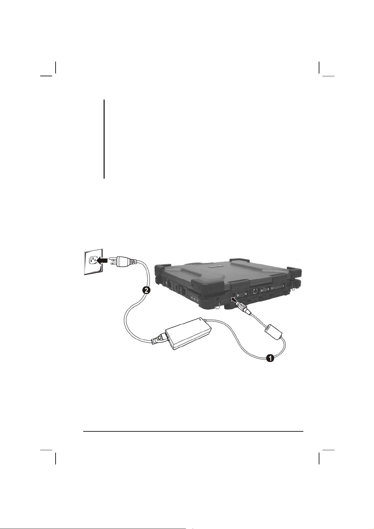
Connecting to AC Power
The computer operates either on the external AC power or internal
battery power. It is suggested that you use AC power when you start up
the computer for the first time.
CAUTION: Use only the AC adapter included with your computer. Using other AC
1-2 Getting Started
adapters may damage the computer.
Page 13
NOTE:
Power Supply Cord: (optional) Detachable, minimum 1.5 m long. Listed, rated
minimum 125 V, 7 A, having a 2/18 AWG, type SVT flexible cord. One end terminates
with a parallel blade, molded-on, attachments plug with a 7 A, 125 V (NEMA 1-15P)
configuration; other end terminates with a molded-on appliance coupler.
Alternative: (optional) Detachable, maximum 4.5 m (14.76 ft) long. Listed, rated
minimum 250 V, 6 A, having a 3/18 AWG, type SVT flexible cord. One end terminates
with a Tandem blade, grounding, listed molded-on, attachments plug with a 6 A, 250 V
(NEMA 6-15P) configuration; other end terminates with a molded-on appliance
coupler.
1. Make sure the computer is turned off.
2. Plug the DC cord of the AC adapter to the power connector on the
rear side of the co
mputer () .
3. Plug the female end of the AC power cord to the AC adapter and the
end to an electrical outlet () .
male
4. When the AC adapter is connected, the indicator on the AC adapter
lights up,
indicating that power is being supplied from the electrical
outlet to the AC adapter and onto your computer. Now, you are ready
to turn on the computer.
Getting Started 1-3
Page 14
CAUTION:
When you disconnect the AC adapter, disconnect from the electrical outlet first and
then from the computer. A reverse procedure may damage the AC adapter or the
computer.
When unplugging the connector, always hold the plug head. Never pull on the cord.
NOTE: When the AC adapter is connected, it also charges the battery pack. For
information on using battery power, see Chapter 3.
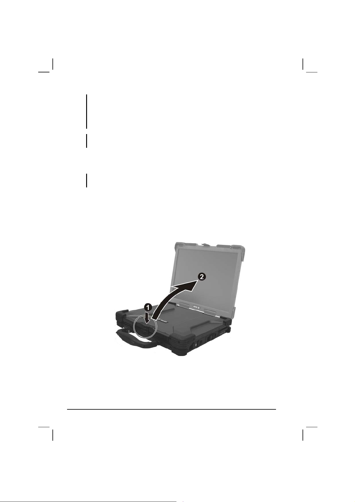
Opening the Cover
CAUTION: Be gentle when opening and closing the cover. Opening it vigorously or
slamming it shut could damage the computer.
1. Open the top cover by pushing on the top portion of the cover latch,
and then pulling on the bottom portion of the cover latch.
2. Lift up the cover. You can tilt the cover forward or backward for
optim
al viewing clarity.
1-4 Getting Started
Page 15
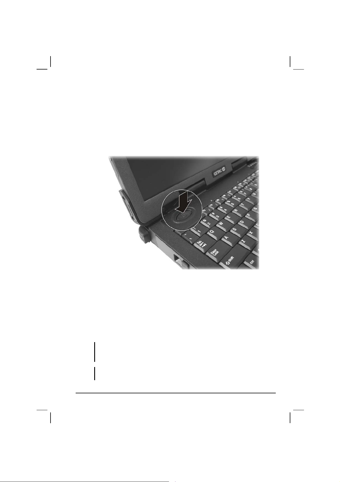
Powering the Computer
Turning On
1. Make sure the computer is connected to AC power.
2. Press the power button.
3. Each time the computer is turned on, it performs a Power-On Self
Test (POST), and the operating s
start.
ystem such as Windows should
Turning Off
To turn off the computer power, use the “Shut Down” command of your
operating system.
NOTE: There are other ways you can stop the computer so that you will be back to
where you left off when you next turn on the computer. (See “Stopping the Computer”
Getting Started 1-5
in Chapter 2 for information.)
CAUTION: If you have to turn the computer on again immediately after turning it off,
wait for at least five seconds. Turning the computer off and on rapidly can damage it.
Page 16

Taking a Look at the Computer
This section identifies the external components of the computer and
briefly describes the function of each component.
NOTE: Depending on the model you purchased, the appearance of your computer may
not exactly be the same as those shown in this manual.
Right-Side Components
Ref Component Description See Also
Primary
Battery Pack
PC Card Slot
USB Ports
PS/2 Port
Supplies power to your computer when external
po
wer is not connected.
Accepts a PC card for additional functions. P. 4-10
Each of the two ports connects a USB device,
suc
h as a USB floppy drive, USB disk, printer,
digital camera, joystick, and more.
Connects a PS/2 keyboard and/or mouse. P. 4-4
P. 3-5
P. 4-3
1-6 Getting Started
Page 17

Left-Side Components
Ref Component Description See Also
CD/Combo/
DVD Dual
Drive
Secondary
Battery Pack
Hard Disk
Drive Slot
Accepts a compact disc (C
loading software, accessing data, and playing
music/video.
You can purchase a secondary battery pack that
sup
plies power to your computer when external
power is not connected.
Inside is the hard disk drive of your computer. P. 2-14
D) for installing or
P. 2-17
P. 3-6
Getting Started 1-7
Page 18

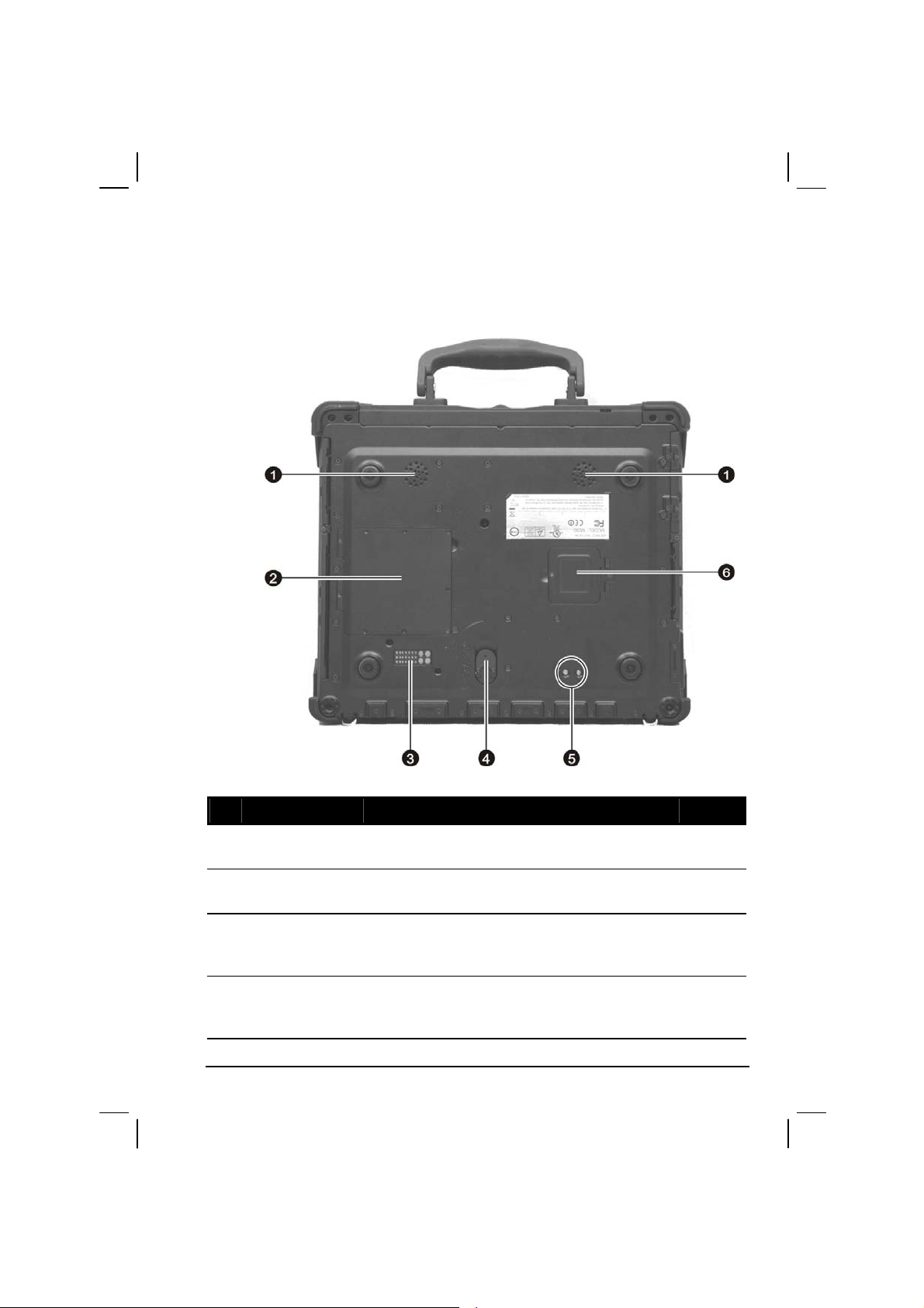
Rear Components
Ref Component Description See Also
IR Port
Power
Connector
Serial Port
RJ-11
Connector
RJ-45
Connector
VGA Port
Parallel Port
Audio Output
Connector
Microphone
Connector
Connects an IrDA-compliant device fo r wire le ss
d
ata transfer.
Connects the AC adapter. P. 1-3
Connects a serial device, such as an external
m
odem.
Connects the telephone line. P. 2-29
Connects the LAN cable. P. 2-25
Connects an external monitor. P. 4-2
Connects a parallel device, such as a printer. P. 4-5
Connects a set of headphones, external speakers
wi
th amplifier, an audio recording device for
audio output.
Connects an external microphone. P. 2-24
P. 4-7
P. 4-6
P. 2-24
1-8 Getting Started
Page 19

Front Components
Ref Component Description See Also
Top Cover
Latch
Kensington
Lock
Touchscreen
Pen (option)
Handle
Locks the top cover. P. 1-4
Locks the computer to a stationary object for
security.
Provides a convenient way to use the
t
ouchscreen. Can be stretched for better grip and
handling.
Allows you to carry your computer for an easy
gri
p.
P. 7-2
P. 2-12
Getting Started 1-9
Page 20

Ref Component Description See Also
Device
Indicators
Show the current status of the computer’s
devices.
AC power indicator.
Glows green when the computer is using AC
wer.
po
Glows red when the computer, using AC power,
is in
Standby mode.
Battery Charge Indicator
Glows green when the battery is fully charged
and connected to
Glows amber when the battery is being charged.
Battery Power Indicator
Glows green when the computer is using battery
wer.
po
Blinks amber when the battery is almost
co
mpletely discharged.
CD/Combo/DVD Dual drive in-use indicator P. 2-17
Wireless LAN (Local Area Network) indicator P. 2-27
Wireless modem indicator P. 2-30
Wired LAN indicator P. 2-25
AC power.
P. 3-2
P. 3-3
P. 3-7
1-10 Getting Started
Page 21
Bottom-Side Components
Ref Component Description See Also
Stereo Speaker
Set
Memory Slot
Docking
Connector
(POGO)
Release Knob
Getting Started 1-11
Sends out sound and voice from the computer. P. 2-20
Contains the memory slot for expanding the
me
mory size of your computer.
For connecting to a Port Replicator / car mount
(both are a
Allows you to remove the CD/Com bo/DVD Dual
dri
ve as well as eject the secondary battery pack
(option).
vailable as an option).
P. 4-12
P. 2-14
P. 3-6
Page 22

Ref Component Description See Also
???
SIM Card Slot
???
Contains the SIM card slot for using the GPS
fu
nction.
P. 2-26
1-12 Getting Started
Page 23
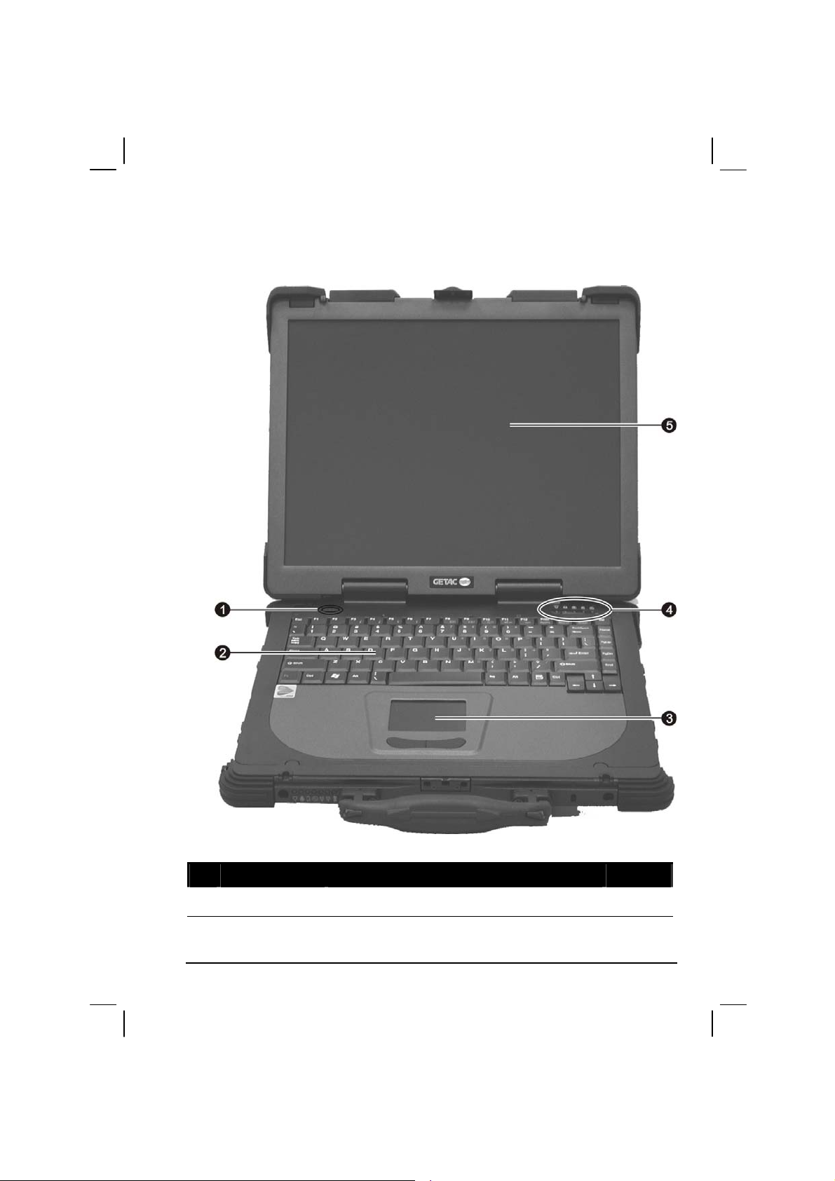
Top-open Components
Ref Component Description See Also
Power Button
Getting Started 1-13
Turns the computer power ON and OFF. P. 1-5
Page 24

Ref Component Description See Also
Keyboard
Serves as the data input device of the computer. P. 2-4
Touchpad
Device
Indicators
LCD Screen
Serves as the pointing device of the computer. P. 2-9
Show the current status of the computer’s
devi
ces.
Power On Indicator
Glows green when the computer is on.
Glows red when the computer is in Standby
mode.
Hard Disk Drive Indicator
Blinks green when the hard disk drive is active.
Blinks red when the hard disk heater is on.
Scroll Lock indicator P. 2-4
Num Lock indicator P. 2-4
Caps Lock indicator P. 2-4
Displays the output of the computer.
C
an also have the optional touchscreen
function.
P. 1-5
P. 2-14
P. 2-21
P. 2-12
1-14 Getting Started
Page 25

Where to Go from Here
As your computer is ready for operation, you may want to do any of the
following now:
For this purpose… Do this…
To know more about the computer… Go on to the next chapter.
To install the operating system if your
dealer has not already done so…
To know more about the operating
system…
To install the drivers if your dealer has
not already done so…
To charge the battery pack for the first
time…
See the operating system manual.
Read the operating system manual.
See Chapter 6.
See “Charging the Battery Pack” in
Chapter 3.
Getting Started 1-15
Page 26

1-16 Getting Started
Page 27

CHAPTER
Operating Your Computer
This chapter provides information about the use of the computer.
If you are new to computers, reading this chapter will help you learn the
operating basics. If y
notebook computers, you may choose to read only the parts containing
information unique to your computer.
Described in this chapter are the operating basics of these co
Keyboard
Touchpad
Touchscreen
ou are already a computer user but are new to
mponents:
2
Hard disk drive
Optical drive
And these features:
Starting and stopping the computer
Video features
Audio features
Communication features
Page 28

Starting and Stopping the Computer
There are a number of ways to start and stop the computer.
Starting the Computer
You always start the computer using the power button.
A computer starts up with an operating system (OS) existing on the
storage device such as the hard disk; or
respective modules installed. The computer will automatically load the
OS after you turn it on. This process is called booting.
NOTE: An operating system is the platform for all your software application programs to
run on. The most widely used operating system today is Microsoft Windows.
from a CD disc if you have the
Stopping the Computer
When you finish a working session, you can stop the computer by turning
off the power or leaving the computer in Standby or Hibernation mode:
To stop in
this mode…
Off Follow the shutdown procedure of your
operating system. This can prevent loss of
unsaved data or damage to your software
programs.
If the system is locked up because of
dware or software problems, press the
har
power button at least 4 seconds to turn off
the computer.
Standby
Depending on your settings in Windows,
you ca
n place the computer in Standby
mode by:
• Clo
• Pressi
• Pressi
sing the display cover
Do this… To start up or
resume again
Press the power
but
Press any key.
ng Fn+F10
ng the power button
ton.
2-2 Operating Your Computer
Page 29

To stop in
this mode…
Hibernation
Depending on your settings in Windows,
you ca
n place the computer in
Do this… To start up or
resume again
Press the power
but
Hibernation mode by:
• Clo
• Pressi
• Pressi
sing the display cover
ng Fn+F10
ng the power button
If you choose to stop in Standby or Hibernation mode, you can return to
where you left off the next time you start up the computer. (See “Power
Management” in Chapter 3 for more information.)
ton.
Operating Your Computer 2-3
Page 30

Using the Keyboard
NOTE: Your computer features backlight for your keyboard to help you see the
keyboard keys during poor lighting conditions. Press Fn+F1 to turn it on/off (see Hot
Keys later in this chapter).
Your keyboard has all the standard functions of a full-sized computer
keyboard plus a
Fn key added for specific functions.
The standard functions of the keyboard
can be further divided into four
major categories:
Typewriter keys
Cursor-control keys
Numeric keys
Function keys
Typewriter Keys
Typewriter keys are similar to the keys on a typewriter. Several keys are
added such as the
the lock keys (
corresponding indicators light up.
The Control/Alternate key is normally used in combination with other
key
s for program-specific functions. The Escape key is usually used for
stopping a process. Examples are exiting a program and canceling a
command. The function depends on the program you are using.
Ctrl, Alt, Esc, and lock keys for special purposes. When
Caps Lock, Num Lk, and Scroll Lk) are pressed, their
2-4 Operating Your Computer
Page 31

Cursor-Control Keys
NOTE: The word “cursor” refers to the indicator on the screen that lets you know
exactly where on your screen anything you type will appear. It can take the form of a
vertical or horizontal line, a block, or one of many other shapes.
Numeric Keypad
A 15-key numeric keypad is embedded in the typewriter keys as shown
next:
Numeric keys facilitate entering of num
Lock is on, the numeric keys are activated; meaning you can use these
keys to enter numerals.
bers and calculations. When Num
Operating Your Computer 2-5
Page 32

NOTE:
When the numeric keypad is activated and you need to type the English letter in the
keypad area, you can turn Num Lock off or you can press Fn and then the letter
without turning Num Lock off.
Some software may not be able to use the numeric keypad on the computer. If so,
use the numeric keypad on an external keyboard instead.
Euro Symbol
You can press the Euro dollar sign on the keyboard.
To press the Euro sign on the keyboard, hold down either of the Alt
keys and type
To press the Euro sign on an UK keyboard, hold down the Alt Gr key
and press
0128 on the numeric keypad of your keyboard.
4 (which has an Euro sign on it).
Windows Keys
The keyboard has two keys that perform Windows-specific functions:
Windows Logo key and
The
Windows Logo key opens the Start menu and performs
Application key.
software-specific functions when used in combination with other keys.
The
Application key usually has the same effect as a right mouse
click. (See your Windows manual for more information.)
Function Keys
On the top row of the keys are the function keys: F1 to F12. Function keys
are multi-purpose keys that perform functions defined by individual
programs.
2-6 Operating Your Computer
Page 33

Fn Key
The Fn key, at the lower left corner of the keyboard, is used with another
key to perform the alternative function of a key. The letter “Fn” and the
alternative functions are identified by the color of blue on the keytop. To
perform a desired function, first press and hold
Fn, then press the other
key.
Hot Keys
Hot keys refer to a combination of keys that can be pressed any time to
activate special functions of the computer. Most hot keys operate in a
cyclic way. Each time a hot key combination is pressed, it shifts the
corresponding function to the other or next choice.
You can easily identify the hot keys with the icons imprinted on the
keytop. The hot keys are described next.
Key Description
Switches the optional keyboard backlight function on/off with
10
levels of brightness in-between.
Decreases the sound volume.
Increases the sound volume.
Decreases the LCD brightness.
Increases the LCD brightness.
Switches the LCD backlight on and off
Switches the LCD on and off.
Operating Your Computer 2-7
Page 34

Key Description
Switches the display output to one of the following when an
external de
Upon booting the system with CRT:
LCD CRT
LCD & CRT
NOTE:
Fn+F9 will not work when playing a DVD/MPEG movie.
Using the VGA utility’s “Graphics Properties” to switch the
Display switching when in full screen (maximize view)
If the display mode is set to 256 colors or lower, or in DOS
This function only applies to Plug & Play CRT monitors.
Serves as the sleep button that yo
Power Management. (See the “Power Management” in
Chapter 3.)
Switches the wireless LAN radio on and off.
vice is connected.
display output is not allowed.
DOS mode is not allowed.
mode, there will be only two modes for selecting: CRT only
and LCD & CRT.
u can define with Windows’
Switches the optional GPS function on and off.
2-8 Operating Your Computer
Page 35

Using the Touchpad
CAUTION: Do not use a sharp object such as a pen on the touchpad. Doing so may
damage the touchpad surface.
NOTE: For optimal performance of the touchpad, keep your fingers and the pads clean
and dry. When tapping on the pad, tap lightly. Do not use excessive force.
The touchpad is a pointing device that allows you to communicate with
the computer by controlling the location of the pointer on the screen and
making selection with the buttons.
The touchpad consists of a rectangular pad and two buttons. To use the
touchpad, pla
ce your forefinger or thumb on the pad. The rectangular pad
acts like a miniature duplicate of your display. As you slide your fingertip
across the pad, the pointer (also called cursor) on the screen moves
accordingly. When your finger reaches the edge of the pad, simply
relocate yourself by lifting the finger and placing it on the other side of
the pad.
Operating Your Computer 2-9
Page 36

Here are some common terms that you should know when using the
touchpad:
Term Action
Point Move your finger on the pad until the cursor points to the
selection on the screen.
Click Press and release the left button.
–or–
Tap gently anywhere on the pad.
Doubleclick
Drag
and
drop
Scroll To scroll is to move up and down or left and right in the working
TABLE NOTE: If you swap the left and right buttons, “tapping” on the touchpad
as an alternative method of pressing the left button will no longer be valid.
Press and release the left button twice in quick succession.
–or–
Tap twice on the pad rapidly.
Press and hold the left button, then move your finger until you
reach your destination (drag). Finally, release the button (drop)
when you finish dragging your selection to the destination. The
object will drop into the new location.
–or–
Gently tap twice on the pad and on the second tap, keep your
er in contact with the pad. Then, move your finger across the
fing
pad to drag the selected object to your destination. When you lift
your finger from the pad, the selected object will drop into place.
area on the screen.
To move vertically, place your finge
pad and slide your finger up and down along the edge. To move
horizontally, place your finger on the bottom edge of the pad and
slide your finger left and right.
This function works only after you install the touchpad driver
plied with the computer and it may not work for all
sup
applications.
r on the right edge of the
2-10 Operating Your Computer
Page 37

Configuring the Touchpad
You may want to configure the touchpad to suit your needs. For example,
if you are a left-handed user, you can swap the two buttons so that you
can use the right button as the left button and vise versa. You can also
change the size of the on-screen pointer, the speed of the pointer, and so
on.
To configure the touchpad, you can use the standard Microsoft or IBM
PS/2 driver if
you are using Windows.
Operating Your Computer 2-11
Page 38

Using the Touchscreen (Optional)
NOTE: Make sure the “Serial Port COM3 (Touchscreen)” item is set properly in the
SCU program. (See “Advanced Menu” in chapter 5 for information.)
CAUTION: Do not use a sharp object such as a ballpoint pen or pencil on the
touchscreen. Doing so may damage the touchscreen surface. Use the included
touchscreen pen (option) located on the handle.
The touchscreen is a touch-sensitive device that allows you to
communicate with the computer by controlling the location of the pointer
on the screen and making selection with the buttons.
The touchscreen needs a special device driver support that allows you to
easily
use the computer without a mouse or touchpad. (For information
on installing the driver, see Chapter 6.)
2-12 Operating Your Computer
Page 39

Here are some common terms that you should know when using the
touchscreen:
Term Action
Click/Point Tap gently on the touchscreen.
Double-click Tap twice on the touchscreen rapidly.
Drag and
drop
Scroll To scroll is to move up and down or left and right in the
Press lightly on the touchscreen and move your finger
until you reach your destination (drag). Finally, release
your finger (drop) when you finish dragging your selection
to the destination. The object will drop into the new
location.
working area on the screen.
To move vertically, place your finger on the right edge of
th
e touchscreen and slide your finger up and down along
the edge. To move horizontally, place your finger on the
bottom edge of the touchscreen and slide your finger left
and right.
This function works only after you install the touchscreen
d
river supplied with the computer and it may not work for
all applications.
Operating Your Computer 2-13
Page 40

Using the Hard Disk Drive
Your computer comes with a removable hard disk drive as drive C. A
hard disk dri
magnetic storage platters inside it. It is where your operating system and
application software programs are stored.
Your hard disk drive is a 2.5-inch IDE (Integrated Drive Electronics) hard
disk drive. T
storage by integrating all the control circuitry necessary for operation
directly onto the drive itself. This allows the drive manufacturer to
carefully optimize drive performance.
ve is a storage device with non-removable, rotating,
his type of drive embodies the latest in fast, reliable mass
The system comes with a built-in heater that automatically
low temperature operation. The HDD indicator (
heater is on.
NOTE:
To use the HDD heater feature, the MTCCTRL driver supplied with your computer
must be installed (see chapter 6 for details).
Make sure the “HDD Heater” item is set properly in the SCU program. (See
“Advanced Menu” in chapter 5 for information.)
CAUTION:
Make regular backups of your data files from your hard disk drive to USB disks or
other storage media.
Never try to remove or install the hard disk drive while the computer is powered on.
Doing so can result in loss of data, and can damage the computer and the hard disk
drive’s sensitive circuitry.
Never turn off or reset the computer while the hard disk drive in-use indicator is on.
Replacing the Hard Disk Drive
To replace the hard disk drive:
4. Make sure that system power is off.
5. Remove the battery pack (see chapter 3 for details).
turns on for
) blinks red when
6. Locate the hard disk drive slot on the left side of the system.
2-14 Operating Your Computer
Page 41
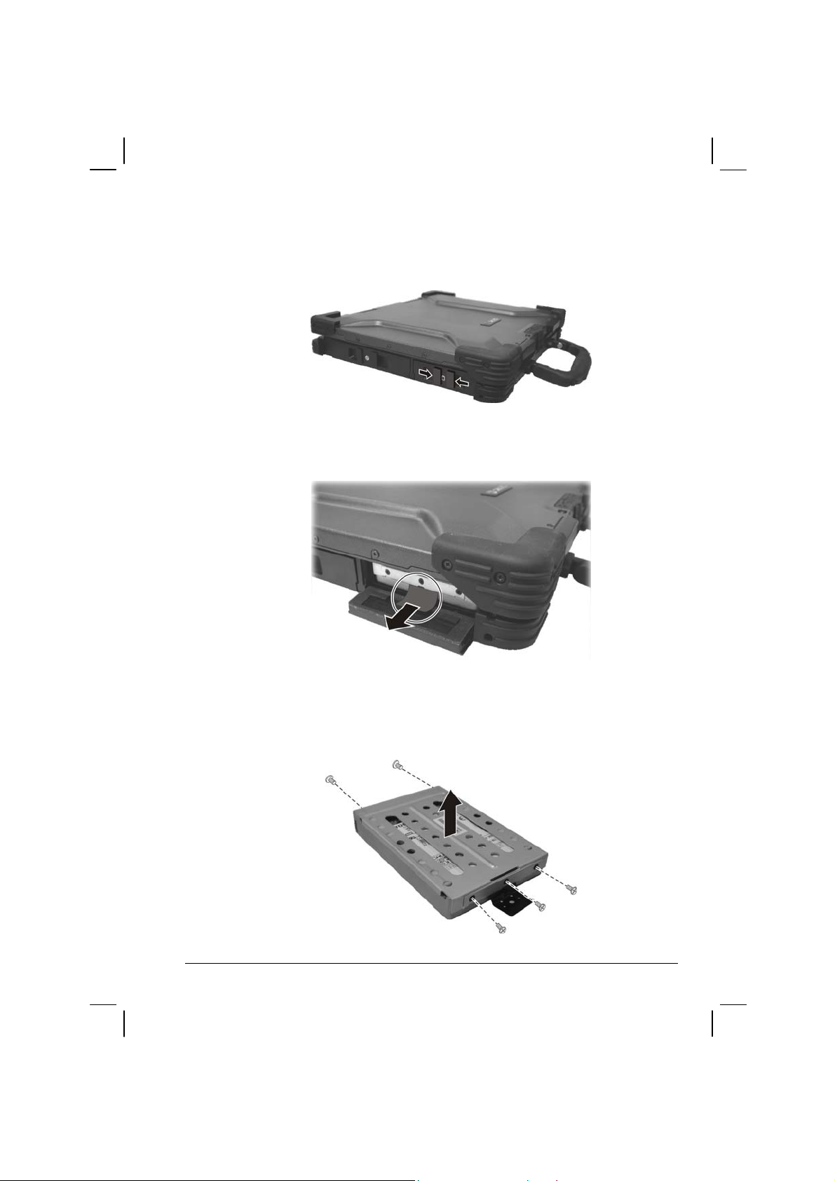
7. Open the hard disk drive slot cover by pressing on both sides of the
release latch using your thumb and index fingers.
8. Pull on the ribbon film to remove the hard disk drive compartment.
9. Remove the three front and two rear screws securing the hard disk
drive to the c
ompartment and remove the compartment cover.
Operating Your Computer 2-15
Page 42

10. Place the new hard disk drive into the compartment and tighten the
three front and two rear screws.
11. Slide the HDD compartment into the slot until it reaches the end.
12. Close the hard disk drive slot cover to secure the HDD compartment.
2-16 Operating Your Computer
Page 43

Using the Optical Drive
Depending on the model, your computer comes with a CD, Combo drive,
or DVD dual recorder located on the left side of the computer. This drive
is usually configured as drive D.
The drive uses removable 5.25-inch silver discs, which look like standard
m
usic discs. It is an ideal medium to use for distributing multimedia
because of the huge amount of data that a disc can store.
Depending on the model, your drive is one of the following:
CD drive can read CDs, audio CDs, CD-R, and CD-RW discs.
Combo drive can work both as a CD drive (reading DVD discs in
addition to CDs, audio CDs and CD-R/-RW discs), and also as a CD
recorder (writing to CD-R/-RW discs).
DVD Dual drive besides the Combo drive function, can write to
DVD+R/+RW/-R/-RW discs.
NOTE: If the CD/Combo/DVD Dual drive would be operating for more than half an hour
(such as showing a DVD title), use the AC power source instead of the battery. If not,
the battery may run out of power before the operation is complete.
CAUTION:
When inserting a disc, do not use force.
Make sure the disc is correctly inserted into the tray, and then close the tray.
Do not leave the CD tray open. Also, avoid touching the lens in the tray with your
hand. If the lens becomes dirty, the disc may malfunction.
Do not wipe the lens using materials with rough surface (such as paper towel).
Instead, use a cotton swab to gently wipe the lens.
FDA regulations require the following statement for all laser-based devices:
“Caution, Use of controls or adjustments or performance of procedures other than
those specified herein may result in hazardous radiation exposure.”
NOTE: The CD/Combo/DVD Dual drive is classified as a Class 1 laser product. This
label is located on the drive.
Operating Your Computer 2-17
Page 44
NOTE: For Combo/DVD Dual drive only.
This product incorporates copyright protection technology that is protected by method
claims of certain U.S. patents and other intellectual property rights owned by
Macrovision Corporation and other rights owners. Use of this copyright protection
technology must be authorized by Macrovision Corporation, and is intended for home
and other limited viewing uses only unless otherwise authorized by Macrovision
Corporation. Reverse engineering or disassembly is prohibited.
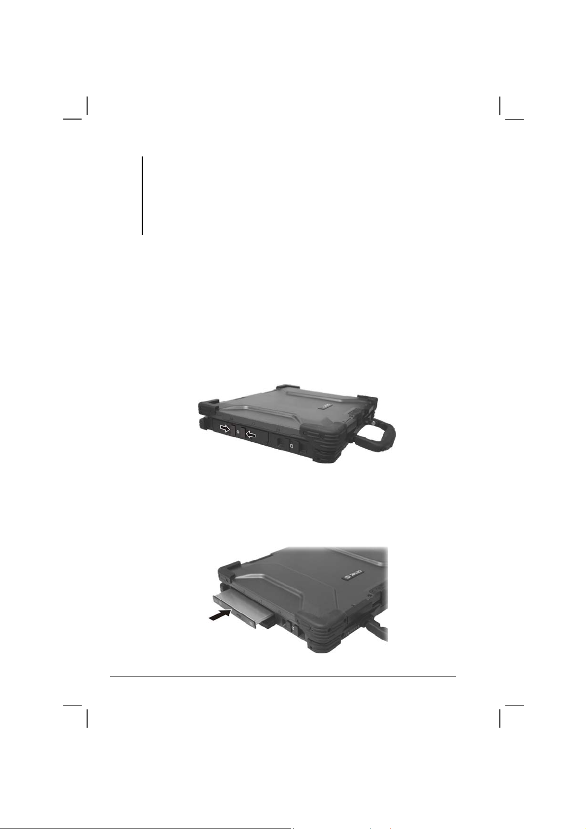
Installing the Optical Drive
To install the optical drive:
1. Make sure that the computer is off.
2. Locate the optical drive bay on the left side of the computer.
3. Open the optical drive bay cover by pressing on both sides of the
release latch
using your thumb and index fingers.
If no module is inside the drive bay
4. Insert the optical drive into the drive bay.
2-18 Operating Your Computer
Page 45

5. Close the optical drive bay cover to secure the drive in place.
If another module is inside the drive bay
4. Check to see if any other module is installed in the optical drive bay.
If no other module is inside, proceed directly to step 10.
5. Close the optical drive bay cover.
6. Gently place the computer upside down.
7. Open the optical drive bay cover again by pressing on both sides of
the release latch using
8. Lift up the handle of the optical drive release knob and turn it
counter-clockwise.
your thumb and index fingers.
9. Pull out the existing module.
Operating Your Computer 2-19
Page 46
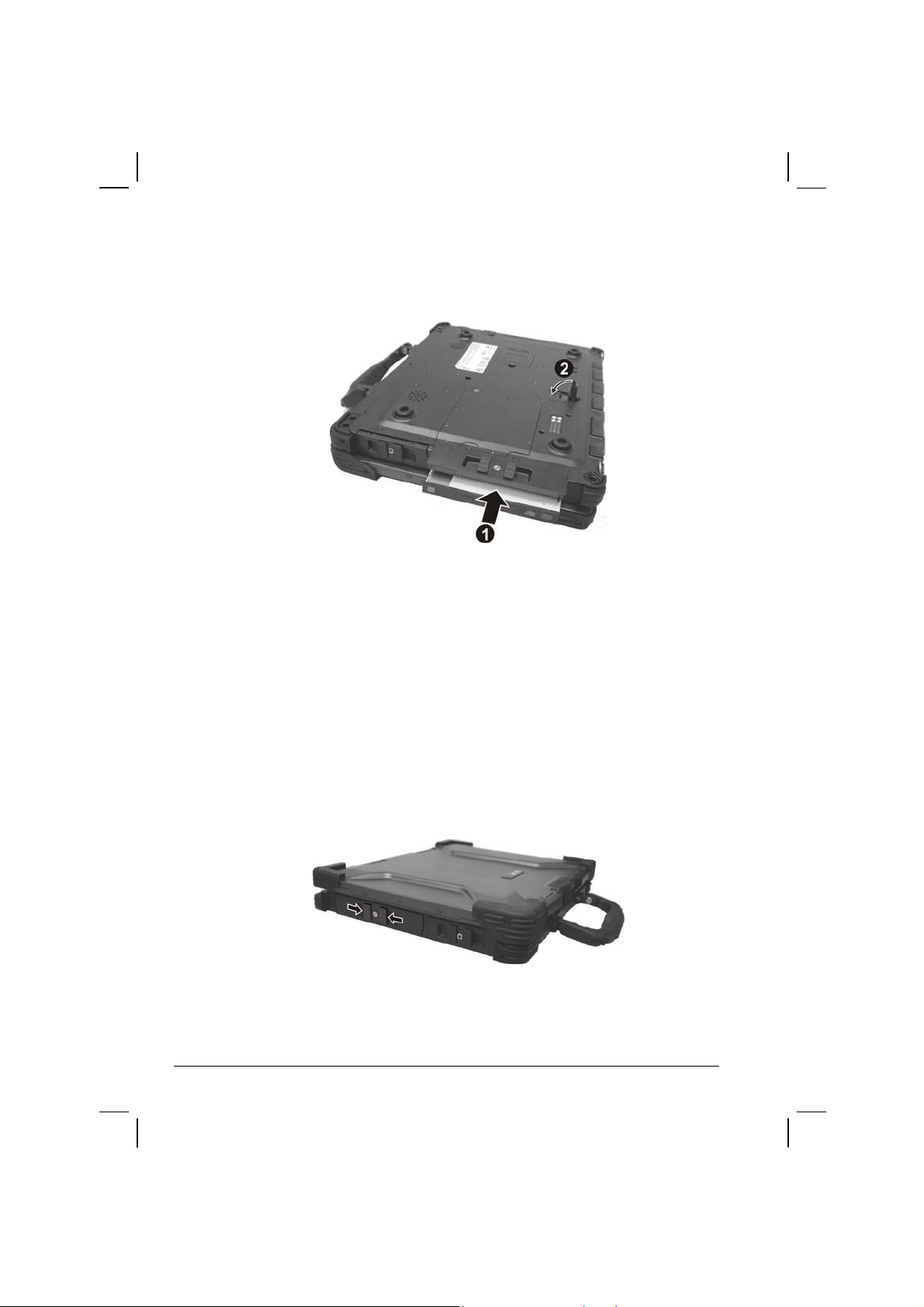
10. Insert the optical drive into the drive bay () and return the release
knob ().
11. Close the optical drive bay cover to secure the drive in place.
Inserting and Removing a Disc
Follow this procedure to insert or remove a disc.
1. Turn on the computer.
2. Locate the optical drive bay on the left side of the computer.
3. Open the optical drive bay cover by pressing on both sides of the
release latch
4. Press the eject button and the drive tray will slide out partially. Gently
pull on it unti
using your thumb and index fingers.
l it is fully extended.
2-20 Operating Your Computer
Page 47

5. To insert a disc, place down the disc in the tray with its label facing
up. Slightly press the center of the disc until it clicks into place.
To remove a disc, hold the disc by its outer edge and lift it up from the
.
tray
6. Gently push the tray back into the drive.
NOTE: In the unlikely event that you are unable to release the drive tray by pressing the
eject button, you can manually release the disc. (See “Optical Drive Problems” in
Chapter 8.)
Operating Your Computer 2-21
Page 48

Using the Video Features
The video subsystem of your computer features:
14.1-inch TFT (Thin-Film Transistor) color LCD display with
1024
×768 XGA (Extended Video Graphics Array) resolution, or
15-inch TFT color LCD display with 1400
Extended Video Graphics Array) resolution.
64 MB shared with system memory.
LCD backlight to help you see the display during poor lighting
conditions. Press Fn+F7 to turn it on/off (see Hot Keys in this
chapter).
Simultaneous display on LCD and external monitor, which is useful
when you have a presentation as you can control the screen from your
computer and face the audience at the same time.
×1050 SXGA+ (Super
Dual view capability, which allows you to expand your desktop on
the screen to another display device so that you have more desktop
space to work on.
Power Management.
Touchscreen function (option).
High contrast LCD display (option for 14.1-inch panel).
NOTE:
To take advantage of the enhanced video capabilities and before using the dual
view capability, the device driver supplied with your computer must be installed
(see chapter 6 for details).
The computer enters Standby or Hibernation mode when the LCD is closed. If you
want to use the computer with the LCD closed, set None to the “When I close the lid
of my portable computer” option in the Power Management Properties. Thus the
computer does not enter Standby or Hibernation mode when the LCD is closed.
Configuring the Display Modes
NOTE: When using CRT only, the resolution would depend on the supported resolution
by the CRT.
2-22 Operating Your Computer
Page 49

Your computer has been set to a default resolution and number of colors
before shipment. You can view and change display settings through your
operating system. See your operating system documentation or online
help for specific information.
For displaying in higher resolutions,
you can connect an external CRT
monitor that supports higher resolutions. (See “Connecting an External
Monitor” in Chapter 4 for more information.)
The following table lists the display modes supported by your computer.
Display Mode LCD Only CRT Only Simultaneous Display
Resolution Colors
1024×768
1400×1050
1600×1200
16-bit
32-bit
16-bit
32-bit
16-bit
32-bit
√ √ √
√ √ √
√ √ √
√ √ √
√ √ √
√ √ √
TABLE NOTE:
16-bit = High Color or 65,536 (64 K) colors; 32-bit = True Color 16,770,000 (16 M)
colors.
When using CRT only, the resolution would depend on the supported resolution by
the CRT.
Operating Your Computer 2-23
Page 50

Using the Audio Features
NOTE:
To take advantage of the enhanced audio capabilities, the device driver supplied
with your computer must be installed (see chapter 6 for details).
If you experience interference while recording, try lowering the microphone
recording volume.
The audio subsystem of your computer features:
External audio connectors (
A set of speakers (
) on the bottom side
) on the rear, and
Ways of playing and recording sound vary with the operating system
used. See y
our operating system documentation or online help for
specific information.
2-24 Operating Your Computer
Page 51
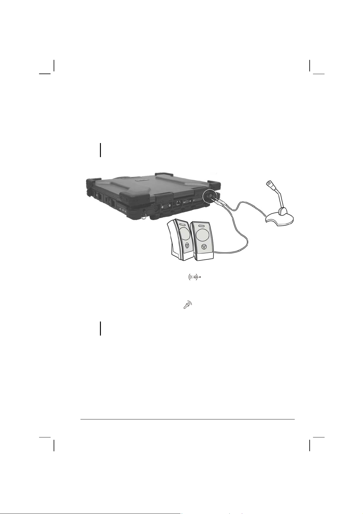
Connecting Audio Devices
For higher audio quality, you can send or receive sound through external
audio devices.
NOTE: After connecting an external audio device, make sure that you specify the use
of the correct audio device in Windows.
Audio Output Connector (
) can be connected to the line-in
connector of powered speakers with built-in amplifiers, headphones,
or earphone set.
Microphone Connector (
) can be connected to an external
microphone for recording voice or sound.
NOTE: When using external speakers/headphones or microphone, you cannot use the
internal one.
Operating Your Computer 2-25
Page 52

Using the Communication Features
Using the LAN
NOTE: To take advantage of the LAN (Local Area Network) feature, the device driver
supplied with your computer must be installed (see chapter 6 for details).
The internal 10/100/1000Base-T Ethernet module allows you to connect
your computer to a network. It supports data transfer rate up to 1000
Mbps.
To connect the network cable to the LAN module, connect one end of the
LAN cable to
the network hub. The LAN indicator (
computer is ready for LAN connection.
the RJ-45 connector on the computer and the other end to
) glows to indicate that the
2-26 Operating Your Computer
Page 53

Using the Wireless LAN (WLAN)
An internal Mini PCI wireless LAN module have been pre-installed by
your computer manufacturer at the factory. This allows you to access
corporate networks or the Internet in a wireless environment.
The WLAN features include:
Peer-to-Peer (Ad-Hoc) and Access Point (Infrastructure) modes
support
WEP (Wired Equivalent Privacy) 64/128-bit data encryption
IEEE 802.11a/b/g standard compliance
Technology 802.11a 802.11b 802.11g
Stated Maximum
Throughput (Mbps)
Data Rates (Mbps) 54, 48, 36, 24, 18,
Band (GHz) 5.15 ~ 5.35 2.412 ~ 2.462 2.4
Modulation
Technology
NOTE: 802.11g mode is backward compatible with 802.11b mode.
To take advantage of the WLAN feature, make sure that the PROSet
driver is installed correctly (see Chapter 6 for details). If your WLAN
module was provided by your dealer instead of the computer
manufacturer, contact your dealer for the correct driver to use.
54 11 54
11, 5.5, 2, 1 54, 36, 18, 9
12, 9, 6
OFDM (Orthogonal
Frequency Division
Multiplexing)
DSSS (Direct
Sequence Spread
Spectrum)
OFDM (Orthogonal
Frequency Division
Multiplexing)
Configuring the WLAN
After driver installation, you can use the WLAN utility to configure and
monitor your WLAN connection. If you are using Windows XP, you can
also use its built-in WLAN utility. Follow this procedure to launch the
WLAN utility in Windows XP:
1. Select Control Panel fro
2. Click Netwo
Operating Your Computer 2-27
rk and Internet Connections.
m the Start menu.
Page 54

3. Click Network Connections, then double-click the Wireless Network
Connection icon
.
4. Click Properties in the
Wireless Network Connection Status dialog
box.
5. You can configure your WLAN settings in the Wireless Network
Connection Properti
es dialog box.
Turning Off/On the WLAN Radio
NOTE: The FAA (Federal Aviation Agency) has deemed it unsafe to operate wireless
devices in aircraft as this may interfere with flight safety. Remember to turn off wireless
LAN when using your computer in the airplane.
Your computer has a built-in Fn+F11 WLAN hot key to switch the WLAN
on/off (see “Hot Keys” in Chapter 2). The WLAN indicator (
to indicate that the computer is ready for WLAN connection.
If you need to temporarily turn off the radio, press
network connection, press
Fn+F11 again.
It takes approximately 30 seconds for your com
Fn+F11. To resume
puter to make a successful
WLAN connection and approximately 10 seconds to disconnect.
Connecting to a Wireless Network
To connect to a wireless network:
) glows
1. Make sure that the WLAN radio is on.
2. Click Start and then All Programs.
3. Click Intel PROSet Wirel
2-28 Operating Your Computer
ess and then Intel PROSet Wireless.
Page 55
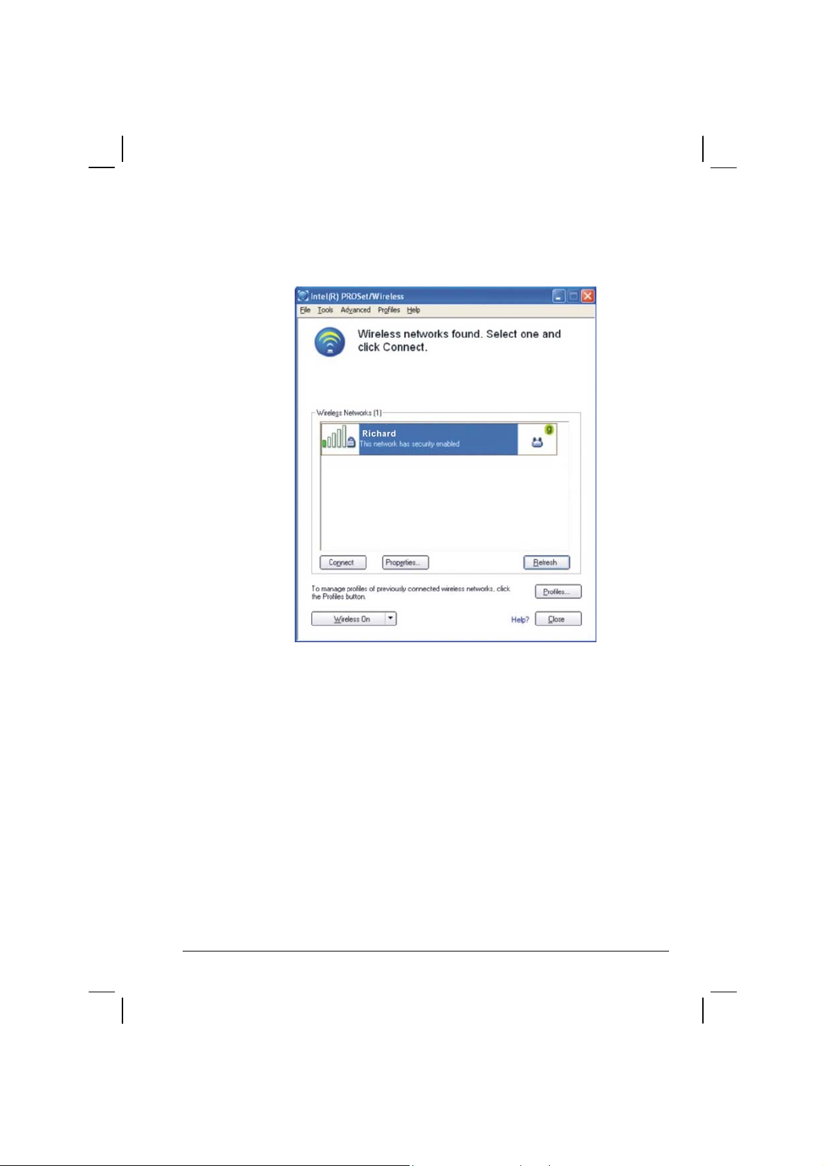
4. If any wireless network is detected, the following window appears on
screen.
5. Click to select a wireless network to connect to, and then click
Connect.
6. Depending on the settings, you may be asked to enter a wireless
security
password (encryption key).
For more information on the Intel PROSet Wireless utility, click Help? in
the Intel(R) PROSet/Wireless window.
Operating Your Computer 2-29
Page 56

Using the Modem
NOTE: To take advantage of the modem feature, the device driver supplied with your
computer must be installed (see chapter 6 for details).
The internal 56 K fax/data modem allows you to use the telephone line to
communicate with others by fax, email, or connect to an online service or
bulletin board.
To connect the telephone line to the modem, connect one end of the
m
odem cable to the RJ-11 connector on the computer and the other end to
the phone line.
NOTE:
When using communication software, you may have to disable power
management.
Set the COM port of the modem to COM3.
Set parameters such as modem speed (baud rate) and line type (pulse dialing or
tone dialing).
Do not enter Standby mode when using communication software.
2-30 Operating Your Computer
Page 57

Connecting Using GPRS
Your computer can receive General Packet Radio Services (GPRS), a
high-speed data-only service that transmits data over a mobile telephone
network. In addition, GPRS provides permanent on-line connection.
To use GPRS, you must have a subscription t
provider that supports GPRS.
To connect to a GPRS network, you must configure a connection for that
service on yo
ur computer.
o the function with a service
Using the GPS (Optional)
NOTE: To take advantage of the GPS feature, the USB-to-COM driver supplied with
your computer must be installed (see chapter 6 for details).
Navigation and positioning are crucial to so many activities. To try to
figure out where you are and where you are going, you need GPS
technology. The Global Positioning System (GPS) is a worldwide
radio-navigation system.
Turning On/Off the GPS
Your computer has a built-in Fn+F12 GPS hot key to switch the GPS
on/off (see “Hot Keys” in this chapter).
Using Bluetooth (Optional)
NOTE: To take advantage of the Bluetooth feature, the Bluetooth driver supplied with
2-32 Operating Your Computer
your computer must be installed (see chapter 6 for details).
Depending on your model, your computer may incorporate the Bluetooth
capability for short-range (about 10 meters) wireless communications
between devices without requiring a cable connection.
With Bluetooth, data can be transm
briefcases as long as two devices are within range. By default, your
computer’s Bluetooth feature is active (always ON) upon booting your
computer and is in the general discoverable and pairable mode.
itted through walls, pockets and
Page 58

The status of the Bluetooth connection is indicated by the Bluetooth icon
located in the system tray in the lower-right part of the screen.
Status Icon
On
Connected
(blue with white logo)
(blue with green logo)
You can use the Bluetooth Utility to configure Bluetooth connection
settings and transfer files.
Connecting to Another Bluetooth Device
1. Make sure that the target Bluetooth device is turned on, discoverable
and within close range. (See the documentation that came with the
Bluetooth device.)
2. Double-click the
Bluetooth, then Add New Connection . . .
Or right-click the
icon, then click on New Connection or click on
icon, and then click on Add New Connection.
or
Operating Your Computer 2-33
Page 59
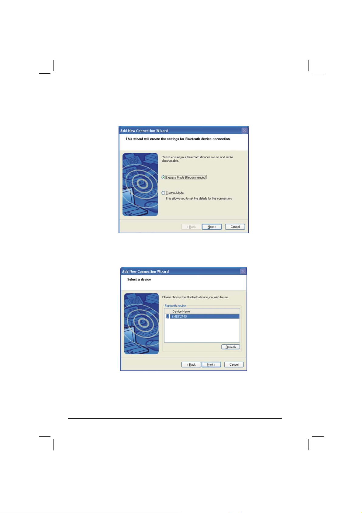
3. The Add New Connection Wizard window appears. Select Express
Mode (Recommended), then click on Next.
4. Select the device to connect to and click on Next.
5. Depending on the type of Bluetooth device that you want to connect
to,
you will need to enter the pertinent information.
2-34 Operating Your Computer
Page 60

Sending a File
1. Right-click the icon, and then click Wireless File Transfer. The
following screen appears.
2. In the Wireless File Tran
to send. The file(s) will show on the File/Folder window.
3. Click the target device from the Tr
then click Send to start the transfer procedure.
Operating Your Computer 2-35
sfer window, click Add to browse for the file
ansfer-enabled device window, and
Page 61

For detailed information on using the Bluetooth Utility, see the Bluetooth
Utility Help on your computer by clicking on Help, then Help . . .
2-36 Operating Your Computer
Page 62

HELP FOR ModuleSW PROGRAM
Version: ModuleSW 1.0.1.9
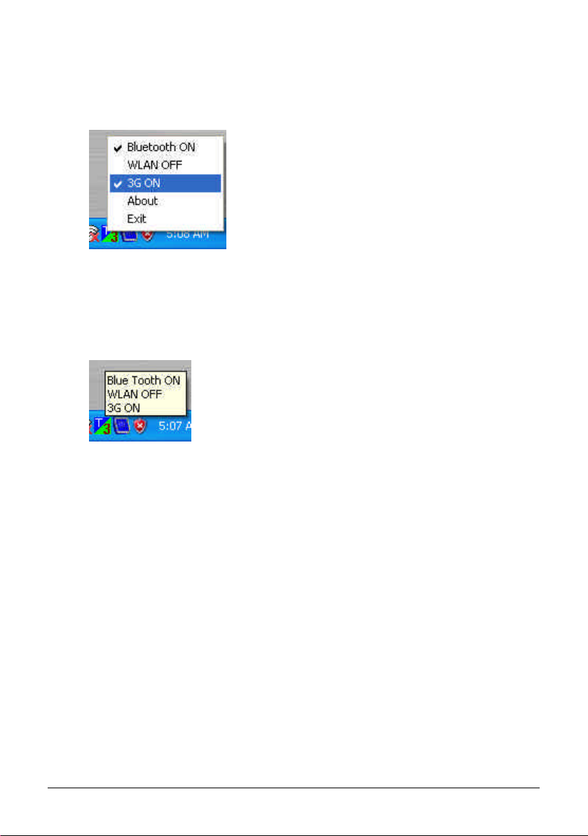
The ModuleSW program can to set BlueTooth/WirelessLan/3G modules
power ON or OFF and keep the state to system startup.
There are 5 subitem can be selection. The menu and subitem as follow:
The user can select and click BlueTooth or WirelessLan(WLAN) or 3G
subitem to switch module power state.
For example:
If user select and click "3G ON" subitem . ModuleSW will switch 3G module
power ON state to OFF and When system startup(or restart), ModuleSW
will keep 3G module to power OFF state.
Operating Your Computer 2-37
Page 63
If user select and click "3G OFF" subitem . ModuleSW will switch 3G
module power OFF state to ON and When system startup(or
restart) ,ModuleSW will keep 3G module to power ON state.
If user move cursor to ModuleSW tray-icon than show
BuleTooth/WirelessLan/3G module power state.
2-38 Operating Your Computer
Page 64

CHAPTER
Managing Power
Your computer operates either on external AC power or internal battery
power.
This chapter tells you how you can effectively manage power. To
maintain optimal battery
battery in the proper way.
The topics in this chapter include:
What is an AC adapter
How to charge the battery pack
When and how to initialize the battery pack
performance, it is important that you use the
3
How to check the battery level
How to replace the battery pack
What happens when the battery is low and what actions to take
What is Power Management
How to save power
Page 65

AC Adapter
CAUTION:
The AC adapter is designed for use with your computer only. Connecting the AC
adapter to another device can damage the adapter.
The AC power cord supplied with your computer is for use in the country where you
purchased your computer. If you plan to go overseas with the computer, consult
your dealer for the appropriate power cord.
When you disconnect the AC adapter, disconnect from the electrical outlet first and
then from the computer. A reverse procedure may damage the AC adapter or
computer.
When unplugging the connector, always hold the plug head. Never pull on the cord.
The AC adapter serves as a converter from AC (Alternating Current) to
DC (Direct Current) power because your computer runs on DC power,
but an electrical outlet usually provides AC power. It also charges the
battery pack when connected to AC power.
The AC adapter operates on any voltage in the range of 100 ~ 240 V AC.
3-2 Managing Power
Page 66

Battery Pack
The battery pack is the internal power source for the computer. It is
rechargeable using the AC adapter.
The operating time of a fully charged battery pack depends on how you
are using the
you will experience a shorter operating time.
NOTE: Care and maintenance information for the battery is provided in the “Battery
Pack Guidelines” section in Chapter 7.
Charging the Battery Pack
NOTE:
Charging will not start if the battery pack’s temperature is or above 60 °C (140 °F).
The charging process will stop and the Battery Charge Indicator flashes amber and
green alternatively when the battery’s temperature gets above 60 °C (140 °F). If
this happens, the battery pack may be damaged. Please contact your dealer.
During charging, do not disconnect the AC adapter before the battery has been fully
charged; otherwise you will get a prematurely charged battery.
To charge the battery pack, connect the AC adapter to the computer and
computer. When your applications often access peripherals,
an electrical outlet. The Battery Charge Indicator (
) on the computer
glows amber to indicate that charging is in progress. You are advised to
keep the computer power off while the battery is being charged. When the
battery is fully charged, the Battery Charge Indicator glows green.
The charging times are as follows:
Charging Time
Battery Type
7200 mAh /
11.1 V
CAUTION: After the computer has been fully recharged, do not immediately disconnect
and reconnect the AC adapter to charge it again. Doing so may damage the battery.
Managing Power 3-3
Computer is Off
2.5 hours
(150 minutes)
Computer is On and in Idle
State as well as when
Computer is Off and
battery pack’s temperature
gets above 45 °C (113 °F)
5.8 hours
(350 minutes)
Page 67

NOTE: The battery level may automatically lessen due to the self-discharge process
(0.21 % per day), even when the battery pack is fully charged (100 %). This happens no
matter if the battery pack is installed in the computer.
Initializing the Battery Pack
You need to initialize a new battery pack before using it for the first time
or when the actual operating time of a battery pack is much less than
expected.
Initializing is the process of fully charging, discharging, and then
charging. It c
1. Make sure the computer power is turned off. Connect the AC adapter
to full
an take several hours.
y charge the battery pack.
2. After the battery pack is fully charged, turn on the computer.
3. Disconnect the AC adapter and leave the computer on until the
battery
is fully discharged. The computer will shut down
automatically, depending on your settings in Windows.
4. Connect the AC adapter to fully charge the battery pack.
Checking the Battery Level
When two batteries exist on the system, the battery’s discharge sequence
is from the optional secondary battery (located on the optical drive bay) to
the primary battery (located on the right side). When the battery charge
on the optional secondary battery falls below 9.1 V, then power usage
will switch to the primary battery. When the battery charge on the
primary battery falls below 9.1 V, then system will shutdown.
NOTE: Any battery level indication is an estimated result. The actual operating time can
be different from the estimated time, depending on how you are using the computer.
You can check the approximate battery level using the battery meter
function of the operating system. To read the battery level in Windows,
click the
icon on the taskbar. (Click the icon if the computer is
using AC power.)
3-4 Managing Power
Page 68

Replacing the Primary Battery Pack
CAUTION:
There is danger of explosion if the battery is incorrectly replaced. Replace the
battery only with the computer manufacturer’s optional battery packs. Discard used
batteries according to the dealer’s instructions.
Do not attempt to disassemble the battery pack.
To replace the primary battery pack, follow these steps:
1. Make sure the computer is not turned on or connected to AC power.
2. Locate the battery slot on the right side of the system.
3. Open the slot cover by pressing on both sides of the release latch
using
your thumb and index fingers.
4. Pull on the ribbon strip to remove the battery pack and
replace it with
a new one.
Managing Power 3-5
Page 69

5. Slide the new battery pack all the way into the slot. Make sure to
observe the correct orientation (the ribbon strip must face outward for
future battery back removal).
6. Close the slot cover to secure the battery pack.
Installing the Secondary Battery Pack
If you often rely on battery power for a long period of time while
traveling, you may consider the purchase of an additional battery pack
from your dealer and keep it with you in a fully charged state as a backup.
To install the secondary battery pack, follow these steps:
1. Make sure the computer is not turned on or connected to AC power.
2. Locate the optical drive slot on the left side of the system.
3. Gently place the computer upside down.
4. Open the slot cover by pressing on both sides of the release latch
your thumb and index fingers.
using
5. Lift up the handle of the optical drive release knob and turn it
counter-clockwise.
3-6 Managing Power
Page 70

6. The optical drive will slide out partially. Gently pull on it to remove
it.
7. Slide the secondary battery pack all the way into the slot. Make sure
to observe the correct orientation (the ri
bbon strip must face outward
for future battery pack removal).
8. Close the slot cover to secure the secondary battery
NOTE: The system supports the secondary battery hot-swap function, providing you
the ability to replace the battery even during system on. Hot swap means that you can
remove the secondary battery pack and replace it with another one without significant
interruption to the system (without turning off the system).
Battery Low Signals and Actions
Battery Low occurs when the battery has approximately 10 % (Windows
default setting) of its charge remaining. The computer gives warning
messages and the Battery Power Indicator (
alert you to take actions.
NOTE: You can set up your threshold and signals of Battery Low under Windows.
Immediately save your data upon Battery Low. The remaining operating
time depends on how you are using the computer. If you are using the
audio subsystem, hard or optical drives, PC card, the battery might run
out of charge very quickly.
) blinks amber (orange) to
Managing Power 3-7
Page 71

Always respond to Battery Low by placing your computer on Standby or
Hibernation mode, turning off the computer, or connecting the AC
adapter.
If you do not take any action, the computer will automatically hibernate
and turn
CAUTION:
If you are using a flash PC card, do not access the card during battery low periods.
If you fail to save your data when the battery completely runs out of charge, then
off.
This is because the access may take longer than the time it takes the battery to run
out of charge, thus making your access to the card unsuccessful.
you lose your data.
3-8 Managing Power
Page 72

Power Management
Your computer supports ACPI (Advanced Configuration and Power
Interface) for power management. The power management feature allows
you to reduce the power consumption for energy saving.
With an ACPI-compliant operating system such as Windows 2000 and
Windows XP, power suppl
controlled on an as-needed basis. This allows maximum power
conservation and performance at the same time.
In general, Windows’ power management works in this way:
What… When…
Power to the hard disk is turned off When the hard disk has been idle for a
Power to the display is turned off When the display has been idle for a set
The computer enters Standby mode.
The hard disk and display are turned
off and the entire system consumes
less power.
The computer enters Hibernation
mode. (See the next subsection for
more information.)
* depends on your settings in Windows.
For detailed information on power management, see Windows’ Help.
y to different computer components is
set period.
period.
When the entire system has been idle
for a set period.
When you press Fn+F10. *
When you close the cover. *
When you press the power button. *
When you press the power button. *
When you press Fn+F10. *
When you close the cover. *
Managing Power 3-9
Page 73

Hibernation
Hibernation is a very useful feature. People frequently open many
applications when they use computers. It takes some time to get all these
applications open and running, and normally they all have to be closed
before the system can be turned off.
When you use the hibernation feature, you do not have to close the
applications. The co
the hard disk and then shut down. The next time you turn on your
computer, you return to exactly where you left off.
mputer stores the state of your computer to a file on
3-10 Managing Power
Page 74

Power-Saving Tips
In addition to your computer’s automatic power management, you can do
your part to maximize the battery’s operating time by following these
suggestions.
Do not disable Power Management.
Decrease the LCD brightness to the lowest comfortable level.
Disable the parallel and serial ports if no devices are connected to
these ports. (See “Advanced Menu” in Chapter 5.)
If you work with an application that features wireless connectivity
(LAN/modem/GPS/Bluetooth), exit the application when you finish
using it.
If you have a PC card installed, remove it when not in use. Some PC
cards drain power even while they are inactive.
Turn off the computer when you are not using it.
Managing Power 3-11
Page 75

3-12 Managing Power
Page 76

CHAPTER
4
Expanding Your Computer
You can expand the capabilities of your computer by connecting other
peripheral devices. When using a device, be sure to read the instructions
accompanying the device together with the relevant section in this
chapter.
This chapter gives guidelines on installing and using these devices:
External monitor
USB device
Parallel device
Serial device
IR device
IEEE 1394B device
PC card
Page 77

Connecting an External Monitor
If you want the benefits of a larger display screen with higher resolution,
you can connect an external CRT monitor to your computer.
Follow this procedure to connect an external
monitor:
1. Make sure that the computer is not turned on.
2. Plug the monitor’s D-type signal connector to the computer’s VGA
port.
3. Plug one end of the monitor’s power cord into the power socket on
onitor and the other end to an electrical outlet.
the m
4. To use the monitor, turn on the m
onitor before turning on the
computer.
5. The monitor should respond by default. If not, you can switch the
display to the
Fn+F9. In Windows, you can also change the display through the
monitor or to both (simultaneous display) by pressing
settings in Display Properties.
6. You can change display settings thro
ugh your operating system. See
your operating system documentation or online help for specific
information.
CAUTION: Do not disconnect the external monitor while the computer is in Standby
mode or Hibernation mode. If no external monitor is connected when the computer
4-2 Expanding Your Computer
resumes, the LCD remains blank and the output is not displayed.
NOTE: Make sure that the device driver is installed correctly (see chapter 6 for details).
Page 78

Connecting a USB Device
Your computer has two USB ports that supports transfer rates up to 12
MB/s for USB 1.1 devices and 480 MB/s for USB 2.0 devices, such as
digital camera, scanner, printer, modem, and mouse.
USB is specified to be an industry standard extension to the PC
architecture. It supports “Pl
and remove USB devices without turning off the computer. With its
multiple connection capability, up to 127 devices can be connected in a
daisy-chain configuration. In addition, you can use a USB hub that
converts a single USB connector into multiple ports where USB devices
can be connected.
To connect a USB device, simply plug the device cable to one of the USB
ports.
ug-and-Play” technology so you can install
Expanding Your Computer 4-3
Page 79

Connecting a Parallel Device
Your computer has a parallel port for connecting a parallel device such as
printer. The port supports ECP (Extended Capabilities Port) and EPP
(Enhanced Parallel Port) modes that turn the standard parallel port into a
high-speed bi-directional peripheral port.
Follow this procedure to connect a parallel device:
1. Make sure that the “Parallel Port” item is set properly in the BIOS
Setup pro
information.)
2. Make sure the computer is not turned on.
3. Plug the parallel device’s cable to the computer’s parallel port.
gram. (See “Advanced Menu” in Chapter 5 for
4. If the parallel device has independent po
an electrical outlet.
5. If the parallel device has its own power switch, turn on the device
before turnin
4-4 Expanding Your Computer
g on the computer.
wer, plug its power cord into
Page 80

Connecting a Serial Device
Your computer has a serial port for connecting a serial device such as an
external modem.
Follow this procedure to connect a serial device:
1. Make sure the “Serial Port COM1” item is set properly in the SCU
program. (See “Advanced Menu” in Chapter 5 for information.)
2. Make sure the computer is not turned on.
3. Plug the device cable to the serial port on the rear of the computer.
4. Turn on the computer.
NOTE: Portable modems that derive power through the serial port cannot be used with
the computer. Instead, use a modem that is powered by its own internal battery or
external AC power.
Expanding Your Computer 4-5
Page 81
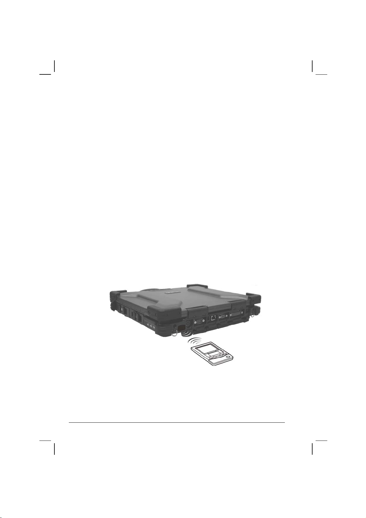
Connecting an IR Device
Your computer has an IR (infrared) port for connecting an
infrared-equipped device wirelessly such as another computer, printer, or
PDA (Personal Digital Assistant).
Follow this procedure to connect an IR device:
1. Make sure that the “Serial Port COM2 (FIR)” item is set properly in
the SCU prog
information.)
2. When using the IR port of your computer to receive data:
Place the tran
your computer within the effective range − within ±20-degrees
vertical angle and within ±20-degrees horizontal angle at no greater
than 0.8~1.0 meter distance.
When using the IR port of your computer to transmit data:
Place the receiving device where the IR port of your computer faces
its IR port within the effective range − within ±15-degrees vertical
angle and within ±15-degrees horizontal angle at no greater than
0.8~1.0 meter distance.
ram. (See “Advanced Menu” in Chapter 5 for
smitting device where its IR port faces the IR port of
To take advantage of the IR communications, you need a third party
software.
4-6 Expanding Your Computer
Page 82

NOTE: During infrared communication, take note of the following:
Do not move the computer and IR device.
Do not enter Standby mode.
Do not use a cell phone or another IR device near the computer.
Avoid strong light such as sunlight or fluorescent light.
Disable the screen saver.
Expanding Your Computer 4-7
Page 83

Connecting an IEEE 1394B Device
NOTE:
Your IEEE 1394B port will only function under Windows XP SP2. It is also Windows
Vista ready.
Make sure that the 1394B driver is installed correctly (see chapter 6 for details).
To connect an IEEE 1394A (also known as FireWire 400) device to the computer’s
IEEE 1394B (also known as FireWire 800) port, you need an optional FireWire
800/FireWire 400 bilingual cable.
Your computer has an IEEE 1394B port for connecting IEEE 1394B
devices.
IEEE 1394B is the next-generation serial bus standard, featuring
high-speed data transfer that doubles the throughput
of the original IEEE
1394A interface (from 400 Mbit/sec to 800 Mbit/sec) and dramatically
increases the maximum distance of connections (up to 15 feet away,
while a FireWire 800 optical repeater will connect devices up to 1000
meters (3300 feet) away). It allows connection of up to 63 devices. The
applications include mass storage device, digital video (DV) camcorder,
or a digital audio device.
To connect an IEEE 1394B device, prepare an IEEE 1394B cable. Plug
the appropriate end of the cable to the com
puter’s IEEE 1394B connector
and the other end to the device’s corresponding connector.
4-8 Expanding Your Computer
Page 84

Using PC Cards
Your computer has a PC card slot.
PC cards are credit card-sized peripheral products based on the standards
developed b
Association). PCMCIA is a non-profit association for promoting the
interchangeability among mobile computers where ruggedness, low
power, and small size are critical.
PC Card Type
Your computer’s PC card slot can accommodate two type II card or one
type II card and one smart card (option). Typical type II cards are flash
memory, SRAM, modem, LAN, and SCSI cards.
y PCMCIA (Personal Computer Memory Card International
CardBus Support
Your computer’s PC card slot supports CardBus specifications. CardBus
is the 32-bit version of PC card technology. It allows speeds of up to 133
Mbps at 33 MHz. Typical applications are SCSI host bus and high-speed
network cards.
Inserting and Removing a PC Card
NOTE:
Some PC cards require additional system resources. Before using such PC card,
you may have to free other system resources for the PC card.
Although some PC cards can be inserted and removed without turning off the
computer, you cannot remove or install PC cards during Standby mode.
To insert a PC card:
1. Locate the PC card slot on the right side of the computer.
Expanding Your Computer 4-9
Page 85

2. Open the PC card slot cover by pressing on both sides of the release
latch using your thumb and index fingers.
3. Slide the PC card, with its label facing up, into t
he slot until the eject
button pops out.
Eject Button
4. When a new card is seated, the computer will detect it and try to
install the appropriate driver. Follow the on-screen instructions to
complete the process.
To remove a PC card:
1. Double-click on the Safely Remove
Hardware
icon found on the
Windows XP taskbar and the Safely Remove Hardware window
appears on screen.
2. Select (highlight) the PC card from the list to disable the card.
3. Push the eject button and the card will slide out slightly.
4. Pull the card out of the slot.
4-10 Expanding Your Computer
Page 86

System Memory Upgrade
You can upgrade your computer by changing system memory to a
maximum of 2 GB on the two 200-pin 400/533 MHz DDR2 SO-DIMM
slots.
To install the SO-DIMM:
1. Carefully place the notebook computer upside down.
2. Remove the nine screws to detach the SO-DIMM compartment
cover.
Expanding Your Computer 4-11
Page 87

3. To install the SO-DIMM, match the SO-DIMM's notched part with
the socket's projected part and firmly insert the SO-DIMM into the
socket at a 20-degree angle. Then push down until the retaining clips
lock the SO-DIMM into position.
4. Replace the SO-DIMM compartment cover and secure with nine
ws.
scre
4-12 Expanding Your Computer
Page 88

CHAPTER
5
Setup Configuration Utility (SCU)
SCU is a program for configuring the BIOS (Basic Input/Output System)
settings of the computer.
BIOS is a layer of software, called firmware, that translates instructions
from
other layers of software into instructions that the computer hardware
can understand. The BIOS settings are needed by your computer to
identify the types of installed devices and establish special features.
This chapter tells you how to use the SCU program.
Page 89

When and How to Use the SCU Program
When to Use
You need to run the SCU program when:
You see an error message on the screen requesting you to run Setup.
You want to restore the factory default settings.
You want to modify some specific settings according to the
hardware.
You want to modify some specific settings to optimize system
performance.
Starting SCU
NOTE:
The Setup screens shown in this chapter are for your reference only. The actual
items or settings on your computer may differ.
The Setup program may have been updated after the publication of this manual.
The settings you select in your operating system might override similar settings in
Setup.
To run SCU, press F2 when the prompt appears in the lower left corner of
the screen during system startup. The prompt shows up on the screen for
only a few seconds. You must press
F2 quickly. The SCU menu appears
as shown next.
5-2 Setup Configuration Utility (SCU)
Page 90

The SCU menu can be divided into four areas:
On the top is the menu bar containing the titles of the available
menus. Each menu title brings a specific menu.
The center column of the menu displays the current configuration
information of the system, devices, and memory items.
The right column of the menu provides more detailed information
when a menu item is highlighted.
On the bottom keyboard keys are displayed for navigating the screen.
Setup Configuration Utility (SCU) 5-3
Page 91

Moving Around and Making Selections
In most cases, you must go through two levels to complete the setting for
an item: menu title and submenu.
Use the keyboard to move around and make selections. A brief
description of
Key Function
keyboard usage is listed next:
← , →
↑ , ↓
+, – Changes the value.
Enter
Esc
F1
F9
F10
Selects a menu title.
Selects an item or option.
1) Brings up the sub-menu when available.
) Opens or closes the option window when an item is selected.
2
1) Displays the Exit menu.
) Closes the option window if one is open.
2
Displays help information.
Changes the values to the setup defaults.
Saves and exit the SCU program.
5-4 Setup Configuration Utility (SCU)
Page 92

Main Menu
The Main menu contains the system date and time as well as the IDE
interface setting of the system.
System Time sets the sy
System Date sets the sy
IDE Channel 0/1 Master sets the ty
options are User, Auto, CD-ROM, ATAPI Removable, None, IDE
Removable, and Other ATAPI.
stem time.
stem date.
pe of storage device installed. The
Setup Configuration Utility (SCU) 5-5
Page 93

Advanced Menu
The Advanced menu contains the I/O (input/output) configuration
settings of the system.
Serial Port COM1 enables or disables the serial (C
OM1) port. The
options are Enabled and Disabled.
Serial Port COM2 (FIR) enables or disables the infr
ared (COM2) port.
The options are Enabled and Disabled.
Serial Port COM3 (Touchscreen) en
ables or disables the touchscreen
(COM3) function. The options are Enabled and Disabled.
Serial Port COM4 (XBay) enables or disables the XBay
(COM4) port.
The options are Enabled and Disabled.
Parallel Port enables or disables the pa
rallel port. The options are
Enabled and Disabled.
HDD Heater sets if the system
automatically turns on the built-in hard
disk drive heater for low temperature operation. The options are Enabled
and Disabled.
NOTE:
To use the HDD heater feature, the MTCCTRL driver supplied with your computer
must be installed (see chapter 6 for details).
Disable this item to conserve energy when using battery power.
5-6 Setup Configuration Utility (SCU)
Page 94

Falling Time to Park HDD sets the time (millisecond) for EC to inform
SMI to park the HDD during an accidental drop. The options are 0
(disabled) to 127.
Free Drop Status specifies if the computer had been free-dropped. The
options are Yes and No.
CPU Thermal Control Sub-Menu set
s the items that control various
CPU thermal parameters.
Summary Screen sets if the sy
stem configuration would be displayed
onscreen during system boot-up. The options are Enabled and Disabled.
Boot-time Diagnostic Screen sets if the sy
stem diagnostic screen would
be displayed during system boot-up. The options are Enabled and
Disabled.
SATA – Device 31, Function 2 sets the primary
/secondary
compatible/enhanced SATA/PATA (serial ATA / parallel ATA)
controller in Legacy/Native mode. The options are Compatible and
Enhanced.
Setup Configuration Utility (SCU) 5-7
Page 95

Boot Menu
The Boot menu sets the sequence of the devices to be searched for the
operating system.
The bootable devices will be automatically detected during POST and
shown here, allowing
you to set the sequence that the BIOS uses to look
for a boot device from which to load the operating system.
A brief description of keyboard usage is listed next:
Key Function
↑ , ↓
+, – Changes the boot sequence.
1 to 4
f or r Specifies if the device is fixed (f) or removable (r).
X
Shift + 1
5-8 Setup Configuration Utility (SCU)
Selects (highlight) a boot device.
Loads the default boot sequence.
Moves the highlighted boot device from the “Boot priority order”
ist to the “Excluded from boot order” list, and vice versa.
l
Deactivates/activates the highlighted boot device on the “Boot
priority order” list. When a device has been deactivated, an “!”
(exclamation) symbol appears beside the item and system will
bypass it when detecting boot device during POST.
Page 96

Exit Menu
The Exit menu displays ways of exiting the SCU program. After finishing
with your settings, you must save and exit so that the changes can take
effect.
Exit Saving Changes saves the changes you have made and exits BIOS
Setup Utilit
Exit Discarding Changes exits BIOS Setup Utility without saving the
changes y
Load Setup Defaults loads the factory default values for all the item
Discard Changes restores the previous values for all the items.
Save Changes saves the changes you
y.
ou have made.
have made.
s.
Setup Configuration Utility (SCU) 5-9
Page 97

5-10 Setup Configuration Utility (SCU)
Page 98

CHAPTER
6
Installing Software Drivers
To take full advantage of the unique features of your computer, some
operating systems require custom software, known as drivers, to be
installed.
If you purchased the computer with Windows pre-installed, your dealer
m
ay have already installed the drivers. If not, you need to install the
drivers using the driver disc supplied with your computer.
This chapter describes how to install the drivers.
Page 99

How to Use the Driver CD
NOTE:
• The drivers may have been updated after this manual was published. For driver
upgrade, please contact your dealer.
• You can always find README or document files on the driver disc. These files
contain the latest information from the software supplier. Please read the files
together with this chapter.
• This driver disc supports Windows 2000 and Windows XP as well as Red-hat Linux
only. You are recommended to install Windows 2000 Service Pack 4 when using
Windows 2000 and Windows XP Service Pack 2 when using Windows XP.
• The available items may differ according to your computer model and operating
system.
• Please do not remove the driver disc when installing the driver.
An autorun program is provided on the driver disc to help you easily
install the drivers. As you insert the driver disc, the autorun program
automatically starts. If you need to start the program manually, run the
Autorun.exe program from the driver disc.
6-2 Installing Software Drivers
Page 100

The main screen appears as shown next:
To install the necessary driver, just click on the particular option and
follow the onscreen instructions to continue and com
plete installation.
Drivers on the First Page
Device Driver Ensures the full function of the following drivers.
Install this main driver before installing the other
drivers. Upon clicking this button, the chipset, VGA,
audio, modem, and LAN drivers would be installed
one after the other.
M54 Utility Installs the optional ATi M54-CSP VGA controller
.
utility
NOTE: You need to install the M54 utility if your system comes with the ATi M54-CSP
Installing Software Drivers 6-3
VGA controller and if you are using Windows XP Service Pack 2 only.
PROSet Installs the WLAN driver that allows your system to
connect wirelessly to the Internet.
 Loading...