

Page 1

A790
Operation Manual
Part Number: 7990 0114 3001 R00
(July 2006)
Page 2

TRADEMARKS
All brand and product names are trademarks or registered trademarks of their
respective companies.
NOTE
Information in this manual is subject to change without notice.
Page 3

Table of Contents
Preface......................................................................................vii
Chapter 1 Getting Started......................................................1-1
Getting the Computer Running..............................................1-2
Unpacking.......................................................................1-2
Connecting to AC Power.................................................1-2
Opening the Cover ..........................................................1-4
Turning On and Off the Computer ..................................1-5
Taking a Look at the Computer.............................................1-6
Right-Side Components...................................................1-6
Left-Side Components.....................................................1-7
Rear Components............................................................1-8
Front Components.........................................................1-10
Top-open Components..................................................1-11
Where to Go from Here.......................................................1-13
Chapter 2 Operating Your Computer....................................2-1
Starting and Stopping the Computer .....................................2-2
Starting the Computer......................................................2-2
Stopping the Computer....................................................2-2
Using the Keyboard...............................................................2-4
Typewriter Keys ..............................................................2-4
Cursor-Control Keys .......................................................2-5
Numeric Keypad..............................................................2-5
i
Page 4

Euro Symbol...................................................................2-6
Windows Keys ................................................................2-6
Function Keys .................................................................2-6
Fn Key.............................................................................2-7
Hot Keys..........................................................................2-7
Using the Touchpad..............................................................2-9
Configuring the Touchpad.............................................2-11
Using the Touchscreen (Optional).......................................2-12
Using the Hard Disk Drive..................................................2-14
Replacing the Hard Disk Drive.......................................2-14
Using the Video Features ....................................................2-17
Configuring the Display Modes .....................................2-17
Using the Audio Features....................................................2-19
Connecting Audio Devices ............................................2-20
Using the Communication Features.....................................2-21
Using the LAN...............................................................2-21
Using the Wireless LAN (Optional)................................2-22
Using the Modem...........................................................2-25
Using the Wireless Modem (Optional) ...........................2-26
Using the GPS (Optional) ..............................................2-27
Using the Bluetooth Feature (Optional)..........................2-28
Chapter 3 Managing Power...................................................3-1
AC Adapter...........................................................................3-2
Battery Pack..........................................................................3-3
Charging the Battery Pack................................................3-3
Initializing the Battery Pack..............................................3-4
Checking the Battery Level..............................................3-5
Replacing the Primary Battery Pack .................................3-5
Battery Low Signals and Actions .....................................3-7
Power Management...............................................................3-8
Hibernation......................................................................3-9
Power-Saving Tips .............................................................3-10
ii
Page 5

Chapter 4 Expanding Your Computer ..................................4-1
Connecting an External Monitor............................................4-2
Connecting a Parallel Device.................................................4-3
Connecting a Serial Device ...................................................4-4
Connecting an IR Device ......................................................4-5
Connecting a USB Device.....................................................4-7
Connecting an IEEE 1394b Device........................................4-8
Using PC Cards.....................................................................4-9
PC Card Type..................................................................4-9
CardBus Support.............................................................4-9
Inserting and Removing a PC Card..................................4-9
System Memory Upgrade....................................................4-11
Chapter 5 Setup Configuration Utility (SCU)........................5-1
When and How to Use the SCU Program..............................5-2
When to Use....................................................................5-2
Starting SCU....................................................................5-2
Moving Around and Making Selections...........................5-4
Main Menu............................................................................5-5
Advanced Menu....................................................................5-6
Intel Menu ............................................................................5-7
Security Menu.......................................................................5-8
Boot Menu............................................................................5-9
Exit Menu ...........................................................................5-10
Chapter 6 Installing Software Drivers..................................6-1
How to Use the Driver CD ....................................................6-2
Touchscreen Driver.........................................................6-6
Chapter 7 Caring for the Computer ......................................7-1
Protecting the Computer .......................................................7-2
Using the Cable Lock.......................................................7-2
Using an Anti-Virus Strategy ...........................................7-2
Taking Care of the Computer................................................7-3
iii
Page 6

Location Guidelines.........................................................7-3
General Guidelines ..........................................................7-3
Cleaning Guidelines.........................................................7-4
Battery Pack Guidelines...................................................7-4
When Traveling....................................................................7-5
Chapter 8 Troubleshooting ...................................................8-1
Preliminary Checklist............................................................8-2
Solving Common Problems..................................................8-3
Battery Problems .............................................................8-4
Bluetooth Problems.........................................................8-4
Display Problems.............................................................8-5
Hardware Device Problems..............................................8-6
Hard Disk Drive Problems...............................................8-6
Infrared Problems............................................................8-7
Keyboard, Mouse and Touchpad Problems .....................8-7
LAN Problems.................................................................8-8
WLAN Problems.............................................................8-8
Modem Problems ..........................................................8-10
PC Card Problems.........................................................8-10
Power Management Problems........................................8-11
Printer Problems............................................................8-11
Software Problems........................................................8-12
Sound Problems............................................................8-12
Startup Problems...........................................................8-13
Other Problems .............................................................8-13
Resetting the Computer.......................................................8-14
Appendix A Specifications.....................................................A-1
Appendix B Regulatory Information......................................B-1
On the Use of the System.....................................................B-2
Class B Regulations........................................................B-2
Safety Notices................................................................. B-3
On the Use of RF Device ..................................................... B-6
iv
Page 7

USA and Canada Safety Requirements and Notices........B-6
European Union CE Marking and Compliance Notices...B-9
v
Page 8

Page 9

Preface
This manual contains information that will help you operate the
computer. It is divided into 8 chapters and 2 appendices.
l Chapter 1, Getting Started, takes you through the process of setting
up the computer and identifying its external components.
l Chapter 2, Operating Your Computer, tells you how to use the
computer’s components and features.
l Chapter 3, Managing Power, provides information on power.
l Chapter 4, Expanding Your Computer, provides information on
installing and using peripheral devices.
l Chapter 5, SCU (Setup Configuration Utility), describes the SCU
program that configures the computer’s BIOS settings.
l Chapter 6, Installing Software Drivers, describes how to install the
drivers and utilities supplied with the computer.
l Chapter 7, Caring for the Computer, gives you tips in care and
maintenance.
l Chapter 8, Troubleshooting, gives solutions to common problems
you may encounter when using the computer.
l Appendix A, Specifications, gives a brief specification of the
computer.
vii
Page 10

l Appendix B, Regulatory Information, provides regulatory
statements and safety notices on your computer.
Notational Conventions
Throughout this manual, the following conventions are used to
distinguish elements of text.
NOTE: identifies additional information that requires special attention.
CAUTION: identifies important information which, if not followed, may result in loss
of data or damage to the computer.
Keyboard keys are shown in a bold typeset. For example:
Press Enter to complete.
When keys are joined by a plus sign (+), press the first key, and, while
keeping the first key down, press the remaining keys, finally release all the
keys. When necessary, keys are also shown in graphics.
A title, command, setup item, or button that you can see on the screen is
shown in boldface. A value or an option that you can select for a setup
item is shown in italic. For example:
Select Power Management, set it to Enabled, and then click the
OK button.
viii
Page 11

CHAPTER
Getting Started
Congratulations on purchasing this computer.
This high performance notebook computer is especially designed for the
practical applications of warehouses, automobiles, vehicles, public
security, repairing, assisting the handicapped, and other demanding
situations where conventional notebook computers just cannot measure
up.
This chapter first tells you step by step how to get the computer up and
running. You will find instructions for these procedures:
l Unpacking
l Connecting to AC power
1
l Opening the cover
l Turning on the computer
l Turning off the computer
Then, you will find a section briefly introducing the external components
of the computer. And the last section navigates you to the information
you may need after the computer is ready for use.
Page 12

Getting the Computer Running
This section guides you through the procedures for getting the computer
ready for operation.
Unpacking
After unpacking the shipping carton, you should find these standard
items:
l Notebook computer
l Accessories:
− AC adapter (100~240 VAC, 50/60 Hz)
− AC power cord (US/CE/UK/SA)
− Driver CD
− This Operation Manual
Inspect all the items. If any item is damaged or missing, notify your
dealer immediately.
Keep the shipping carton and packing materials in case you need to ship
or store the computer in the future.
Connecting to AC Power
The computer operates either on the external AC power or internal
battery power. It is suggested that you use AC power when you start up
the computer for the first time.
CAUTION: Use only the AC adapter included with your computer. Using other AC
adapters may damage the computer.
1-2 Getting Started
Page 13
NOTE:
Power Supply Cord: (optional) Detachable, minimum 1.5 m long. Listed, rated
minimum 125 V, 7 A, having a 2/18 AWG, type SVT flexible cord. One end terminates
with a parallel blade, molded-on, attachments plug with a 7 A, 125 V (NEMA 1-15P)
configuration; other end terminates with a molded-on appliance coupler.
Alternative: (optional) Detachable, maximum 4.5 m (14.76 ft) long. Listed, rated
minimum 250 V, 6 A, having a 3/18 AWG, type SVT flexible cord. One end terminates
with a Tandem blade, grounding, listed molded-on, attachments plug with a 6 A, 250 V
(NEMA 6-15P) configuration; other end terminates with a molded-on appliance
coupler.
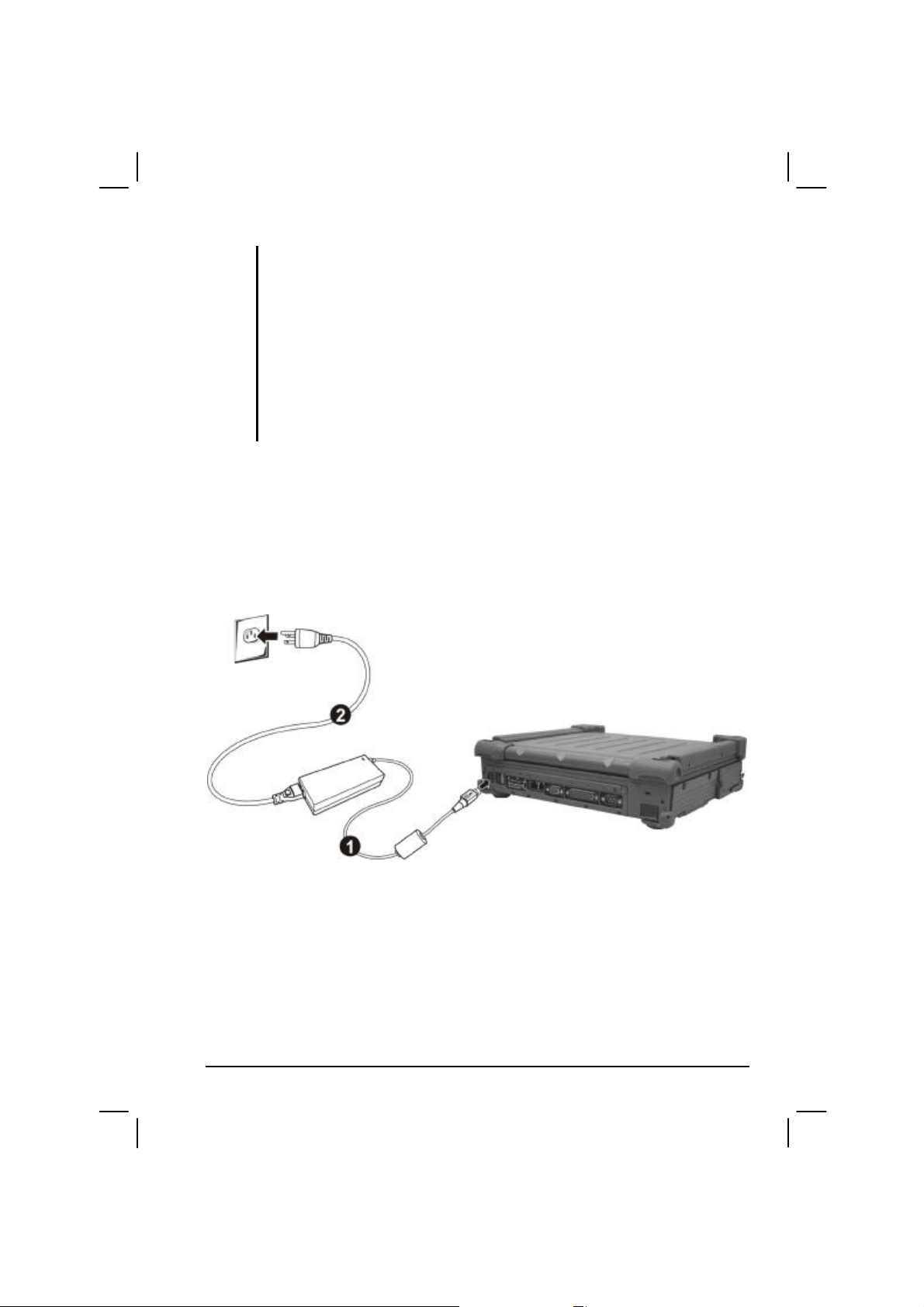
1. Make sure the computer is turned off.
2. Plug the DC cord of the AC adapter to the power connector on the
rear side of the computer (Œ) .
3. Plug the female end of the AC power cord to the AC adapter and the
male end to an electrical outlet (•) .
4. When the AC adapter is connected, the indicator on the AC adapter
lights up, indicating that power is being supplied from the electrical
outlet to the AC adapter and onto your computer. Now, you are ready
to turn on the computer.
Getting Started 1-3
Page 14
CAUTION:
l When you disconnect the AC adapter, disconnect from the electrical outlet first and
then from the computer. A reverse procedure may damage the AC adapter or the
computer.
l When unplugging the connector, always hold the plug head. Never pull on the cord.
NOTE: When the AC adapter is connected, it also charges the battery pack. For
information on using battery power, see Chapter 3.
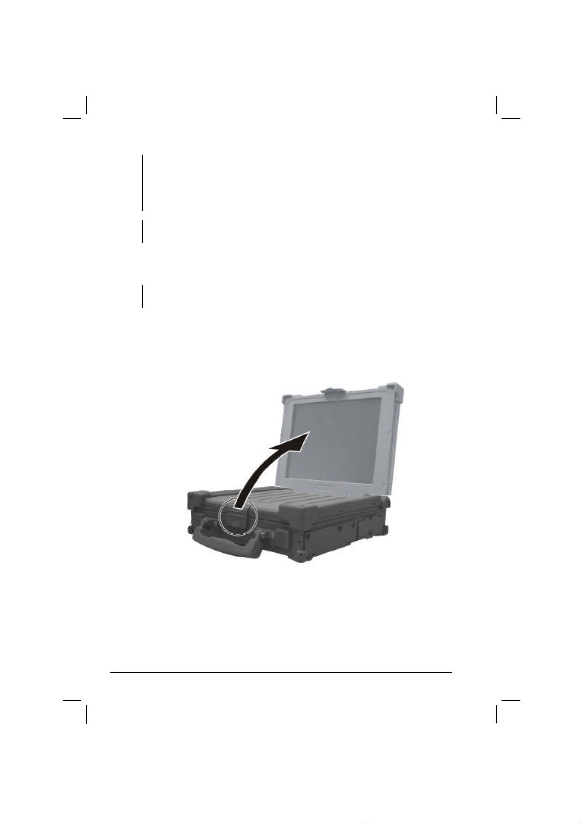
Opening the Cover
CAUTION: Be gentle when opening and closing the cover. Opening it vigorously or
slamming it shut could damage the computer.
1. Open the top cover by pulling on the cover latch.
2. Lift up the cover. You can tilt the cover forward or backward for
optimal viewing clarity.
1-4 Getting Started
Page 15

Turning On and Off the Computer
Turning On
1. Make sure the computer is connected to AC power.
2. Press the power button.
3. Each time the computer is turned on, it performs a Power-On Self
Test (POST), and the operating system such as Windows should
start.
Turning Off
To turn off the computer power, use the “Shut Down” command of your
operating system.
NOTE: There are other ways you can stop the computer so that you will be back to
where you left off when you next turn on the computer. (See “Stopping the Computer”
Getting Started 1-5
in Chapter 2 for information.)
CAUTION: If you have to turn the computer on again immediately after turning it off,
wait for at least five seconds. Turning the computer off and on rapidly can damage it.
Page 16

Taking a Look at the Computer
This section identifies the external components of the computer and
briefly describes the function of each component.
NOTE: Depending on the model you purchased, the appearance of your computer m ay
not exactly be the same as those shown in this manual.
Right-Side Components
Ref Component Description See Also
PC Card Slot Accepts a PC card for additional functions. P. 4-9
Œ
??? ???
•
Audio Output
Ž
Connector
Microphone
•
Connector
IEEE 1394B
•
Port
Hard Disk
‘
Drive
Compartment
1-6 Getting Started
Connects a set of headphones, external speakers
with amplifier, or an audio recording device.
Connects an external microphone. P. 2-20
Connects a 1394B device such as a mass storage
device, digital video (DV) camcorder, or a digital
audio device.
Contains the hard disk drive of your computer. P. 2-14
P. 2-20
P. 4-8
Page 17

Left-Side Components
Ref Component Description See Also
Bay2 Slot May contain an extra battery pack or wireless
Œ
Battery Pack Supplies power to your computer when external
•
modem (GPRS/GSM, CDMA) module.
power is not connected.
P. 3-3
Getting Started 1-7
Page 18
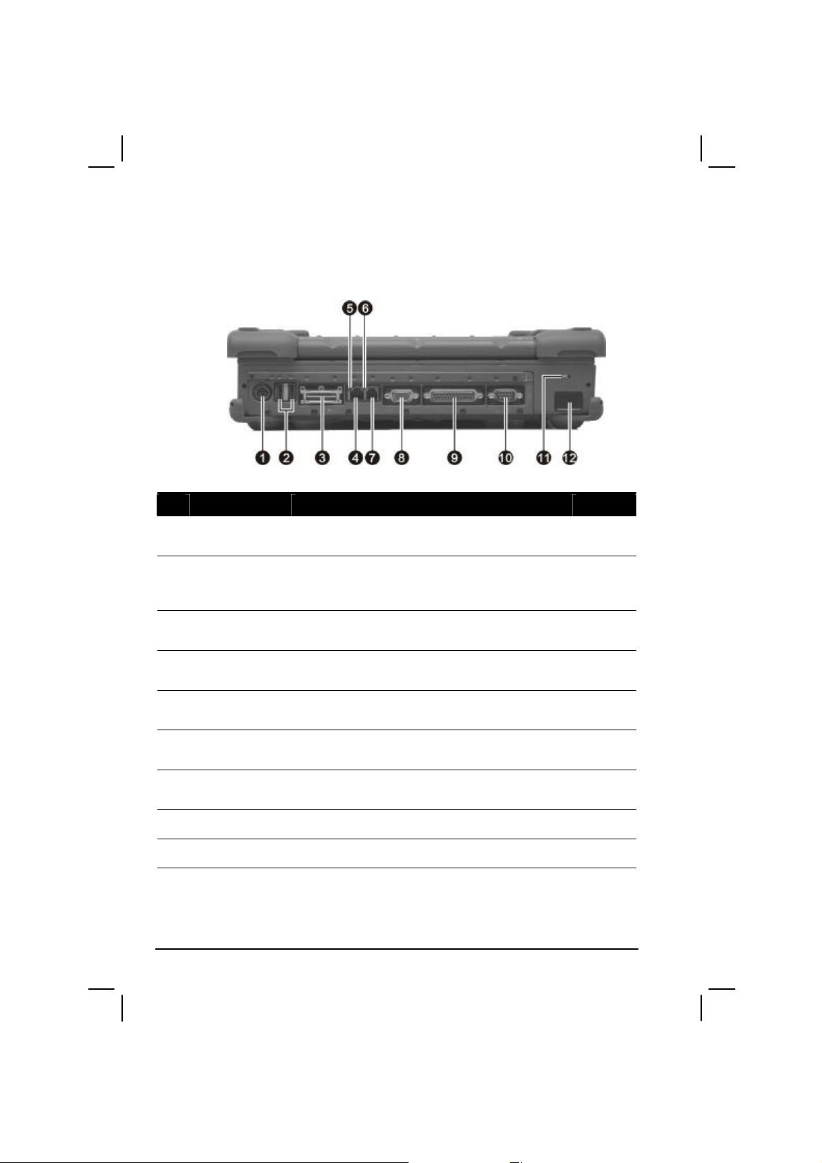
Rear Components
Ref Component Description See Also
Power
Œ
Connector
USB Ports Each of the two ports connects a USB device,
•
Docking Port For connecting to a Port Replicator / car mount
Ž
RJ-45
•
Connector
Active Indicator Blinks green when the system is accessing the
•
Link Indicator Glows green when the system has an available
‘
RJ-11
’
Connector
VGA Port Connects an external CRT monitor. P. 4-2
“
Parallel Port Connects a parallel device, such as a printer. P. 4-3
”
Connects the AC adapter. P. 1-3
P. 4-7
such as a USB floppy drive, USB flash disk,
printer, digital camera, joystick, and more.
(both are available as an option).
Connects the LAN cable. Includes a Link
Indicator and an Active Indicator.
LAN.
connection to LAN.
Connects the telephone line. P. 2-25
P. 2-21
P. 2-21
P. 2-21
1-8 Getting Started
Page 19

Ref Component Description See Also
Serial Port Connects a serial device, such as an external
•
Kensington
Lock
modem.
Locks the computer to a stationary object for
security.
P. 4-4
P. 7-2
IR Port Connects an IrDA-compliant device for wireless
data transfer.
P. 4-5
Getting Started 1-9
Page 20
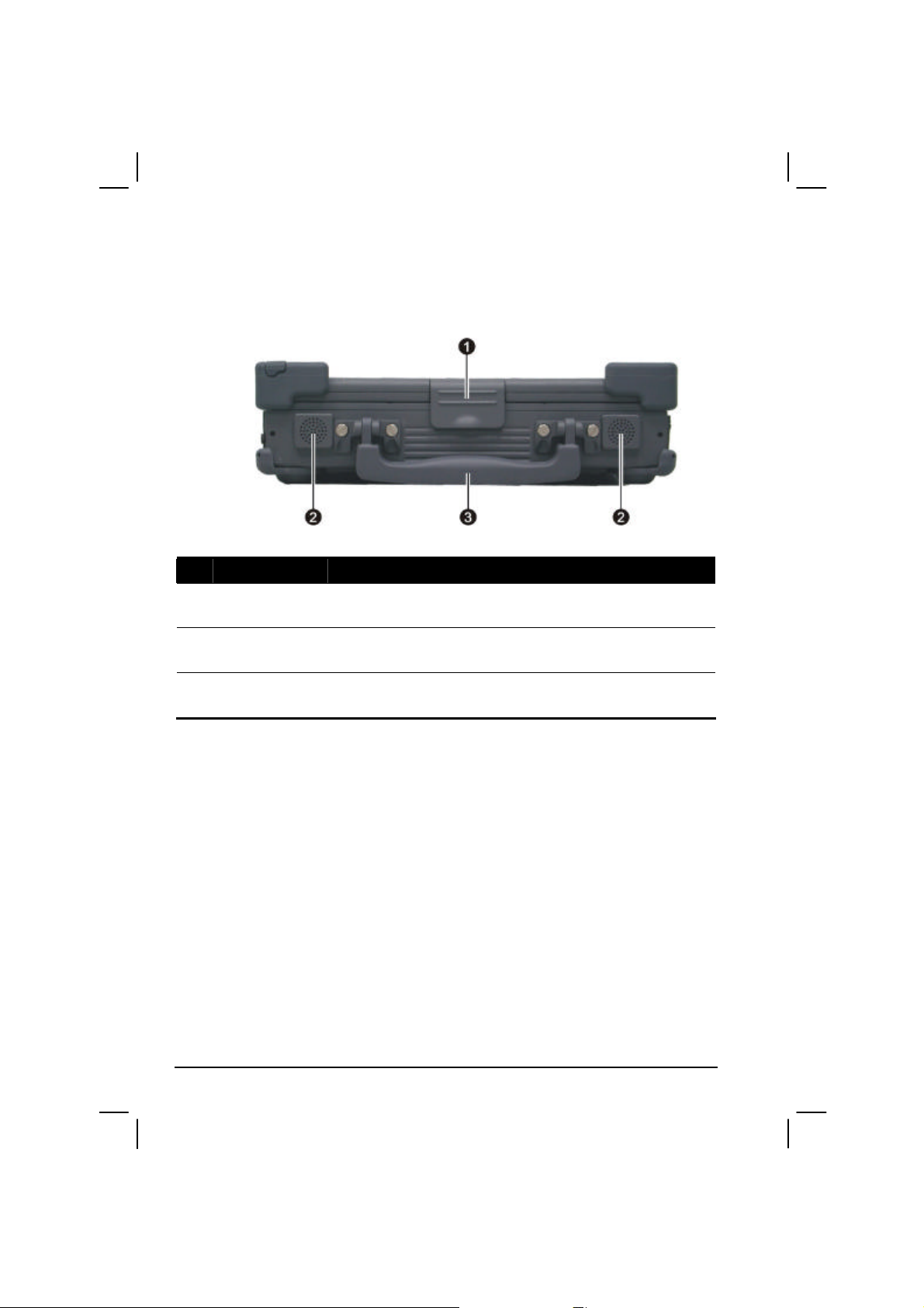
Front Components
Ref Component Description See Also
Top Cover
Œ
Latch
Stereo Speaker
•
Set
Handle Allows you to carry your computer for an easy
Ž
Locks the top cover. P. 1-4
Sends out sound and voice from the computer. P. 2-19
grip.
1-10 Getting Started
Page 21
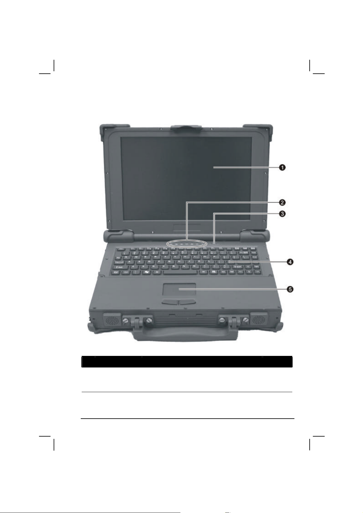
Top-open Components
Ref Component Description See Also
LCD Screen Displays the output of the computer.
Œ
Getting Started 1-11
Can also have the optional touchscreen
function.
P. 2-17
P. 2-12
Page 22

A
N
Ref Component Description See Also
•
Device
Indicators
Show the current status of the computer’s
devices.
Scroll Lock indicator P. 2-4
Caps Lock indicator P. 2-4
Num Lock indicator P. 2-6
Hard disk drive in-use indicator P. 2-14
Battery charge indicator –
Glows green when the battery is fully charged
and connected to AC power.
Glows amber (orange) when the battery is being
charged.
Battery power indicator –
Glows green when the computer is using battery
power.
Glows amber (orange) when the optional
Bay1/Bay2 battery pack’s capacity is under
5 %.
Blinks amber (orange) when the primary battery
packs capacity is under 5 % even when the other
battery pack is fully charged.
Power on / Standby mode indicator –
Glows green when the computer is turned ON.
Glows orange when the computer is in Standby
mode.
P. 3-3
P. 3-3
P. 1-5
Power Button Turns the computer power ON and OFF. P. 1-5
Ž
Keyboard Serves as the data input device of the computer.
•
Touchpad Serves as the pointing device of the computer. P. 2-9
•
1-12 Getting Started
P. 2-4
Page 23

Where to Go from Here
As your computer is ready for operation, you may want to do any of the
following now:
For this purpose… Do this…
To know more about the computer… Go on to the next chapter.
To install the operating system if your
dealer has not already done so…
To know more about the operating
system…
To install the drivers if your dealer has
not already done so…
To charge the battery pack for the first
time…
See the operating system manual.
Read the operating system manual.
See Chapter 6.
See “Charging the Battery Pack” in
Chapter 3.
Getting Started 1-13
Page 24

1-14 Getting Started
Page 25

CHAPTER
Operating Your Computer
This chapter provides information about the use of the computer.
If you are new to computers, reading this chapter will help you learn the
operating basics. If you are already a computer user but are new to
notebook computers, you may choose to read only the parts containing
information unique to your computer.
Described in this chapter are the operating basics of these components:
l Keyboard
l Touchpad
l Touchscreen
2
l Hard disk drive
And these features:
l Starting and stopping the computer
l Video features
l Audio features
l Communication features
Page 26

Starting and Stopping the Computer
There are a number of ways to start and stop the computer.
Starting the Computer
You always start the computer using the power button.
A computer starts up with an operating system (OS) existing on the
storage device such as the hard disk; or from a CD disc if you have the
respective modules installed. The computer will automatically load the
OS after you turn it on. This process is called booting.
NOTE: An operating system is the platform for all your software application programs to
run on. The most widely used operating system today is Microsoft Windows.
Stopping the Computer
When you finish a working session, you can stop the computer by turning
off the power or leaving the computer in Standby or Hibernation mode:
To stop in
this mode…
Off Follow the shutdown procedure of your
operating system. This can prevent loss of
unsaved data or damage to your software
programs.
If the system is locked up because of
hardware or software problems, press the
power button to turn off the computer.
Standby Depending on your settings in Windows,
you can place the computer in Standby
mode by:
• Closing the display cover
• Pressing Fn+F12
• Pressing the power button
Do this… To start up or
resume again
Press the power
button.
Press any key.
2-2 Operating Your Computer
Page 27

To stop in
this mode…
Hibernation Depending on your settings in Windows,
you can place the computer in
Do this… To start up or
resume again
Press the power
button.
Hibernation mode by:
• Closing the display cover.
• Pressing Fn+F12
• Pressing the power button
If you choose to stop in Standby or Hibernation mode, you can return to
where you left off the next time you start up the computer. (See “Power
Management” in Chapter 3 for more information.)
Operating Your Computer 2-3
Page 28

Using the Keyboard
NOTE: Your computer features backlight for your keyboard to help you see the
keyboard keys during poor lighting conditions. Press Fn+F8 to turn it on/off (see Hot
Keys later in this chapter).
Your special shower-proof and dust-proof rubber keyboard has all the
standard functions of a full-sized computer keyboard plus an Fn key
added for specific functions.
The standard functions of the keyboard can be further divided into four
major categories:
l Typewriter keys
l Cursor-control keys
l Numeric keys
l Function keys
Typewriter Keys
Typewriter keys are similar to the keys on a typewriter. Several keys are
added such as the Ctrl, Alt, Esc, and lock keys for special purposes. When
the lock keys (Caps Lock, Num Lock, and Scroll Lock) are pressed, their
corresponding indicators light up.
The Control key is normally used in combination with other keys for
program-specific functions. The Alternate key is normally used in
combination with other keys for program-specific functions. The Escape
key is usually used for stopping a process. Examples are exiting a
program and canceling a command. The function depends on the program
you are using.
2-4 Operating Your Computer
Page 29
Cursor-Control Keys
NOTE: The word “cursor” refers to the indicator on the screen that lets you know
exactly where on your screen anything you type will appear. It can take the form of a
vertical or horizontal line, a block, or one of many other shapes.
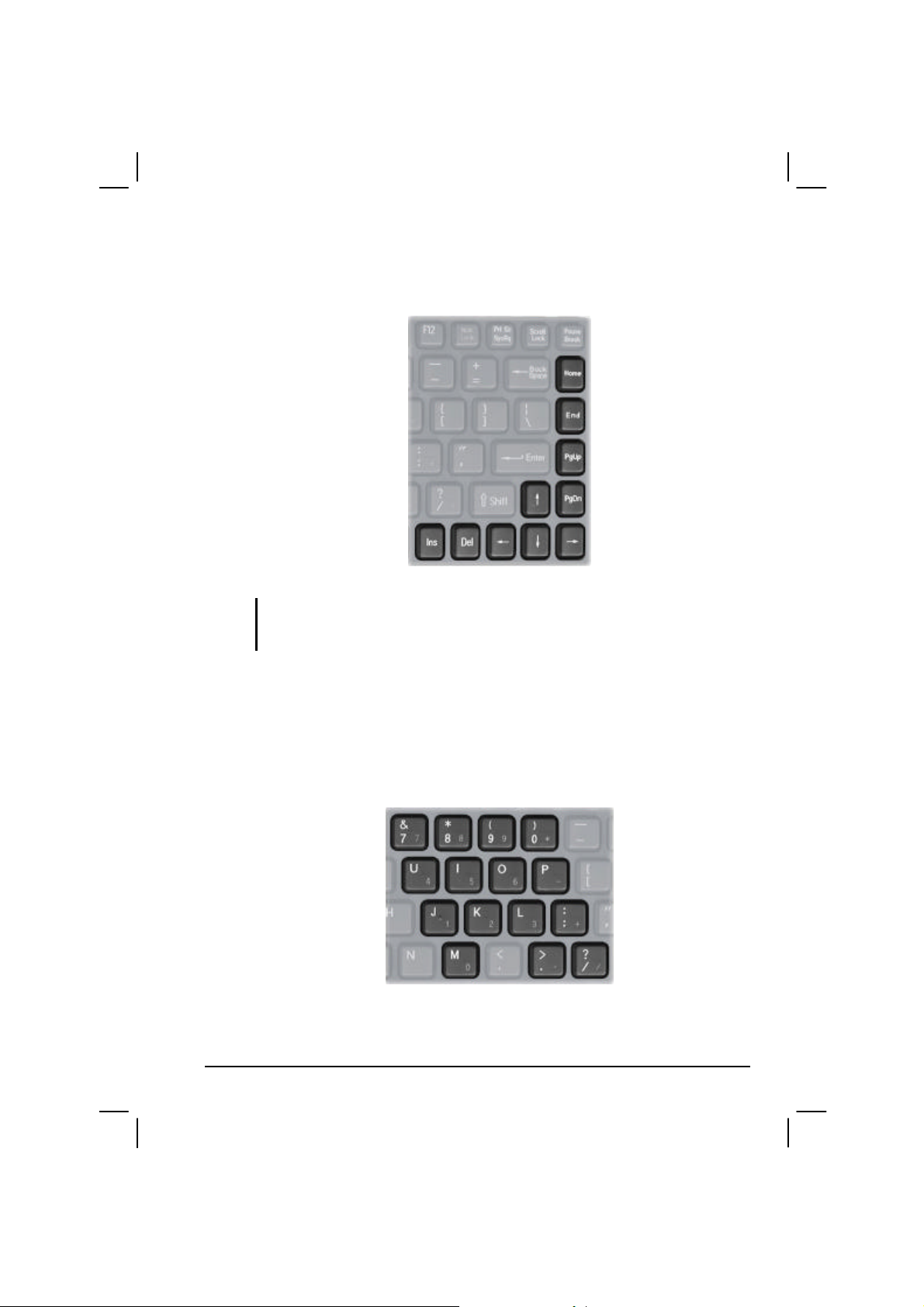
Numeric Keypad
A 15-key numeric keypad is embedded in the typewriter keys as shown
next:
Operating Your Computer 2-5
Page 30

Numeric keys facilitate entering of numbers and calculations. When Num
Lock is on, the numeric keys are activated; meaning you can use these
keys to enter numerals.
NOTE:
l When the numeric keypad is activated and you need to type the English letter in the
keypad area, you can turn Num Lock off or you can press Fn and then the letter
without turning Num Lock off.
l Some software may not be able to use the numeric keypad on the computer. If so,
use the numeric keypad on an external keyboard instead.
Euro Symbol
You can press the Euro dollar sign on the keyboard.
l To press the Euro sign on the keyboard, hold down either of the Alt
keys and type 0128 on the numeric keypad of your keyboard.
l To press the Euro sign on an UK keyboard, hold down the Alt Gr key
and press 4 (which has an Euro sign on it).
Windows Keys
The keyboard has two keys that perform Windows-specific functions:
Windows Logo key and Application key.
The Windows Logo key opens the Start menu and performs
software-specific functions when used in combination with other keys.
The Application key usually has the same effect as a right mouse
click. (See your Windows manual for more information.)
Function Keys
On the top row of the keys are the function keys: F1 to F12. Function keys
are multi-purpose keys that perform functions defined by individual
programs.
2-6 Operating Your Computer
Page 31

Fn Key
The Fn key, at the lower left corner of the keyboard, is used with another
key to perform the alternative function of a key. The letter “Fn” and the
alternative functions are identified by the color of blue on the keytop. To
perform a desired function, first press and hold Fn, then press the other
key.
Hot Keys
Hot keys refer to a combination of keys that can be pressed any time to
activate special functions of the computer. Most hot keys operate in a
cyclic way. Each time a hot key combination is pressed, it shifts the
corresponding function to the other or next choice.
You can easily identify the hot keys with the icons imprinted on the
keytop. The hot keys are described next.
Key Description
Decreases the sound volume.
Increases the sound volume.
Decreases the LCD brightness.
Increases the LCD brightness.
Switches the GPS function on and off.
NOTE: This function works only if an optional Bay2 module
with GPS function is installed.
Switches the optional keyboard backlight function on/off with
10 levels of brightness in-between.
Operating Your Computer 2-7
Page 32

Key Description
Switches the display output to one of the following when an
external device is connected.
Upon booting the system with CRT:
LCD LCD & CRT
CRT
Upon booting the system with DVI:
LCD LCD & DVI
DVI
NOTE:
l When in full screen DOS mode, or when playing DVD or
MPEG file, display switching is not allowed.
l If the display mode is set to 256 colors or lower, or in DOS
mode, there will be only two modes for selecting: CRT only
and LCD & CRT.
l This function only applies to Plug & Play CRT monitors.
Switches the display off and on.
Switches the LCD backlight on and off.
Serves as the sleep button that you can define with Windows’
Power Management. (See the “Power Management” in
Chapter 3.)
2-8 Operating Your Computer
Page 33

Using the Touchpad
CAUTION: Do not use a sharp object such as a pen on the touchpad. Doing so may
damage the touchpad surface.
NOTE: For optimal performance of the touchpad, keep your fingers and the pads clean
and dry. When tapping on the pad, tap lightly. Do not use excessive force.
The touchpad is a pointing device that allows you to communicate with
the computer by controlling the location of the pointer on the screen and
making selection with the buttons.
The touchpad consists of a rectangular pad and two buttons. To use the
touchpad, place your forefinger or thumb on the pad. The rectangular pad
acts like a miniature duplicate of your display. As you slide your fingertip
across the pad, the pointer (also called cursor) on the screen moves
accordingly. When your finger reaches the edge of the pad, simply
relocate yourself by lifting the finger and placing it on the other side of
the pad.
Here are some common terms that you should know when using the
touchpad:
Operating Your Computer 2-9
Page 34

Term Action
Point Move your finger on the pad until the cursor points to the
selection on the screen.
Click Press and release the left button.
–or–
Tap gently anywhere on the pad.
Doubleclick
Drag
and
drop
Scroll To scroll is to move up and down or left and right in the working
Press and release the left button twice in quick succession.
–or–
Tap twice on the pad rapidly.
Press and hold the left button, then move your finger until you
reach your destination (drag). Finally, release the button (drop)
when you finish dragging your selection to the destination. The
object will drop into the new location.
–or–
Gently tap twice on the pad and on the second tap, keep your
finger in contact with the pad. Then, move your finger across the
pad to drag the selected object to your destination. When you lift
your finger from the pad, the selected object will drop into place.
area on the screen.
The scroll button located between the two buttons under the
touchpad can be used to move vertically in a convenient way.
Press the upper part of the scroll button to move up and the lower
part of the scroll button to move down.
–or–
To move vertically, place your finger on the right edge of the
pad and slide your finger up and down along the edge. To move
horizontally, place your finger on the bottom edge of the pad and
slide your finger left and right.
TABLE NOTE: If you swap the left and right buttons, “tapping” on the touchpad
as an alternative method of pressing the left button will no longer be valid.
2-10 Operating Your Computer
Page 35

Configuring the Touchpad
You may want to configure the touchpad to suit your needs. For example,
if you are a left-handed user, you can swap the two buttons so that you
can use the right button as the left button and vise versa. You can also
change the size of the on-screen pointer, the speed of the pointer, and so
on.
To configure the touchpad, you can use the standard Microsoft or IBM
PS/2 driver if you are using Windows to take advantage of more powerful
features.
Operating Your Computer 2-11
Page 36

Using the Touchscreen (Optional)
CAUTION: Do not use a sharp object such as a ballpoint pen or pencil on the
touchscreen. Doing so may damage the touchscreen surface.
The touchscreen is a touch-sensitive device that allows you to
communicate with the computer by controlling the location of the pointer
on the screen and making selection with the buttons.
The touchscreen needs a special device driver support that allows you to
easily use the computer without a mouse or touchpad (see chapter 6 for
details).
Here are some common terms that you should know when using the
touchscreen:
Term Action
Click/Point Tap gently on the touchscreen.
Double-click Tap twice on the touchscreen rapidly.
2-12 Operating Your Computer
Page 37

Term Action
Drag and
drop
Press lightly on the touchscreen and move your finger
until you reach your destination (drag). Finally, release
your finger (drop) when you finish dragging your selection
to the destination. The object will drop into the new
location.
Scroll To scroll is to move up and down or left and right in the
working area on the screen.
To move vertically, place your finger on the right edge of
the touchscreen and slide your finger up and down along
the edge. To move horizontally, place your finger on the
bottom edge of the touchscreen and slide your finger left
and right.
This function works only after you install the touchscreen
driver supplied with the computer and it may not work for
all applications.
Operating Your Computer 2-13
Page 38

Using the Hard Disk Drive
Your computer comes with a hard disk drive as drive C. A hard disk drive
is a storage device with non-removable, rotating, magnetic storage
platters inside it. It is where your operating system and application
software programs are stored.
Your hard disk drive is a 2.5-inch IDE (Integrated Drive Electronics) hard
disk drive that features a built-in G-sensor to prevent damage during an
accidental drop. This type of drive embodies the latest in fast, reliable
mass storage by integrating all the control circuitry necessary for
operation directly onto the drive itself. This allows the drive
manufacturer to carefully optimize drive performance.
The system may come with an optional built-in heater that automatically
turns on for low temperature operation.
CAUTION:
l Make regular backups of your data files from your hard disk drive to CD discs or
other storage media.
l Never try to remove or install the hard disk drive while the computer is powered on.
Doing so can result in loss of data, and can damage the computer and the hard disk
drive’s sensitive circuitry.
l Never turn off or reset the computer while the hard disk drive in-use indicator is on.
Replacing the Hard Disk Drive
To replace the hard disk drive:
1. Make sure that system power is off.
2. Remove the battery pack (see chapter 3 for details).
3. Locate the hard disk drive slot on the right side of the system.
2-14 Operating Your Computer
Page 39

4. Remove the two screws securing the hard disk drive compartment.
5. Lift up the handle and pull on it to remove the hard disk drive
compartment.
6. Remove the two screws securing the hard disk drive to the
compartment and remove the steel plate cover.
Operating Your Computer 2-15
Page 40

7. Lift up the hard disk drive from the compartment and replace it with a
new one.
8. Replace the steel plate cover and replace the two screws to secure the
hard disk drive to the compartment.
9. Replace the hard disk drive compartment to the computer and secure
with two screws.
10. Replace the battery pack.
2-16 Operating Your Computer
Page 41

Using the Video Features
The video subsystem of your computer features:
l 12.1/14.1-inch TFT (Thin-Film Transistor) color LCD display with
1024×768 XGA (eXtended Graphics Array) resolution, or
optional 14.1-inch TFT (Thin-Film Transistor) color LCD display
with 1400×1050 SXGA+ / SXGA (Super eXtended Graphics Array)
resolution
l 64 MB video memory shared with system memory
l LCD backlight to help you see the display during poor lighting
conditions. Press Fn+F11 to turn it on/off (see Hot Keys in this
chapter).
l Simultaneous display on LCD and external monitor, which is useful
when you have a presentation as you can control the screen from your
computer and face the audience at the same time.
l Dual view capability, which allows you to expand your desktop on
the screen to another display device so that you have more desktop
space to work on.
l Power Management.
l Sunlight-readable LCD display (option).
NOTE:
l To take advantage of the enhanced video capabilities and before using the dual
view capability, the device driver supplied with your computer must be installed
(see chapter 6 for details).
l System enters Standby/Hibernation mode when the LCD is closed. If you want to
use the computer with the LCD closed, set Do Nothing to the “When I close the lid
of my portable computer” option in the Power Options Properties. Thus the
computer does not enter Standby or Hibernation mode when the LCD is closed.
Configuring the Display Modes
Your computer has been set to a default resolution and number of colors
before shipment. You can view and change display settings through your
operating system. See your operating system documentation or online
help for specific information.
Operating Your Computer 2-17
Page 42

For displaying in higher resolutions, you can connect an external CRT
monitor that supports higher resolutions. (See “Connecting an External
Monitor” in Chapter 4 for more information.)
The following table lists the display modes supported by your computer.
Display Mode LCD Only CRT Only Simultaneous Display
Resolution Colors
800×600
16-bit
32-bit
1024×768
16-bit
32-bit
√ √ √
√ √ √
√ √ √
√ √ √
TABLE NOTE:
l 16-bit = High Color or 65,536 (64 K) colors; 32-bit = True Color 16,770,000 (16 M)
colors.
l When using CRT only, the resolution would depend on the supported resolution by
the CRT.
2-18 Operating Your Computer
Page 43

Using the Audio Features
NOTE:
l To take advantage of the enhanced audio capabilities, the device driver supplied
with your computer must be installed (see chapter 6 for details).
l If you experience interference while recording, try lowering the microphone
recording volume.
The audio subsystem of your computer features:
l External audio connectors (
l A set of speakers (
•
)
Œ
) and
Ways of playing and recording sound vary with the operating system
used. See your operating system documentation or online help for
specific information.
Operating Your Computer 2-19
Page 44

Connecting Audio Devices
For higher audio quality, you can send or receive sound through external
audio devices.
l Audio Output Connector (
) can be connected to the line-in
connector of powered speakers with built-in amplifiers, headphones,
or earphone set.
l Microphone Connector (
) can be connected to an external
microphone for recording voice or sound.
NOTE: When using external speakers/headphones or microphone, you cannot use the
internal one.
2-20 Operating Your Computer
Page 45

Link
Active
indicator
Using the Communication Features
Using the LAN
NOTE: To take advantage of the LAN feature, the device driver supplied with your
computer must be installed (see chapter 6 for details).
The internal 10/100/1000Base-T Ethernet LAN (Local Area Network)
module allows you to connect your computer to a network. It supports
data transfer rate up to 1000 Mbps.
To connect the network cable to the LAN module, connect one end of the
LAN cable to the RJ-45 connector on the computer and the other end to
the network hub.
Active Indicator Blinks green when the system is accessing the LAN.
Link Indicator Glows green when the system has an available
connection to LAN.
indicator
Operating Your Computer 2-21
Page 46

Using the Wireless LAN (Optional)
Depending on your model, an internal Mini PCI wireless LAN (WLAN)
card may have been pre-installed by your computer manufacturer at the
factory. This card allows you to access corporate networks or the Internet
in a wireless environment.
The WLAN features include:
l Peer-to-Peer (Ad-Hoc) and Access Point (Infrastructure) modes
support
l WEP (Wired Equivalent Privacy) 64/128-bit data encryption
l IEEE 802.11a/b/g standard compliance
Technology 802.11a 802.11b 802.11g
Stated Maximum
Throughput (Mbps)
Data Rates (Mbps) 54, 48, 36, 24, 18,
Band (GHz) 5.15 ~ 5.35 2.412 ~ 2.462 2.4
Modulation
Technology
NOTE: 802.11g mode is backward compatible with 802.11b mode.
To take advantage of the WLAN feature, make sure that the WLAN
driver is installed correctly (see chapter 6 for details). If your WLAN card
was provided by your dealer instead of the computer manufacturer,
contact your dealer for the correct driver to use.
54 11 54
11, 5.5, 2, 1 54, 36, 18, 9
12, 9, 6
OFDM (Orthogonal
Frequency Division
Multiplexing)
DSSS (Direct
Sequence Spread
Spectrum)
OFDM (Orthogonal
Frequency Division
Multiplexing)
2-22 Operating Your Computer
Page 47

Configuring the WLAN
After driver installation, you can use the WLAN utility to configure and
monitor your WLAN connection. If you are using Windows XP, you can
also use its built-in WLAN utility. Follow this procedure to launch the
WLAN utility in Windows XP:
1. Select Control Panel from the Start menu.
2. Click Network and Internet Connections.
3. Click Network Connections, then double-click the Wireless Network
Connection icon .
4. Click Properties in the Wireless Network Connection Status dialog
box.
5. You can configure your WLAN settings in the Wireless Network
Connection Properties dialog box.
Connecting to a Wireless Network
To connect to a wireless network:
1. Make sure that the WLAN radio is on.
2. Click Start and then All Programs.
3. Click Intel PROSet Wireless and then Intel PROSet Wireless.
Operating Your Computer 2-23
Page 48

4. If any wireless network is detected, the following window appears on
screen.
5. Click to select a wireless network to connect to, and then click
Connect.
6. Depending on the settings, you may be asked to enter a wireless
security password (encryption key).
For more information on the Intel PROSet Wireless utility, click Help? in
the Intel(R) PROSet/Wireless window.
It takes approximately 30 seconds for your computer to make a successful
WLAN connection and approximately 10 seconds to disconnect.
2-24 Operating Your Computer
Page 49

Using the Modem
NOTE: To take advantage of the modem feature, the device driver supplied with your
computer must be installed (see chapter 6 for details).
The internal 56 K fax/data modem allows you to use the telephone line to
communicate with others by fax, email, or connect to an online service or
bulletin board.
To connect the telephone line to the modem, connect one end of the
modem cable to the RJ-11 connector on the computer and the other end to
the phone line.
NOTE:
l When using communication software, you may have to disable power
management.
l Set the COM port of the modem to COM3.
l Set parameters such as modem speed (baud rate) and line type (pulse dialing or
tone dialing).
l Do not enter Standby mode when using communication software.
Operating Your Computer 2-25
Page 50

Using the Wireless Modem (Optional)
NOTE: To take advantage of the wireless modem feature, the USB-to-COM driver
supplied with your computer must be installed (see chapter 6 for details).
Depending on your model, your computer includes an integrated GSM
(Global System for Mobile Communications) / GPRS (General Packet
Radio Service) feature.
After you establish a subscription with a GSM/GPRS service provider,
you can use the wireless data features of your computer. Check with your
service provider for a list of available wireless data services. Your service
provider may charge additional fees for use of data services.
There are two methods for wirelessly connecting to an ISP or network:
l GSM data transmission (circuit-switched data)
GSM data services enable you to use the GSM component of your
computer as a built-in modem. You can use the service to connect to
the Internet through an ISP or dial in to a corporate network to browse
the Web or send and receive e-mail messages.
l GPRS data transmission
GPRS is a high-speed data-on service that enables you to transmit
data over a mobile network. Subscribing to a GPRS service allows
you to transfer files, browse the Web and receive streaming audio and
video on your computer.
Connecting Using the GSM Modem
Your computer can send and receive data via a mobile network using the
GSM protocol.
To send or receive data over a GSM network, you must have an account
with a service provider that supports GSM data services, and the service
provider must enable the data features on your account.
To connect to an ISP or dial in to a specific computer, you must configure
a connection for that service on your computer.
2-26 Operating Your Computer
Page 51

Connecting Using GPRS
Your computer can receive General Packet Radio Services (GPRS), a
high-speed data-only service that transmits data over a mobile telephone
network. In addition, GPRS provides permanent on-line connection.
To use GPRS, you must have a subscription to the function with a service
provider that supports GPRS.
To connect to a GPRS network, you must configure a connection for that
service on your computer.
Using the GPS (Optional)
NOTE: To take advantage of the GPS feature, the USB-to-COM driver supplied with
your computer must be installed (see chapter 6 for details).
Navigation and positioning are crucial to so many activities. To try to
figure out where you are and where you are going, you need GPS
technology. The Global Positioning System (GPS) is a worldwide
radio-navigation system.
Turning On/Off the GPS
Your computer has a built-in Fn+F7 GPS hot key to switch the GPS
on/off (see “Hot Keys” in this chapter).
Operating Your Computer 2-27
Page 52

Using the Bluetooth Feature (Optional)
NOTE: To take advantage of the Bluetooth feature, the Bluetooth driver supplied with
your computer must be installed (see chapter 6 for details).
Depending on your model, your computer may incorporate the Bluetooth
capability for short-range (about 10 meters) wireless communications
between devices without requiring a cable connection.
With Bluetooth, data can be transmitted through walls, pockets and
briefcases as long as two devices are within range. By default, your
computer’s Bluetooth feature is active (always ON) upon booting your
computer and is in the general discoverable and pairable mode.
The status of the Bluetooth connection is indicated by the Bluetooth icon
located in the system tray in the lower-right part of the screen.
Status Icon
On
Connected
(blue with white logo).
(blue with green logo)
You can use the Bluetooth Utility to configure Bluetooth connection
settings and transfer files.
Connecting to Another Bluetooth Device
1. Make sure that the target Bluetooth device is turned on, discoverable
and within close range. (See the documentation that came with the
Bluetooth device.)
2-28 Operating Your Computer
Page 53

2. Double-click the icon, then click on New Connection or click on
Bluetooth, then Add New Connection . . .
Or right-click the icon, and then click on Add New Connection.
or
3. The Add New Connection Wizard window appears. Select Express
Mode (Recommended), then click on Next.
Operating Your Computer 2-29
Page 54

4. Select the device to connect to and click on Next.
5. Depending on the type of Bluetooth device that you want to connect
to, you will need to enter the pertinent information.
2-30 Operating Your Computer
Page 55
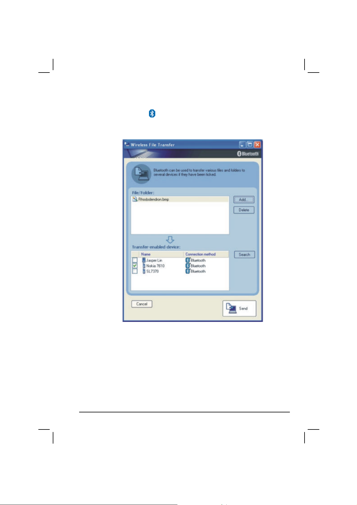
Sending a File
1. Right-click the icon, and then click Wireless File Transfer. The
following screen appears.
2. In the Wireless File Transfer window, click Add to browse for the file
to send. The file(s) will show on the File/Folder window.
3. Click the target device from the Transfer-enabled device window, and
then click Send to start the transfer procedure.
Operating Your Computer 2-31
Page 56

For detailed information on using the Bluetooth Utility, see the Bluetooth
Utility Help on your computer by clicking on Help, then Help . . .
2-32 Operating Your Computer
Page 57

CHAPTER
Managing Power
Your computer operates either on external AC power or internal battery
power.
This chapter tells you how you can effectively manage power. To
maintain optimal battery performance, it is important that you use the
battery in the proper way.
The topics in this chapter include:
l What is an AC adapter
l How to charge the battery pack
l When and how to initialize the battery pack
3
l How to check the battery level
l How to replace the battery pack
l What happens when the battery is low and what actions to take
l What is Power Management
l How to save power
Page 58

AC Adapter
CAUTION:
l The AC adapter is designed for use with your computer only. Connecting the AC
adapter to another device can damage the adapter.
l The AC power cord supplied with your computer is for use in the country where you
purchased your computer. If you plan to go overseas with the computer, consult
your dealer for the appropriate power cord.
l When you disconnect the AC adapter, disconnect from the electrical outlet first and
then from the computer. A reverse procedure may damage the AC adapter or
computer.
l When unplugging the connector, always hold the plug head. Never pull on the cord.
The AC adapter serves as a converter from AC (Alternating Current) to
DC (Direct Current) power because your computer runs on DC power,
but an electrical outlet usually provides AC power. It also charges the
battery pack when connected to AC power.
The AC adapter operates on any voltage in the range of 100 ~ 240 V AC.
3-2 Managing Power
Page 59

Battery Pack
The Li-ion battery pack is the internal power source for the computer
when the AC power is “Off” or not connected. It is rechargeable using the
AC adapter. The removable battery pack, with on-line charge capacity,
comes standard with your computer. It has 107 watt operating capacity.
The computer supports up to three Li-ion battery packs: Primary, Bay1,
and Bay2 (Bay1 and Bay2 are optional).
The operating time of a fully charged battery pack depends on how you
are using the computer. When your applications often access peripherals,
you will experience a shorter operating time.
NOTE: Care and maintenance information for the battery is provided in the “Battery
Pack Guidelines” section in Chapter 7.
Charging the Battery Pack
NOTE:
l Charging will not start if the battery’s temperature is below 0 °C (32 °F) or above
50 °C (122 °F).
l The charging process will stop when the battery’s temperature gets above 60 °C
(140 °F). If this happens, the battery pack may be damaged. Please contact your
dealer.
l During charging, do not disconnect the AC adapter before the battery has been fully
charged; otherwise you will get a prematurely charged battery.
To charge the battery pack, connect the AC adapter to the computer and
an electrical outlet. The Battery Charge Indicator ( ) on the computer
glows amber to indicate that charging is in progress. You are advised to
keep the computer power off while the battery is being charged. When the
battery is fully charged, the Battery Charge Indicator glows green.
The sequence of charging is Primary, then Bay1 and Bay2 battery packs.
Managing Power 3-3
Page 60

(2400 mah or more
The charging times are as follows:
Battery Type
per cell)
Primary (107 watt)
Bay1 (71 watt) 2.5 hours 3.5 hours
Bay2 (71 watt) 2.5 hours 3.5 hours
CAUTION: After the computer has been fully recharged, do not immediately disconnect
and reconnect the AC adapter to charge it again. Doing so may damage the battery.
NOTE: The battery level may automatically lessen due to the self-discharge process
(0.21 % per day), even when the battery pack is fully charged (100 %). This happens no
matter if the battery pack is installed in the computer.
Computer is Off Computer is On and
3.5 hours 4.7 hours
Charging Time
in Idle State
Initializing the Battery Pack
You need to initialize a new battery pack before using it for the first time
or when the actual operating time of a battery pack is much less than
expected.
Initializing is the process of fully charging, discharging, and then
charging. It can take several hours.
1. Make sure the computer power is turned off. Connect the AC adapter
to fully charge the battery pack.
2. After the battery pack is fully charged, turn on the computer.
3. Disconnect the AC adapter and leave the computer on until the
battery is fully discharged. The computer will shut down
automatically.
4. Connect the AC adapter to fully charge the battery pack.
3-4 Managing Power
Page 61

Checking the Battery Level
NOTE: Any battery level indication is an estimated result. The actual operating time can
be different from the estimated time, depending on how you are using the computer.
You can check the approximate battery level using the battery meter
function of the operating system. To read the battery level in Windows,
click the icon on the taskbar. (Click the icon if the computer is
using AC power.)
Replacing the Primary Battery Pack
CAUTION:
l There is danger of explosion if the battery is incorrectly replaced. Replace the
battery only with the computer manufacturer’s optional battery packs. Discard used
batteries according to the dealer’s instructions.
l Do not attempt to disassemble the battery pack.
If you often rely on battery power for a long period of time while
traveling, you may consider the purchase of an additional battery pack
from your dealer and keep it with you in a fully charged state as a backup.
To replace the primary battery pack, follow these steps:
1. Make sure the computer is not turned on or connected to AC power.
2. Locate the battery slot on the left side of the system.
3. Remove the two screws securing the battery pack to the computer.
Managing Power 3-5
Page 62
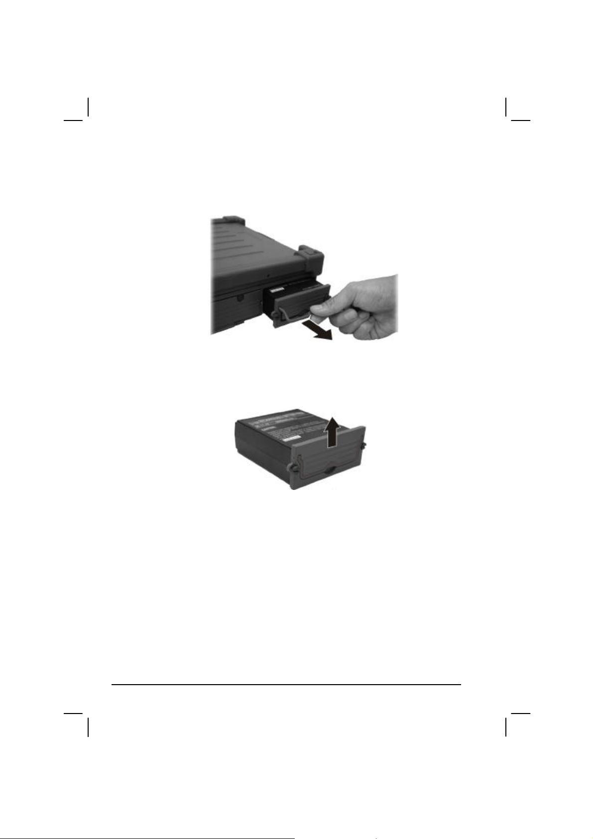
4. Lift up the handle and pull on it to slide the battery pack off the
computer.
5. Slide the front panel off the battery pack and replace it on a new
battery pack.
6. Slide the new battery pack into the computer.
7. Replace the two screws to secure the battery pack on the computer.
3-6 Managing Power
Page 63

Battery Low Signals and Actions
Battery Low occurs when the battery has approximately 10 % (Windows
default setting) of its charge remaining. The computer gives warning
beeps or messages and the Battery Power Indicator ( ) blinks amber
(orange) to alert you to take actions.
NOTE: You can set up your threshold and signals of Battery Low under Windows.
Immediately save your data upon Battery Low. The remaining operating
time depends on how you are using the computer. If you are using the
audio subsystem, hard disk drive, or PC card the battery might run out of
charge very quickly.
Always respond to Battery Low by placing your computer on Standby or
Hibernation mode, turning off the computer, or connecting the AC
adapter.
If you do not take any action, the computer will automatically hibernate
and turn off.
CAUTION: If you fail to save your data when the battery completely runs out of charge,
then you lose your data.
Managing Power 3-7
Page 64

Power Management
Your computer supports ACPI (Advanced Configuration and Power
Interface) for power management. The power management feature allows
you to reduce the power consumption for energy saving.
With an ACPI-compliant operating system such as Windows 2000 and
Windows XP, power supply to different computer components is
controlled on an as-needed basis. This allows maximum power
conservation and performance at the same time.
In general, Windows’ power management works in this way:
What… When…
Power to the hard disk is turned off When the hard disk has been idle for a
set period.
Power to the display is turned off When the display has been idle for a set
period.
The computer enters Standby mode.
The hard disk and display are turned
off and the entire system consumes
less power.
The computer enters Hibernation
mode. (See the next subsection for
more information.)
* depends on your settings in Windows.
When the entire system has been idle
for a set period.
When you press Fn+F12. *
When you close the cover. *
When you press the power button. *
When you press the power button. *
When you press Fn+F12. *
When you close the cover. *
For detailed information on power management, see Windows’ Help.
3-8 Managing Power
Page 65

Hibernation
Hibernation is a very useful feature. People frequently open many
applications when they use computers. It takes some time to get all these
applications open and running, and normally they all have to be closed
before the system can be turned off.
When you use the hibernation feature, you do not have to close the
applications. The computer stores the state of your computer to a file on
the hard disk and then shut down. The next time you turn on your
computer, you return to exactly where you left off.
Managing Power 3-9
Page 66

Power-Saving Tips
In addition to your computer’s automatic power management, you can do
your part to maximize the battery’s operating time by following these
suggestions.
l Do not disable Power Management.
l Decrease the LCD brightness to the lowest comfortable level.
l If you work with an application that uses a PC card, exit the
application when you finish using it.
l If you have a PC card installed, remove it when not in use. Some PC
cards drain power even while they are inactive.
l Deactivate the application that uses the serial port or features wireless
connectivity (LAN/WLAN/modem/GPS/Bluetooth) if you are not
using it.
l Turn off the computer when you are not using it.
3-10 Managing Power
Page 67

CHAPTER
4
Expanding Your Computer
You can expand the capabilities of your computer by connecting other
peripheral devices. When using a device, be sure to read the instructions
accompanying the device together with the relevant section in this
chapter.
This chapter gives guidelines on installing and using these devices:
l External monitor
l Parallel device
l Serial device
l IR device
l USB device
l IEEE 1394B device
l PC card
Page 68

Connecting an External Monitor
If you want the benefits of a larger display screen with higher resolution,
you can connect an external CRT monitor to your computer.
Follow this procedure to connect an external monitor:
1. Make sure that the computer is not turned on.
2. Plug the monitor’s D-type signal connector to the computer’s VGA
port.
3. Plug one end of the monitor’s power cord into the power socket on
the monitor and the other end to an electrical outlet.
4. To use the monitor, turn on the monitor before turning on the
computer.
5. The monitor should respond by default. If not, you can switch the
display to the monitor or to both (simultaneous display), or to
multi-display by pressing Fn+F9. In Windows, you can also change
the display through the settings in Display Properties.
6. You can change display settings through your operating system. See
your operating system documentation or online help for specific
information.
CAUTION: Do not disconnect the external monitor while the computer is in Standby
mode or Hibernation mode. If no external monitor is connected when the computer
resumes, the LCD remains blank and the output is not displayed.
NOTE: Make sure that the device driver is installed correctly (see chapter 6 for details) .
4-2 Expanding Your Computer
Page 69

Connecting a Parallel Device
Your computer has a
printer. The port supports ECP (Extended Capabilities Port) and EPP
(Enhanced Parallel Port) modes that turn the standard parallel port into a
high-speed bi-directional peripheral port.
Follow this procedure to connect a parallel device:
1. Make sure the computer is not turned on.
2. Plug the parallel device’s cable to the parallel port on the rear of the
computer.
parallel port for connecting a parallel device such as
3. If the parallel device has independent power, plug its power cord into
an electrical outlet.
4. If the parallel device has its own power switch, turn on the device
before turning on the computer.
Expanding Your Computer 4-3
Page 70

Connecting a Serial Device
Your computer has a serial port for connecting a serial device such as a
serial mouse or modem.
Follow this procedure to connect a serial device:
1. Make sure the computer is not turned on.
2. Plug the device cable to the serial port on the rear of the computer.
3. Turn on the computer.
NOTE: Portable modems that derive power through the serial port cannot be used with
the computer. Instead, use a modem that is powered by its own internal battery or
4-4 Expanding Your Computer
external AC power.
Page 71

Connecting an IR Device
Your computer has an IR (infrared) port for connecting an infraredequipped device wirelessly such as another computer, printer, or PDA
(Personal Digital Assistant).
When using the IR port of your computer to receive data:
Place the transmitting device where its IR port faces the IR port of your
computer within the effective range − within ±20-degrees vertical angle
and within ±20-degrees horizontal angle at no greater than 0.8~1.0 meter
distance.
When using the IR port of your computer to transmit data:
Place the receiving device where the IR port of your computer faces its IR
port within the effective range − within ±15-degrees vertical angle and
within ±15-degrees horizontal angle at no greater than 0.8~1.0 meter
distance.
To take advantage of the IR communications, you need third party
software.
Expanding Your Computer 4-5
Page 72

NOTE: During infrared communication, note the following:
l Do not move the computer and IR device.
l Do not enter Standby mode.
l Do not use a cell phone or another IR device near the computer.
l Avoid strong light such as sunlight or fluorescent light.
l Disable the screen saver.
4-6 Expanding Your Computer
Page 73

Connecting a USB Device
Your computer has two USB ports that supports transfer rates up to
12 MB/s for USB 1.1 devices and 480 MB/s for USB 2.0 devices, such as
digital camera, scanner, printer, modem, and mouse.
USB is specified to be an industry standard extension to the PC
architecture. It supports “Plug-and-Play” technology so you can install
and remove USB devices without turning off the computer. With its
multiple connection capability, up to 127 devices can be connected in a
daisy-chain configuration. In addition, you can use a USB hub that
converts a single USB connector into multiple ports where USB devices
can be connected.
To connect a USB device, simply plug the device cable to one of the USB
ports.
Expanding Your Computer 4-7
Page 74
Connecting an IEEE 1394B Device
NOTE:
l Your IEEE 1394B port will only function under Windows XP SP2. It is also Windows
Vista ready.
l Make sure that the 1394B driver is installed correctly (see chapter 6 for details).
l To connect an IEEE 1394A (also known as FireWire 400) device to the computer’s
IEEE 1394B (also known as FireWire 800) port, you need an optional FireWire
800/FireWire 400 bilingual cable.
Your computer has an IEEE 1394B port for connecting IEEE 1394B
devices.
IEEE 1394B is the next-generation serial bus standard, featuring
high-speed data transfer that doubles the throughput of the original IEEE
1394A interface (from 400 Mbit/sec to 800 Mbit/sec) and dramatically
increases the maximum distance of connections (up to 15 feet away,
while a FireWire 800 optical repeater will connect devices up to 1000
meters (3300 feet) away). It allows connection of up to 63 devices. The
applications include mass storage device, digital video (DV) camcorder,
or a digital audio device.
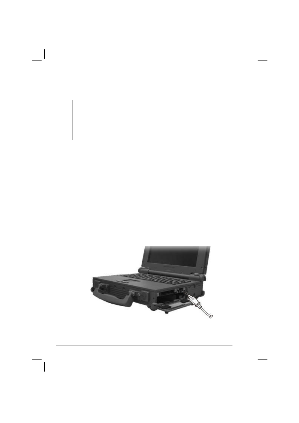
To connect an IEEE 1394B device, prepare an IEEE 1394B cable. Plug
the appropriate end of the cable to the computer’s IEEE 1394B connector
and the other end to the device’s corresponding connector.
4-8 Expanding Your Computer
Page 75

Using PC Cards
Your computer has a PC card slot.
PC cards are credit card-sized peripheral products based on the standards
developed by PCMCIA (Personal Computer Memory Card International
Association). PCMCIA is a non-profit association for promoting the
interchangeability among mobile computers where ruggedness, low
power, and small size are critical. Ever since its foundation, the
association has been continuing their efforts to add new specifications to
the PC card standard as new needs arise in the market.
PC Card Type
Your computer’s PC card slot can accommodate two type II cards or a
type III card. Type II cards are typically used for I/O devices such as
data/fax modems, LANs, and mass storage devices. Type III cards are
used for devices whose components are thicker, such as rotating mass
storage devices. Extended cards allow the addition of components that
must remain outside the system for proper operation, such as antennas for
wireless applications.
CardBus Support
Your computer’s PC card slot supports CardBus specifications. CardBus
is the 32-bit version of PC card technology. It allows speeds of up to
133 Mbps at 33 MHz. Typical applications are SCSI host bus and
high-speed network cards.
Inserting and Removing a PC Card
NOTE:
l Some PC cards require additional system resources. Before using such PC card,
you may have to free other system resources for the PC card.
l Although some PC cards can be inserted and removed without turning off the
computer, you cannot remove or install PC cards in the Standby mode.
Expanding Your Computer 4-9
Page 76

To insert a PC card:
1. Locate the PC card slot on the right side of the computer.
2. Slide the PC card, with its label facing up, into the slot until the eject
button pops out.
Eject Button
3. When a new card is seated, the computer will detect it and try to
install the appropriate driver. Follow the on-screen instructions to
complete the process.
To remove a PC card:
1. Double-click the Safely Remove Hardware icon on the taskbar and
the Safely Remove Hardware window appears on screen.
2. Select the PC card you want to disable from the list and click the Stop
button.
3. Push the eject button and the card will slide out slightly.
4. Pull the card out of the slot.
4-10 Expanding Your Computer
Page 77

System Memory Upgrade
You can upgrade your computer by changing system memory to a
maximum of 2 GB on the two 200-pin DDR2 SO-DIMM slots. However,
to avoid damage during the installation procedure, please ask your dealer
for help.
Expanding Your Computer 4-11
Page 78

4-12 Expanding Your Computer
Page 79

CHAPTER
5
Setup Configuration Utility (SCU)
SCU is a program for configuring the BIOS (Basic Input/Output System)
settings of the computer.
BIOS is a layer of software, called firmware, that translates instructions
from other layers of software into instructions that the computer hardware
can understand. The BIOS settings are needed by your computer to
identify the types of installed devices and establish special features.
This chapter tells you how to use the SCU program.
Page 80

When and How to Use the SCU Program
When to Use
You need to run the SCU program when:
l You see an error message on the screen requesting you to run Setup.
l You want to restore the factory default settings.
l You want to modify some specific settings according to the ha rdware.
l You want to modify some specific settings to optimize system
performance.
Starting SCU
NOTE:
l The Setup screens shown in this chapter are for your reference only. The actual
items or settings on your computer may differ.
l The Setup program may have been updated after the publication of this manual.
l The settings you select in your operating system might override similar settings in
Setup.
To run SCU, press F2 when the prompt appears in the lower left corner of
the screen during system startup. The prompt shows up on the screen for
only a few seconds. You must press F2 quickly. The SCU menu appears
as shown next.
5-2 Setup Configuration Utility (SCU)
Page 81

The SCU menu can be divided into four areas:
l On the top is the menu bar containing the titles of the available
menus. Each menu title brings a specific menu.
l The center column of the menu displays the current configuration
information of the system, devices, and memory items.
l The right column of the menu provides more detailed information
when a menu item is highlighted.
l On the bottom keyboard keys are displayed for navigating the screen.
Setup Configuration Utility (SCU) 5-3
Page 82

Moving Around and Making Selections
In most cases, you must go through two levels to complete the setting for
an item: menu title and submenu.
Use the keyboard to move around and make selections. A brief
description of keyboard usage is listed next:
Key Function
← , →
↑ , ↓
+, – Changes the value.
Enter 1) Brings up the sub-menu when available.
Esc 1) Displays the Exit menu.
F1 Displays help information.
F9 Changes the values to the setup defaults.
F10 Saves and exit the SCU program.
Selects a menu title.
Selects an item or option.
2) Opens or closes the option window when an item is selected.
2) Closes the option window if one is open.
5-4 Setup Configuration Utility (SCU)
Page 83

Main Menu
The Main menu contains the system date and time as well as the
IDE/SATA interface setting of the system.
System Time sets the system time.
System Date sets the system date.
IDE Channel 0 Master/Slave / SATA Port 0/1 sets the type of storage
device installed. The options are User, Auto, CD-ROM, ATAPI
Removable, None, IDE Removable, and Other ATAPI.
Setup Configuration Utility (SCU) 5-5
Page 84

Advanced Menu
The Advanced menu contains the hard disk drive heater as well as the
screen display setting during system boot-up.
HDD Heater sets if the system automatically turns on the built-in hard
disk drive heater for low temperature operation. The options are Enabled
and Disabled.
NOTE: Disable this item to conserve energy when using battery power.
Summary Screen sets if the system configuration would be displayed
onscreen during system boot-up. The options are Enabled and Disabled.
Boot-time Diagnostic Screen sets if the system diagnostic screen would
be displayed during system boot-up. The options are Enabled and
Disabled.
5-6 Setup Configuration Utility (SCU)
Page 85

Intel Menu
The Intel menu contains the LPC I/O devices and CPU thermal setting of
the system.
LPC Control Sub-Menu sets the items that control the configuration of
various LPC input/output devices that exists on the CRB as well as the
National 393 serial input/output devices.
CPU Thermal Control Sub-Menu sets the items that control various
CPU thermal parameters.
Setup Configuration Utility (SCU) 5-7
Page 86

Security Menu
The Security menu contains the security setting, which safeguard your
system against unauthorized use.
TPM Support enables or disables TPM (Trusted Platform Module)
support. The options are Enabled and Disabled.
NOTE: To use the TPM feature, the TPM driver supplied with your computer must be
installed (see chapter 6 for details).
5-8 Setup Configuration Utility (SCU)
Page 87

Boot Menu
The Boot menu sets the sequence of the devices to be searched for the
operating system.
The bootable devices will be automatically detected during POST and
shown here, allowing you to set the sequence that the BIOS uses to look
for a boot device from which to load the operating system.
A brief description of keyboard usage is listed next:
Key Function
↑ , ↓
+, – Changes the boot sequence.
1 to 4 Loads the default boot sequence.
f or r Specifies if the device is fixed (f) or removable (r).
X Moves the highlighted boot device from the “Boot priority order”
Shift + 1 Deactivates/activates the highlighted boot device on the “Boot
Selects (highlight) a boot device.
list to the “Excluded from boot order” list, and vice versa.
priority order” list. When a device has been deactivated, an “!”
(exclamation) symbol appears beside the item and system will
bypass it when detecting boot device during POST.
Setup Configuration Utility (SCU) 5-9
Page 88

Exit Menu
The Exit menu displays ways of exiting the SCU program. After finishing
with your settings, you must save and exit so that the changes can take
effect.
Exit Saving Changes saves the changes you have made and exits BIOS
Setup Utility.
Exit Discarding Changes exits BIOS Setup Utility without saving the
changes you have made.
Load Setup Defaults loads the factory default values for all the items.
Discard Changes restores the previous values for all the items.
Save Changes saves the changes you have made.
5-10 Setup Configuration Utility (SCU)
Page 89

CHAPTER
6
Installing Software Drivers
To take full advantage of the unique features of your computer, some
operating systems require custom software, known as drivers, to be
installed.
If you purchased the computer with Windows pre-installed, your dealer
may have already installed the drivers. If not, you need to install the
drivers using the driver disc supplied with your computer.
This chapter describes how to install the drivers.
Page 90

How to Use the Driver CD
NOTE:
• The drivers may have been updated after this manual was published. For driver
upgrade, please contact your dealer.
• You can always find README or document files on the driver CD. These files
contain the latest information from the software supplier. Please read the files
together with this chapter.
• This driver CD supports Windows 98, Windows NT, Windows 2000, Windows
XP,
and Linux operating systems only. You are recommended to install Windows
2000
Service Pack 4 when using Windows 2000 and Windows XP Service Pack 2
when
using Windows XP.
• The available items may differ according to your computer model and operation
system.
• Do not remove the driver CD when installing the driver.
An autorun program is provided on the driver CD to help you easily
install the drivers. As you insert the driver CD, the autorun program
automatically starts. If you need to start the program manually, run the
Autorun.exe program from the Setup directory of the driver CD.
6-2 Installing Software Drivers
Page 91

The main screen appears as shown next:
To install the necessary driver, just click on the particular option and
follow the onscreen instructions to continue and complete installation.
Device Driver Ensures the full function of the following drivers.
Install this main driver before installing the other
drivers. Upon clicking this button, the chipset, VGA,
audio, modem, and LAN drivers would be installed
one after the other.
TPM Allows you to use the TPM (Trusted Platform Module)
support for security.
OSD Installs the OSD (on screen display) utility that
provides a graphic display to indicate the current status
of certain operations.
NOTE: The OSD utility is an option for you. You can decide whether you would like
to have this utility installed. (See the next section for details.)
Installing Software Drivers 6-3
Page 92

Option Device Upon clicking on this, the following screen appears.
WLAN Installs the WLAN driver that allows your system to
connect wirelessly to the Internet.
Bluetooth Allows your computer to connect to Bluetooth
(option) -compliant devices. Refer to chapter 2 for detailed
instructions on using the Bluetooth feature of your
computer.
TouchScreen Allows you to use your fingers as a pointing device on
(option) the LCD screen (refer to the next section for further
instructions).
6-4 Installing Software Drivers
Page 93

Vehicle Dock Upon clicking this button on the first page, the
following screen appears.
Video Capture Allows you to connect a video capture device through
(option) the AV input port.
USB-to-COM Allows you to use the wireless modem and GPS
(option) features to transmit information wirelessly.
Installing Software Drivers 6-5
Page 94

Others Upon clicking on this on the first page, the following
screen appears.
IrDA Installs the Microsoft Hotfix driver for the optional
(option) ATi M54-CSP VGA controller.
NOTE: You need to install the IrDA driver if your system comes with the ATi
M54-CSP VGA controller and if you are using Windows XP Service Pack 2 only.
Dual Core Installs the dual core hotfix for Windows XP only.
1394B Allows your computer to connect to IEEE 1394B
device.
BT Calibration Installs the battery pack automatic calibration utility.
User Guide Upon clicking on this on the first page, allows you to
view the Operation Manual on screen.
NOTE: You need Adobe Acrobat Reader to open the manual file supplied on this
driver disc. Install the Adobe Acrobat Reader program if you do not have it on your
computer by clicking on Get Adobe Reader.
6-6 Installing Software Drivers
Page 95
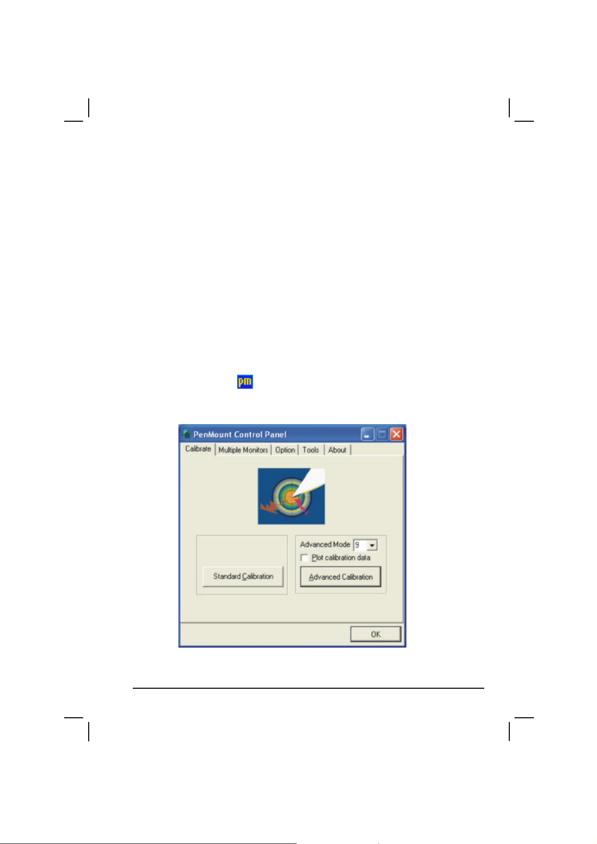
Browse CD Upon clicking on this on the first page, browses the
contents of the driver disc.
Exit Exits the driver installation.
Touchscreen Driver
To install the touch screen driver, perform the following:
1. Insert the driver disc into the optical drive.
2. Click on TouchScreen and follow the onscreen instructions to
continue.
3. When finished installing, select Yes to reboot your system. The driver
should now be loaded.
4. After the system has finished rebooting, click on the PenMount
Monitor icon located on the taskbar to bring up the PenMount
Control Panel.
Installing Software Drivers 6-7
Page 96

5. Click on Standard Calibration.
6. Click on the four sides (points) and the plus-sign “+” on the screen to
calibrate your touchscreen for use on the computer.
6-8 Installing Software Drivers
Page 97

Using the OSD
NOTE: The OSD utility is an option for you. You can decide whether you would like
to have this utility installed.
With the OSD utility installed, the utility will be activated and an icon will
appear on the system tray every time Windows starts up.
A graphic display will appear on the screen to indicate the current status
of certain operations (as listed next).
Hot Key/Button Operation
Icon
Fn+F3 Fn+F4 Mute
Fn+F5 Fn+F6
Fn+F7 Fn+F7
On Off
Fn+F9 Fn+F9 Fn+F9
LCD Both CRT
LCD Both DVI
OSD Description
Icon appears on the screen whenever you adjust
Windows or any of its application program’s
volume control (e.g., Windows Media Player,
etc.) to indicate the volume level. The OSD
disappears after a few seconds.
Icon appears on the screen to indicate the
brightness level. The OSD disappears after a
few seconds.
Icon appears on the screen to indicate that GPS
is on or off. The OSD disappears after a few
seconds.
Icon appears on the screen to indicate the
current display output. The OSD disappears
after a few seconds.
Installing Software Drivers 6-9
Page 98

Hot Key/Button Operation
Icon
Fn+F10/F11 Fn+F10/F11
On Off
On Off
AC In AC out
Speaker On Speaker Off
OSD Description
Icon appears on the screen to indicate that LCD
display (F10) or backlight (F11) is on or off.
The OSD disappears after a few seconds.
Icon appears on the screen to indicate that
wireless LAN is on or off. The OSD disappears
after a few seconds.
Icon appears on the screen to indicate that AC
power cord has been connected or unplugged.
The OSD disappears after a few seconds.
Icon appears on the screen to indicate that
speaker is on or off. The OSD disappears after
a few seconds.
Exiting and Reactivating the OSD Utility
To exit the OSD utility, right-click on the OSD utility icon on Windows
system tray and click on “Exit.”
To reactivate the OSD utility:
Double-click on the file OSD.EXE located on
c:/Program Files/OSD/ or
Restart the system.
6-10 Installing Software Drivers
Page 99

CHAPTER
Caring for the Computer
Taking good care of your computer will ensure a trouble-free operation
and reduce the risk of damage to your computer.
This chapter gives you guidelines covering these areas of maintenance:
l How to protect the computer
l What to note when using and storing the computer
l How to clean the computer
l What to note when using the battery pack
l What to note when traveling with the computer
7
Page 100

Protecting the Computer
To safeguard the integrity of your computer data as well as the computer
itself, you can protect the computer in several ways as described in this
section.
Using the Cable Lock
You can use a Kensington-type cable lock to protect your computer
against theft. The cable lock is available in most computer stores.
To use the lock, loop the lock cable around a stationary object such as a
table. Insert the lock to the Kensington lock hole and turn the key to
secure the lock. Store the key in a safe place.
Using an Anti-Virus Strategy
New viruses are always being developed nowadays and they are attacking
computers even more easily with emails so commonly used worldwide.
You can install a virus-detecting program to monitor potential viruses
that could damage your files.
7-2 Caring for the Computer
 Loading...