

Page 1
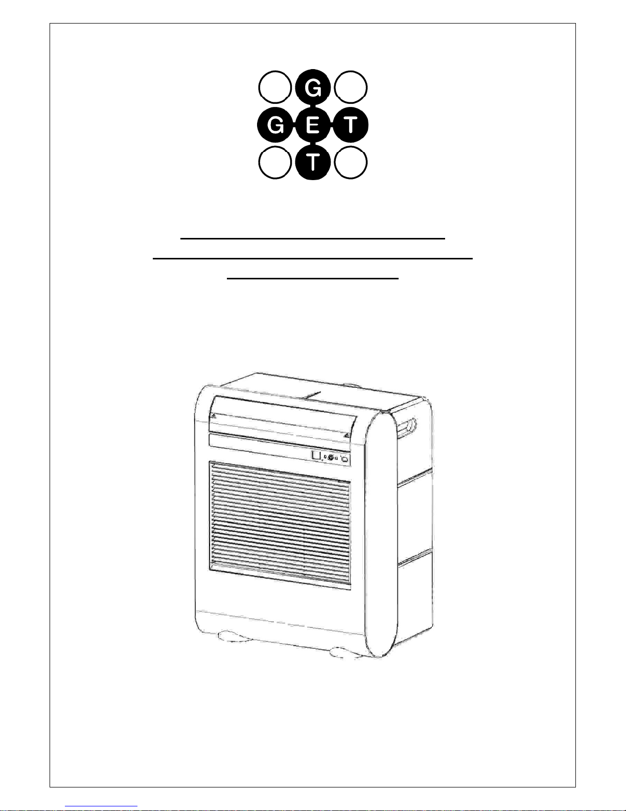
USER INSTRUCTIONS FOR GET
PORTABLE 6k BTU AIR CONDITIONER
MODEL No. GPACU6
Page 2
CONTENTS
Introduction
Safety Notes
Identification of parts
Installation instructions
Operation instructions
Troubleshooting
Maintenance
Energy saving tips
Specification
Page 3
Introduction
Thank you for choosing this portable air conditioner to provide you and your
family with all of the “Home Comfort” requirements for your home, or office.
The appliance can be moved from room to room within your home and set-up
in just minutes.
It is a multi-functional room air exchanging, air-processing appliance,
designed to offer you the functions of: Air Conditioning, Dehumidifying and
Independent Fan control.
This manual will provide you with valuable information necessary for the
proper care and maintenance for your new appliance. Read these instructions
fully before operating the unit and retain them for future reference. If properly
maintained your appliance will give you many years of trouble free operation.
Page 4
SAFETY NOTES
1. Do not connect to any AC socket outlet that is damaged.
2. Do not use in the following locations:Next to a source of fire.
An area where oil is likely to splash.
An area exposed to direct sunlight.
An area where water is likely to splash
Near a bath, shower or a swimming pool
In a greenhouse
3. Never insert your finger or any foreign objects into the air outlet or any other opening
on the machine. Take special care to warn children of these dangers.
4. Always store the unit upright in order to maintain the compressor in a proper working
condition. If not, leave the unit upright for at least 24 hours before operating.
5. Always unplug the unit before cleaning.
6. Do not cover the unit.
7. Do not place the back of the unit closer that 10cm from a wall.
8. Do not place the unit close to curtains or drapes in case they fall against the unit and
block the rear intake.
9. If the supply cord of this appliance becomes damaged, it must be replaced by a
qualified engineer.
10. This appliance is fitted with an approved BS 1363 13A 3 pin plug and a 13A BS 1362
fuse. In the event of either requiring replacement ensure that equivalent rated and
approved components are used. See plug replacement details below.
11. IMPORTANT:
installer must ensure that the air replacement is sufficient for both the unit used as an
air conditioner and the fuel burning appliance
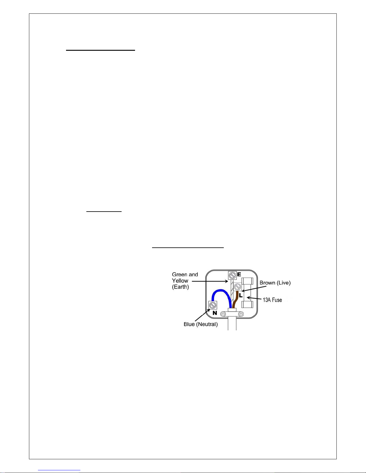
If the plug is damaged and requires replacement, follow the wiring instructions supplied with
the new plug.
1. The green and yellow wire must be
connected to the terminal marked with
the letter E or the earth symbol.
2. The blue wire must be connected to
the terminal marked with the letter N.
3. The brown wire must be connected
to the terminal marked with the letter L.
4. A 13 amp plug to BS 1363 must be
fitted with a 13 Amp fuse to BS 1362.
For your safety and protection, this unit is earthed through the power cord plug when plugged
into a matching earthed wall socket. If you are not sure whether the wall sockets in your
home are properly earthed, consult a qualified electrician. Do not use plug adaptors or
extension cords with this unit.
If this unit is sited in a room containing a fuel burning appliance, the
PLUG REPLACEMENT
Page 5
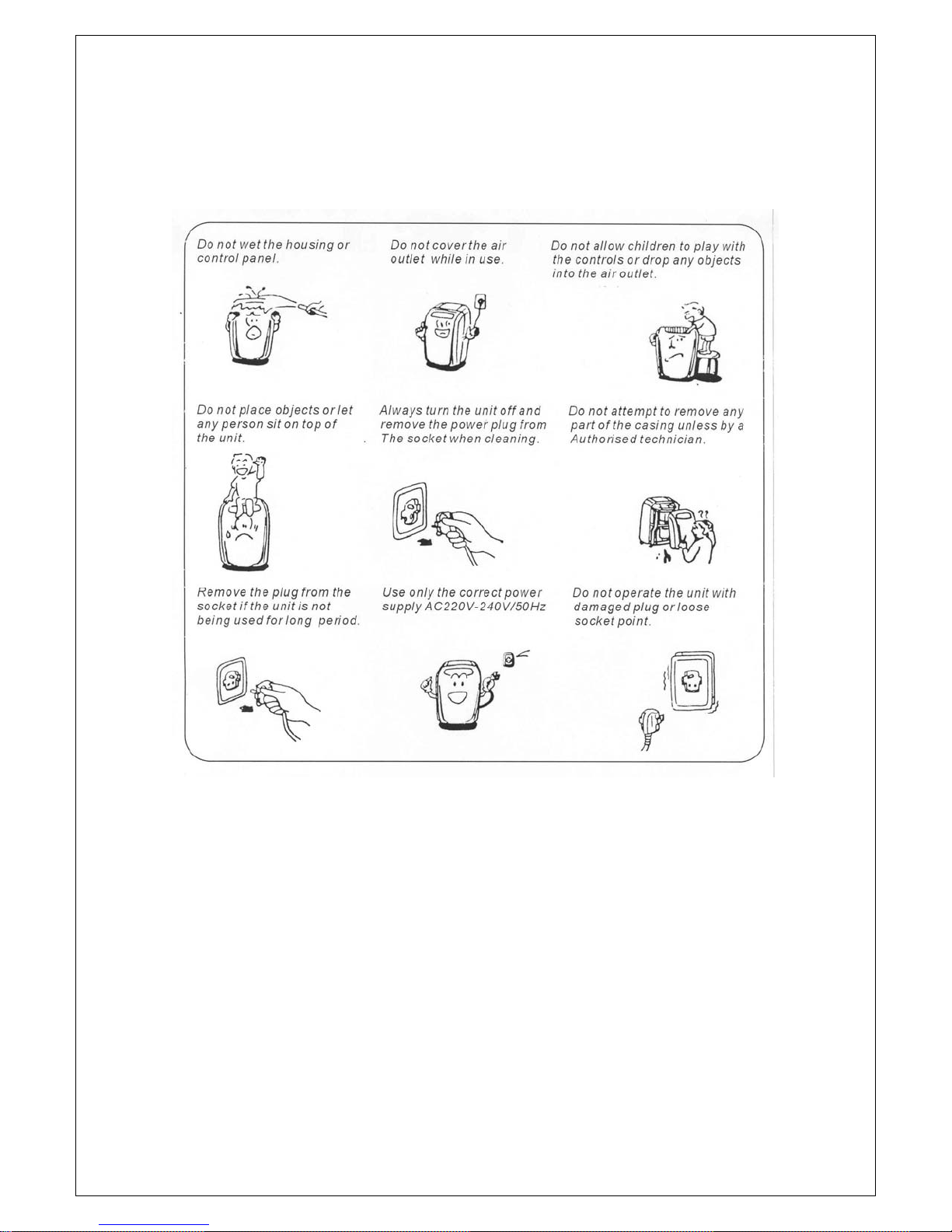
Warning
In order to ensure the long, reliable and safe functioning of the air conditioner,
the following safety points should be observed.
Page 6
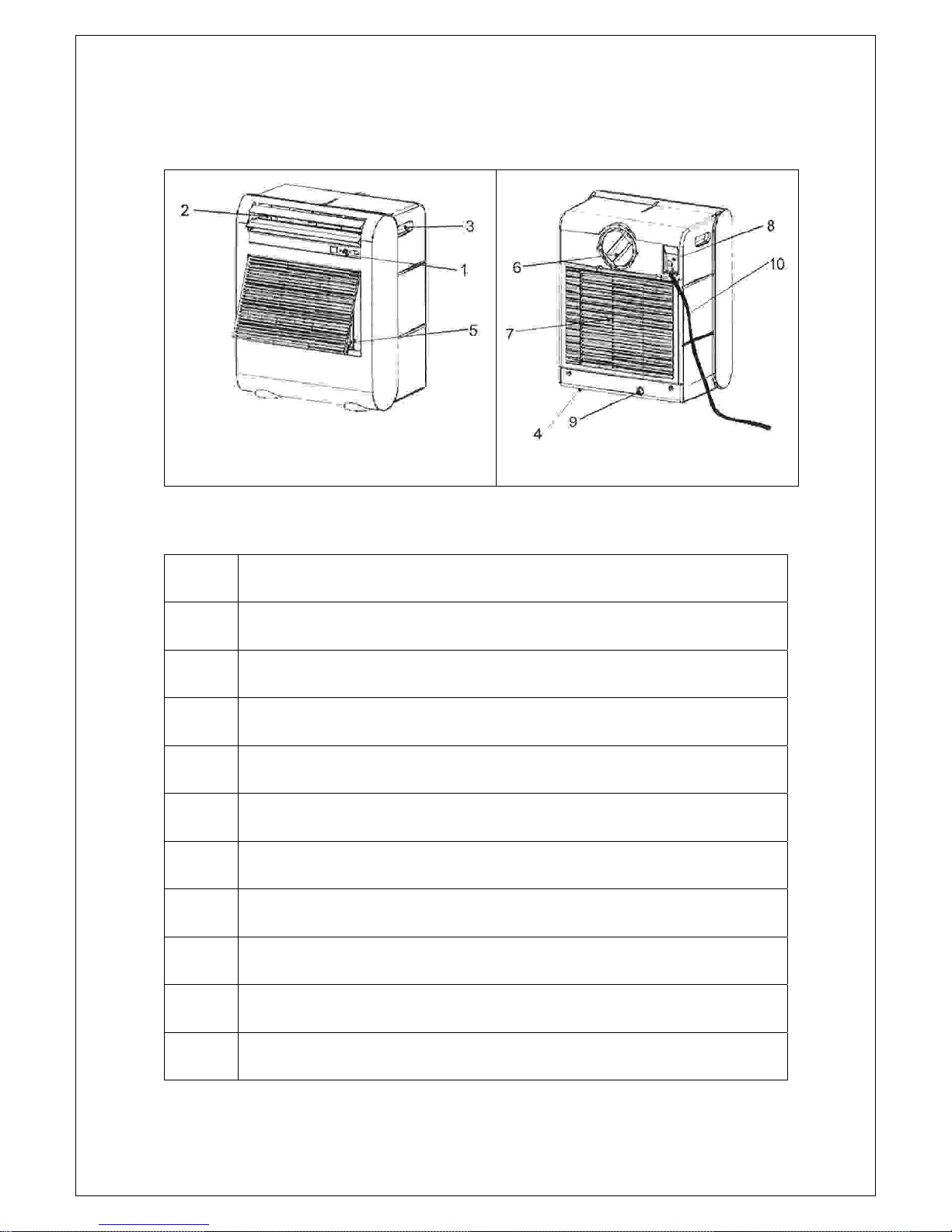
Identification of Parts
Front View
Rear View
Item
1
2
3
4
5
6
7
8
9
10
* Please manually open the air outlet (item 2) to desired position.
Description
Control Panel
Cool Air Outlet (*See note below)
Handle Recess
Castor
Air Filter
Exhaust Air outlet
Air Intake
Built-in Cable Storage
Water Drain / Outlet
Power Supply Cord
Page 7
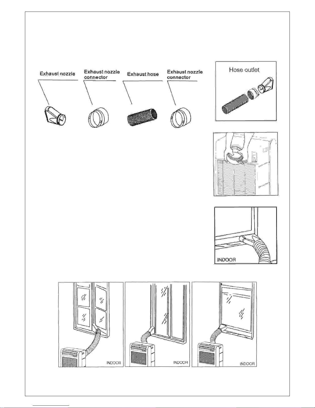
Installation
Items Supplied in Exhaust Hose Fitting Kit.
Assembly of the Exhaust Hose
The exhaust hose is assembled by fitting the exhaust nozzle connector to one
end of the hose and the exhaust duct connector to the other end of the hose.
This is done by screwing the connectors in an anti-clockwise direction onto the
ends of the hose.
The end of the hose fitted with the exhaust duct connector fitted is then
connected to the exhaust outlet at the back of the machine. Care should be
taken to ensure that the two rectangular cut-outs in the connector are located
over the two moulded fingers positioned on the diameter of the machine outlet.
The connector can be removed from the machine by rotating it slightly and
pulling it away from the machine at the same time.
The exhaust nozzle should be fitted to the exhaust nozzle connector on the free
end of the hose.
The hose should then be extended and the exhaust nozzle placed in an open
window to vent any warm or moist air extracted from the room, to the outside.
The window should be closed as far as possible to trap the nozzle as shown
below.
Page 8
Select a suitable location for the unit
• The unit should be positioned beside a window or door to allow the vent hose to
reach outside the room.
• The air intake should be a minimum distance of 10cm from any object.
• Do not install the unit underneath desks or inside cupboards as this will restrict the
operating air flow.
• Ensure that there are no obstructions to the air intake or air outlet.
• Ensure that the air intake is not being blocked by curtains, or similar objects.
• The end of the vent hose should not be blocked by a shutter or similar device.
• When fitting the vent hose it should be kept as straight as possible.
Page 9
Operation
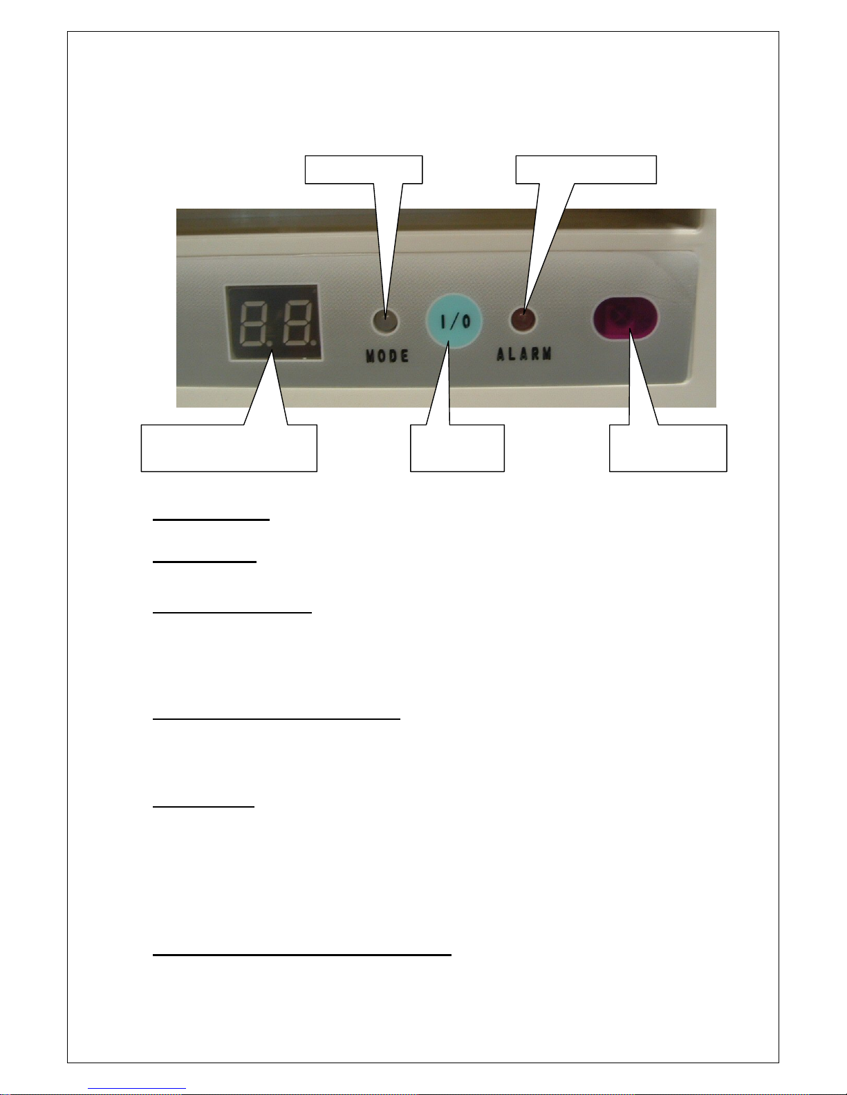
CONTROL PANEL
Mode Indicator Tank Full indicator
Temperature / Time
Setting Display Window
Power ON /
OFF Button
Remote Control
Sensor
CONTROLS
IMPORTANT:- Ensure that the draining bung is firmly in place in the
drain port before operating the machine.
Power ON / OFF Button
This button turns the unit on and off.
When the plug is first plugged into a socket the machine will bleep and go into stand-by
mode. Pressing the “Power” button will turn the machine on. Pressing the “Power” button
again will put the machine back into stand-by mode.
Note:- After switching the unit off, wait 3 minutes before switching it on again.
Tank Full Indicator (marked ALARM)
This LED will illuminate (Red) when the water tank within the machine is full and the machine
will stop. If after draining the tank, the warning light remains on, this could indicate that there
may be a fault with the machine. If this is the case, do not attempt to operate the machine
and call the service number.
Mode Indicator
Note:- Modes are selected by means of the remote controller.
a) When COOLING MODE is selected the LED will illuminate BLUE.
b) When DEHUMIDIFYING MODE is selected the LED will illuminate ORANGE.
c) When FAN MODE is selected the LED will illuminate GREEN.
Note:- In Cooling and Fan mode, the fan speed can be set to High, Medium and Low.
When Dehumidifying mode is selected the fan speed is automatically set to Low and
cannot be altered from this setting unless the room temperature is greater than 25°C.
Temperature / Time Setting Display Window
When the machine is running normally this shows the ambient room temperature.
This indicator is also used in conjunction with the remote controller to set the desired room
temperature and also the timer.
Page 10
Operation – cont’d
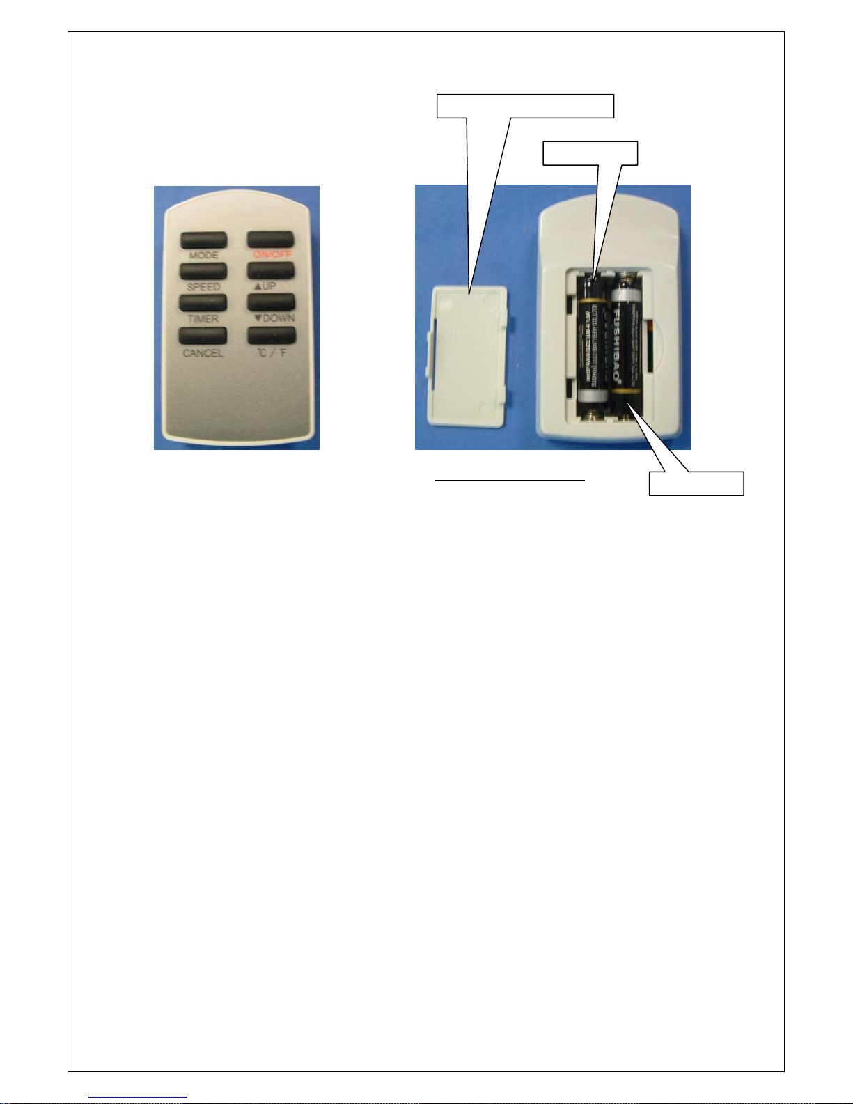
REMOTE CONTROLLER
Battery Compartment Lid
Battery +ve
Fit the batteries into the remote controller as shown above.
The remote controller can be used to switch the unit on and off up to a range of 10 metres
and is used to select the various modes and set the temperature or timer.
Note:- It is necessary for the remote controller to have a direct un-obstructed “line of sight”
with the front of the machine. If it is found that the remote controller does not always operate
the machine within the 10 metre range, this is an indication that the batteries may require
replacement. Replace with 2 new 1.5V, Size AAA batteries.
Dispose of the old batteries carefully - Do not expose to heat or fire.
BATTERY POSITIONS
Battery +ve
Function of Buttons on Remote Controller
ON / OFF Button
This button is used to switch the machine on and off.
MODE
This button is used to select the modes as follows:-
Cooling Mode (LED illuminates Blue)
In this mode the air is cooled and hot air is exhausted through the vent hose to outside the
room. Fan speed and temperature can be adjusted to suit the comfort level required by
means of the appropriate buttons on the remote controller.
Dehumidifying Mode (LED illuminates Orange)
Air is dehumidified as it passes through the air conditioner and the damp warm air should be
exhausted by means of the vent hose. If the room temperature is greater than 25°C, the fan
speed can be adjusted, otherwise the fan speed is fixed at low speed.
Note:- The warm air from the exhaust hose must be vented into the room when using
Dehumidifying mode and not outside the room as in cooling mode. If the unit is vented
outside the room some cooling will occur.
Page 11
Fan Mode (LED illuminates Green)
Air is cooled and circulated throughout the room. Note:- It is not necessary for the vent hose
to exhaust outside the room.
SPEED
This button is used to set the fan speed to Low, Medium or High. Note:- fan speed can not be
altered when in Dehumidifying mode unless the room temperature is above 25°C
Setting the Temperature
The temperature can be set by means of the ▲UP and ▼DOWN buttons on the remote
controller. Note:- It is only possible to set the temperature when in COOLING MODE.
The temperature can not be set when in DEHUMIDIFYING or FAN mode.
The temperature can be set between 16°C and 32°C and the temperature set will remain in
the Temperature / Time Display Window for approximately 5 seconds. The display will then
revert back to showing the current room temperature.
When the room temperature is higher than the display range, the display will show “HI”.
When the room temperature is lower than the display range, the display will show “LO”.
Setting the Timer
Press the Timer button on the remote controller to set the timer. The Temperature / Time
Display Window will flash for approximately 5 seconds and show the time that was last set on
the timer.
While the display is flashing, press the ▲UP and ▼DOWN buttons on the remote controller to
select the time (in hours, between 00 and 24) for either of the timer modes “a” or “b” as
detailed below. The time selected will be shown on the display panel and after approximately
5 seconds the display will revert to showing the room temperature.
Timer mode a) Auto Turn Off:- With the machine on and running, set the timer to select the
number of hours you would like the unit to run until it automatically shuts off.
Timer mode b) Auto Turn On:- Switch the machine on using the ON / OFF button (either
on the machine itself or on the remote controller) so that the machine is running and the
desired mode is selected. Press the ON / OFF button again to put the machine into stand-by
mode. Set the timer to select the number of hours until it is required for the machine to start
up automatically.
CANCEL Button
If the time has been set as in either “a” or “b” above and it is then decided that the timer is not
required, pressing the CANCEL button will turn the timer off.
°C / °F Button
Pressing this button will switch the display between degrees Celsius and degrees Fahrenheit.
IMPORTANT
When the appliance is in Cool or Dehumidifier mode, most moisture will be vented out
through the vent pipe. However, in certain circumstances some condensation may collect in
the water tank at the bottom of the chassis. When this tank is full, the “Tank full” indicator
(marked ALARM) will illuminate (red) and the appliance will stop running. The appliance
should then be unplugged from the supply socket and the rubber plug in drain port at the
lower rear
Alternatively, move the appliance to a suitable place to drain the water.
of the machine should be pulled out to drain the water into a suitable container.
Note: When the Tank Full light (marked ALARM) is on, the
water should be drained out. If the water is not drained out,
the appliance will not operate.
Page 12
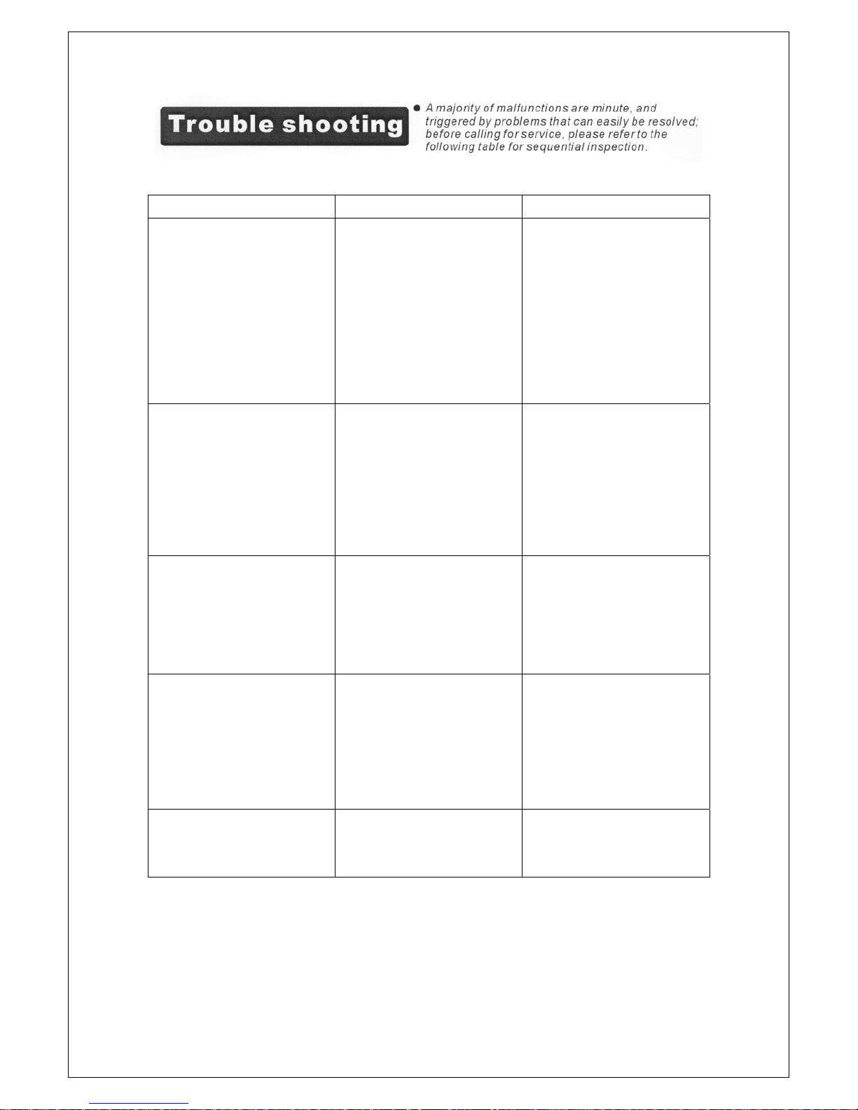
PROBLEMS REASONS SOLUTIONS
Air conditioner does not
operate.
Air conditioner suddenly
stops during operation.
Air conditioner runs
intermittently.
Air conditioner functions
but the room is not cooled.
Condensed water is
spilled out when moving
the unit.
Power has been cut off.
The plug has not been
plugged in properly.
The fuse in the plug has
blown
The Tank Full indicator
Is ON Tank is full
The indoor temperature
has reached the set
temperature level.
The preset time has
elapsed.
The air outlet is blocked
or obstructed.
The Tank Full indicator
is ON Tank is full.
Malfunction.
Surrounding
temperature is too high
or too low.
Heat exhaust hose is
blocked.
Window or door is left
open in the room.
There is a heat source
or too many people in
the room.
Filter is too dirty.
Temperature settings
are too high.
The tank is nearly full. Remove the draining
Wait for power to be
restored
Reset main MCB or
repair / replace main
fuse.
Plug in again.
Replace fuse in plug
Drain the water tank.
Reset the temperature
level.
Reset the timer.
Remove the obstruction
Drain the water tank.
Contact the service
centre.
Check the hose.
Close all windows and
doors.
Move any heat source
out of the room.
Clean the filter.
Lower the temperature
setting.
plug from the lower rear
of the unit. Drain the water
tank.
Page 13
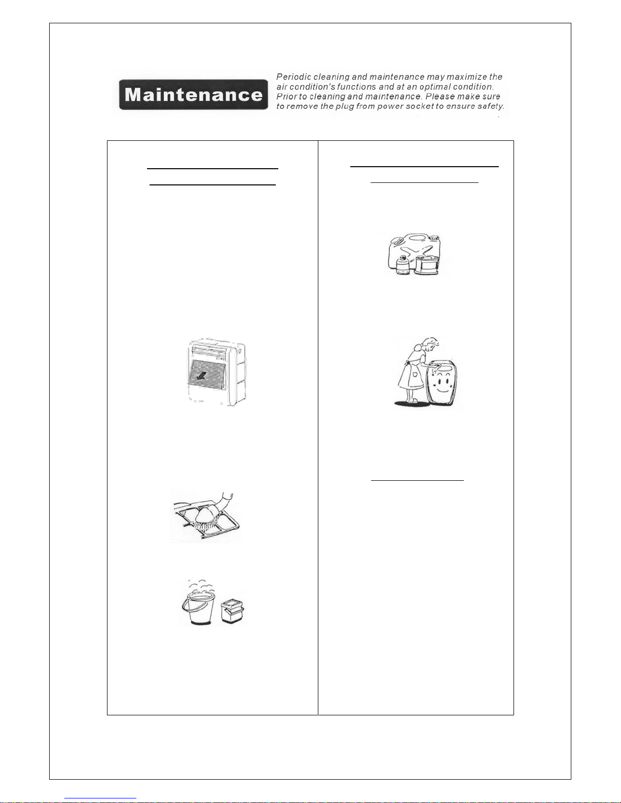
Regular Filter cleaning
Check every 2 Weeks
The air filter should be cleaned periodically.
The intervals between cleaning will depend on
the amount of airborne dust in the area in
which the unit is used but it would normally be
done every 2 weeks.
To gain access to the air filter it is first
necessary to remove the front grille. This is
done by pulling outwards at the bottom and
then pulling it downwards to disengage the
tabs at the top of the grille.
Maintenance on the front
panel and housing
Do not use chemicals or solvents for
cleaning the unit.
Use a damp cloth for cleaning. You may
use mild detergent to remove stubborn
stains.
The filter is located behind the grille and is
removed by unclipping the bottom edge and
pulling it down to release the top edge.
Use a vacuum or soft brush to remove fluff/dust
from the filter.
Wash the filter by immersing it gently in warm
water (about 40°C) with a neutral (or mild)
detergent.
Rinse the filter and allow to dry.
Replace the filter by engaging the top edge and
clipping the bottom into place.
Replace the front grille by engaging the
the top edge into the slots at the top of the
aperture of the front of the machine and clip the
bottom of the grille into place.
tabs on
Storing the Unit
If the appliance will not be used for a long
time, it is important to pull out the rubber
plug from the drain port at the lower rear of
the machine, in order to drain the water.
Run the machine in FAN mode for half a
day to dry out the internals of the machine.
Clean the air filter and reinstall it.
Remove the exhaust hose from the
machine and the batteries from the remote
controller. Keep them in a safe place.
Cover the unit and store in a dry place.
Page 14
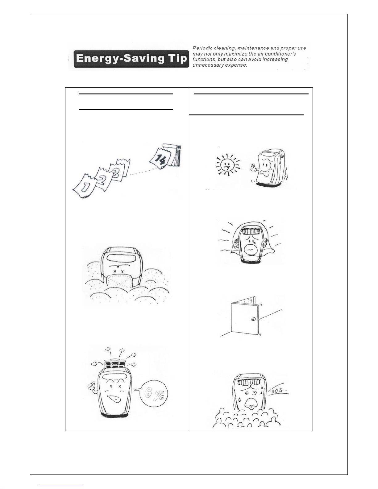
Clean the filter periodically
• When using it in normal conditions,
clean the filter at least once every
two weeks
• If you are using the unit in an area
with excessive dust/fluff make sure
you check and clean the filter each
week
Take note of the following
points
• Avoid direct sun light on the unit
through a window.
• Maintain proper ventilation around
the unit.
• If the filter is not kept clean it can
increase your power consumption
and reduce the cooling efficiency
• Avoid opening doors and windows as
much as possible.
• Avoid excess number of people in
the room
Page 15
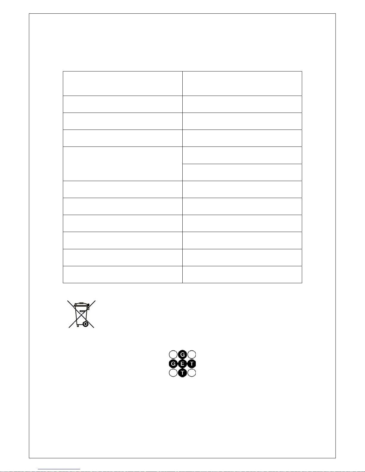
Specification
The figures below are for reference only and are based on practical operation
Performance may vary slightly depending on environmental conditions.
Description of product
Model
Voltage/Frequency
Input Power
Cooling capacity
Dehumidifying capacity
Coolant
Timer
Air flow volume
Dimensions (W) X (H) X (D)
Weight (N.W.)
NOTE:-
Waste electrical products or products containing refrigerants should not be
disposed of with household waste.
Please recycle where facilities exist. Check with your local authority or retailer
for recycling advice.
Portable Air Conditioner
GPACU6
AC 220-240/50Hz
700W
6000 B.T.U./Hr
1.8kW
1.4 L/hour
R-407C / 515g
24 hour
240m³/hour
485 X 612 X 337mm
25.3kgs
GET Plc, Key Point, 3-17, High Street, Potters Bar, Herts EN6 5AJ
Helpline Telephone no. 0121 565 7770
AR1247 Ed.C
 Loading...