


CAMERA TRACKING CONFERENCE SYSTEM
EG-6630M
【 】USER MANUAL

CAMERA TRAC KIN G CON FER ENC E SYS TEM
k you for using EG seri es conference system. Pleas e read
Th an
below instructio n careful ly before u sing this s ystem.
Please do not sc ratch/b and/twi st/pull /heat the powe r cable ,
otherwi se, it m ay cause damage to the power cable & even
cause fir e or electr ic shock.
Please do not op en the casing, o therwis e it may cause electric
shock. If this equipment needs checking/maintenance or
repair, please cont act our rep resenta tive.
Please do no t ret rofit this u nit, otherwi se, i t may cause fire or
electri c shock.
Please d o not t ouch t he power pl ug with your hands w et,
otherwi se, it may ca use elect ric shock .
If the power cable is w orn out (broke n or co re wire exposed),
please contact our rep resentative to get t he spare pa rt for
replace ment. It may cause fire or electric shock using the worn
out power c able.
Please disconnect the power ca ble fir st & th en disc onnect all
the conne cting cab le before y ou move thi s equipme nt.
If this unit is n ot using fo r a long time , please re move the power
plug from t he AC socket t o avoid une xpected f ire.
Caution
CAMERA TRAC KIN G CON FER ENC E SYS TEM
Contents
1.Functions. . . ... . . . . ... . . . . ... . . . . ... . . . . ... . . . ... . . . . .. 3
2.Front Pannel.. . . . . ... . . . . ... . . . . ... . . . . ... . . . . ... . . . . ... 4
3.Rear Pannel. . . ... . . . . ... . . . . ... . . . . ... . . . . ... . . . . ... . . . .4
4.Chairman Unit. . . ... . . . . ... . . . . .. . . . . ... . . . . ... . . . . ... . . .5
5.Delegate Unit. . . ... . . . . ... . . . . .. . . . . ... . . . . ... . . . . ... . . . 5
6.System Connection. . ... . . . . ... . . . . ... . . . . ... . . . . ... . . . . .6
7. Touch-screen Ope ration Instruction.. . . . . ... . . . . ... . . . . ... . .7
A.Conference Control. . . . . ... . . . . ... . . . . ... . . . . ... . . . . ..7
B.Camera Tracking.. . . . . ... . . . . ... . . . . ... . . . . ... . . . . ..11
C.Audio Recording. . ... . . . . ... . . . . ... . . . . ... . . . . ... . . . 14
D.System Setup.. . . . . ... . . . . ... . . . . ... . . . . ... . . . . ... .16
QR Code
E. . ... . . . . ... . . . . ... . . . . ... . . . . ... . . . . ... . . . .16
F.Restart. . . . ... . . . . ... . . . ... . . . . ... . . . . ... . . . . ... . . . 17
8.Webpage Operati on Instruction... . . . . .. . . . . ... . . . . ... . . . . .17
A.Unit Addressing.. . . . . ... . . . . ... . . . . ... . . . . ... . . . . ....19
B.Conference Setup.. . . . . ... . . . . ... . . . ... . . . . ... . . . . ... 20
C.Camera Tracking.. . . . . ... . . . . ... . . . . ... . . . . ... . . . . . .21
D.Conference Control. . . . . ... . . . . ... . . . . ... . . . . ... . . . . .23
E.Setup System.. . . . . ... . . . . ... . . . . ... . . . . ... . . . . ... . .26
F.System Password. . . ... . . . . ... . . . ... . . . . ... . . . . ... . . .26
G.Safe Logout. . . ... . . . . ... . . . . ... . . . . ... . . . . ... . . . ... 27
9.Connect ing with the Amplifier. . . ... . . . ... . . . . ... . . . . .. ... . 27
10.
PC software instruction . . ... . . . . ... . . . ... . . . . ... . . . . ... . 28
2

CAMERA TRAC KIN G CON FER ENC E SYS TEM
1.Main Feature
① Fully digital circuit des ign;
② Main controller adopts TF T capacitiv e touch- screen which makes
friendly interface & easy o peration.
③ With inserted control webpage, system can be controlled by po rtable
CAMERA TRAC KIN G CON FER ENC E SYS TEM
2.Front Panel of the Main Controller
devices like mobile phone/ Ipad/ PC. This can be done with out
software.
④With TCP/IP internet port to realize long-ran ge control. It can also
be connected to central con troller.
⑤ With RS232 port & USB port for se tting system parameter.
⑥ Au dio recording to d irectly. Th e aud io file in the
can be played.
⑦ Maximum 110 microphone units can be connect ed to one contr oller.
Maximum 15 main controlle rs can be cascaded.
⑧ Support pelco P/ D, YAAN, SONY EVI-D 70 camera protocol.
⑨ Support 6- in- 1- out video switch er. Maximum 6 cameras.
⑩ Maximum 5 g roups of preset po int for EVI- D70 can be saved to the
system.
⑪ Camera protoc ol can be via software by the user.
⑫ Meet mode: voice control, F IFO, chairman mode, all on mode .
⑬ Mic unit can be set time off or auto off.
⑭ With canon audio output & RCA jacks for li ne-in/out,Tel- in/ ou t.
⑮ Mic unit is free from mobile in terference & with hot-plug fu nction.
thumb dirve
edited
thumb dirve
1.TFT Touch-screen Display
Display the system config uration & working condition .
2.Power Switch
Turn on/o ff power for main con troller
3.Rear Panel of the Main Controller
1. AC power input socket & fuse ho lder. Power 220V.
2. Fuse holder: 2.5A fuse.
3. Camera connection port, v ia RS232.
4. Camera connection port, v ia RS485/RS422.
5. RS-232 port for PC.
6. RS232 port, for HDMI video sw itcher.
7. RS-232 port for central con troller.
8. TCP/IP network port: connect system with ne twork to realize remote
control via mobilephone /Ipad/PC.
9. USB port for audio recordin g.
10. USB po rt for PC.
11. Balance Out.
12. Line -in/out & Tel -in/out
13. 4 port s for maximum 110 mic units totally.
14. Casc ade port: for maximum 15 main con trollers.
3
4

CAMERA TRAC KIN G CON FER ENC E SYS TEM
4.Chairman Unit
1. Mic capsu le: to pick up the voice of speaker & s end it to amplifier
2. Mic light loop: to indicate t he working condition of the mic rophone
uilt-in loudspeaker
3. B
4. Priority button: to turn off all the delegate units
Mic button: to turn on or turn off the microphone
5.
Headset & built-in speake r volume control
6.
7. Display
7
5.Delegate Unit
1. Mic capsule: to pick up th e voice of speaker & send it to ampli fier
2.Mic li ght loop: to indicate the wor king condition of the microph one
3. Built-in loudspeaker
4. Mic button: to turn on or turn o ff the
microphone
5. Headset & built-in speak er volume control
6.Display
CAMERA TRAC KIN G CON FER ENC E SYS TEM
6.System Connection
6
6
Note:
The new installe d system can not be used u ntil every unit has been edit ed
address. Please refer to me nu “Edit Address”.
Please make sure to use the req uired power supply.
Avoid using this sy stem in dirty or dusty environm ent.
Avoid using this sy stem in high humidity environ ment.
5
6

CAMERA TRAC KIN G CON FER ENC E SYS TEM
CAMERA TRAC KIN G CON FER ENC E SYS TEM
7.Operation for Touch-screen
A.Conference Control
Click Conference Contro l to enter below interface:
Click “back” to go back, clic k to go to next page.
Meet Mode:
Discussion Mode: Camera t racks the last turned on unit.
Auto Mode: Camera tracks th e speaking unit.
Chairman Mode: Only chair man unit can be turned on.
All On Mode: All the units can be tu rned on. No limitation for spea king QTY.
Queue Mode:
FIFO & LIFO: Select first in fi rst out or for the queue.
last in first out
Sound Co ntrol(ON) & Soun d Contro l(OFF): to tu rn ON/OFF s ound control
function. If click sound control(ON), mic unit will be turned on whe n
speaking to the mic.
7
Click “back” to go back, clic k to go to next page as below:
8

CAMERA TRAC KIN G CON FER ENC E SYS TEM
CAMERA TRAC KIN G CON FER ENC E SYS TEM
Chairman QTY: To set the l imitation QTY for c hairman unit.
Speaking QTY: To set the l imitation for speaking unit s QTY.
Auto Off: To turn off t he microphone automatically i f the chair man or
delegate in certain time. 0S m eans this fu nction is
is no t opera ted
unavailable.
Time Off: to turn off th e microphone compulsively by the set certain time.
Click “back” to go back, clic k to go to next page as below:
Priority Tone: To play a tone when pressing the ch airman priority button.
Priority Setup: Manual Re cover, Auto Recover
Manual Recove r: Delegate units will be off when pressing th e chairman
priority once. Dele gate units need to be turned on manuall y by pressing the
ON/OFF button.
Auto Recover: D elegate un its will be off when long pr essing the chai rman
priority b utton. Delegate u nits wi ll be on again when re leasing the priority
button.
Card Meeti ng/Cardless Meeting: Whe n the mic uni ts adopt IC c ard port, this
is to set the requirement of me eting with IC card or not.
Click “back” to go back, clic k to go to next page as below:
Control Unit
All Unit: This is to co ntrol all the unit in the main controller.
Off: Turn off all the units.
On: Turn on all the unit s(Note: th is can only be carried ou t under “All On
Mode”.
Certain Unit: Turn on/off a certain unit by the related unit number.
Certain Unit Addressing: Addressing for additional unit. For example, when
there ar e 100 units for the system, input “101” & connect a new u nit to the
system th en click "Setup". The new u nit address will be “1 01” accordingl y.
Note: All the unit s' cables must be disconnecte d when setting.
All Unit Addressin g: Addressing all unit by entering a starting numb er. For
instance starting fro m number 1,click “setup”, by pressing the t urn on button
on each unit, the u nits will be set in default subsequent number. The first one
is unit num ber 1, foll owed by uni t number 2, unit numbe r will incr ease in an
ascending order till all units are set, and reboot main controller. (Normally
the process of unit address ing will be done prior to meeti ng)
9
10

CAMERA TRAC KIN G CON FER ENC E SYS TEM
CAMERA TRAC KIN G CON FER ENC E SYS TEM
Click “Camera” to setup cam era tracking parameter:
Volume Control: To adjust volume of audi o i nput and output, including Line
in/Line out/Un it speaker or headset/ Voice control. (When v oice control
function or limited speaking time mode is activat ed, the volume of unit voice
control is not allowed sett ing to the minimum level)
B.Camera
C a m e r a t y p e : P e l c o - D / P e l c o - P / S o n y ( b a u d rate:9 6 0 0 ) / Yaan(baud
rate:4800);
Address: Select needed ca mera to operate.
Focusing: Focus ra nge, the camera will adjust a utomatically, manual
operation can be applied wh en needed.
Rotate Rate: Rotation spe ed of the camera.
Clicking “back” to return last page, click left cursor to move backward or right
cursor to move forward to nex t page as below:
11
12

CAMERA TRAC KIN G CON FER ENC E SYS TEM
CAMERA TRAC KIN G CON FER ENC E SYS TEM
By clicking different direction button to control the m ovement of camera,
zoom in or zoom out button is use d in specific object focusing .
Setup Preset Point:
For example, the camera is set to focus on the posit ion of unit number 1,
enter desired preset number (here is 1) at the blank, click button “save
preset” to sa ve setup. Click left cursor to go back previous page to setup
the rest of unit c amera tracking position by following the same operation.
System de fault pre set point number is ze ro (0). wh en all units are off,
camera will set to track this specific position, normally it is th e full view of
the meeting room.
Clicking “back” to return last pag e, click left cur sor to move
backward or right cursor to m ove forward to next page as below :
When all units are set, it ca n be stored at this step as a proposal, multiple
proposals can store and ret rieve when needed.
C. Recording
The light loop of relative units will flash during preset point set up, to allow
operator to focus on spec ific unit easily. After sa ving the set up, clicking
button “Test pres et” to check if the preset poin t of specific unit is set
correctly.
Preview preset: To check all set preset po int of units
Delete all preset point: To delete all tracking poin t of set units
13
Press “S trat” to record during the meeting, t humb drive should be inserted
to the recording port at rear s ide of main controller to store v oice data.
14

CAMERA TRAC KIN G CON FER ENC E SYS TEM
CAMERA TRAC KIN G CON FER ENC E SYS TEM
The page of recording:
Audio recording pause:
D. System setup
Clicking “ System Setup” to setup language, IP address, time and main
controller ID.
The page of record playing:
15
Different ID should b e al located w hen mo re than one main controller are
cascaded. When only on e main cont roller is in use, main controll er ID
should set as 1. Default set tings, set to restore the fact ory settings, a ll the
parameters of the host will b e restored to factory paramet ers.
E.
Quick response code
By usi ng the scannin g soft ware of portab le devic es to scan the generated
QR code to instantly access t he webpage operation system .
16

CAMERA TRAC KIN G CON FER ENC E SYS TEM
F. System Restart
Clicking “Restart” to res tart the host.
CAMERA TRAC KIN G CON FER ENC E SYS TEM
User name: admin, default password:123456. ( User will log off the system
automatically after 10 mi nutes idle)
8.Webpage Operation Instruction
Set host's IP addre ss in th e same network segment with compute r
devices. For instance, when host's IP set a s 192.168.1.236, user
should key in the IP ad dress as above in explorer to login we bsite
operation system.
17
18

CAMERA TRAC KIN G CON FER ENC E SYS TEM
CAMERA TRAC KIN G CON FER ENC E SYS TEM
A.Unit Ad dressing
All Unit Addre ssing: Addressing all unit by entering a s tarting number. For
instance starti ng from number 1,click “set up”, by pressi ng the turn on
B.Conference Setup
Various paramete rs can be set in conference setup m anual as below:
FIFO & LIFO: Select first in fi rst out or last in last out for the q ueue.
button on each unit, the units will be set in default subsequent number. The
first one is unit number 1, followed by unit number 2, unit number will
increase in an a scending order till all units are set, and reboot main
controller.
Certain Unit Addressing: Addressing for additional uni t. For exam ple, when
there are 100 unit s for the system, input “101” & connect a new un it to the
system then click Setup. The new unit address will be “1 01” accordingly.
Note: All the unit s' cables must be disconnecte d when setting.
(Normally the process of un it addressing will be done pr ior to meeting)
19
Speaking QTY: To set the l imitation for speaking unit s QTY.
Sound Control(ON) & Sound Control(OFF): to turn ON/OFF sound control
function. If click sound control(ON), mic unit will be t urned on au tomatically
when speaking toward the mi c.
Meet Mode:
Discussion Mode: Camera t racks the last turned on unit.
Auto Mode: Camera tracks th e speaking unit.
Chairman Mode: Only Chair man unit can be turned on.
All On Mode: All units can be turn ed on. No limitation for speaki ng QTY.
20

CAMERA TRAC KIN G CON FER ENC E SYS TEM
Priority Setup: Manual Re cover, Auto Recover
Manual Recove r: Delegate units will be off when pressing th e chairman
priority once. Dele gate units need to be turned on manuall y by pressing the
ON/OFF button.
Auto Recover: D elegate un its will be off when long pr essing the chai rman
priority b utton. Delegate u nits wi ll be on again when re leasing the priority
button.
Auto Off: to turn off the microphone automatically if the chairman or
delegate do not s peak in certain time. 0S means t his function is not
activated.
Time Off: to turn off th e microphone compulsively by the set certain time.
Line In: adjust line in volum e
Line Out: adjust line out vol ume
C. Camera Tracking
In this section, m anual offered in computer vers ion and t ouch scree n
version fo r different platforms use purpose. Touch screen sensitivit y
adjustment was provided i n touch screen version.
CAMERA TRAC KIN G CON FER ENC E SYS TEM
Camera Type: Pelco-D/Pelco-P/Sony(baud rate:9600)/Ya a n ( b a u d
rate:4800);
Camera address: Select ne eded camera to operate.
21
Different ID should be allocated when more than one main controller are
cascaded. When only one main contro ller is in use, main controller ID should
set as 1.
Setup Preset Point:
For example, the camera is set to focus on the po sition of unit number 1,
enter desired preset number (he re is 1) at the unit column, click button
“Save Preset” to save setup. Following the rout ine to complete the rest
preset point setup. System default preset point number is z ero (0), when all
units o ff, camera will set to track this specific position, normally it is the full
view of the meet ing room. When clicking “Unit Light On”, the l ight loop of
currently o perated units will fl ash dur ing prese t point setup, to allow
operator to focu s on the unit easily. After saving the setup, c licking button
“Test Preset” to check if the pre set point of specific unit is set correctly.
22

CAMERA TRAC KIN G CON FER ENC E SYS TEM
CAMERA TRAC KIN G CON FER ENC E SYS TEM
D.Conference Control
Conference Unit Control
Units can be controlled individually in this sec tion. Unit status is i ndicated
in green when it is in use, clic k corresponding online unit number to turn
unit on or off.
In thi s sectio n, opera tor ca n key in the name o f rele vant att endees b y clicki ng
corresponding uni t number, then cli ck “ Save to device”to save as default
name list. When exit this page and go bac k this section, name list wi ll not
show au tomatically until clicking “Load name list”to retrieve default name
list. Firstly, cr eating a sp ecific tex t f ile in c omputer, select it from file path
column, to allow preset name list store t o or l oad from connected computer by
cl icking butt on“ Save to local”or“Lo ad fro m lo cal”To en able this
function, operator shou ld follow below steps to config ure computer:
St ep A: Configu re interne t expl or er setup :1 )Too ls 2)Inter ne t Opti on s
3)Security 4)Enter host I P into trusted sites; Unchec k “ Require server
verification (https: )f or all sites in this zone”
Note: If user is promptedwi th error, step B should be followe d after step A:
Unit Name List Management
23
Step B: Configure internet explorer setup: 1)Tools 2)Internet Options
3) Security 4) Custom level.Enable “ Initialize and scrip t Ac tiveX
controls not marked as safe for scr ipting”and “Include local dire ctory
path when uploading files t o a server”
24

CAMERA TRAC KIN G CON FER ENC E SYS TEM
CAMERA TRAC KIN G CON FER ENC E SYS TEM
E.Setup System
Setup system time and IP ad dress, system nee ds to restart after new IP
address is applied.
25
F.System Password
26
CAMERA TRAC KIN G CON FER ENC E SYS TEM
CAMERA TRAC KIN G CON FER ENC E SYS TEM
In this manual, administrator can add user t o system and change
password. The name of administrator i s fixed as admin, default password i s
123456. O nly adminis trator is authorized to make c hanging in this section.
As the ho st can be login by multiple devices at a time, thus default
administrator p assword sh ould change before use , relative users shou ld
add on the system group and dis tribute to corresponding pe rsonnel.
G.Logout system
Click “admin” located at up per right corner to logout syst em:
9.Connect Amplifier
Adjust the volume of amplifier to the minimum level and line ou t at 20.
Testing pe rsonnel need to speak toward the units while adjust the volume to
an appropr iate level . The position of speaker installation is i mportant, avoid
to place microphone units t oward speaker in case of howlin g effect occur.
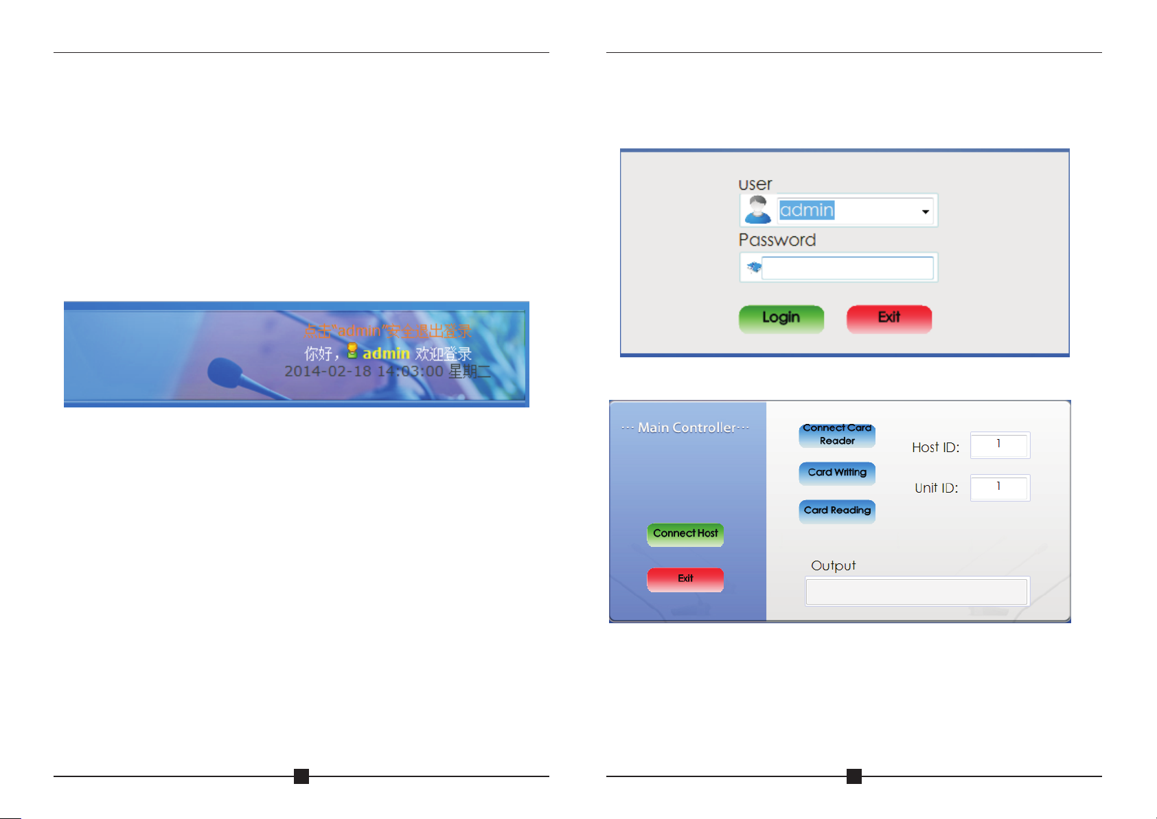
10.PC software instruction
Connect system with PC via USB port, then software will be installed
to PC automatical ly. Open file " Video confer ence system.exe ", to find
below interface:
Login (defaulted p assword is blank) to below inte rface:
27
Two options: Connect syste m or connect card reader
Card reader instruction :
1)Connect card re ader with PC via USB cable, then click “connect car d
reader”;
2)Click “card reading” to c heck card information;
3)Click “card writing” to i nput unit number & card holder in formation.
4)Label seat number & card ho lder name to each card after card w riting.
28

CAMERA TRAC KIN G CON FER ENC E SYS TEM
Voting system instruction:
Connect EG-6630M main controller with PC via USB cable, then click
“connect host”:
CAMERA TRAC KIN G CON FER ENC E SYS TEM
User Management
To set up user name, user passwor d & user department.
Conference System
Main controller setup
Click “host setting”-“a ll host parameter setup”to fi nd below interface:
29
1)Select t he number of host(main co ntroller) first, then select “activated” of
status for the chosen host;
2)Input the amount number of delegate units under “batch new”, then click
“batch new” to generate del egate list;
3)Input/modify delegate name then save it; Delegate name can be
displayed in the “Realtim e meeting”only.
4)Input registration number to the blank belo w “re gistration number” to set
attendees QTY of th e meeting.
5)When cascade multi controller, select the correspon ding number of host
& set all t he par ameter. Each time activating/d eactivating h ost, the
software need to be restart ed after finishing setup.
6)Input maximum 5 candidates name for election if necessary. Each
number of n ame in the software corr espond with number on the delegate
unit.
30

CAMERA TRAC KIN G CON FER ENC E SYS TEM
CAMERA TRAC KIN G CON FER ENC E SYS TEM
Unit Management
This is to edit & view delegate 's information.
Wireless voting sy stem setu p: This syst em can work with wireless voting
system.
Firstly set the host number in th e software corresponding to host ID of
wireless voting system ma in controller(from1-15) a nd activate host.
Setup for wireless v oting system i n the software is th e same as se tup fo r
conference system. Dele gate amount & attendees QTY must be set.
Please note that host ID for wireless voting syste m should be different with
host ID for conference syst em.
Line Checking
This is to check online unit of c onference system & wireless v oting system.
31
32

CAMERA TRAC KIN G CON FER ENC E SYS TEM
CAMERA TRAC KIN G CON FER ENC E SYS TEM
Venue Design
Venue Layout: Setup a simula tive conference hall for the me eting.
Realtime Meeting: Check u nit status & control meeting.
Venue Layout
1) Pa rameter Se tting: setup si ze for icon & se tup spacin g for quick layout
setup;
2) Quick set up one: input atte ndee QTY & QTY of each line to get layout;
3) Quick set up two: input QTY of each line & column to get layout;
4) Save current layo ut setup, then enter Real time Meeting to check unit
status.
Click ce rtain icon to turn on/off unit in inte rface of Realt ime Meet ing.
Meeting Mode
33
34

CAMERA TRAC KIN G CON FER ENC E SYS TEM
CAMERA TRAC KIN G CON FER ENC E SYS TEM
Meeting Mode:
Discussion Mode: Camera t racks the last turned on unit.
Auto Mode: Camera tracks th e speaking unit.
Chairman Mode: Only Chair man unit can be turned on.
All On Mode: All the units can be tu rned on. No limitation for spea king QTY.
Queue: Select first in firs t out or last in last out for the que ue.
Voice Control: to turn ON/OFF sound control fu nction. If click sound
control(ON), mic unit wil l be turned on when speaking to the m ic.
Priority Setup: Manual Re cover, Auto Recover
Manual Recover: Delegate unit s will be off when pressing the chairm an
priority once. Dele gate un its need to be turn ed on manually by pres sing
the ON/OFF button.
Auto Recover: Delegate units will be off when long press ing t he ch airman
priority button. Delegate units will be on again when releasing the priority
button.
Meeting:
Card: to hold the meeting wit h IC card.
Cardless: to hold the meeti ng without IC card
Unit Speaker: To turn on/off speaker
Buzzer: To turn on/off buzze r in the main controller.
Priority Tone: To turn on/off the to ne when using chairman priori ty.
Speaking QTY: to setup the max imum of speaking units.
Speaking QTY: to setup the maximu m QTY of speaking units(including
Chairman).
Chairman QTY: to setup the max imum QTY of speaking chairman unit.
Note: Chairman QTY can be more than speaking QTY.
Auto Off: to turn off the microp hone automaticall y if the chai rman or
delegate do not speak in certain time. 0S means this function is not
activated
Time Off: to turn off th e microphone compulsively by the set certain time.
Advanced Setup
Defaulted password is bla nk.
All unit addressin g: addres sing all unit by en tering a starting number. For
instance starting from number 1,click “setup”, by pressing the turn on
button on each unit, the units will be set in d efault subsequent number.
The first one is unit number 1, followed by unit number 2, un it nu mber will
increase i n an ascending order till all units a re set, and reboot ma in
controller. (Normally the process of un it addressing will be done
during installation, no need to setup during operati on)
Certain Unit Address ing: Addressing for additional unit. Fo r example, when
there are 100 units for the system, input “101” & connect a new unit to the
system then click Setu p. The new unit add ress will be “101” accordingly.
Note: All the unit s' cables must be disconnecte d when setting.
Host ID setup: Firstly connect only o ne contro ller to PC, then re vise host ID
and restart controller.
Camera Tracking
C a m e r a type: P e l c o - D / P e l c o - P / S o n y ( b a u d r a t e : 9 6 0 0 ) / Ya a n ( b a u d
rate:4800);
Camera address: Select ne eded camera to operate.
Different I D should be allocated when more than one main controller ar e
cascaded. When onl y one main controller is in use, main controller ID should
set as 1.
Setup preset point:
For example, the camera is se t t o f ocus on the position of unit number 1,
enter desired preset n umber (h ere is 1) at the unit col umn, cli ck butto n “Save
Preset” to save setup. Following the routine to complete the rest preset p oint
setup. System default preset point number is zer o (0), wh en all units off,
camera w ill set to track th is specific positi on, normal ly it is the full view of the
meeting room. When c licking “Unit Light On”, the ligh t loop of currently
operated units wi ll flash during pr eset point setup, to allow operator to focus
on the unit easily. Af ter saving the setup, clicki ng button “Test Pr eset” to
check if the preset point of sp ecific unit is set correctly.
35
36

CAMERA TRAC KIN G CON FER ENC E SYS TEM
CAMERA TRAC KIN G CON FER ENC E SYS TEM
Voting System
Voting Management
To setup attendee data for sign in. A ttendees must sign in first, so tha t they
can vote.
Proposal & Voting
Setup new voting propo sal in below interface. I nput subject, content , & other
voting data to the proposal . Voting setting can limit certa in attendee to vote.
After setup new proposal, c lick “Save” to generate propo sal.
37
Multiple proposa ls can be set in the software. Eac h proposal ca n be selected
to vote after sign in.
38
CAMERA TRAC KIN G CON FER ENC E SYS TEM
CAMERA TRAC KIN G CON FER ENC E SYS TEM
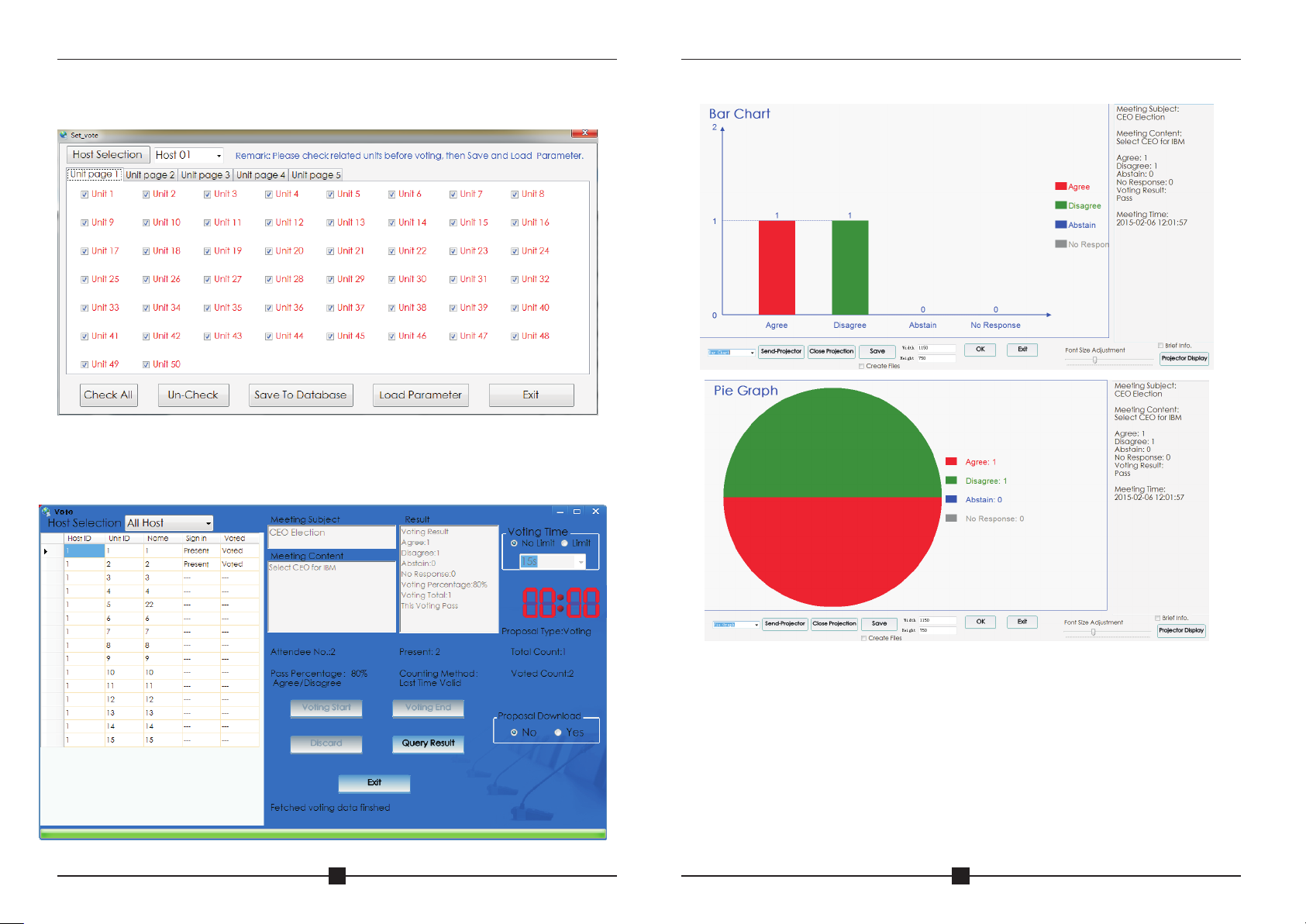
Voting Setting : Those un-check units can't vote for the proposal . Click
Save To Database or Loa d Parameter to realize limita tion.
Enter Voting
Click Enter Voting to en ter be low in terface. Click Voting Start to st art
voting & Click Result to get vo ting result.
Result
39
Two kind of graph as above to show voting res ult. Projector ca n show the
result with or without grap h. Result can also be saved as file .
Voting procedure:
1. Use “Line Checking” to che ck all the units, then setup Atten dees QTY.
2. Sign in.
3. Setup/select a proposa l, then enter voting—start vo ting—result.
4. Save voting resu lt.
40
 Loading...