

Page 1
Setup Guide
Read this manual carefully before you use this product and keep it handy for future
reference.
For safety, please follow the instructions in this manual.
Page 2

Introduction
This manual contains detailed instructions on the operation and maintenance of this machine. To get
maximum versatility from this machine all operators should carefully read and follow the instructions in
this manual. Please keep this manual in a handy place near the machine.
Please read the Safety Information before using this machine. It contains important information related
to USER SAFETY and PREVENTING EQUIPMENT PROBLEMS.
Power Source
120 V, 60 Hz, 10 A or more
Please be sure to connect the power cable to a power source as above.
Operator Safety:
This machine is considered a CDRH class I laser device, safe for office/ EDP use. The machine contains 7 milliwatt, 645 - 660 nanometer wavelength, AlGaInp Laser Diode. Direct (or indirect reflected)
eye contact with the laser beam might cause serious eye damage. Safety precautions and interlock
mechanisms have been designed to prevent any possible laser beam exposure to the operator.
Laser Safety:
The Center for Devices and Radiological Health (CDRH) prohibits the repair of laser-based optical unit
in the field. The optical housing unit can only be repaired in a factory or at a location with the requisite
equipment. The laser subsystem is replaceable in the field by a qualified Customer Engineer. The laser
chassis is not repairable in the field. Customer engineers are therefore directed to return all chassis
and laser subsystems to the factory or service depot when replacement or the optical subsystem is required.
Important
Parts of this manual are subject to change without prior notice. In no event will the company be liable
for direct, indirect, special, incidental, or consequential damages as a result of handling or operating
the machine.
Caution:
Use of controls or adjustment or performance of procedures other than those specified in this manual
might result in hazardous radiation exposure.
Do not attempt any maintenance or troubleshooting other than that mentioned in this manual. This
printer contains a laser beam generator and direct exposure to laser beams can cause permanent eye
damage.
Two kinds of size notation are employed in this manual. With this machine refer to the inch version.
For good copy quality, the supplier recommends that you use genuine toner from the supplier.
The supplier shall not be responsible for any damage or expense that might result from the use of parts
other than genuine parts from the supplier with your office products.
Page 3

Trademarks
Microsoft, Windows, and Windows NT are registered trademarks of Microsoft
Corporation in the United States and/or other countries.
IPS-PRINT Printer Language Emulation Copyright 1999-2000, XIONICS DOCUMENT TECHNOLOGIES, INC., All Rights Reserved.
Ethernet is a registered trademark of Xerox Corporation.
Other product names used herein are for identification purposes only and might
be trademarks of their respective companies. We disclaim any and all rights involved with those marks.
Notes:
Some illustrations might be slightly different from your machine.
Certain options might not be available in some countries. For details, please contact your local dealer.
Note
The proper names of the Windows operating systems are as follows:
•Microsoft
•Microsoft
•Microsoft
•Microsoft
•Microsoft
•Microsoft
•Microsoft
®
Windows® 95 operating system
®
Windows® 98 operating system
®
Windows® Millennium Edition (Windows Me)
®
Windows® 2000 Professional
®
Windows® 2000 Server
®
Windows NT® Server operating system Version 4.0
®
Windows NT® Workstation operating system Version 4.0
i
Page 4

Safety Information
R
R
When using your equipment, the following safety precautions should always be
followed.
Safety During Operation
In this manual, the following important symbols are used:
WARNING:
Indicates a potentially hazardous situation which, if instructions
are not followed, could result in death or serious injury.
CAUTION:
Indicates a potentially hazardous situation which, if instructions are not
followed, may result in minor or moderate injury or damage to property.
R WARNING:
• Connect the power cable directly into a wall outlet and never use an
extension cable.
• Confirm that the wall outlet is near the machine and freely accessible,
so that in event of an emergency, it can be unplugged easily.
• Disconnect the power plug (by pulling the plug, not the cable) if the
power cable or plug becomes frayed or damaged.
• To avoid hazardous electric shock or laser radiation exposure, do not
remove any covers or screws other than those specified in this manual.
• Turn off the power and disconnect the power plug (by pulling the
plug, not the cable) if any of the following conditions exist:
• You spill something into the equipment.
• You suspect that your equipment needs service or repair.
• Your equipment's cover has been damaged.
• Do not incinerate spilled toner or used toner. Toner dust is flammable
and might ignite when exposed to an open flame.
• Disposal should take place at an authorized dealer or appropriate collection site.
• If you dispose of the used toner containers yourself, dispose of them
according to local regulations.
ii
Page 5

R CAUTION:
• Protect the equipment from dampness or wet weather, such as rain, snow,
and so on.
• Unplug the power cable from the wall outlet before you move the equipment. While moving the equipment, you should take care that the power cable will not be damaged under the equipment.
• When you disconnect the power plug from the wall outlet, always pull the
plug (not the cable).
• Do not allow paper clips, staples, or other small metallic objects to fall inside the equipment.
• Do not eat or swallow toner.
• Keep toner (used or unused) and toner cartridge out of reach of children.
• For environmental reasons, do not dispose of the equipment or expended
supplies at a household waste collection point. Disposal should take place
at an authorized dealer or an appropriate collection site.
• Our products are engineered to meet the highest standards of quality and
functionality. When purchasing expendable supplies, we recommend using
only those specified by an authorized dealer.
• The inside of the machine becomes very hot. Do not touch the parts with a
label indicating a “hot surface”. Touching a “hot surface” could result in a
burn. (
v
: means "hot surface".)
iii
Page 6
ENERGY STAR Program
As an ENERGY STAR Partner, we have determined
that this machine model meets the ENERGY STAR
Guidelines for energy efficiency.
The ENERGY STAR Guidelines intend to establish an international energy-saving system for
developing and introducing energy-efficient office equipment to deal with environmental issues, such as global warming.
When a product meets the ENERGY STAR Guidelines for energy efficiency, the Partner shall
place the ENERGY STAR logo onto the machine model.
This product was designed to reduce the environmental impact associated with office equipment by means of energy-saving features, such as Low-power mode.
❖❖❖❖ Low-power Mode (Energy Saver mode)
This printer automatically lowers its power consumption 60 minutes after the
last operation has been completed. To exit Low-power (Energy Saver) mode,
press any key on the operation panel. For details about how to configure Energy Saver mode, see “Making Printer Settings with the Operation Panel” in Administrator Reference 2 as a PDF file on the CD-ROM.
❖❖❖❖ Specifications
Energy Saver mode Power Consumption 45 W or less
Default Time 60 minutes
Recovery Time 120 seconds or less
iv
Page 7

How to Read This Manual
R
R
Symbols
In this manual, the following symbols are used:
WARNING:
This symbol indicates a potentially hazardous situation which, if instructions
are not followed, could result in death or serious injury.
CAUTION:
This symbol indicates a potentially hazardous situation which, if instructions
are not followed, may result in minor or moderate injury or damage to property.
* The statements above are notes for your safety.
Important
If this instruction is not followed, paper might be misfed, or data might be lost.
Be sure to read this.
Preparation
This symbol indicates the prior knowledge or preparations required before operating.
Note
This symbol indicates precautions for operation, or actions to take after misoperation.
Limitation
This symbol indicates numerical limits, functions that cannot be used together,
or conditions in which a particular function cannot be used.
Reference
This symbol indicates a reference.
[]
Keys that appear on the machine's panel display.
Keys and buttons that appear on the computer's display.
{}
Keys built into the machine's operation panel.
Keys on the computer's keyboard.
v
Page 8

TABLE OF CONTENTS
1.Getting Started
Features of this Printer ............................................................................. 1
Guide to the Printer................................................................................... 2
Exterior: Front View....................................................................................... 2
Exterior: Rear View ....................................................................................... 3
Inside............................................................................................................. 4
Operation Panel ............................................................................................ 5
2.Setting Up
Where to Put the Printer ........................................................................... 7
Checking the Contents of the Box......................................................... 10
Unpacking the Printer ............................................................................. 12
Installing the Fuser Oil Unit.................................................................... 14
Installing Options .................................................................................... 16
How to Use the Screwdriver........................................................................ 20
Installing the Paper Feed Unit..................................................................... 20
Installing the Memory Unit Type B (SDRAM Module) ................................. 29
Installing the 1394 Interface Unit Type1045................................................ 31
Installing the User Account Enhance Unit TypeB ....................................... 34
Installing the Printer Hard Disk Type 3800C ............................................... 37
Installing the Duplex Unit Type 3800C........................................................ 41
Installing the SR770 (2 Tray Finisher)......................................................... 47
Installing the Mail Bin Type 3800C (4-bin Mailbox) ..................................... 54
Installing the Toner Cartridge ................................................................ 58
Loading Paper.......................................................................................... 60
Loading Paper in Tray 1 .............................................................................. 60
Tray 2 (Standard), 500-sheet Paper Feed Unit, 1000-sheet Paper Feed Unit
2000-sheet Large Capacity Tray................................................................. 65
... 61
Turning the Power On............................................................................. 66
Selecting the Panel Display Language.................................................. 67
Test Printing............................................................................................. 68
Connecting the Printer............................................................................ 69
Connection to a Network............................................................................. 69
Parallel Connection ..................................................................................... 70
INDEX........................................................................................................ 71
vi
Page 9

1. Getting Started
Features of this Printer
❖❖❖❖ High Productivity of 28 ppm in Full Color
This printer comes with a four-tandem engine which enables the high performance output of 28 ppm (pages per minute) in full color. You can print conference records, sales promotion ads, etc. in full color, as you would do with
a monochrome printer. And because the first print speed is less than 9.0 seconds, you will feel the difference in speed not only from multiple prints, but
even from the first. The printer's monochrome speed of 38 ppm is equivalent
to that of a high-speed monochrome laser printer, enabling you to use this
printer as your high performance network printer for both color and monochrome printing.
❖❖❖❖ High Image Quality Output in True 1200 dpi
True 1200 dpi resolution makes it possible for this printer to output text documents, documents containing images that are read in with a digital camera
or scanner, and graphics in fine detail. This high resolution can be output at
the speed of 14 ppm.
❖❖❖❖ Versatile Options with the New Generation Controller
With the new high-speed, 64-bit controller architecture and the new RPCS
command system, optimized for Windows software, this printer can output
at top speed. You can also use "Locked Print
*1
", where the printer does not
output unless a password is entered, or manage the number of printings and
limit the number of use per user
*2
. This printer answers the controller's
needs that only a color printer can do.
*1
Optional Printer Hard Disk is required.
*2
Optional User Account Enhance Unit is required.
❖❖❖❖ First-of-its-Class Finisher
The first-of-its-class Finisher
and electronic sort printing
*1
is not only compatible with Duplex Print
*3
, but also corresponds to post process printing.
High-speed Duplex Print, stapling, punching, etc. can be done with one command for the required number of pages in the appropriate form. The work
flow of color documents up until now can be vastly improved.
*1
Optional 2 Tray Finisher is required.
*2
Optional Duplex Unit is required.
*3
Optional Memory Unit and Printer Hard Disk are required.
*2
1
Page 10

Getting Started
Guide to the Printer
1
Exterior: Front View
1
2
3
4
5
6
7
8
9
10
11
12
13
14
15
16
1. Upper Cover
Remove to install the optional 4-bin Mailbox.
2. Operation Panel
Contains keys for printer operation and a
panel display that shows the printer status.
⇒ P.5 “Operation Panel”
3. Front Cover
Open this cover when replacing the
Waste Toner Bottle, Development Unit or
Photoconductor Unit. A screwdriver is
attached to the front cover.
4. Power Switch
Use this switch to turn the power on and off.
5. Tray 1
Loads up to 500 sheets of plain paper in
this tray for printing. Exclusive for 11" ×
1
/2"K paper.
8
6. Tray 2
Loads up to 500 sheets of plain paper in
2
this tray for printing.
7. Standard Tray
Output is stacked here with the print side
down.
8. Upper Right Cover
Open this cover to replace toner cartridge.
9. Ventilator
This hole helps to keep components inside the printer from overheating. Do not
block or obstruct the ventilator. A malfunction may occur due to overheating.
10. Controller Board
Slide out to install options, such as memory units and interface unit.
11. Parallel Port
Use a parallel cable to connect the printer
to the host computer.
12. Ethernet Port
Use an network interface cable to connect
the printer to the network.
Page 11
Guide to the Printer
13. Bypass Tray Extension
Pull out this extension to load paper in
the bypass tray when its length is longer
than A4 L.
14. Bypass Tray
Use to print on thick paper, OHP transparencies, custom size paper, as well as
plain paper. Up to 100 sheets of plain paper can be loaded.
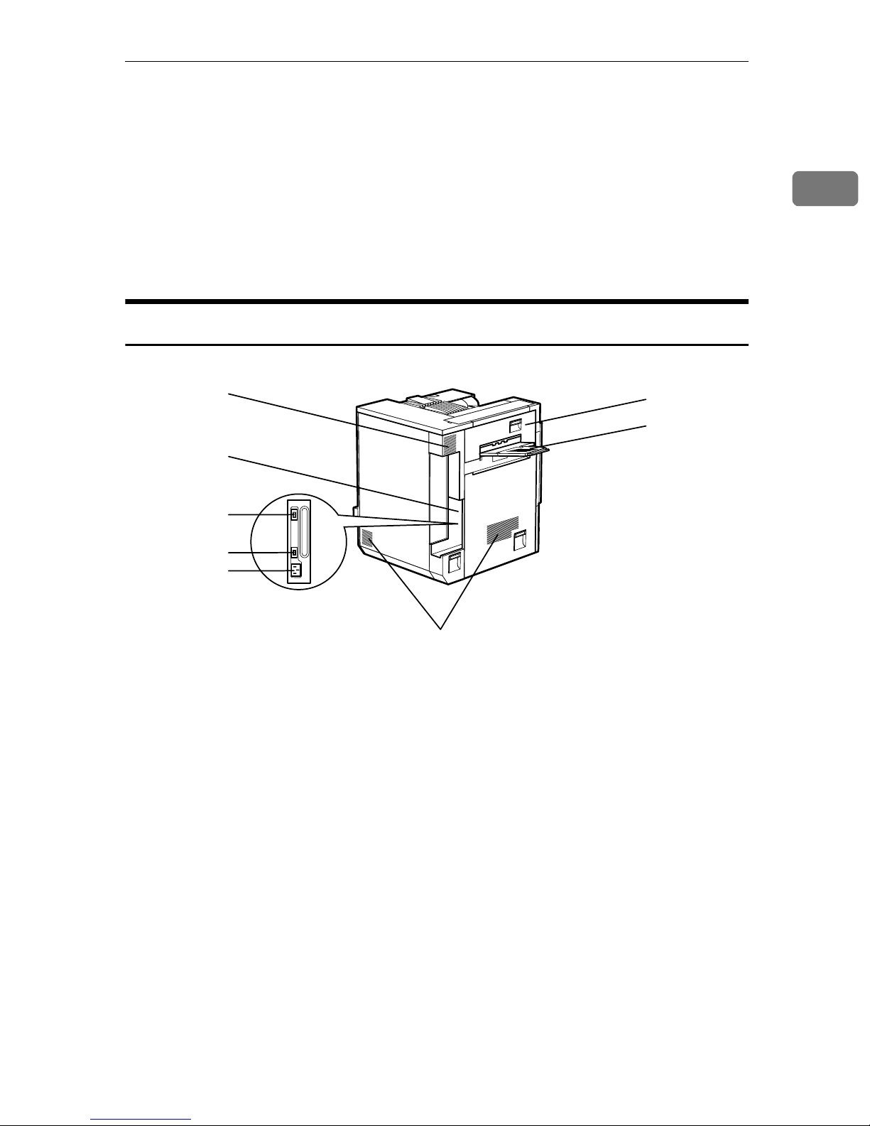
Exterior: Rear View
1
2
15. Ventilator
This hole helps to keep components inside the printer from overheating. Do not
block or obstruct the opening. A malfunction may occur due to overheating.
1
16. Right Cover
Open this cover to remove misfed paper.
6
7
3
4
5
1. Ventilator and Dustproof Filter
This hole helps to keep components inside the printer from overheating. Do not
block or obstruct the ventilator. A malfunction may occur due to overheating.
Remove the ventilator to replace the internal dustproof filter.
2. Connector
Connect the main power cable, cables
from options, etc. to the appropriate port.
3. Duplex Unit Port
Connect the cable for the Duplex Reversal Unit to this port.
4. 4-bin Mailbox/2 Tray Finisher
Port
Connect the cable for the 4-bin Mailbox
or the 2 Tray Finisher to this port.
8
5. Power Port
Connect the power cable to this port and
the other cable end to the wall outlet.
6. Upper Left Cover
Open this cover to remove misfed paper
or when replacing the Fusing Unit.
7. External Tray
Printed output is stacked here with the
print side up.
8. Ventilators
These holes help to keep components inside the printer from overheating. Do not
block or obstruct the ventilators. A malfunction may occur due to overheating.
3
Page 12
Getting Started
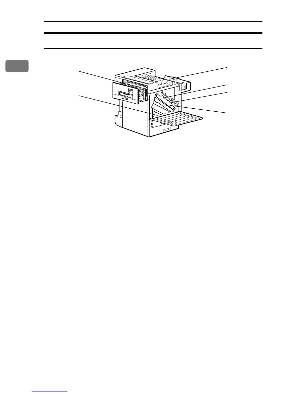
Inside
1
1
2
3
1. Fusing Unit
Fuses the image on paper.
When "Replace Fusing Unit (Type C)" ap-
pears on the panel display, replace this
unit.
2. Fuser Oil Unit
Attach to the Fusing Unit.
When "Replace Fuser Oil Unit (TypeG)"
appears on the panel display, replace this
unit.
3. Waste Toner Bottle
Collects toner that is wasted during
printing.
When "Replace Waste Toner (Type E)"
appears on the panel display, replace
with a new waste toner bottle.
4. Toner Cartridge
Loads from the printer rear in the order
of magenta (M), cyan (C), yellow (Y), and
black (K).
When "Add Toner: color" appears on the
panel display, replace the appropriate
toner cartridge.
4
5
6
7
5. Photoconductor Unit
The printer comes with one black Photoconductor Unit and three color (yellow,
cyan, magenta) Photoconductor Units.
When "Replace Color PCU (Type A)" appears on the panel display, replace the
three color Photoconductor Units.
When "Replace Black PCU (Type F)" appears on the panel display, replace the
black Photoconductor Unit.
6. Development Unit
The printer comes with one black Development Unit and three color (yellow, cyan, magenta) Development Units.
When "Replace Color Dev. Unit(TypeB)"
appears on the panel display, replace the
three color Development Units.
When "Replace Black Dev. Unit(TypeD)"
appears on the panel display, replace the
black Development Unit.
7. Inner Cover
Open this cover when replacing the Photoconductor Unit or Development Unit.
4
Page 13

Operation Panel
Guide to the Printer
1
On Line Menu
Job Reset
Form Feed
Power Error Data In
1. Panel display
Shows the current status of the printer
and error messages.
{{{{Job Reset}}}} key
2.
When the printer is online, press this key
to cancel any ongoing print job.
3. {
{On Line}}}} key
{{
Indicates whether the printer is online or
offline.
Press this key to switch between online
and offline.
When the lamp is lit, the printer is online,
enabling data reception from the host
computer.
When the lamp is off, the printer is offline, disabling data reception from the
host computer.
Press this key to return to the ready condition.
4. {
{Form Feed}}}} key
{{
When the printer is offline, press this key
to print all the data left in the printer's input buffer.
You can use this to force the printer to
print the data received in the online status when the paper size or type does not
match with the actual set size or type.
Escape
#Enter
5. {
{Menu}}}} key
{{
Press this key to make and check the current printer settings.
6. Power indicator
Power indicator is on while the power
switch is on. Power indicator is off when
the power is turned off or while the printer is in Energy Saver mode.
7. Error indicator
Lights up whenever any printer error occurs. However, turns off in the Energy
Saver mode.
8. Data In indicator
Blinks while the printer is receiving data
from a computer. Data In indicator is on
if there is data to be printed.
9. {
{Escape}}}} key
{{
Press this key to return to the previous
condition on the panel display.
10. {
{Enter}}}} key
{{
Press this key to execute menu items selected on the panel display.
11. {
Use these keys to increase or decrease
values on the panel display when making
settings. Keep pressing the key to quicken scrolling, and increase or decrease values on the panel display in units of 10.
}, {{{{TTTT}}}} Keys
{{{UUUU}}}
5
Page 14

1
Getting Started
6
Page 15

2. Setting Up
R
R
Where to Put the Printer
The printer's location should be carefully chosen because environmental conditions greatly affect its performance.
WARNING:
• Confirm that the wall outlet is near the machine and freely accessible, so that in the event of an emergency, it can be easily unplugged.
• Only connect the machine to the power source described on this
sheet.
• Avoid multi-wiring.
• Do not damage, break or make any modifications to the power ca-
ble. Do not place heavy objects on it, pull it hard or bend it more
than necessary. These actions could damage the cable. A frayed or
damaged cable might cause an electrical and fire hazard.
CAUTION:
• Do not handle the plug with wet hands. Doing this might cause an electrical shock.
• Keep the machine in an area that is within optimum environmental conditions. Operating the machine in an environment that is outside the recommended ranges of humidity and temperature can cause an electrical
or fire hazard. Keep the area around the socket free of dust. Accumulated dust can become an electrical or fire hazard.
• Place the machine on a strong and level surface. Otherwise, the machine might fall and injure someone.
• If you use the machine in a confined space, confirm there is a continuous
air turnover.
7
Page 16
Setting Up
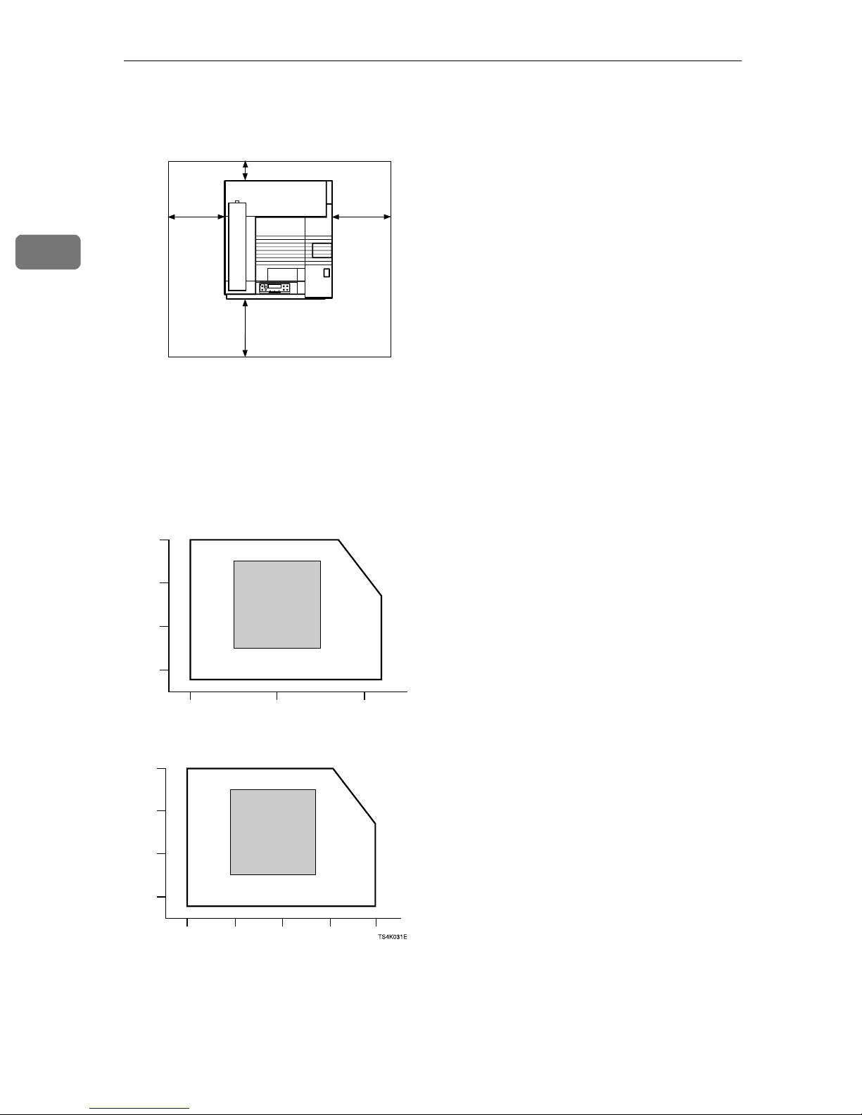
❖❖❖❖ Space Required for Installation
Leave enough space around the printer. This space is necessary to operate the
printer. The recommended (or minimum) space requirements are as follows:
B
2
A
D
C
ZDJX005J
A: 46 cm (19 inch) or more
B: 10 cm (4 inch) or more
C: 55 cm (22 inch) or more
D: 70 cm (28 inch) or more
❖❖❖❖ Optimum Environmental Conditions
Possible and recommended temperature and humidity ranges are as follows:
%RH
80
60
40
15ºC
70%
15ºC
30%
27ºC 80%10ºC 80%
25ºC
70%
25ºC
30%
32
54%
ºC
10ºC 15%
20
10 20 30
%RH
50°F 80%
80
60
40
20
59°F
70%
59°F
30%
50°F 15%
50 80 90
60 70
32ºC 15%
ºC
ZDJX006J
80.6°F 80%
77°F
70%
89.6°F
54%
77°F
30%
89.6°F 15%
°F
• White area: Possible operation Range
• Gray area: Recommended Range
8
Page 17

Where to Put the Printer
Note
❒ The machine must be level within 5 mm, 0.2" both front to rear and left to
right.
❒ To avoid possible build-up of ozone, locate this machine in a large well
ventilated room that has an air turnover of more than 30 m
❒ When you use this machine for a long time in a confined space without
good ventilation, you may notice an odd smell. To keep the workplace
comfortable, we recommend that you keep it well ventilated.
3
/hr/person.
❖❖❖❖ Environments to Avoid
Important
❒ Locations exposed to direct sunlight or strong light
❒ Dusty areas
❒ Areas with corrosive gases
❒ Areas excessively cold, hot, or humid
❒ Locations near an air conditioner or humidifier
❒ Locations near other electronic equipment
❒ Locations where the printer might be subjected to frequent strong vibra-
tion
❖❖❖❖ Power Source
Connect the power cable to a power source with the following specifications:
• 120 V, 60 Hz, 10 A or more
2
9
Page 18
2
Setting Up
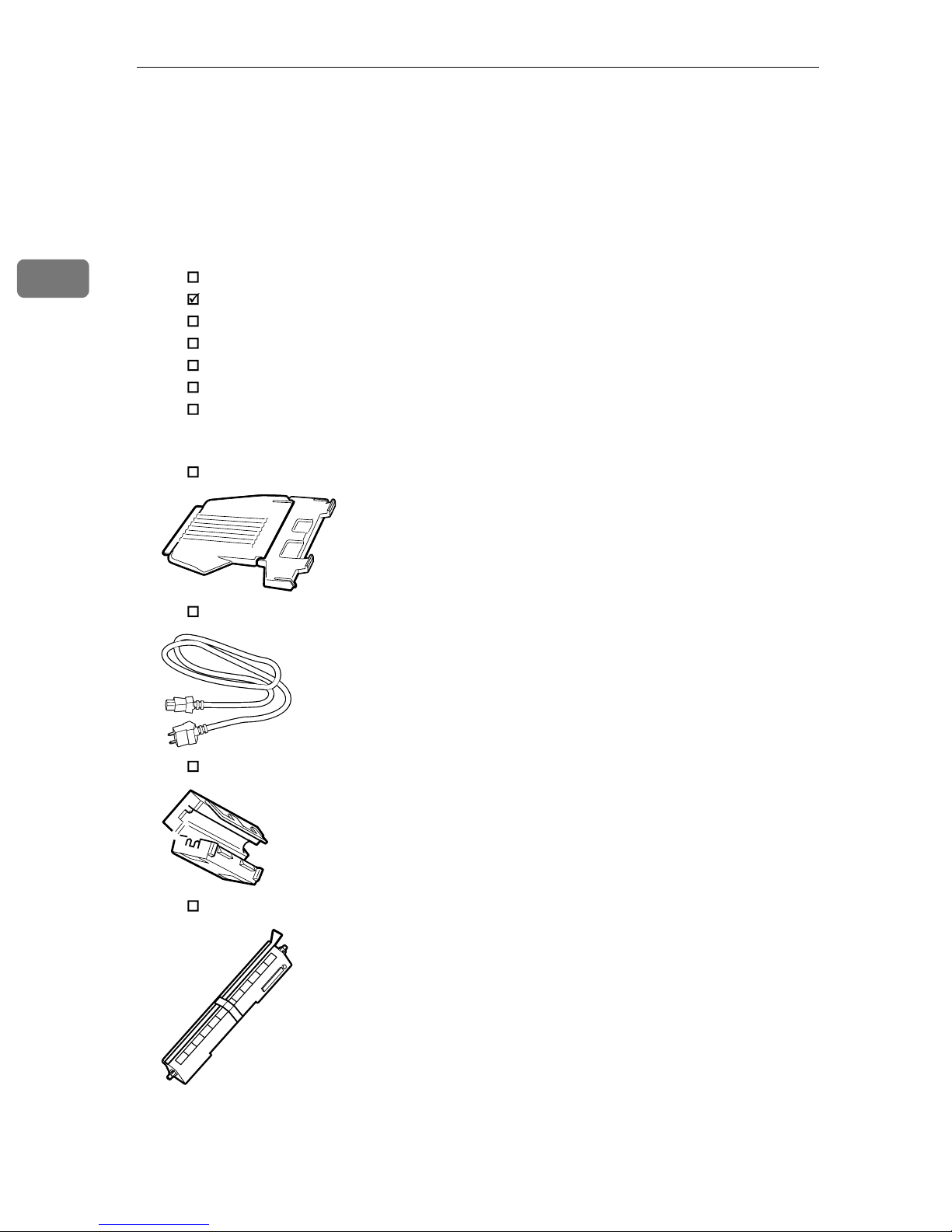
Checking the Contents of the Box
Check the contents of the box for the following items.
A
For missing items, contact your sales or service representative.
❖❖❖❖ Manuals and CD-ROMs
Description form
Setup Guide (This manual)
Maintenance Guide 1
Administrator Reference 1
Printer Client Reference 1
CD-ROM "Printer Driver and Utilities"
CD-ROM "Operating Instructions"
❖❖❖❖ Parts
External Tray
Power Cable
Ferrite Core
Fuser Oil Unit
10
Page 19
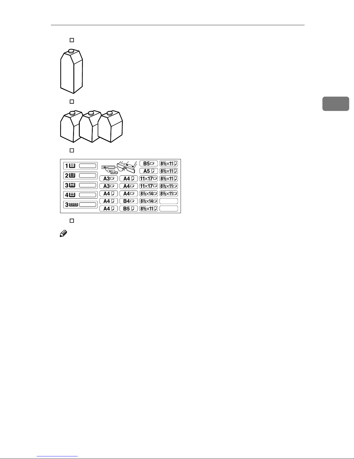
Black Toner Cartridge (K)
Checking the Contents of the Box
Magenta (M), Cyan (C), Yellow (Y) Toner Cartridges
Paper Feed Unit Labels
Additional Documentations
Note
❒ This package does not include an interface cable. Please purchase one for
use with your host computer. See “Appendix” in Administrator Reference
2.
2
11
Page 20
Setting Up
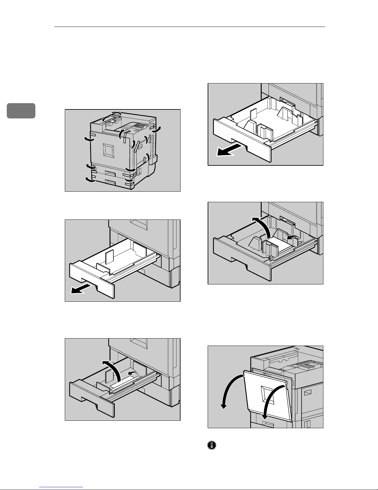
Unpacking the Printer
2
Remove the adhesive tape on the
A
printer body. Remove the cardboard that is taped to the Standard Tray.
Open Tray 1.
B
ZDJH001J
Open Tray 2.
E
Remove the adhesive tape and
F
sheet of paper.
ZDJH005J
12
Remove the adhesive tape and
C
sheet of paper.
Close Tray 1 slowly.
D
ZDJH003J
ZDJH004J
Close Tray 2 slowly.
G
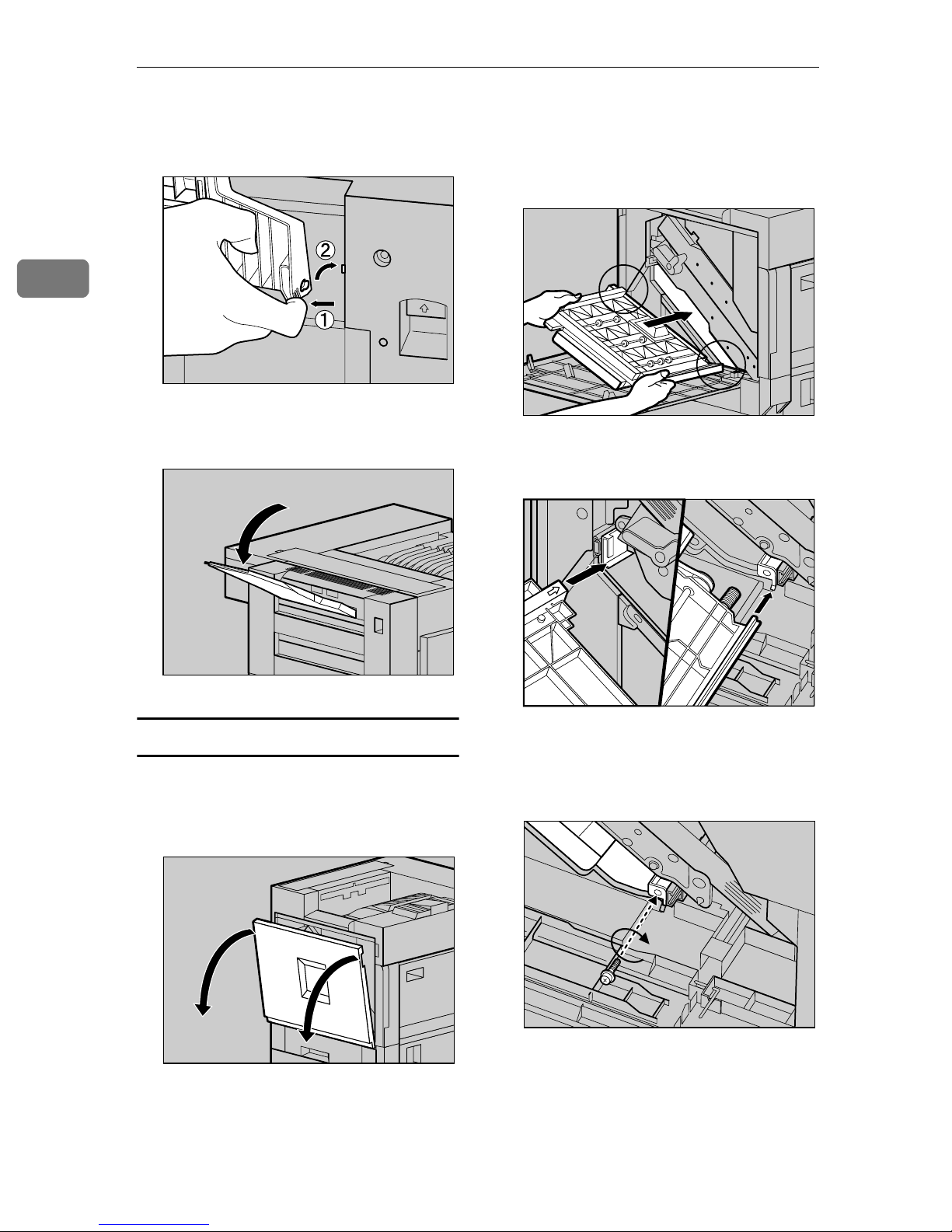
Open the front cover slowly by
H
pulling down from the two areas
on the left and right.
Important
❒ Do not place objects on the opened
front cover.
ZDJH006J
ZDJH007J
Page 21
Unpacking the Printer
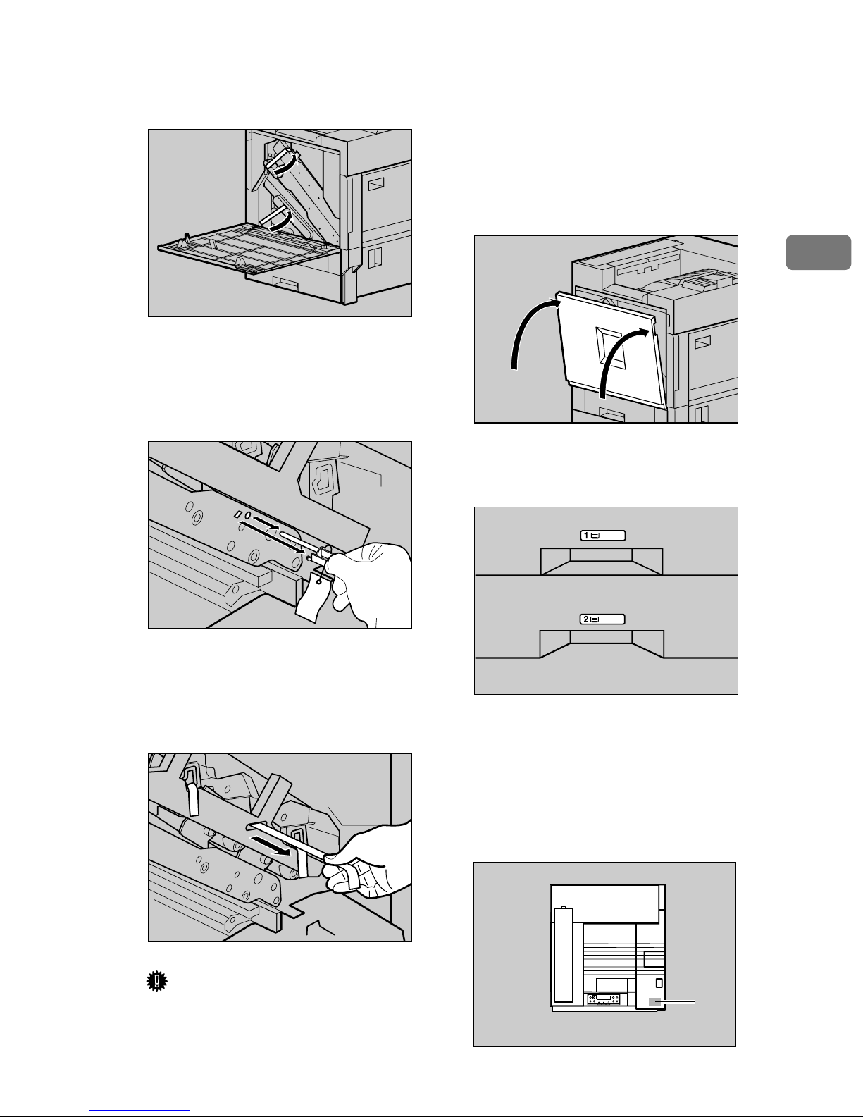
Remove the adhesive tape.
I
Remove the securing pin, as
J
shown in the illustration, from
the Transfer Unit. Pinch it, and
then pull it out.
ZDJH008J
❒ The removed tape is dirty. Be
careful not to let it touch your
hands or clothes.
Close the front cover slowly by
L
pushing the two areas on the left
and right.
Put labels "1" and "2" on the front
M
of the paper trays.
2
ZDJH041J
Pull out the four pieces of tapes
K
coming out from the Development Unit slowly, in a level manner.
Important
❒ Be sure to pull out all four piec-
es of tapes to avoid printer malfunction during operation.
ZDJX450J
ZDJH702J
A sticker, stating that paper for an
N
ink-jet printer cannot be used with
this printer, is supplied. Please attach the sticker to the bottom right
corner of the top of the printer [A]
so that sticker is easy to see.
ZDJP129J
A
ZDJX005E
13
Page 22
Setting Up
Installing the Fuser Oil Unit
2
Install the Fuser Oil Unit to the Fusing
Unit.
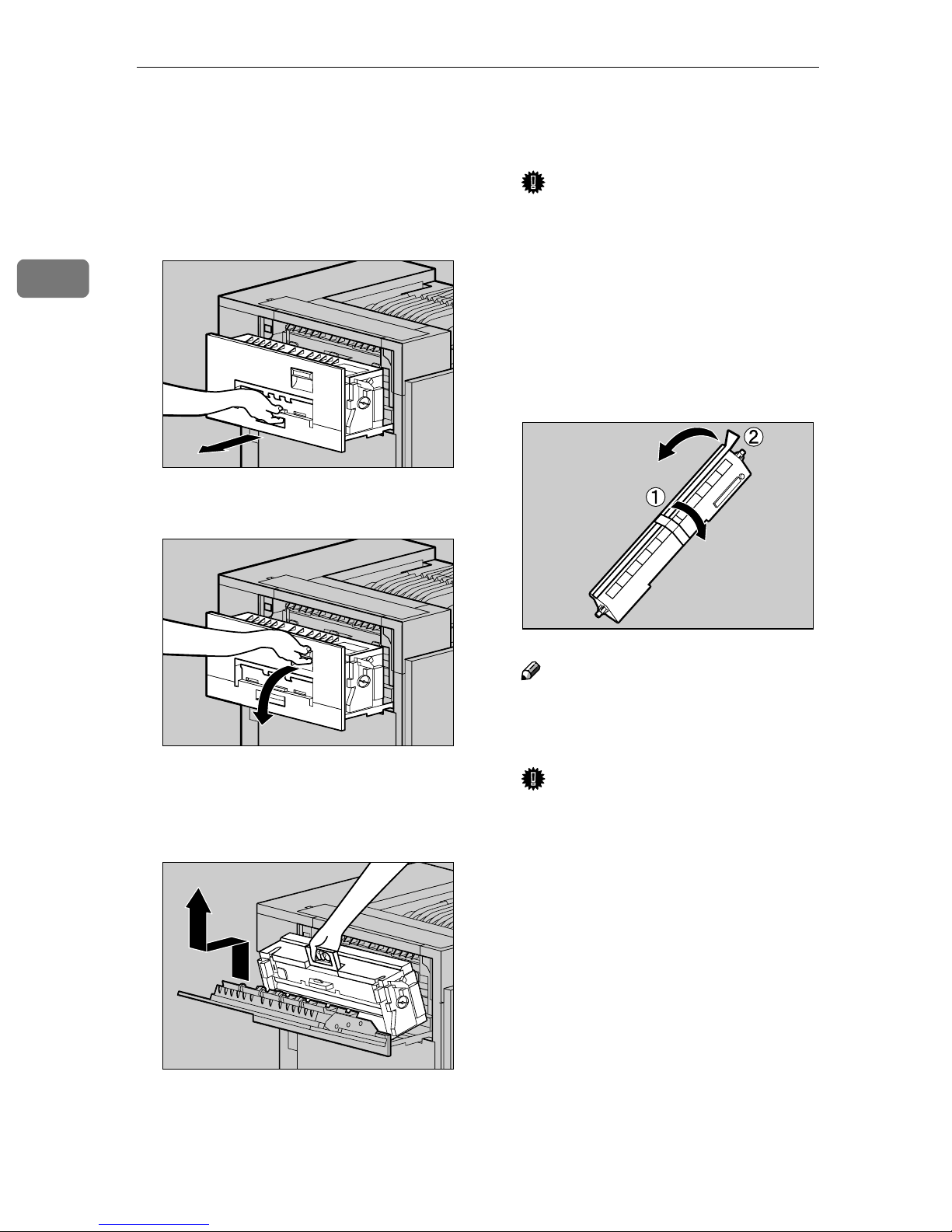
Pull out the left cover slowly.
A
ZDJH047J
Open the upper left cover.
B
Important
❒ Do not touch any areas other
than the handle.
Put the removed Fusing Unit in a
D
stable and level place.
Take out the Fuser Oil Unit from
E
the bag, and remove seal (AAAA), and
then seal (BBBB) as shown in the illustration.
Holding the green handle, pull up
C
the Fusing Unit slowly in the direction as shown in the illustration.
ZDJH048J
ZDJH049J
ZDJH053J
Note
❒ Be sure to remove seal (A), and
then pull it out in a level manner.
Important
❒ Be sure to remove the seals to
avoid printer malfunction.
❒ Be sure to remove seal (A) first,
and then remove seal (B) to
avoid an oil leak.
❒ There is oil on the removed
seals. Be careful not to let them
come in contact with your
clothes.
❒ Be sure to put the Fusing Oil in
a stable and level place.
14
Page 23

Installing the Fuser Oil Unit
Hold the Fuser Oil Unit in the
F
manner shown in the illustration.
Match (UUUU) on the front of the Fuser Oil Unit and (TTTT) on the Fusing
Unit at three places. While pushing the green lever on the left side
of the Fusing Unit (AAAA), insert the
left and right protrusions of the
Fuser Oil Unit into the white
holders of the Fusing Unit (BBBB),
and then move the Fuser Oil Unit
in the direction shown by the arrow (CCCC) to attach the Fuser Oil
Unit to the Fusing Unit.
Note
❒ Confirm that the Fuser Oil Unit
is facing the inside of the printer.
Important
❒ Confirm that the Fusing Unit is
in appropriate position.
Close the upper left cover (AAAA) and
H
push the handle (BBBB) slowly to the
back until it clicks.
2
Important
❒ Be careful not to get oil on the
metal part of the left side of the
Fuser Oil Unit.
Holding the green handle with
G
one hand, use your other hand to
push the front area of the handle
to a slight slant, and then push the
Fusing Unit slowly to the back.
ZDJH054E
Attach the External Tray to the
I
printer. Insert the hooks of the External Tray into the printer slits,
and then lower it toward you.
ZDJH051J
ZDJH010J
Confirm that the Fusing Unit is set
to the printer vertically.
ZDJH050E
15
Page 24
Setting Up
R
Installing Options
CAUTION:
• Before installing options, the machine should be turned off and unplugged
for at least an hour. Components inside the machine become very hot, and
can cause a burn if touched.
2
• Before moving the machine, unplug the power cable from the outlet. If the
cable is unplugged abruptly, it could become damaged. Damaged plugs or
cables can cause an electrical or fire hazard.
• When lifting the machine, use the grips on both sides. The machine could
break or cause an injury if dropped.
By installing options, you can improve the printer performance and have an expanded variety of features to use. For details on each option, see Administrator
Reference 2.
When installing multiple options on the printer, we recommend the following
order of installation.
Important
❒ Rating voltage of the connector for options: Max. DC 24 V.
❖❖❖❖ Flow of Option Installation
A
Install the 500, 1000-sheet Paper
Feed Unit, or 2000-sheet Large
Capacity Tray.
(PAPER FEED UNIT Type
3800C, Paper Bank PS 470)
Install the Paper Feed Unit to the bottom of the printer.
You can choose to install the PAPER FEED UNIT Type
3800C (500 × 1), Type 3800C (500 × 2) or Paper Bank PS470.
If you install the Paper Bank PS470, you can load up to 3,100
sheets of paper at once.
T
B
Install the SDRAM Module.
(Memory Unit TypeB)
T
C
Install the 1394 Interface Unit.
(1394 Interface Unit Type1045)
T
D
Install the User Account Enhance
Unit Type B.
T
16
Attach the module to the SDRAM module slot of the Controller Board.
There are three types of Memory Unit TypeB, 64MB, 128MB,
256MB.
Attach the 1394 Interface Unit Type 1045 to the 1394 I/F slot
of the Controller Board.
The 1394 Interface Unit requires optional Memory Unit at
least 64 MB (Total memory size 128 MB or more).
Attach the module to the User Account Enhance Unit slot of
the Controller Board.
Page 25

Installing Options
E
Install the Printer Hard Disk.
(Printer Hard Disk Type 3800C)
T
F
Install the Duplex Unit.
(Duplex Unit Type 3800C)
T
G
Install the 2 Tray Finisher.
(SR770)
T
H
Install the 4-bin Mailbox.
(Mail Bin Type 3800C)
Attach the Printer Hard Disk Type 3800C to the Controller
Board.
Attach the Duplex Reversal Unit to the left side of the printer, and the Duplex Feed Unit inside the printer.
2
Attach the SR770 to the left side of the printer.
You cannot install the SR770 unless both the Paper Feed
Unit and Duplex Unit options are installed.
If you choose to install the 4-bin Mailbox, you cannot install
the SR770.
The 2 Tray Finisher requires the optional Printer Hard Disk
or the optional Memory Unit at least 128 MB (Total memory
size 160 MB or more).
Remove the upper cover to install Mail Bin Type 3800C.
If you choose to install the 2 Tray Finisher, you cannot install the 4-bin Mailbox.
Install options in the positions as shown in the illustration.
17
Page 26

2
Setting Up
❖❖❖❖ Exterior
1. PAPER FEED UNIT Type 3800C
(500 ×××× 1)
Loads up to 500 sheets (500 sheets × 1 column) of paper.
⇒
P.21 “Installing the PAPER FEED UNIT
Type 3800C (500 x 1)”
2. PAPER FEED UNIT Type 3800C
(500 ×××× 2)
Loads up to 1,000 sheets (500 sheets × 2
columns) of paper.
⇒
P.24 “Installing the PAPER FEED UNIT
Type 3800C (500 x 2)”
3. Paper Bank PS470 (2000-sheet
Large Capacity Tray)
Loads up to 2,000 sheets (2,000 sheets × 1
column) of paper.
⇒
P.26 “Installing the Paper Bank PS470
(2000-sheet Large Capacity Tray)”
ZDJP001J
4. SR770 (2 Tray Finisher)
Performs Job Separation, staples and
punches holes. Install the Finisher on the
left side of the printer.
⇒
P.47 “Installing the SR770 (2 Tray Fin-
isher)”
5. Mail Bin Type 3800C (4-bin Mail-
box)
Sorts printed documents from multiple
users. Attach the Mailbox to the top of the
printer.
⇒
P.54 “Installing the Mail Bin Type 3800C
(4-bin Mailbox)”
6. Duplex Reversal Unit
Flips over the paper during duplex printing. Install the unit on the left side of the
printer.
⇒
P.44 “Installing the Duplex Reversal
Unit”
18
Page 27

Installing Options
7. Duplex Feed Unit
Transports the paper during duplex printing. Install the unit inside the printer.
⇒ P.44 “Installing the Duplex Reversal
Unit”
Important
❒ You cannot install the 2 Tray Finisher unless both the Paper Feed Unit and
Duplex Unit options are installed.
❒ You cannot install the 2 Tray Finisher unless at least the 128 MB SDRAM
Module is installed, or the Printer Hard Disk is installed.
❒ You cannot install both the 2 Tray Finisher and 4-bin Mailbox at the same
time.
❖❖❖❖ Interior
1
2
2
3
4
1. Memory Unit Type B (SDRAM
Module)
Attach 64MB, 128MB, or 256MB RAM
into the slot of the Controller Board.
⇒ P.29 “Installing the Memory Unit Type B
(SDRAM Module)”
2. 1394 Interface Unit Type1045
⇒ P.31 “Installing the 1394 Interface Unit
Type1045”
ZDJP002J
3.
User Account Enhance Unit Type B
⇒ P.34 “Installing the User Account En-
hance Unit TypeB”
4. Printer Hard Disk Type 3800C
Attach Printer Hard Disk to the Controller Board.
⇒ P.37 “Installing the Printer Hard Disk
Type 3800C”
Important
❒ You cannot install the 1394 Interface Unit Type1045 unless at least 64MB
SDRAM Module is installed.
19
Page 28

2
R
Setting Up
How to Use the Screwdriver
The exclusive screwdriver used for attaching options is attached to the inside of
the front cover. By pushing the screw top into the screwdriver, you can work
without having to worry about dropping the screw.
ZDJP003J
Note
❒ After using the screwdriver, return it to its original position on the inside of
the front cover.
Installing the Paper Feed Unit
Preparation
If you want to use the optional Duplex Unit, 2 Tray Finisher or 4-bin
Mailbox at the same time, install
the optional Paper Feed Unit first,
and then install these options.
If you have already installed the
optional Duplex Unit, 2 Tray Finisher and 4-bin Mailbox, remove
all these options before installing
the optional Paper Feed Unit.
Important
❒ Before installation, check the ori-
entation of the Paper Feed Unit or
2000-sheet Large Capacity Tray
you want to place.
❒ Four persons are needed to install
the Paper Feed Unit. Start the installation work after all four persons are ready.
CAUTION:
• When moving the machine, each
person should hold the handle,
where two are located on opposite sides, and lift slowly. Lifting it
carelessly or dropping it may
cause an injury.
Note
❒ The printer weights approximately
77 kg (170 lbs).
❒ When installing multiple options,
install the Paper Feed Unit first.
20
Page 29

Installing the PAPER FEED UNIT Type
R
3800C (500 x 1)
Preparation
If you want to use the optional Duplex Unit, 2 Tray Finisher or 4-bin
Mailbox at the same time, install
the optional Paper Feed Unit first,
and then install these options.
Remove the adhesive tape.
B
Installing Options
2
If you have already installed the
optional Duplex Unit, 2 Tray Finisher and 4-bin Mailbox, remove
all these options before installing
the optional Paper Feed Unit.
Important
❒ Before installation, check the ori-
entation of the Paper Feed Unit
you want to place.
❒ When installing multiple options,
install the Paper Feed Unit first.
CAUTION:
• When moving the Paper Feed
Unit, hold the bottom of both
sides, and lift slowly. Lifting it
carelessly or dropping it may
cause an injury.
Note
❒ The 500-sheet Paper Feed Unit
weights approximately 18kg (39.7
lbs).
Adjust the four corners of the
C
printer to those of the 500-sheet
Paper Feed Unit, and then lower
the printer slowly into place.
Important
❒ Four persons should hold the
handles, located on two sides of
the printer, to move it.
ZDJP004J
ZDJP006J
Turn off the power switch and
A
unplug the power cable.
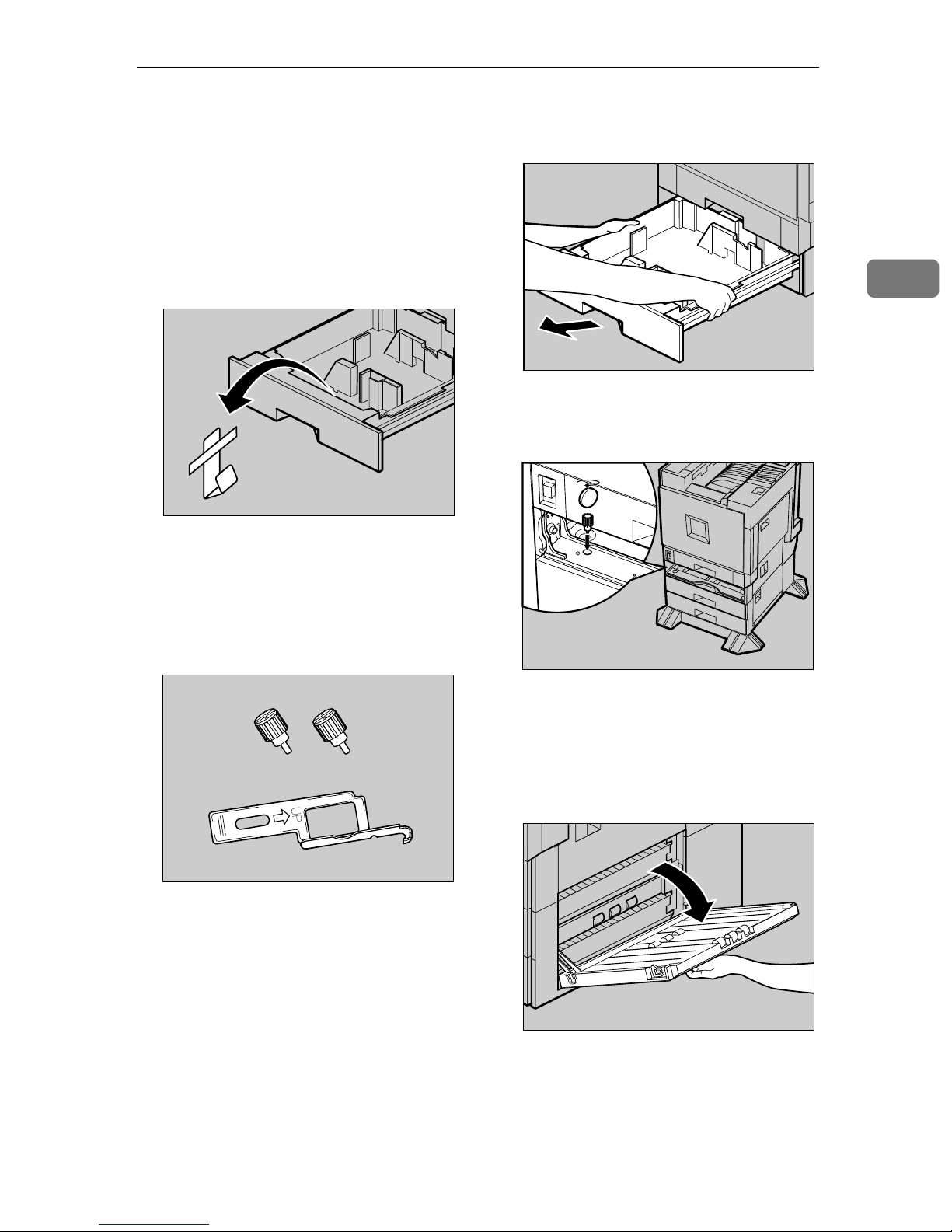
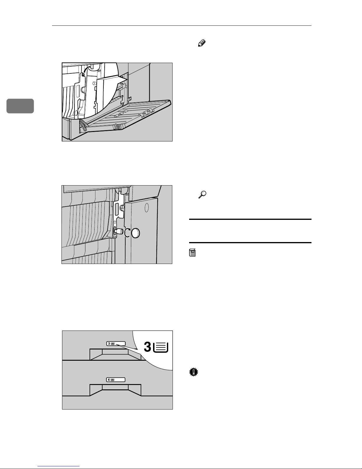
Open the tray of the 500-sheet Pa-
D
per Feed Unit.
A Remove the adhesive tape and
sheet of paper.
ZDJP007J
21
Page 30

Setting Up
2
B Remove the adhesive tape and
the corrugated paper inside the
tray as shown in the illustration.
Take out the packaged items,
E
making sure there are two thumb
screws and one mounting bracket. Close the tray of the 500-sheet
Paper Feed Unit tightly.
ZDJX801J
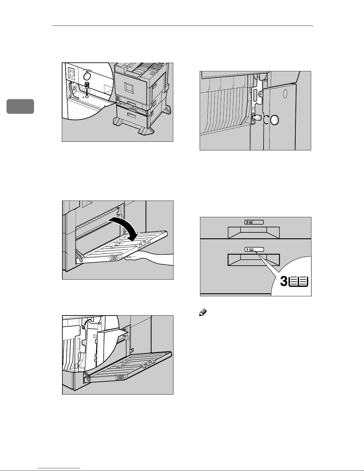
Fasten one thumb screw. Use a
G
coin to fasten it tightly.
Slide Tray 2 back into the printer
H
slowly until it stops.
Open the right cover of the 500-
I
sheet Paper Feed Unit.
ZDJP009J
Pull out Tray 2 slowly while lift-
F
ing it up a little.
ZDJP005J
ZDJP008J
Hook the mounting bracket to the
J
hole as shown in the illustration.
ZDJP010J
ZDJP011J
22
Page 31

Installing Options
Fasten the bracket with the other
K
thumb screw. Use a coin to fasten
it tightly.
Close the right cover of the 500-
L
sheet Paper Feed Unit.
Stick label "3" above the handle
M
on the front of the 500-sheet Paper
Feed Unit.
ZDJP012J
❒ If the Paper Feed Unit is not in-
stalled properly, reinstall from
step
properly even after reinstallation, contact your sales or service representative.
Reference
. If you cannot install it
A
⇒ P.68 “Test Printing”.
2
Note
❒ After finishing all installation
for printing, you can check
whether the 500-sheet Paper
Feed Unit is installed properly.
Print the Configuration Page
from the "List/Test Print"
menu. If it is installed properly,
you will see "Paper Feed Unit
(Tray 3)" under the "Options"
list.
ZDJP126J
23
Page 32

2
R
Setting Up
Installing the PAPER FEED UNIT Type
3800C (500 x 2)
Preparation
If you want to use the optional Duplex Unit, 2 Tray Finisher or 4-bin
Mailbox at the same time, install
the optional Paper Feed Unit first,
and then install these options.
Remove the adhesive tape.
B
If you have already installed the
optional Duplex Unit, 2 Tray Finisher and 4-bin Mailbox, remove
all these options before installing
the optional Paper Feed Unit.
Important
❒ Before installation, check the ori-
entation of the Paper Feed Unit
you want to place.
❒ When installing multiple options,
install the Paper Feed Unit first.
CAUTION:
• When moving the Paper Feed
Unit, hold the bottom of both
sides, and lift slowly. Lifting it
carelessly or dropping it may
cause an injury.
Note
❒ The 1000-sheet Paper Feed Unit
weights approximately 25kg (55.2
lbs).
Adjust the four corners of the
C
printer to those of the 1000-sheet
Paper Feed Unit, and then lower
the printer slowly into place.
Important
❒ Four persons should hold the
handles, located on two sides of
the printer, to move it.
ZDJP013J
ZDJP014J
Turn off the power switch and
A
unplug the power cable.
24
ZDJP007J
Page 33
Installing Options
Open the tray of the 1000-sheet
D
Paper Feed Unit.
A Remove the adhesive tape and
sheet of paper.
B Remove the adhesive tape and
the corrugated paper inside the
tray as shown in the illustration.
Take out the packaged items,
E
making sure there are two thumb
screws and one mounting bracket. Close the tray of the 1000-sheet
Paper Feed Unit tightly.
ZDJX801J
Pull out Tray 2 slowly while lift-
F
ing it up a little.
Fasten one thumb screw. Use a
G
coin to fasten it tightly.
2
ZDJP008J
ZDJP015J
ZDJP005J
Slide Tray 2 back into the printer
H
slowly until it stops.
Open the right cover of the 1000-
I
sheet Paper Feed Unit.
ZDJP016J
25
Page 34
Setting Up
2
Hook the mounting bracket to the
J
hole as shown in the illustration.
Fasten the bracket with the other
K
thumb screw. Use a coin to fasten
it tightly.
ZDJP017J
Note
❒ After finishing all installation
for printing, you can check
whether the 1000-sheet Paper
Feed Unit is installed properly.
Print the Configuration Page
from the "List/Test Print"
menu. If it is installed properly,
you will see "Paper Feed Unit
(Tray 3 & Tray 4)" under the
"Options" list.
❒ If the Paper Feed Unit is not in-
stalled properly, reinstall from
step
properly even after reinstallation, contact your sales or service representative.
Reference
. If you cannot install it
A
⇒ P.68 “Test Printing”.
Close the right cover of the 1000-
L
sheet Paper Feed Unit.
Stick labels "3" and "4" above the
M
handles on the front of the 1000sheet Paper Feed Unit.
ZDJP018J
Installing the Paper Bank PS470 (2000sheet Large Capacity Tray)
Preparation
If you want to use the optional Duplex Unit, 2 Tray Finisher or 4-bin
Mailbox at the same time, install
the optional 2000-sheet Large Capacity Tray first, and then install
these options.
If you have already installed the
optional Duplex Unit, 2 Tray Finisher and 4-bin Mailbox, remove
all these options before installing
the optional 2000-sheet Large Capacity Tray.
Important
❒ Before installation, check the ori-
entation of the 2000-sheet Large
Capacity Tray you want to place.
26
ZDJP127J
❒ When installing multiple options,
install the Paper Feed Unit first.
Page 35

Installing Options
R
CAUTION:
• When moving the Paper Feed
Unit, hold the bottom of both
sides, and lift slowly. Lifting it
carelessly or dropping it may
cause an injury.
Note
❒ The 2000-sheet Large Capacity
Tray weights approximately 25kg
(55.2 lbs).
Turn off the power switch and
A
unplug the power cable.
Remove the adhesive tape.
B
Important
❒ Four persons should hold the
handles, located on two sides of
the printer, to move it.
Take out the packaged items,
D
making sure there are two thumb
screws and one mounting bracket. Close the tray of the 2000-sheet
Large Capacity Tray tightly.
2
ZDJP007J
Adjust the four corners of the
C
printer to those of the 2000-sheet
Large Capacity Tray, and then
lower the printer slowly into
place.
ZDJP019J
ZDJP020J
Pull out Tray 2 slowly while lift-
E
ing it up a little.
ZDJP005J
ZDJP008J
27
Page 36
Setting Up
2
Fasten one thumb screw. Use a
F
coin to fasten it tightly.
Slide Tray 2 back into the printer
G
slowly until it stops.
Open the right cover of the 2000-
H
sheet Large Capacity Tray.
ZDJP021J
Fasten the bracket with the other
J
thumb screw. Use a coin to fasten
it tightly.
Close the right cover of the 2000-
K
sheet Large Capacity Tray.
Stick label "3" above the handle
L
on the front of the 2000-sheet
Large Capacity Tray.
ZDJP024J
Hook the mounting bracket to the
I
hole as shown in the illustration.
ZDJP022J
ZDJP023J
ZDJP128J
Note
❒ After finishing all installation
for printing, you can check
whether the 2000-sheet Large
Capacity Tray is installed properly. Print the Configuration
Page from the "List/Test Print"
menu. If it is installed properly,
you will see "LCT Tandem
Bank" under the "Options" list.
28
Page 37
Installing Options
❒ If the Paper Feed Unit is not in-
stalled properly, reinstall from
step
properly even after reinstallation, contact your sales or service representative.
Reference
⇒ P.68 “Test Printing”.
. If you cannot install it
A
Installing the Memory Unit
Type B (SDRAM Module)
Important
❒ Be sure to touch a metal object be-
fore touching the Memory Unit to
discharge static electricity. Even a
small amount of static electricity
can damage the unit.
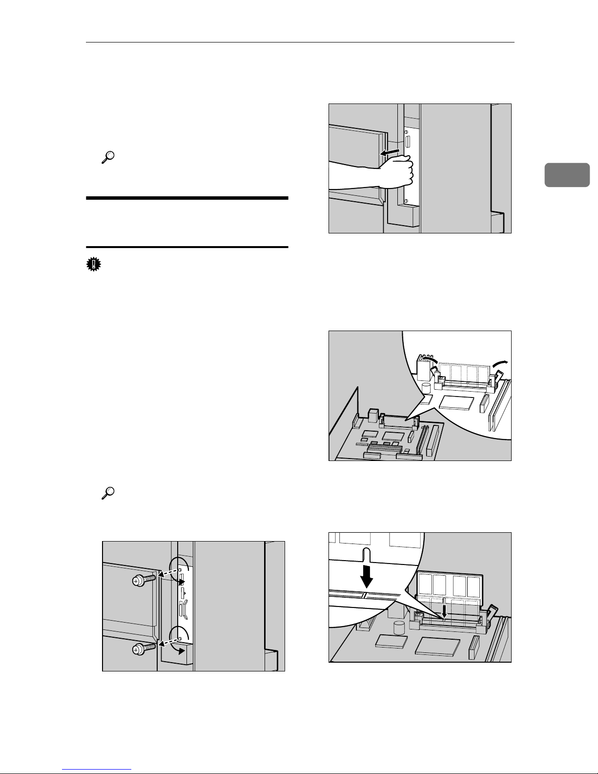
Holding the handle, pull out the
C
Controller Board slowly.
Put the Controller Board in a flat
D
place.
Open the locks on the left and
E
right sides of the open slot.
2
ZDJP025J
❒ Do not subject the SDRAM Mod-
ule to physical shocks.
Turn off the power switch and
A
unplug the power cable.
Remove two screws that are fas-
B
tening the Controller Board on
the back of the printer using provided screwdriver.
Reference
See P.20 “How to Use the Screw-
driver”.
Adjust the notch of the Memory
F
Unit to the slot and insert vertically.
ZDJP027J
The removed screws will be used
later to fasten the Controller
Board.
ZDJP025J
ZDJP028J
29
Page 38
Setting Up
2
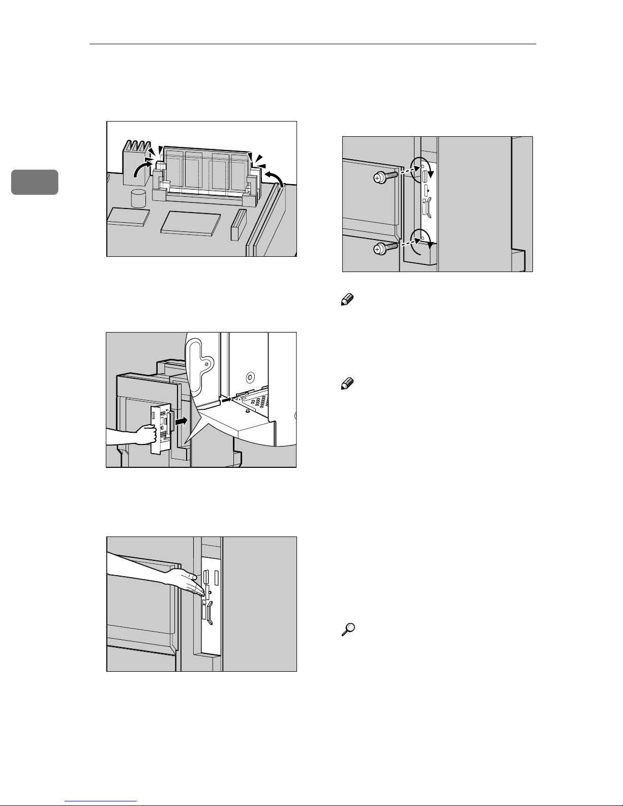
Keep pressing the Memory Unit
G
down until it clicks into the
locked position.
Adjust the Controller Board to the
H
top and bottom rails, and push in
slowly until it stops.
ZDJP029J
Tighten two screws to fasten the
I
Controller Board back into its
original position using provided
screwdriver.
Note
❒ Be sure to return the provided
screwdriver to its original position on the inside of the front
cover.
ZDJP031J
ZDJP030J
Insert the Controller Board firmly
by pushing the left area as shown
in the illustration.
ZDJP801J
Note
❒ After finishing all installation
for printing, you can check
whether the Memory Unit is installed properly. Print the Configuration Page from the "List/
Test Print" menu. If it is installed properly, you will see
the memory capacity for "Total
Memory".
❒ If the Memory Unit is not in-
stalled properly, reinstall from
step
. If you cannot install it
A
properly even after reinstallation, contact your sales or service representative.
Reference
See P.68 “Test Printing”.
30
Page 39

Installing the 1394 Interface
Installing Options
Check the contents of the box.
A
Unit Type1045
Important
❒ Windows 2000 is the only operating
system that can output to a printer
with the 1394 Interface Unit.
❒ Outputting is not possible with Win-
dows 95, 98, or Me. If the "plug and
play" function starts, click [
❒ The 1394 Interface Unit Type1045
requires the optional Memory Unit
at least 64 MB or more.
❒ In Windows 2000, the 1394 Inter-
face Unit can only be used with Service Pack 1 or later. If the Service
Pack is not installed, the connectable number of devices in a 1394
bus is only one, and the client cannot access the 1394 Interface Unit
without using an account that has
the Administrators permission.
Cancel
].
❖❖❖❖ 1394 Interface Unit Type1045
2
❖❖❖❖ Four Screws
❖❖❖❖ Interface Cable (6 pin ×××× 6 pin)
❖❖❖❖ Interface Cable (6 pin ×××× 4 pin)
❒ The 1394 Interface Unit cannot re-
ceive data from more than one PC at
the same time. If it happens, an error
message appears. The printer can accept data sent from other PCs only
after the first print job has finished.
❒ Bidirectional transmissions are not
supported by the 1394 Interface Unit.
❒ Be sure to touch a metal object be-
fore touching the 1394 Interface
Unit to discharge static electricity.
Even a small amount of static electricity can damage the unit.
❒ Do not subject the 1394 Interface
Unit to physical shocks.
❒ Do not loop the 1394 interface cable.
❒ Use the 1394 Interface cable that
comes with 1394 Interface Unit.
Reference
For more information, see the
Manual that comes with the 1394
Interface Unit.
Note
❒ Use the screwdriver attached to
the inside of the front cover of
the machine for two screws.
❒ You will not use the two smaller
screws.
Turn off the power switch and
B
unplug the power cable and interface cable.
31
Page 40
Setting Up
2
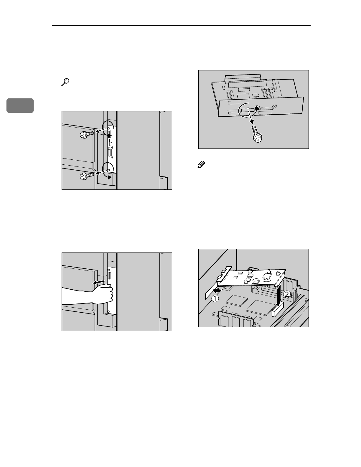
Remove two screws that are fas-
C
tening the Controller Board on
the back of the printer using provided screwdriver.
Reference
See P.20 “How to Use the Screw-
driver”.
The removed screws will be used
later to fasten the Controller
Board.
Holding the handle, pull out the
D
Controller Board slowly.
ZDJP025J
Remove the small cover plate us-
F
ing provided screwdriver as
shown in the illustration.
Note
❒ You will not use the removed
screws.
Install the 1394 Interface Unit on
G
the Controller Board. Insert the
tip of the 1394 Interface Unit into
the attachment area (AAAA), and push
it in the direction of the arrow
(BBBB).
ZDJP122E
Put the Controller Board in a flat
E
place.
32
ZDJP025J
ZDJP120J
Confirm that the 1394 Interface
Unit is connected firmly to the
Controller Board.
Page 41

Installing Options
Tighten two screws to fasten the
H
1394 Interface Unit using provided screwdriver.
Insert the Controller Board into
I
the top and bottom rails, and slide
it in slowly until it stops.
ZDJP123E
Tighten two screws to fasten the
J
Controller Board back into its
original position using provided
screwdriver.
Note
❒ Be sure to return the provided
screwdriver to its original position on the inside of the front
cover.
2
ZDJP803J
ZDJP030J
Insert the Controller Board firmly
by pushing the left area as shown
in the illustration.
ZDJP802J
Note
❒ After finishing all installation
for printing, you can check
whether the 1394 Interface Unit
is installed properly. Print the
Configuration Page from the
"List/Test Print" menu. If it is
installed properly, you will see
"Installed" for "IEEE1394".
❒ If the 1394 Interface Unit is not
installed properly, "Not Installed" is shown. In such a case,
reinstall from step
. If you can-
A
not install it properly even after
reinstallation, contact your sales
or service representative.
Reference
See P.68 “Test Printing”.
33
Page 42

2
R
Setting Up
Check for spare parts. You will
K
not use these spare parts.
Connecting the cable to the 1394
Interface Unit
Connect the interface cable to the
A
1394 interface port.
Installing the User Account
Enhance Unit TypeB
CAUTION:
• Do not place the IC2 lithium battery near or into fire, or it will explode and cause a burn.
• The User Account Enhance Unit
installed on the controller has a
IC2 lithium battery which can explode if replaced incorrectly. Replace the User Account Enhance
Unit only with the indicated one.
Note
❒ Disposal should take place at an
authorized dealer or an appropriate collection site. An IC2 lithium
battery is inside the User Account
Enhance Unit.
Note
❒ Either connector can be used.
❒ If you use a 6 pin × 6 pin inter-
face cable, connect the end with
the ferrite core to the printer.
Connect the other end to the host
B
computer.
ZDJP500J
❒ If you are disposing the Unit, sepa-
rate the IC2 lithium battery from
the board and dispose of them according to local regulations.
Important
❒ Be sure to touch a metal object be-
fore touching the User Account
Enhance Unit to discharge static
electricity. Even a small amount of
static electricity can damage the
unit.
❒ Do not subject the User Account
Enhance Unit to physical shocks.
34
Page 43

Installing Options
Check the contents of the box.
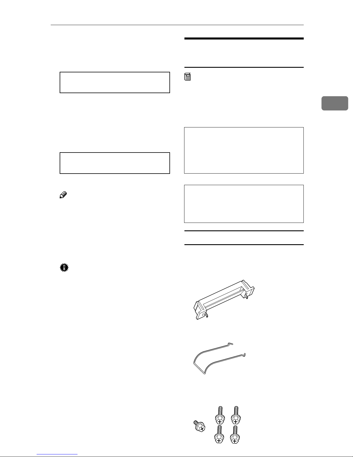
A
❖❖❖❖ User Account Enhance Unit
❖❖❖❖ One Screw
Turn off the power switch and
B
unplug the power cable.
Remove two screws that are fas-
C
tening the Controller Board on
the back of the printer using provided screwdriver.
Holding the handle, pull out the
D
Controller Board slowly.
Put the Controller Board in a flat
E
place.
You will install the User Account
Enhance Unit in the position as
shown in the illustration.
2
ZDJP025J
Reference
See P.20 “How to Use the Screw-
driver”.
ZDJP025J
The removed screws will be used
later to fasten the Controller
Board.
ZDJP702J
35
Page 44

Setting Up
2
Install the User Account Enhance
F
Unit to the Controller Board. If
there is a screw coming out from
the place of attachment, insert the
screw in the hole at the tip of the
User Account Enhance Unit (AAAA)
and push the unit in the direction
of the arrow (BBBB).
Confirm that the User Account Enhance Unit is connected firmly to
the Controller Board.
ZDJP703J
Adjust the Controller Board to the
H
top and bottom rails, and then
push in slowly until it stops.
Insert the Controller Board firmly
by pushing the left area as shown
in the illustration.
ZDJP030J
Tighten the screw to fasten the
G
User Account Enhance Unit using
provided screwdriver.
ZDJP704E
Tighten two screws to fasten the
I
Controller Board back into its
original position using provided
screwdriver.
ZDJP801J
ZDJP031J
36
Page 45

Installing Options
Note
❒ Be sure to return the provided
screwdriver to its original position on the inside of the front
cover.
Note
❒ After finishing all installation
for printing, you can check
whether the User Account Enhance Unit is installed properly.
Print the Configuration Page
from the "List/Test Print"
menu. If it is installed properly,
you will see "Installed" for "Accounting Module".
❒ If the User Account Enhance
Unit is not installed properly,
you will see "Not Installed". In
such a case, reinstall from step
. If you cannot install it prop-
A
erly even after reinstallation,
contact your sales or service
representative.
Installing the Printer Hard Disk
Type 3800C
Important
❒ Be sure to touch a metal object be-
fore touching the Printer Hard
Disk to discharge static electricity.
Even a small amount of static electricity can damage the unit.
❒ Do not subject the Printer Hard
Disk to physical shocks.
Check the contents of the box.
A
❖❖❖❖ Printer Hard Disk Type 3800C
2
Reference
See P.68 “Test Printing”.
❖❖❖❖ Flat Cable
❖❖❖❖ Power Cable
❖❖❖❖ Two Screws
37
Page 46

Setting Up
2
Turn off the power switch and
B
unplug the power cable.
Remove two screws that are fas-
C
tening the Controller Board on
the back of the printer using provided screwdriver.
Reference
See P.20 “How to Use the Screw-
driver”.
ZDJP025J
Install the Printer Hard Disk to
F
the Controller Board.
Tighten two screws to fasten the
G
Printer Hard Disk to the Controller Board using provided screwdriver.
ZDJP036J
The removed screws will be used
later to fasten the Controller
Board.
Holding the handle, pull out the
D
Controller Board slowly.
Put the Controller Board in a flat
E
place.
ZDJP025J
Connect the power cable and flat
H
cable to the Printer Hard Disk.
ZDJP118J
ZDJP035J
38
Page 47

Installing Options
Connect the flat cable to the Con-
I
troller Board.
Connect the power cable to the
J
Controller Board.
ZDJP119J
Insert the Controller Board firmly
by pushing the left area as shown
in the illustration.
Tighten two screws to fasten the
L
Controller Board back into its
original position using provided
screwdriver.
2
ZDJP801J
Adjust the Controller Board to the
K
top and bottom rails, and then
push in slowly until it stops.
ZDJP117J
ZDJP031J
Note
❒ Be sure to return the provided
screwdriver to its original position on the inside of the front
cover.
ZDJP030J
39
Page 48

Setting Up
2
Initializing the printer hard disk drive
After turning the power switch on,
the printer starts initializing the Printer Hard Disk. Format the Printer
Hard Disk following the instruction
on the display panel.
Plug in the power cable and turn
A
on the power switch.
A message for formatting the
Printer Hard Disk is shown on the
panel display.
HDD Error
Initialize?
Press {{{{Enter}}}} to format the Printer
B
Hard Disk.
A message indicating that you
have completed formatting is
shown on the panel display.
HDD initialize
finish:OK
❒ If the Printer Hard Disk is not
installed properly, you will see
"Not Installed". In such a case,
reinstall from step
;. If you
A
cannot install it properly even
after reinstallation, contact your
sales or service representative.
Reference
See P.68 “Test Printing”.
Important
❒ Before using the new Printer
Hard Disk, you must make the
settings in [Accessories] of the
printer driver.
❒ Do not turn off the power
switch while formatting the
Printer Hard Disk to avoid a
malfunction.
Formatting the printer hard disk drive
If it becomes necessary to format the
Printer Hard Disk after initial setup,
execute "HDD Format" in the Maintenance menu.
Press {{{{On Line}}}}.
C
"Ready " appears on the panel display.
Note
❒ After finishing all installation
for printing, you can check
whether the Printer Hard Disk
is installed properly. Print the
Configuration Page from the
"List/Test Print" menu. If it is
installed properly, you will see
"Installed" for "Printer Hard
Disk Drive".
Important
❒ Formatting the Printer Hard Disk
will delete all data.
Press {{{{Menu}}}}.
A
On Line
Job Reset
Menu
Form Fee d
Power Error Data In
Escape
#
Enter
ZDJS001N
"Menu" appears on the panel display.
40
Page 49
Press {{{{UUUU}}}} or {{{{TTTT}}}} to display
R
R
B
"Maintenance", and then press
{{{{OK}}}}.
Installing Options
Installing the Duplex Unit Type
3800C
Menu:
Maintenance
The menu for selecting the Maintenance item is shown.
Press {{{{UUUU}}}} or {{{{TTTT}}}} to display
C
"HDD Format", and then press
{{{{OK}}}}.
Maintenance:
HDD Format
A check message is shown.
Note
❒ If "HDD Format" is not dis-
played on the panel display, the
Printer Hard Disk is not installed properly. Reinstall from
step
install it properly, contact your
sales or service representative.
⇒ P.37. If you still cannot
A
Preparation
If you want to use the optional Paper
Feed Unit at the same time, install
the optional Paper Feed Unit first,
and then install the Duplex Unit.
CAUTION:
• The inside of the machine becomes very hot. Do not touch the
parts with a label indicating a "hot
surface". Touching a "hot surface" could result in a burn.
CAUTION:
• Do not let go of the Duplex Reversal Unit until it is fastened in
place. It could drop and cause an
injury.
Installing the Duplex Reversal Unit Stand
Check the contents of the box.
A
2
Important
❒ Do not turn off the power
switch while formatting the
Printer Hard Disk to avoid a
malfunction.
Press {{{{OK}}}}.
D
The Printer Hard Disk is formatted, and a restart message is
shown.
Turn off the power switch once,
E
and then turn the power back on.
The Printer Hard Disk format is
completed, enabling its use.
❖❖❖❖ Stand
❖❖❖❖ Paper Guide
❖❖❖❖ One Short Screw, Four Long
Screws
41
Page 50

Setting Up
2
❖❖❖❖ Duplex Reversal Unit
❖❖❖❖ Duplex Feed Unit
Remove the adhesive tape and
B
packing materials.
Important
❒ Do not remove the adhesive
tape which hold the auxiliary
bar at this point. Remove it in
step
on P.44 “Installing the Du-
C
plex Reversal Unit”
Turn off the power switch and
C
unplug the power cable from the
wall outlet.
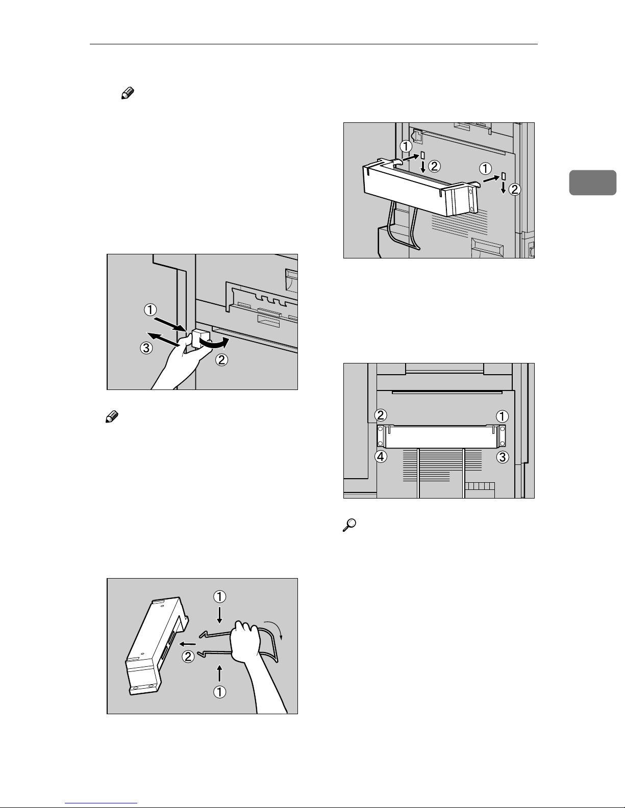
Lift the External Tray in the direc-
D
tion of the arrow (AAAA) and remove
(BBBB).
Remove the two small covers on
E
the upper left cover of the printer.
A Open the upper left cover.
ZDJP038J
❒ Do not remove the adhesive
tape which hold the cable of the
Duplex Reversal Unit at this
point. Remove it in step
G
on
P.44 “Installing the Duplex Rever-
sal Unit”
ZDJP711J
ZDJP039J
B Pinch the two small covers and
pull in the direction of the arrow to remove them.
42
ZDJP040J
ZDJP712J
Page 51
Installing Options
C Close the upper left cover.
Note
❒ You will not use the removed
two covers.
Remove the protective cover on
F
the left side of the printer. Hold
the protective cover by both sides,
and while pushing the left side of
the cover (AAAA), open it in the direction of the arrow (BBBB), and then remove (CCCC).
Insert the claws of the stand into
H
the holes on the left side of the
printer (AAAA), and push down (BBBB).
Tighten four long screws to fasten
I
the Duplex Reversal Unit Stand
using provided screwdriver. Fasten in the order of AAAA⇒⇒⇒⇒BBBB⇒⇒⇒⇒CCCC⇒⇒⇒⇒DDDD
as shown in the illustration.
2
ZDJP043J
Note
❒ You will not use the removed
protective cover.
Attach the paper guide to the
G
stand. Hold the paper guide so
that its right side bends down as
shown in the illustration, and
while holding it lightly (AAAA), insert it into the holes of the stand
(BBBB).
ZDJP041J
ZDJP044J
Reference
See P.20 “How to Use the Screw-
driver”.
This completes the installation of
the stand. Next, install the Duplex
Reversal Unit.
ZDJP042J
43
Page 52

2
Setting Up
Installing the Duplex Reversal Unit
Holding the Duplex Reversal
A
Unit in a level position with both
hands, insert the hooks into the
groove of the stand. At this point,
adjust the tip of the hooks to the
line on the stand (AAAA) and insert
slowly (BBBB). Do not let go of the
Duplex Reversal Unit even after
insertion.
Supporting the Duplex Reversal
C
Unit, remove the adhesive tape
and hold the auxiliary bar in front
of the hook on the left side, and
then stand it up.
Hook the hole of the auxiliary bar
D
on the mounting bracket of the
printer.
ZDJP047J
The hooks of the Duplex Reversal
Unit grasp the bar inside the
groove of the stand.
Supporting the Duplex Reversal
B
Unit, remove the stopper of the
mounting bracket on the printer.
This stopper will be used in a later
step
, so be careful not to lose it.
E
ZDJP045J
ZDJP046J
ZDJP048J
In step
the position shown with a perforated line in the illustration.
, move the auxiliary bar to
E
44
Page 53
Installing Options
Hang the auxiliary bar on the
E
deep left end as shown in the illustration, and then install the
stopper that was removed in step
.
B
Make sure the auxiliary bar and
stopper are installed in the positions shown in the illustration.
Raise the Duplex Reversal Unit
F
slowly, and then adhere it to the
printer.
ZDJP049J
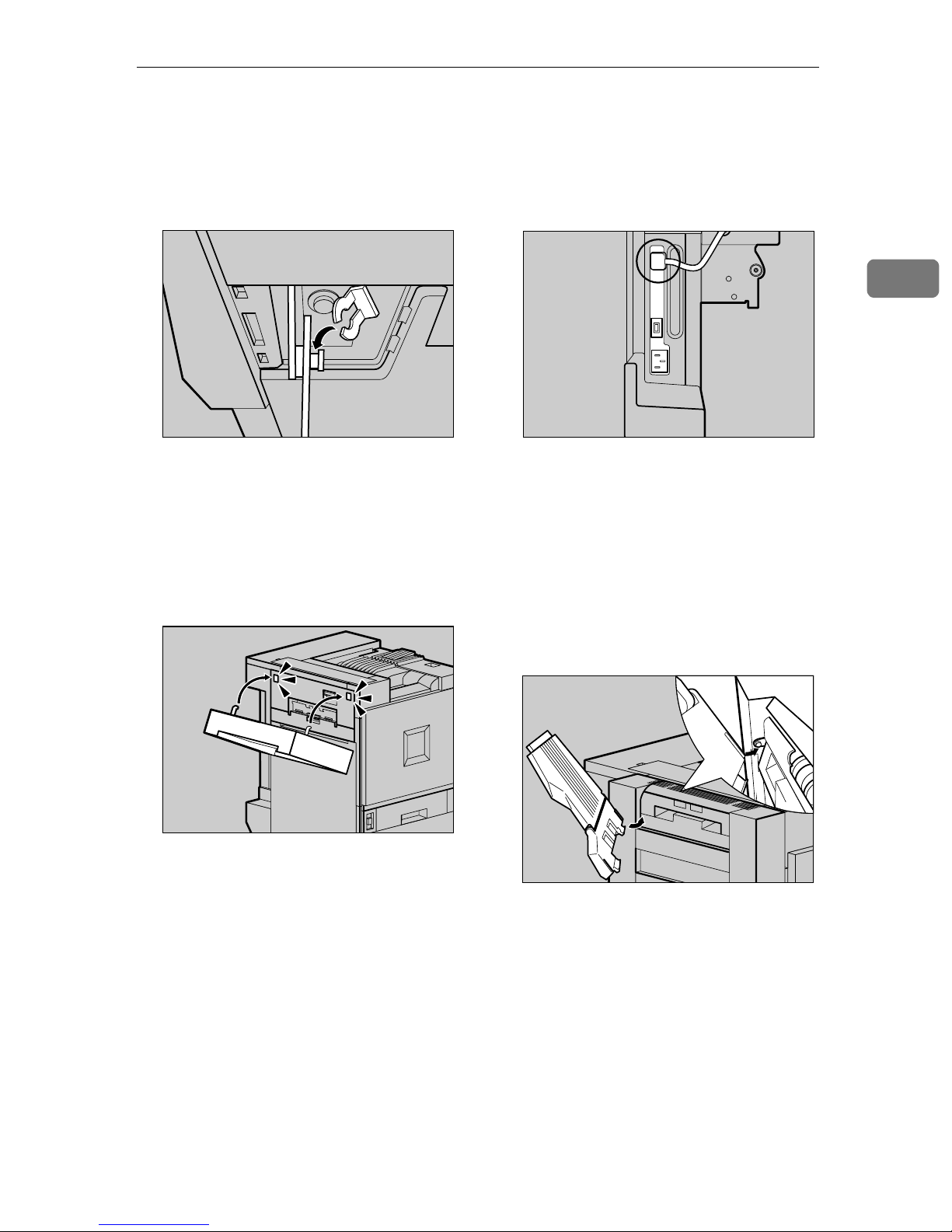
Remove the adhesive tape which
G
hold the cable, and then connect
the cable of the Duplex Reversal
Unit to the upper connector on the
back of the printer.
This completes the installation of
the Duplex Reversal Unit. Install
the Duplex Feed Unit after installing the External Tray.
Install the External Tray.
H
A Stand the External Tray and in-
sert it from the left side with
both hands.
2
ZDJP051J
ZDJP050J
ZDJP052J
45
Page 54
Setting Up
2
B Pushing the right edge of the
External Tray lightly with your
finger (AAAA), insert it (BBBB).
ZDJP053J
C Lower the External Tray to-
ward you.
Holding the Duplex Feed Unit
B
with both hands, place it on the
vertical rail and insert slowly until it stops.
The vertical rail is in the position as
shown in the illustration.
ZDJP056J
Installing the Duplex Feed Unit
Open the front cover slowly by
A
pulling the two points on the left
and right.
ZDJP054J
ZDJH007J
Fasten the Duplex Feed Unit with
C
one short screw using provided
screwdriver.
ZDJP133J
ZDJP057J
46
Page 55

Installing Options
R
Note
❒ Be sure to return the provided
screwdriver to its original position on the inside of the front
cover.
This completes the installation of
the Duplex Feed Unit.
Close the front cover slowly by
D
pressing the two points on the left
and right.
Note
❒ After finishing all installation
for printing, you can check
whether the Duplex Unit is installed properly. Print the Configuration Page from the "List/
Test Print" menu. If it is installed properly, you will see
"Duplex Unit" under the "Options" list.
❒ If the Duplex Unit is not in-
stalled properly, reinstall from
step
stall it properly even after reinstallation, contact your sales or
service representative.
Reference
See P.68 “Test Printing”.
⇒ P.41. If you cannot in-
A
ZDJH041J
Check for spare parts. You will
E
not use these spare parts.
ZDJP058J
Installing the SR770 (2 Tray
Finisher)
Preparation
Install the optional Paper Feed
Unit and optional Memory Unit or
optional Printer Hard Disk first,
and then install the 2 Tray Finisher.
If you want to use the optional
Memory Unit, 1394 Interface Unit,
User Account Enhance Unit and
Printer Hard Disk at the same
time, install these options first, and
then install the 2 Tray Finisher.
CAUTION:
• When moving the 2 Tray Finisher, hold the center of both sides,
and lift slowly. Lifting it carelessly
or dropping it may cause an injury.
Note
❒ The 2 Tray Finisher weighs ap-
proximately 53 kg (116.9 lbs).
2
47
Page 56
Setting Up
2
Important
❒ You cannot install the 2 Tray Fin-
isher unless both the Paper Feed
Unit and Duplex Unit options are
installed.
❒ The 2 Tray Finisher requires the
optional Printer Hard Disk or optional Memory Unit at least 128
MB.
❒ You cannot install the 4-bin Mail-
box and 2 Tray Finisher at the same
time.
Turn off the power switch and
A
unplug the power cable.
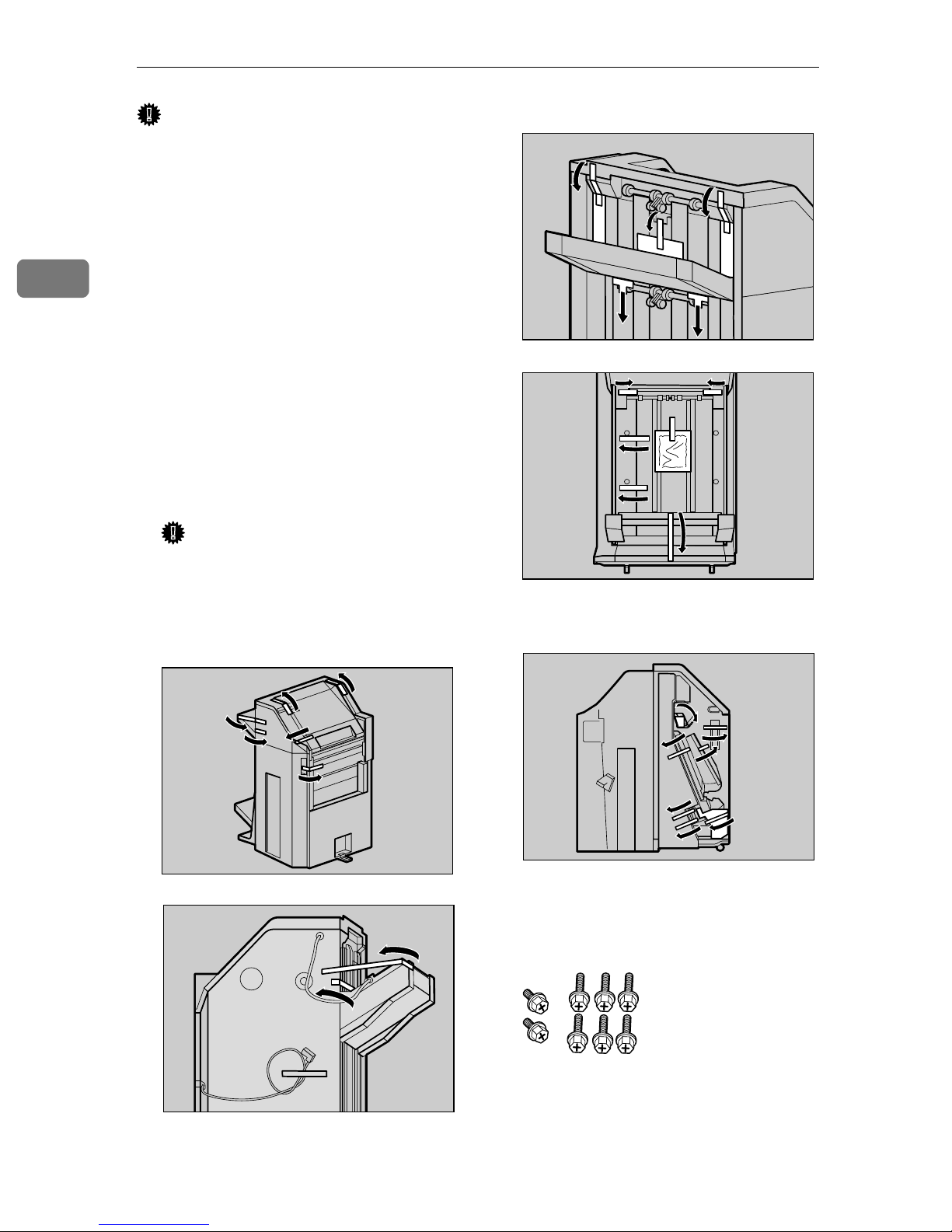
Remove the adhesive tape and
B
packing materials.
Important
❒ Do not remove the adhesive
tape which hold the cable at this
point. Remove it in step
R
.
❖❖❖❖ Front and Side
❖❖❖❖ Back
ZDJP950J
ZDJP060J
❖❖❖❖ Interior
48
ZDJP059J
ZDJP062J
Check the contents of the box.
C
❖❖❖❖ Two short screws, six long screws
ZDJP061J
Page 57
Installing Options
❖❖❖❖ Connecting Bracket
❖❖❖❖ Mounting Bracket
❖❖❖❖ Rail
❖❖❖❖ Two 2 Tray Finisher Trays
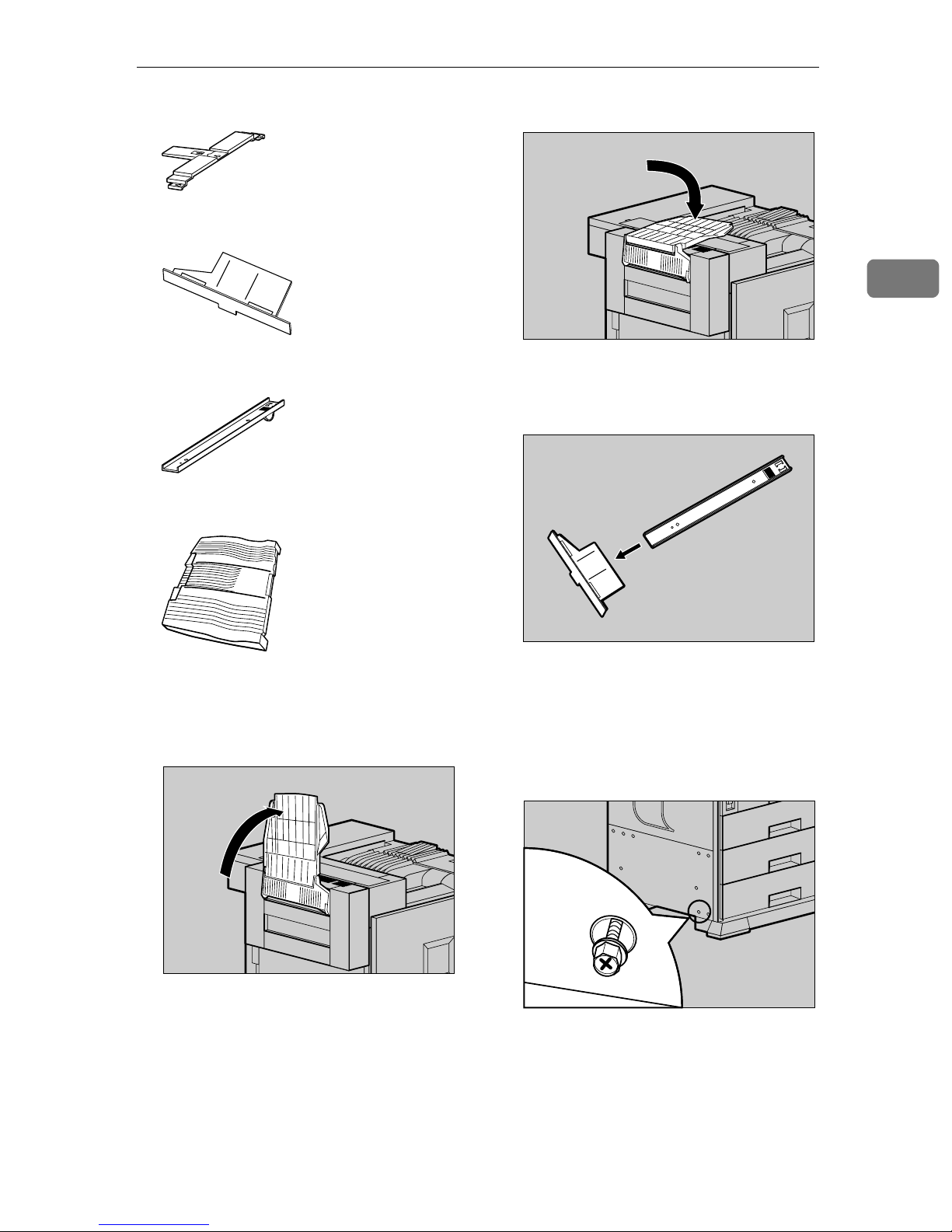
B Fold it into printer.
Insert the rail with a wheel in the
E
mounting bracket.
2
ZDJP065J
Stand the External Tray of the
D
printer.
A Stand it vertically.
ZDJP064J
Temporarily fasten one long
F
screw in the position shown in
the illustration. Turn the screw
three to four times using your
hand.
ZDJP066J
ZDJP067J
49
Page 58

Setting Up
2
Insert the rail, assembled in step
G
, into the bottom area of the
E
printer.
Hook the hole of the mounting
H
bracket on the screw that was
temporarily fastened in step
ZDJP068J
.
F
With the left corner of the mount-
J
ing bracket adjusted to the position shown by the arrow in the
illustration, fasten the left side of
the mounting bracket with a long
screw using provided screwdriver. Also tighten the screw on the
right side that was temporarily
fastened in step
F
.
ZDJP071J
Holding the mounting bracket
I
with both hands, move it in the
direction of up (AAAA) ⇒⇒⇒⇒ right (BBBB).
ZDJP069J
Reference
See P.20 “How to Use the Screw-
driver”.
Temporarily fasten the two long
K
screws in the positions shown in
the illustration of the Duplex Reversal Unit. Turn the screws three
to four times with your hand.
ZDJP072J
50
ZDJP070J
Page 59

Installing Options
Hook the connecting bracket on
L
the screws that were temporarily
tightened in step
Fasten the right side of the con-
M
K
.
necting bracket with a long screw
using provided screwdriver. Also
tighten two screws that were temporarily tightened in step
K
.
ZDJP073J
If you have the 500-sheet Paper
N
Feed Unit installed, change the
position of the connecting bracket on the side of the 2 Tray Finisher to the lower level. Remove two
screws using provided screwdriver, move the connecting bracket
down, and then refasten the
screws.
2
ZDJP075J
ZDJP074J
Note
❒ If you have the 1000-sheet Paper
Feed Unit or 2000-sheet Large
Capacity Tray installed, proceed to step
K
.
Place the rail of the printer on the
O
rail of the 2 Tray Finisher, and
then slide until it stops.
ZDJP076J
ZDJP077J
51
Page 60

Setting Up
2
Fasten the rails with a long screw
P
using provided screwdriver.
Push the 2 Tray Finisher slowly
Q
toward the printer until it stops.
ZDJP078J
Connect the cable of the 2 Tray
S
Finisher to the lower connector on
the back of the printer.
Install the two 2 Tray Finisher
T
Trays to the 2 Tray Finisher.
Note
❒ The two Fnisher Trays are iden-
tical.
Remove the tape that is fastening
R
the cable to the 2 Tray Finisher.
A Adjust the notch on the left
side of the 2 Tray Fnisher Tray
to the cable coming out from
the 2 Tray Finisher.
ZDJP202J
ZDJP082J
ZDJP080J
52
Page 61

Installing Options
B With the 2 Tray Fnisher Tray
laid horizontally, slide it in at a
slant until it stops.
ZDJP083J
C Fasten the Fnisher Tray with a
short screw using provided
screwdriver.
Return the Fnisher Tray that is in-
U
stalled on the Duplex Unit back
into place.
A Lift the top.
B Lower slowly.
2
ZDJP085J
ZDJP084J
D Use the same steps (steps B
and C) to install the other 2
Tray Fnisher Trays.
Note
❒ Be sure to return the provid-
ed screwdriver to its original
position on the inside of the
front cover.
ZDJP086J
Note
❒ After finishing all installa-
tion for printing, you can
check whether the Finisher is
installed properly. Print the
Configuration Page from the
"List/Test Print" menu. If it is
installed properly, you will
see "2 Tray Finisher" under
the "Options" list.
❒ If the Finisher is not installed
properly, reinstall from step
. If you cannot install it
A
properly even after reinstallation, contact your sales or
service representative.
Reference
See P.68 “Test Printing”.
53
Page 62

Setting Up
R
R
2
Installing the Mail Bin Type
3800C (4-bin Mailbox)
Preparation
If you want to use the optional Paper Feed Unit at the same time, install the optional Paper Feed Unit
first, and then install the 4-bin
Mailbox.
CAUTION:
• When moving the 4-bin Mailbox,
hold the center of both sides, and
lift slowly. Lifting it carelessly or
dropping it may cause an injury.
Note
❒ The 4-bin Mailbox weighs approx-
imately 7 kg (15.5 lbs).
CAUTION:
• When installing the 4-bin Mailbox, be sure to hold both sides. If
you hold it by the bottom, you
might get your hand caught and
injured.
Important
❒ Do not remove the adhesive
tape that is fastening the cable at
this point. Remove it in step
Check the contents of the box.
C
❖❖❖❖ Two Screws
❖❖❖❖ Four Output Bins
❖❖❖❖ Labels
>PS< >PS< >PS< >PS< >PS<
>PS< >PS< >PS< >PS< >PS<
>PS< >PS< >PS< >PS< >PS<
M
.
Important
❒ You cannot install the 4-bin Mail-
box and 2 Tray Finisher at the same
time.
Turn off the power switch and
A
unplug the power cable.
Remove the attached package.
B
ZDJP087J
Remove the top cover. Draw the
D
lever (AAAA) and lift (BBBB) to remove.
There is an opening for installing
the 4-bin Mailbox.
Note
❒ You will not use the removed
cover.
ZDJP089J
54
Page 63

Installing Options
Holding both sides of the 4-bin
E
Mailbox with both hands, stand
on the left side of the printer.
Lower it slowly to fit into the
openings, and then insert until
you hear a click.
If the Duplex Unit is installed, proceed to step
Pull up the External Tray in the
F
G
.
direction of the arrow (AAAA), and
then remove (BBBB).
ZDJP090J
If the Duplex Unit is installed,
G
open the Duplex Reversal Unit.
A Push up the lock release but-
ton, and keep in that position.
B Lower the Duplex Reversal
Unit slowly until it stops.
2
ZDJP092J
ZDJP038J
Open the upper left cover.
H
ZDJP093J
ZDJP094J
55
Page 64

Setting Up
2
Fasten the 4-bin Mailbox with
I
two screws using provided screwdriver.
Reference
See P.20 “How to Use the Screw-
driver”.
Note
❒ Be sure to return the provided
screwdriver to its original position on the inside of the front
cover.
ZDJP095J
If the Duplex Unit is installed, re-
L
turn the Duplex Reversal Unit to
its original position. Lift it slowly
until you hear a click.
Remove the adhesive tape of the
M
cable of the 4-bin Mailbox.
ZDJP098J
Close the upper left cover.
J
If the Duplex Unit is installed, proceed to step
Install the External Tray to the
K
printer. Hook the External Tray to
the slits of the printer, and then
lower the tray toward you.
L
.
ZDJP096J
Check that the cable of the 4-bin
N
Mailbox is in the position as
shown in the illustration.
If it is not, change its position in the
direction of (A) ⇒ (B).
ZDJP994J
ZDJP091J
56
Page 65
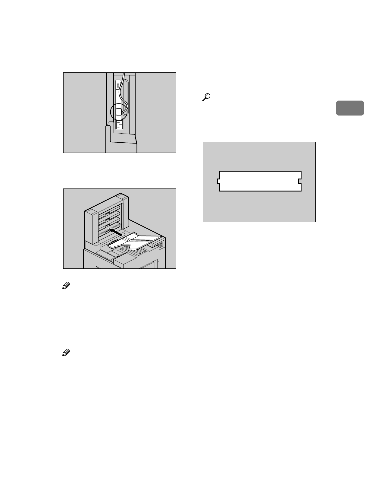
Installing Options
Connect the cable of the 4-bin
O
Mailbox to the lower connector
on the back of the printer.
Insert four output bins in order,
P
starting from the bottom.
ZDJP100J
❒ If the 4-bin Mailbox is not in-
stalled properly, reinstall from
step
properly even after reinstallation, contact your sales or service representative.
Reference
See P.68 “Test Printing”.
Check for spare part. You will not
Q
use this spare part.
. If you cannot install it
A
2
ZDJP099J
Note
❒ If you have decided to assign
Mail Box Bins to individuals
and departments decided, write
their names on the labels provided and stick them to the
sides of the 4-bin Mailbox.
Note
❒ After finishing all installation
for printing, you can check
whether the 4-bin Mailbox is installed properly. Print the Configuration Page from the "List/
Test Print" menu. If it is installed properly, you will see "4bin Mailbox" under the "Options" list.
ZDJP101J
57
Page 66

Setting Up
R
R
Installing the Toner Cartridge
2
WARNING:
• Do not incinerate spilled toner
or used toner. Toner dust is
flammable and might ignite
when exposed to an open
flame.
• Disposal should take place at
an authorized dealer or an appropriate collection site. If you
dispose of the used toner cartridges yourself, dispose of
them according to local regulations.
CAUTION:
• The inside of the machine becomes very hot. Do not touch the
parts with a label indicating a "hot
surface". Touching a "hot surface" could result in a burn.
Open the upper right cover.
A
Take out the toner cartridges from
B
the box.
ZDJT006J
• Keep toner (used or unused) and
the toner cartridge out of reach of
children.
• Our products are engineered to
meet the highest standards of
quality and functionality. When
purchasing expendable supplies,
we recommend using only those
provided by an authorized dealer.
Note
❒ The toner cartridge allows you to
print up to about 20,000 pages in
black, and about 10,000 pages in
color. These numbers were obtained from printing A4K 5%
charts, and the actual number of
pages will differ depending on the
paper type, size, contents and settings.
Note
❒ The black (K) toner cartridge
contains more than the other
toner cartridges.
Shake the toner cartridge back
C
and forth about 5 - 6 times.
ZDJT202J
58
ZDJT203J
Page 67

Installing the Toner Cartridge
Holding the toner cartridge with
D
the metal contact area in front, attach in the direction of the arrow.
Attach the toner cartridges in the
order of magenta (M), cyan (C),
yellow (Y), and black (K).
Important
❒ Be careful not to touch the metal
contact point with your fingers.
ZDJT004J
Close the upper right cover.
G
Important
❒ Do not turn off the power
switch during "Loading Toner..." appears on the panel display to avoid a printer
malfunction.
2
ZDJH042J
Insert the toner cartridge slowly
E
until the green hook snaps on the
metal contact area.
Important
❒ Do not insert and remove the
toner cartridges over and over.
This could result in a toner leak.
Use the same steps to attach the
F
remaining three toner cartridges.
ZDJT005J
59
Page 68
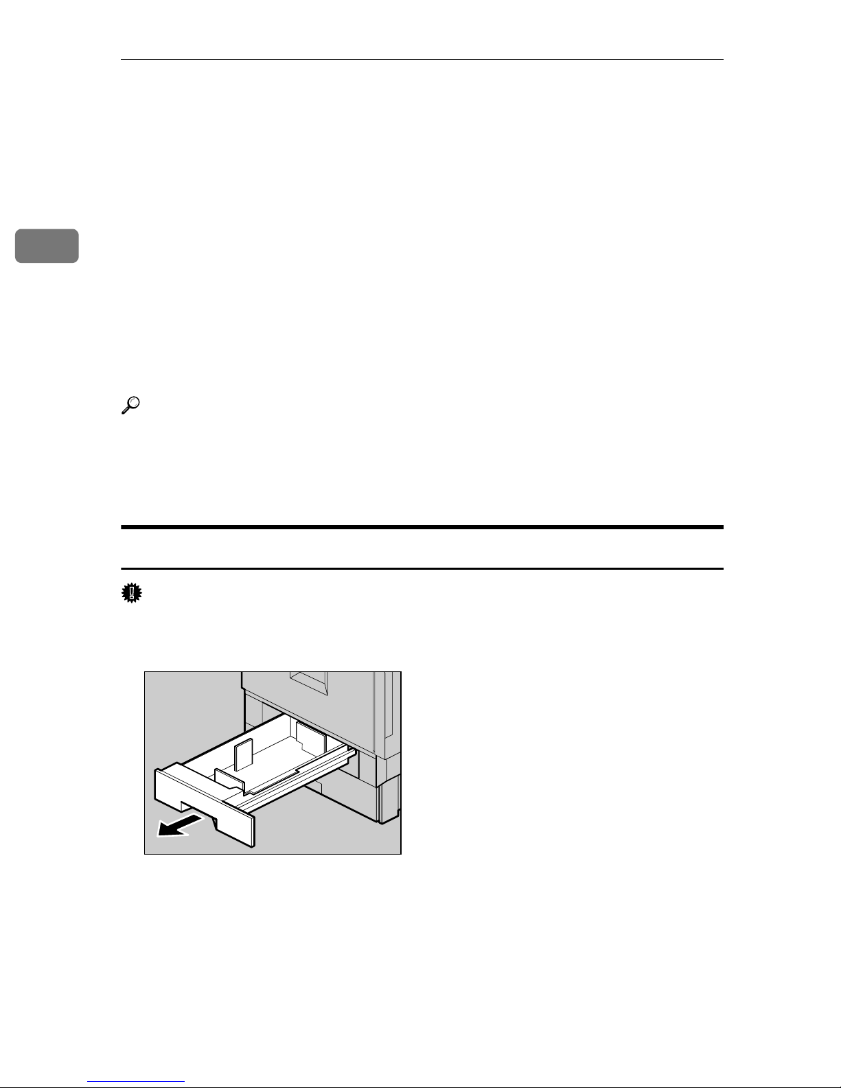
2
Setting Up
Loading Paper
This section shows how to load paper in the paper tray. If you do not load paper,
the setup procedure will not complete properly.
The side guide and end guide of each paper tray is set to the following values at
factory default. The loading procedure is different if you choose to load paper
that is a different size from that of factory default.
⇒ P.60 “Loading Paper in Tray 1”
⇒ P.62 “Changing the settings”
❖❖❖❖ Settings of the Paper Trays at Factory Default
• Tray 1 (Standard): 11" × 81/2"K exclusive
• 2000-sheet Large Capacity Tray (Optional): 11" × 8
Reference
For more information on the size and feed direction of paper that can be loaded in the tray, see "Paper Types and Sizes" in Maintenance Guide 2.
1
/2"K exclusive
For more information on loading paper in the Bypass Tray, see "Load Paper in
the Bypass Tray" in Maintenance Guide 2.
Loading Paper in Tray 1
Important
❒ Tray 1 is 11" × 8
Slide the paper tray out slowly until it stops.
A
1
/2"K paper exclusive. Load only the 11" × 81/2" size paper.
ZDJH003J
60
Page 69
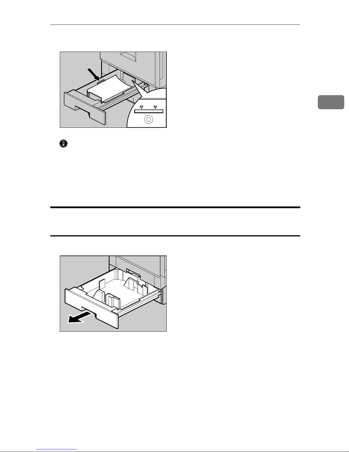
Loading Paper
Align all four sides of the paper stack, and then load it in the tray.
B
ZDJY001J
Important
❒ Confirm that the top of the stack is not higher than the Limit mark inside
the tray.
❒ Be sure to adjust the side guides to the paper size, or paper misfeeds might
occur.
2
Slide the paper tray back slowly until it stops.
C
Tray 2 (Standard), 500-sheet Paper Feed Unit, 1000-sheet Paper
Feed Unit
Slide the paper tray out slowly until it stops.
A
ZDJH005J
61
Page 70

2
Setting Up
Align all four sides of the paper stack, and then load it in the tray.
B
ZDJY002J
Important
❒ Confirm that the top of the stack is not higher than the Limit mark inside
the tray.
Slide the paper tray back slowly until it stops.
C
Important
❒ Do not slide the paper tray in with force. If you do, the front and side guide
might move.
❒ Be sure to adjust the side guides to the paper size, or paper misfeeds might
occur.
Changing the settings
Important
❒ Tray 1 is 11" × 8
❒ If you want to load the A4 paper in 2000-sheet Large Capacity Tray (optional),
contact your sales or service representative.
The following example describes changing the settings for Tray 2.
Slide the paper tray out slowly until it stops.
A
1
/2"K paper exclusive. Load only the 11" × 81/2" size paper.
62
ZDJH005J
Page 71

Release the lock of the side guide.
B
ZDJY003J
Align all four sides of the paper stack, and then load it in the tray.
C
Loading Paper
2
ZDJY901J
Important
❒ Confirm that the top of the stack is not higher than the Limit mark inside
the tray.
Pressing the green lever of the side guide (AAAA), adjust it to the loaded paper
D
size (BBBB).
ZDJY006J
63
Page 72
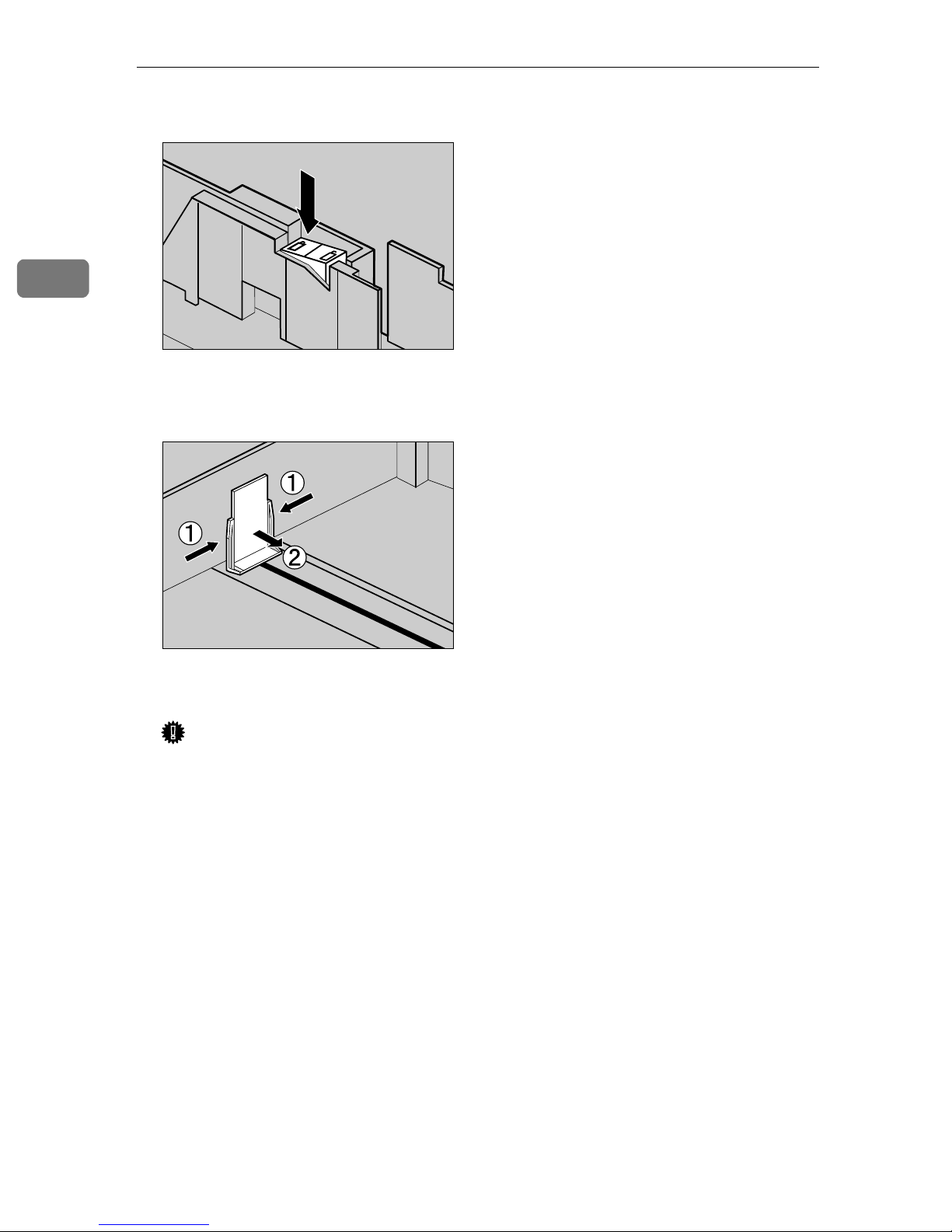
2
Setting Up
After checking that the paper is fixed in place, lock the side guide.
E
ZDJY007J
Gripping both edges of the end guide (AAAA), move it to the position of the
F
loaded paper (BBBB).
ZDJY005J
Slide the paper tray back slowly until it stops.
G
Important
❒ Do not slide the paper tray in with force. If you do, the front and side
guides might move.
❒ Be sure to adjust the side guides to the paper size, or paper misfeed might
occur.
64
Page 73
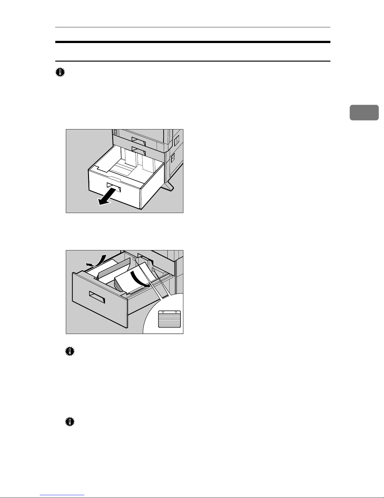
Loading Paper
2000-sheet Large Capacity Tray
Important
❒ The 2000-sheet Large Capacity Tray is set to 11" × 8
❒ If you want to load the A4 paper in the 2000-sheet Large Capacity Tray (op-
tional), contact your sales or service representative.
1
/2"K at factory default.
Slide the paper tray out slowly until it stops.
A
ZDJY008J
Align all four sides of the paper stack, and then load two stacks next to each
B
other.
2
Important
❒ Be sure to align the paper and load them against the left and right walls, or
it could result in a paper misfeed.
❒ Confirm that the top of the stack is not higher than the Limit mark inside
the tray.
Slide the paper tray back slowly until it stops.
C
Important
❒ Do not forcefully slide in the paper tray. This may skew the paper stack
and cause misfeeds.
ZDJY009J
65
Page 74

Setting Up
R
Turning the Power On
2
WARNING:
• Plug and unplug the power cable with dry hands, or it could
result in an electric shock.
Confirm that the power switch is
A
set to "cccc Stand by".
Stand by
ZDJH029N
Connect the power cable to the
B
connector on the back of the
printer.
Turn the power switch to "aaaa On".
D
Stand by
ZDJH031N
Plug in the power cable.
C
Important
❒ Make sure the power cable is
plugged securely into the wall
outlet.
❒ Turn the power switch off when
plugging and unplugging the
power plug.
66
ZDJH030J
Page 75

Selecting the Panel Display Language
Selecting the Panel Display Language
Select a language following the procedures described.
The message for the selected language will appear on the panel display.
Note
❒ The default setting is English.
❒ If you want to use the English pan-
el display, the following procedures are unnecessary.
Press {{{{Menu}}}}.
A
On Line
Job Reset
Menu
Form Feed
Power Error Data In
Escape
#
Enter
Press {{{{Enter}}}}.
C
On Line
Job Reset
Menu
Form Fee d
Power Error Data In
Escape
#
Enter
The following message appears on
the panel display.
Language:
*English
Press {{{{UUUU}}}} or {{{{TTTT}}}} until the lan-
D
guage you want to select appears
on the panel display.
2
ZDJS021N
"Menu" appears on the panel display.
Press {{{{UUUU}}}} or {{{{TTTT}}}} to display "Lan-
B
guage".
Menu:
Language
ZDJS001N
Press {{{{Enter}}}}. Wait for two sec-
E
onds.
"Menu" appears on the panel display.
Press {{{{On Line}}}}.
F
On Line
Job Reset
Menu
Form Fee d
Power Error Data In
Escape
#
Enter
"Ready " message appears on the
panel display.
ZDJS022N
Ready
67
Page 76

Setting Up
Test Printing
2
Test print in order to check that the
printer prints normally. Test printing
checks the printer actions, and does
not test the connection to the host
computer.
Here, you will print the Configuration Page to check the options.
Press {{{{Menu}}}}.
A
On Line
Menu
Job Reset
Form Feed
Power Error Data In
"Menu" appears on the panel display.
Escape
#
Enter
ZDJS001N
Press {{{{UUUU}}}} or {{{{TTTT}}}} to display the
C
"Config. Page", and then press
{{{{OK}}}}.
List/Test Print:
Config. Page
The following message appears
and the Configuration Page is
printed.
Printing...
Note
❒ If printing is not normal, check
to see if an error message is
shown on the panel display. If
there is an error message, see
"Troubleshooting" in Maintenance Guide 2.
Menu:
Paper Input
Press {{{{UUUU}}}} or {{{{TTTT}}}} to display "List/
B
Test Print", and then press {{{{OK}}}}.
Menu:
List/Test Print
The menu for selecting the contents to be test printed is shown.
Check the options.
D
Note
❒ For details about the Configura-
tion Page, see "Interpreting the
Configuration Page" in Administrator Reference 2.
Press {{{{On Line}}}}.
E
"Ready " appears on the panel display.
68
Page 77

Connecting the Printer
Connection to a Network
Turn off the power switch.
A
Loop the network interface cable
B
and attach the ferrite core.
Note
❒ The network interface cable
loop should be about 15 cm (6")
(A) from the end of the cable
(on the end closest to the printer).
Connecting the Printer
Connect the other end of the net-
D
work interface cable to network
equipment, such as a hub.
Reference
For details about settings for the
network environment, see Administrator Reference 1.
Reading the LED lamps
1
2
Connect the network interface ca-
C
ble to the port on the right side of
the printer.
2
ZDJH032J
1. Yellow: Lights up when
100BASE-TX is being used. Turns
off when 10BASE-T is being used.
2. Green: Lights up when the printer
is connected properly to the network.
ZDJP103J
69
Page 78

2
Setting Up
Parallel Connection
Use an interface cable to connect the printer to the host computer with a parallel
connection. The parallel interface cable is not provided with the printer.
Note
❒ Printer's parallel connection is a standard bidirectional interface. It requires a
standard 36-pin parallel cable compliant with IEEE 1284 and a parallel port
available on the host computer.
❒ Use shielded interface cables. Using a cable other than a shielded cable could
result in radio interference noise.
Turn off the printer and host computer power.
A
Connect the cable to the Parallel Port on the right side of the printer, and
B
then fasten with both clasps.
ZDJH033J
Connect the other end of the cable to the interface connector of the host
C
computer.
Reference
For details about settings for printing with a parallel connection, see Printer Client Reference 1.
70
Page 79

INDEX
I
1394 Interface Unit Type1045
4-bin Mailbox/2 Tray Finisher Port
, 19,
B
Bypass Tray
,
2
C
Caution
Checking the Contents of the Box
Configuration Page
Connecting the Printer
Connection to a Network
Connector
Controller Board
,
ii
,
,
68
,
69
,
69
3
,
2
D
,
,
,
,
3
4
67
,
19
,
18
3
,
41
Development Unit
Display Language
Duplex Unit
Duplex Feed Unit
Duplex Reversal Unit
Duplex Unit Port
Duplex Unit Type 3800C
Dustproof Filter
E
Energy Star
Ethernet Port
Exclusive Screwdriver
External Tray
,
iv
,
,
2
,
20
3
F
Front Cover
Fuser Oil Unit
Fusing Unit
,
,
2
, 4,
4
14
G
Guide to the Printer
,
Exterior -Front View
Exterior -Rear View
,
Inside
Operation Panel
4
,
2
,
3
5
,
31
,
10
,
,
41
4
,
16
,
46
,
44
,
20
Inner Cover
3
Installing Options
Installing the Duplex Unit
Duplex Feed Unit
Duplex Reversal Unit
Stand
Installing the Paper Feed Unit
L
Loading Paper
,
60
M
Mail Bin Type 3800C (4-bin Mailbox)
Memory Unit Type B (SDRAM Module)
, 18,
, 19,
54
29
O
Operation Panel
, 2,
5
P
Paper Bank PS470
(2000-sheet Large Capacity Tray)
PAPER FEED UNIT Type 3800C (500 × 1)
18, 21, 61
PAPER FEED UNIT Type 3800C (500 × 2)
18, 24, 61
3
,
,
70
2
,
4
2
Parallel Connection
Parallel Port
Photoconductor Unit
Power Port
Power Switch
Printer Hard Disk Type 3800C
,
,
, 18, 26,
, 19,
65
,
,
37
R
Reading the LED Lamps
,
69
S
Safety Information
Setting Up
SR770 (2 Tray Finisher)
Standard Tray
,
,
ii
7
, 18,
47
,
2
71
Page 80

T
60
61
,
68
, 4,
58
,
66
Test Printing
Toner Cartridge
Tray 1
Tray 2
Turning the Power On
, 2,
, 2,
U
,
,
,
12
3
2
Unpacking the Printer
Upper Cover
Upper Left Cover
Upper Right Cover
User Account Enhance Unit Type B
User Account Enhance Unit TypeB
,
2
W
Warning
Waste Toner Bottle
Where to Put the Printer
,
ii
,
4
,
7
,
,
19
34
72
UE USA G060
Page 81

Copyright © 2001
Page 82

UE USA G060-6900
 Loading...