

Page 1

Adjustment and Color
Memory
Memory
Adjustment and Color
123
Page 2
Color Balance—Adjusting and Storing the Color Balance
Color Balance—Adjusting and Storing the Color Balance
This function allows you to control the overall color tone of copies by adjusting the Y ellow, Magenta, Cyan and
Black color balance. Nine levels of tone are available.
Reference
For copy sample, ☛ see page 19.
Note
❐ The color balance will return to the default when:
• The machine is automatically reset.
• The Clear Modes key is pressed.
• The operation switch is turned off.
• The main power switch is turned off.
❐ You can store and adjustments you make in memory and recall them later.
❐ You can sample color balance. ☛ See page 126.
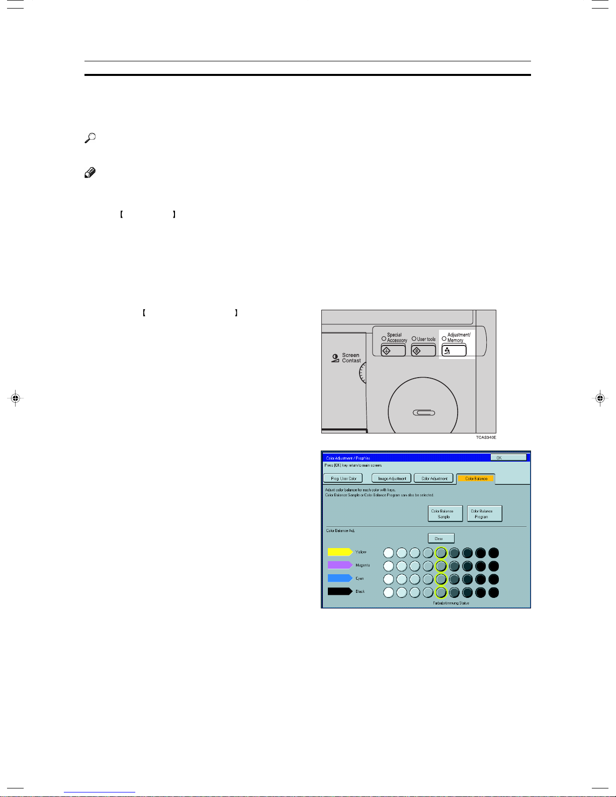
Color Balance Adjustment
Press the Adjustment/Memory key.
1
Make sure that the [Color Balance] key is se-
2
lected.
Adjust the color balance, then press the [OK]
3
key.
124
Page 3
Color Balance—Adjusting and Storing the Color Balance
Color Balance Program—Storing and Recalling the Color Balance
You can store the color balance setting in memory and recall it when you want to use it.
Note
❐ You can store up to three color balance.
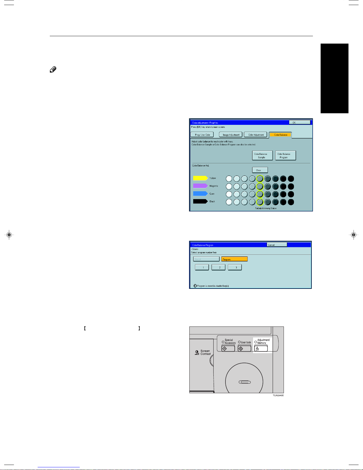
Storing the adjusted color balance
Change the color balance (☛ see page 124),
1
but don’t press the [OK] key.
Press the [Color Balance Program] key.
2
Memory
Adjustment and Color
Press the [Program] key.
3
Select a number for this setting.
4
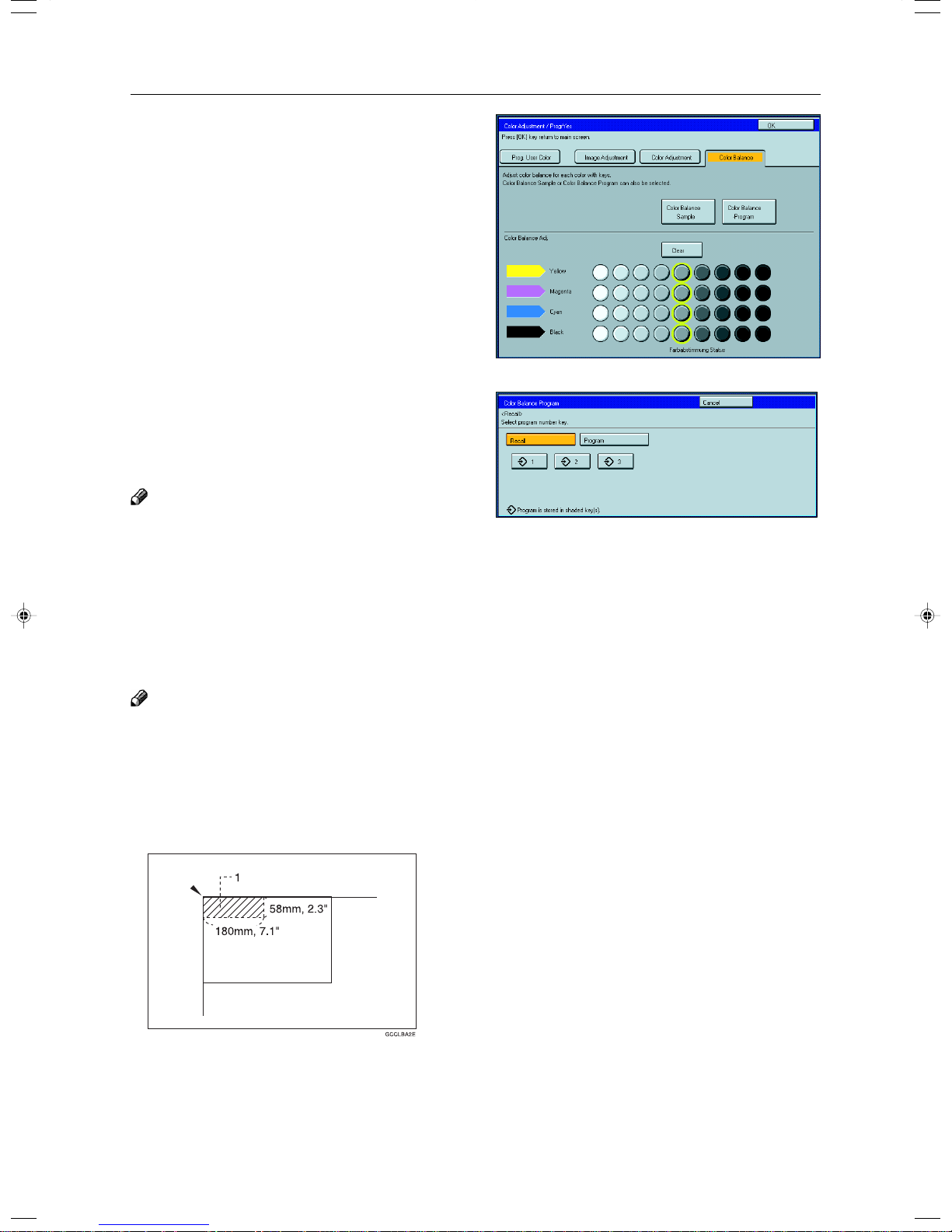
Recalling the color balance
Press the Adjustment/Memory key.
1
Make sure that the [Color Balance] key is se-
2
lected.
125
Page 4
Color Balance—Adjusting and Storing the Color Balance
Press the [Color Balance Program] key.
3
Make sure that the [Recall] key is selected.
4
Select the setting you want to recall.
5
Note
❐ Only color balance programs with m contain a color
balance.
Color Balance Sample—Sampling the Color Balance
Adjusting the color balance by trial and error could require many copies. The color balance sampling function
allows you to produce nine samples on two copies. The first sample of each sheet uses the current color
balance (standard). Each sample after that changes one toner color by a fixed number of steps.
Note
❐ The sample will be copied on two A4p, 81/2" × 11"p sheets or two A3l, 11" × 17"l sheets.
❐ Selecting Color Balance Sample does not reset the adjustments, allowing you to make many samples while
progressively changing the balance. The sample might yield a color balance outside the copier’s range which will be
reproduced on the sample but not on the copy.
For example, if yellow is already adjusted to +3 and you select Sample ±4, the yellow samples will be copied at yellow
+7 and –1, but the adjustment for the final copy cannot be set to +7.
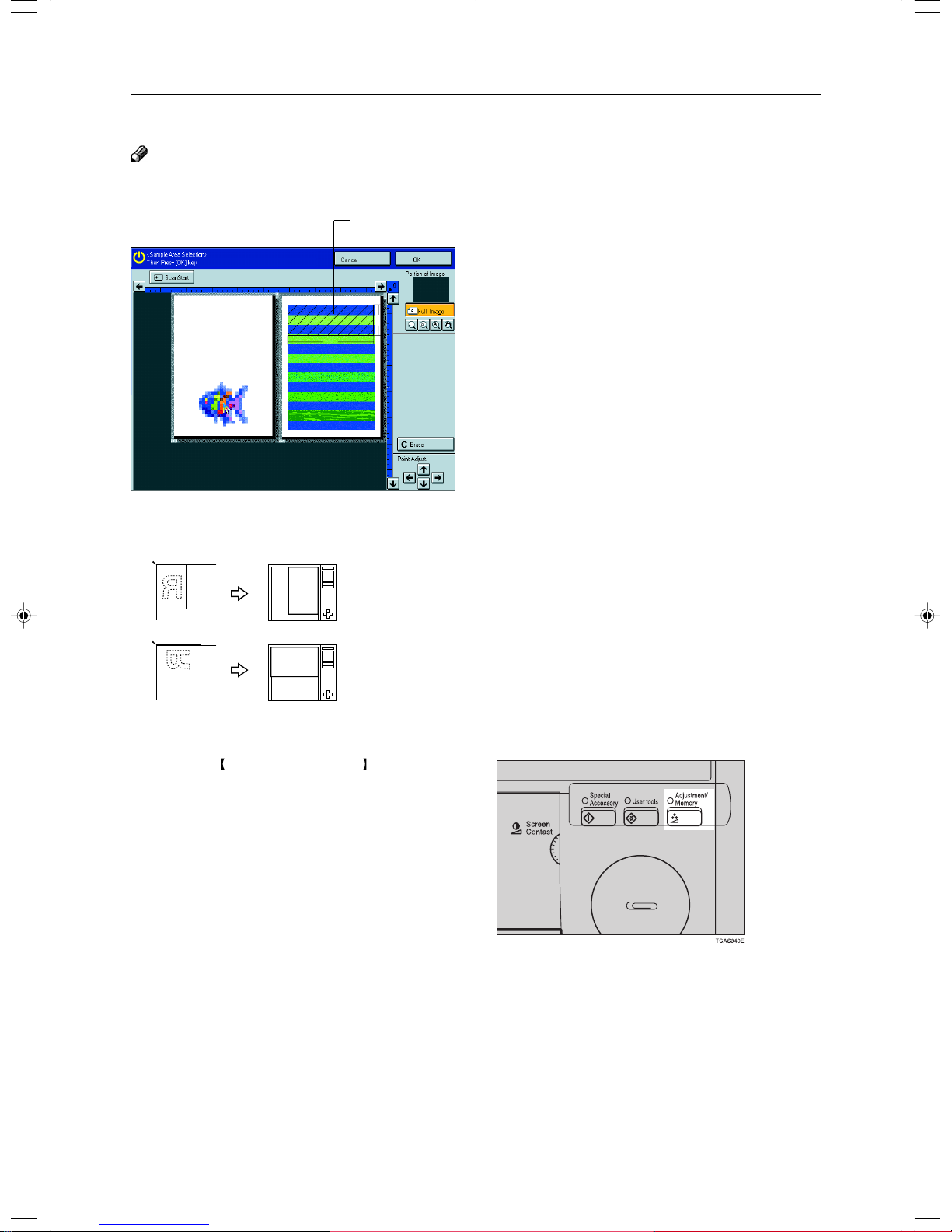
❐ The sampled area is as shown in the illustration.
1: Sampled area
❐ If your machine is Edit type, you can select the sampled area. ☛ See page 128.
126
Page 5
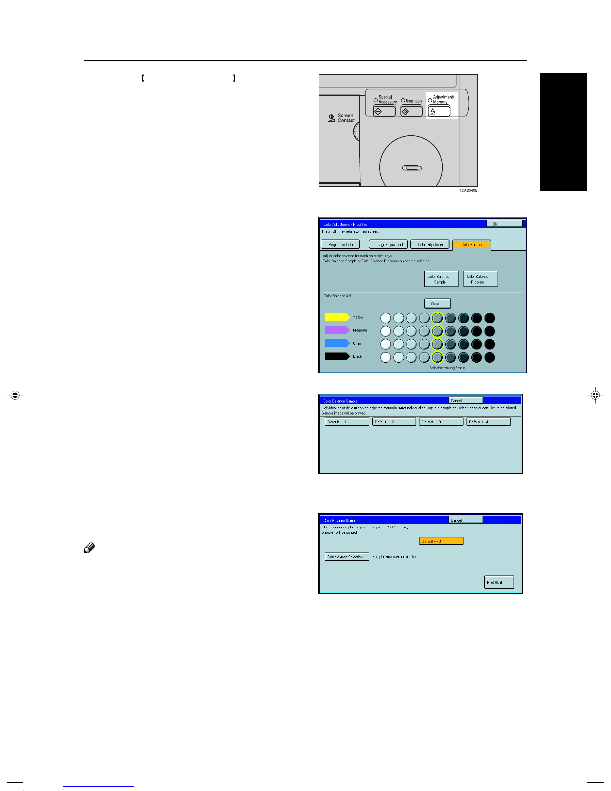
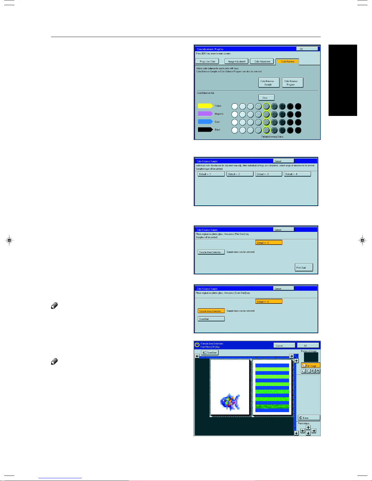
Press the Adjustment/Memory key.
1
Make sure the [Color Balance] key is selected.
2
Press the [Color Balance Sample] key.
3
Color Balance—Adjusting and Storing the Color Balance
Memory
Adjustment and Color
Select the range of densities (standard is the
4
current setting).
Set your original on the exposure glass.
5
Press the [Print Start] key.
6
Note
❐ The sample is copied.
Select the color balance that you want to set,
7
then press the [OK] key.
127
Page 6
Color Balance—Adjusting and Storing the Color Balance
Selecting the sampled area (Only for Edit type)
Note
❐ The sampled area is as shown below.
a: 58mm, 2.3"
b: 180mm, 7.1"
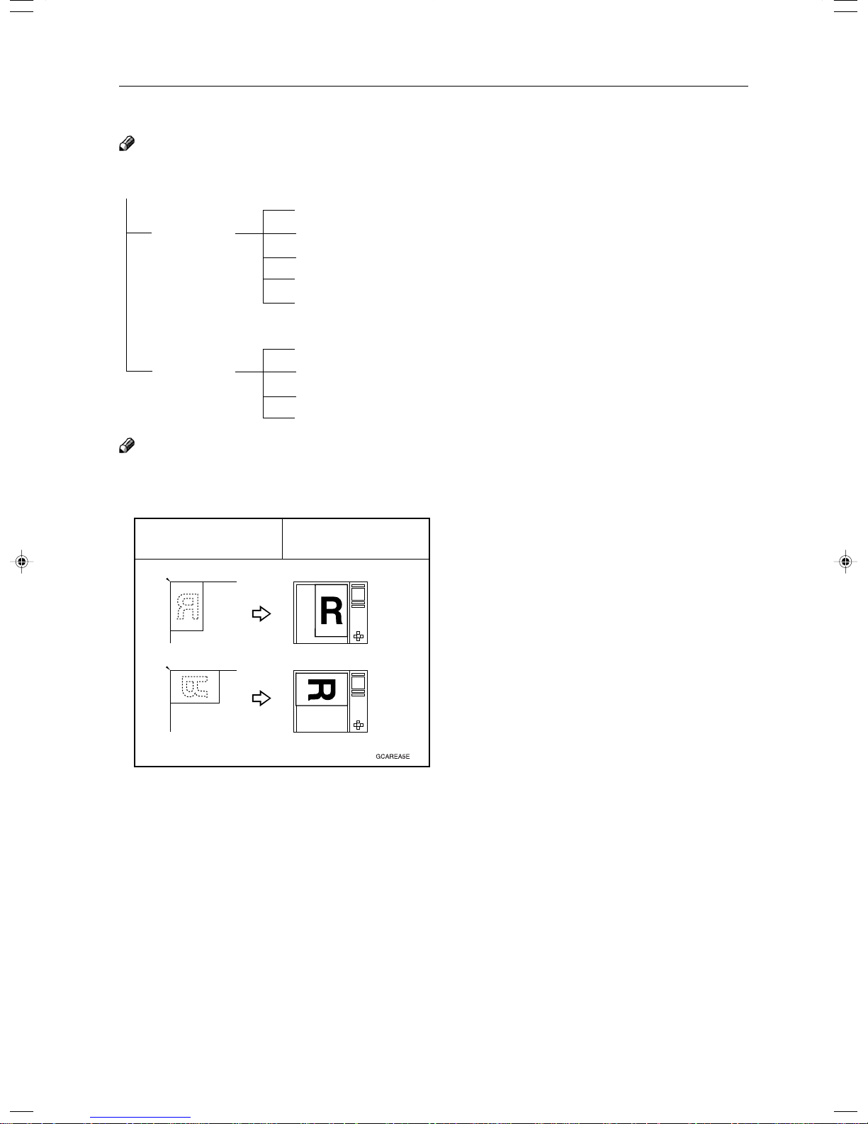
❐ Orientation of the original and scanned image are related as shown:
Selected position
+
<
b
Sampled area
<
a
<
>
Exposure Glass Display
R
R
Press the Adjustment/Memory key.
1
GCAREA5E
128
Page 7
Make sure the [Color Balance] key is selected.
2
Press the [Color Balance Sample] key.
3
Select the range of densities (standard is the
4
current setting).
Color Balance—Adjusting and Storing the Color Balance
Memory
Adjustment and Color
Set your original on the exposure glass.
5
Press the [Sample Area Selection] key.
6
Press the [Scan Start] key.
7
Note
❐ The image of the original is displayed.
Point at the center of the area with the editor
8
pen, then press the [OK] key.
Note
❐ For details about this display, ☛ see page 142.
129
Page 8

Color Balance—Adjusting and Storing the Color Balance
Press the [Print Start] key.
9
Note
❐ The sample is copied.
Select the color balance that you want to set,
0
then press the [OK] key.
130
Page 9
Color Adjustment
Color Adjustment
This function lets you alter up to three single colors by mixing them with adjacent colors in the color circle. For
example, yellow can be shifted towards red to make orange, or towards green to make a yellow green. Note
that only areas of the image containing this color will be modified.
Reference
For copy samples, ☛ see page 20.
Note
❐ This function requires Full Color mode or Auto Color Select mode.
❐ The single color adjustment will return to the default when:
• The machine is automatically reset.
Clear Modes key is pressed.
• The
• The operation switch is turned off.
• The main power switch is turned off.
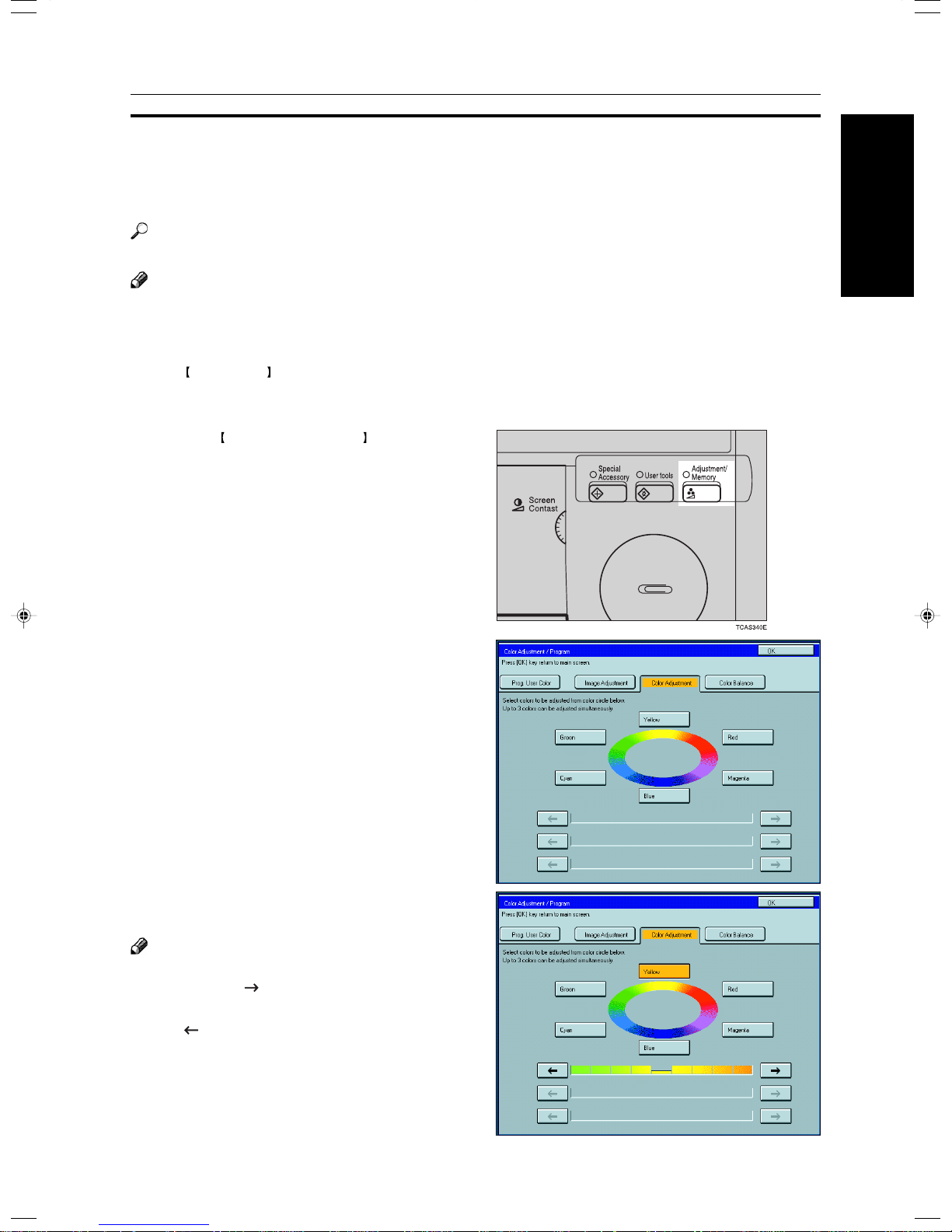
Press the Adjustment/Memory key.
1
Press the [Color Adjustment] key.
2
Select the color key that you want to adjust from
3
the color circle.
Memory
Adjustment and Color
Adjust the color with the keys.
4
Note
❐ For example, if you wish to make yellow appear more
red, press the [
❐ If you wish to make yellow appear more green, press
the [ ] key.
Press the [OK] key.
5
] key.
131
Page 10
Image Adjustment
You can change the following default settings for image adjustment:
Image Adjustment
Soft/Sharp
Contrast
Background Density
Pastel
You can adjust the edges of the image to make the image sharper or softer.
Reference
❐ For copy samples, ☛ see page 20.
Note
❐ Default: level 4
You can adjust the contrast between light parts and dark parts of the image.
Reference
❐ For copy samples, ☛ see page 20.
Note
❐ Default: level 5
You can adjust the background density control.
Reference
❐ For copy samples, ☛ see page 20.
Note
❐ Default: level 5
❐ If copying a newspaper or an original with a dark background, adjust the background
density to a lighter setting.
❐ If part of the original is marked with a highlighting pen, adjust the background density
to a darker setting. However, because the color of a highlighting pen is difficult to
duplicate, it might be copied in different colors or some colors might not be copied.
You can make copies in pastel tones.
Reference
❐ For copy samples, ☛ see page 20.
Note
❐ Default: level 9 which yields a normal color copy
U.C.R. Adjustment
A.C.S. (Auto Color
Selection) Sensitivity
Text/Photo Sensitivity
132
Y ou can adjust the black toner density to make the black parts clearer in Full Color mode.
Note
❐ Default: level 5
❐ Adjust this setting to a darker setting when you want to copy letter parts clearly in
black.
❐ Adjust this setting to a lighter setting when the original image is dark.
You can adjust the sensitivity when detecting whether the original has color areas in
Auto Color Select mode. When set to “B&W” values, the machine will be more likely to
detect originals as black originals. “Full Color” values will cause the machine to be more
likely to detect originals as color originals.
Note
❐ Default: level 3
You can adjust the sensitivity when detecting letter and photo parts of an original in Text/
Photo mode. If letter parts photo parts of an original are not differentiated correctly , adjust
this setting.
Note
❐ Default: level 5
Page 11
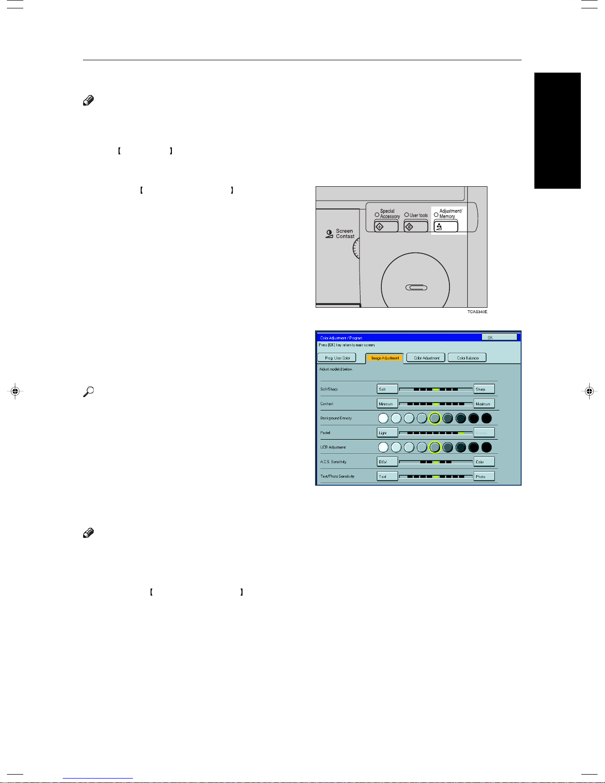
Image Adjustment
Soft/Sharp, Contrast, Background Density, and Pastel
Note
❐ Any settings you make with the Soft/Sharp, Contrast, Background Density and Pastel functions will be canceled under
the following conditions:
• The machine is automatically reset.
Clear Modes key is pressed.
• The
• The operation switch is turned off.
• The main power switch is turned off.
Press the Adjustment/Memory key.
1
Press the [Image Adjustment] key.
2
Memory
Adjustment and Color
Adjust the settings.
3
Reference
For details, ☛ see page 131.
Press the [OK] key.
4
Note
❐ If you do not press the [OK] key, you can still
make copies, but the Image Adjustment settings
you have just entered will not used. However,
any settings or featured you choose before
pressing the Adjustment/Memory key will still
apply .
133
Page 12
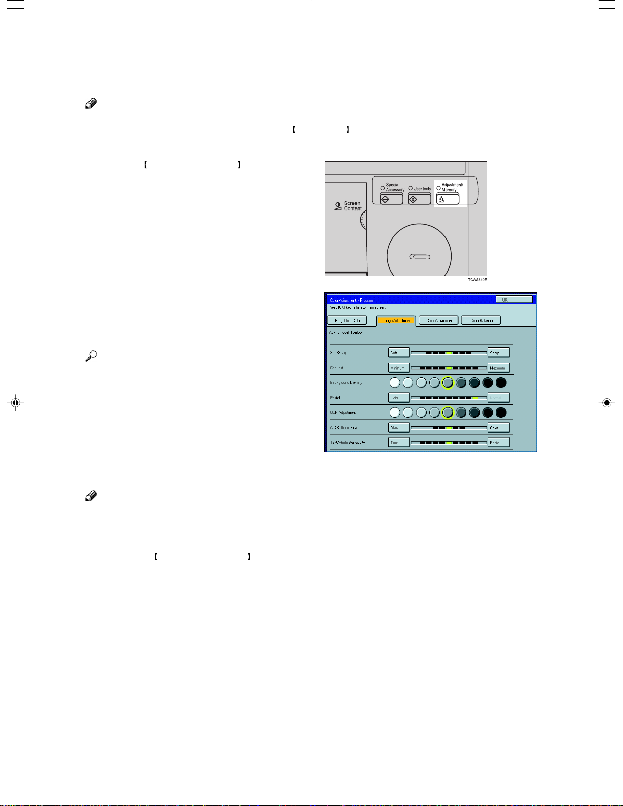
Image Adjustment
U.C.R. Adjustment, A.C.S. Sensitivity and Text/Photo Sensitivity
Note
❐ Any settings you make with the U.C.R. Adjustment, A.C.S. Sensitivity, and Text/Photo Sensitivity functions are not
cleared by turning the power off or by pressing the
them with new settings.
Press the Adjustment/Memory key.
1
Press the [Image Adjustment] key.
2
Adjust the settings.
3
Clear Modes key. They are canceled only when you overwrite
Reference
For details, ☛ see page 131.
Press the [OK] key.
4
Note
❐ If you do not press the [OK] key, you can still
make copies, but the Image Adjustment settings
you have just entered will not used. However,
any settings or featured you choose before
pressing the Adjustment/Memory key will still
apply .
134
Page 13
Program User Color—Storing User Colors
Program User Color—Storing User Colors
In addition to the base colors, you can store up to 15 customized colors into memory (User Color).
Reference
Color sample chart, ☛ see page 23.
If your machine is Edit type, you can sample the user color. ☛ See page 138.
Memory
Note
❐ There are two ways to make user colors as follows:
• Adjusting a selected base color
• Mixing colors manually with
❐ Up to 15 colors can be stored.
❐ The total percentages of the mixed colors must be 255% or less.
❐ If the total percentage of the mixed color is over 255%, the copier cannot create the color properly and the results will
appear different.
❐ If the total percentage of the mixed colors is too low, it may not be bonded to the paper properly resulting in a change
in image density.
❐ The appearance of user colors might vary slightly according to the image type you have selected (ex. Photo, Text,
etc.).
Number keys
Adjusting Colors Based on the Selected Color
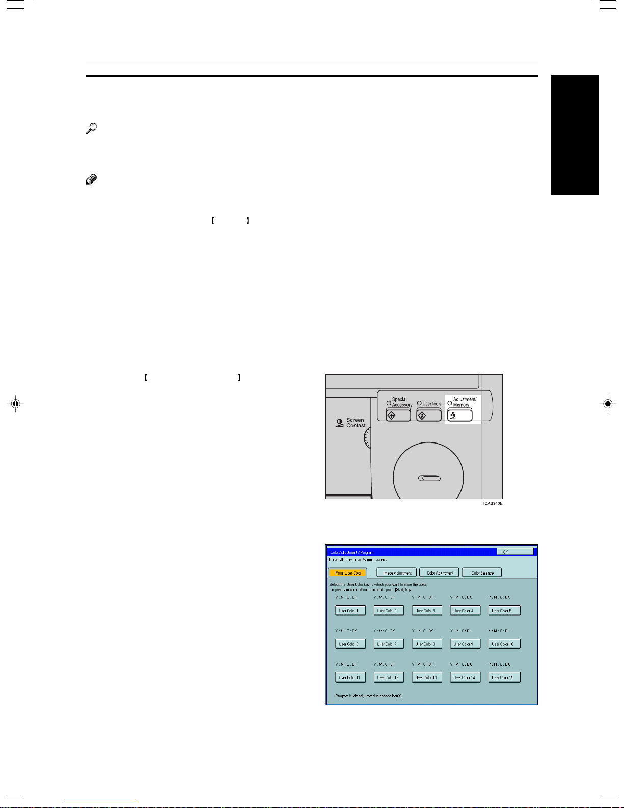
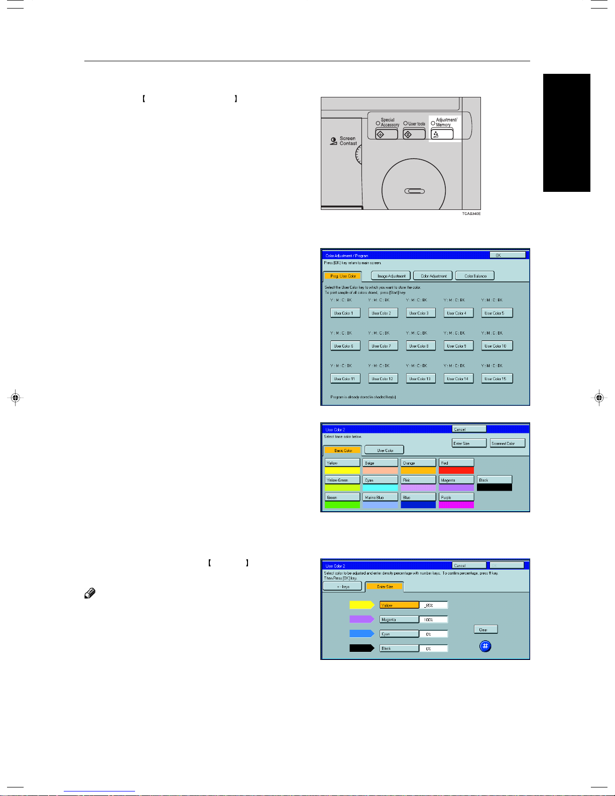
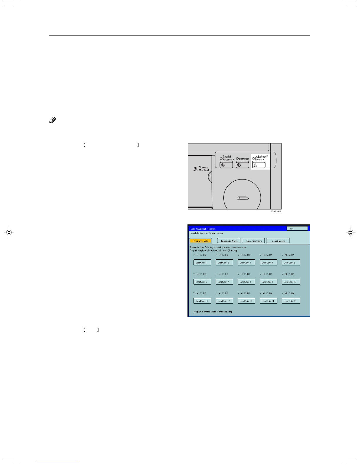
Press the Adjustment/Memory key.
1
Adjustment and Color
Press the [Prog. User Color] key.
2
Select the key you wish to store the color in.
3
135
Page 14
Program User Color—Storing User Colors
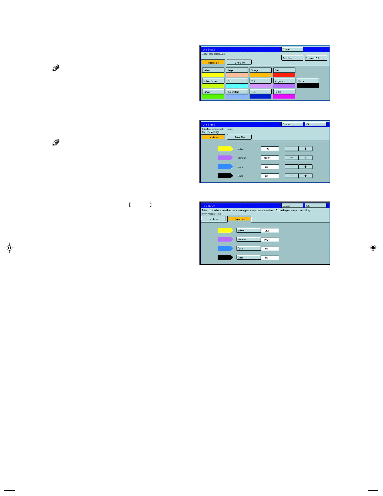
Select the base color.
4
Note
❐ If your machine is Edit type, you can scan an original
to sample it’s color. ☛ See page 128.
You can change the color density in two ways.
5
Note
❐ Increase or decrease in steps with the [+] or [-] key.
—Press the [+ - keys] key.
❐ Enter the percentage with the Number keys.—Press
the [Enter Size] key.
Repeat step 5 for each color, then press the [OK]
6
key .
Press the [OK] key.
7
136
Page 15
Mixing Colors Manually with the Number Keys
Press the Adjustment/Memory key.
1
Press the [Prog. User Color] key.
2
Select the number that you want to store the user
3
color in.
Program User Color—Storing User Colors
Memory
Adjustment and Color
Press the [Enter Size] key.
4
Select the color that you want to adjust.
5
Enter the density with the Number keys, then
6
press the [#] key.
Note
❐ To change the number, press the [Clear] key.
137
Page 16
Program User Color—Storing User Colors
Repeat steps 5 and 6 for each color then press
7
the [OK] key.
Press the [OK] key.
8
Sampling the User Color (Only for Edit Type)
You can print out a sample of User Colors to check the colors you have made.
Note
❐ The sample will be copied on a A4p, 81/2" × 11" p sheet or a A3l, 11" × 17"l sheet.
Press the Adjustment/Memory key.
1
Press the [Prog. User Color] key.
2
Press the Start key.
3
138
Page 17

Area Editing (Only f or Edit T ype)
Area Editing
(Only for Edit Type)
139
Page 18
What is Area Editing?
What is Area Editing?
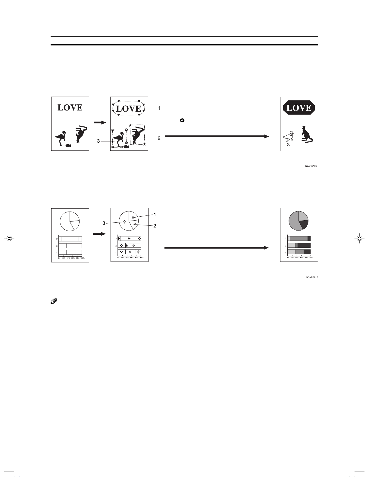
If your machine is Edit type, you can select areas of an image to be treated differently or have effects applied
to them. Some examples are shown below.
Example:
1: ♥ Group 1: Positive/Negative
2: ★ Group 2: Mirror Image
3: Group 3: Outline Image
Scan
and select Save Area
Original
(There is an area in each group.)
Designate areas
Specify modes for
each group.
1: ✜ Group 1: Color Background
2: ✴ Group 2: Color Background
3: ✧ Group 3: Color Background
Scan
Original
(There are 4 areas in each group.)
Designate areas
Specify modes for
each group.
Note
❐ “Group” means a set of areas that you want to do the same edit.
Copy
Copy
140
Page 19
How to Edit Areas
How to Edit Areas
Editing an image involves scanning it in to memory, choosing areas to edit and how those areas will be reproduced.
The basic steps are summarized below. Details are given in the rest of this section.
Enter Area Editing mode.
❐ Press the [Area Editing] key.
↓
Designate areas.
❐☛ See page 142.
↓
Select modes.
❐☛ See page 152.
↓
Specify more areas to be treated differently (optional).
❐ Repeat 3 and 4.
↓
Copy image.
❐ Press the Start key.
Area Editing
(Only for Edit Type)
141
Page 20
Designating Areas
Designating Areas
Several tools are provided for designating areas of an image.
Area Shapes
• Rectangle: Specify two points defining the opposite diagonals of a rectangle.
• Right Angle Polygon/Polygon: Specify a sequence of points defining a polygon.
• Closed Loop: If your image contains a shape outlined in black and that outline forms a closed loop, specify a point
inside the shape to designate it.
• Multi-Closed Loop: If your image contains a closed loop and that outline forms an another closed loop, specify
points inside of the closed loop to designate it.
Frame/Line
• Rectangle frame: Specify straight frames by Rectangles.
• Right Angle Polygon/Polygon frame: Specify straight frames by Right Angle Polygon/Polygon.
• Line: Specify a series of points linked together by straight lines.
Note
❐ You can designate many areas and apply the same changes to them all by placing them in the same Group.
❐ Different areas may be treated differently by placing them in different Groups.
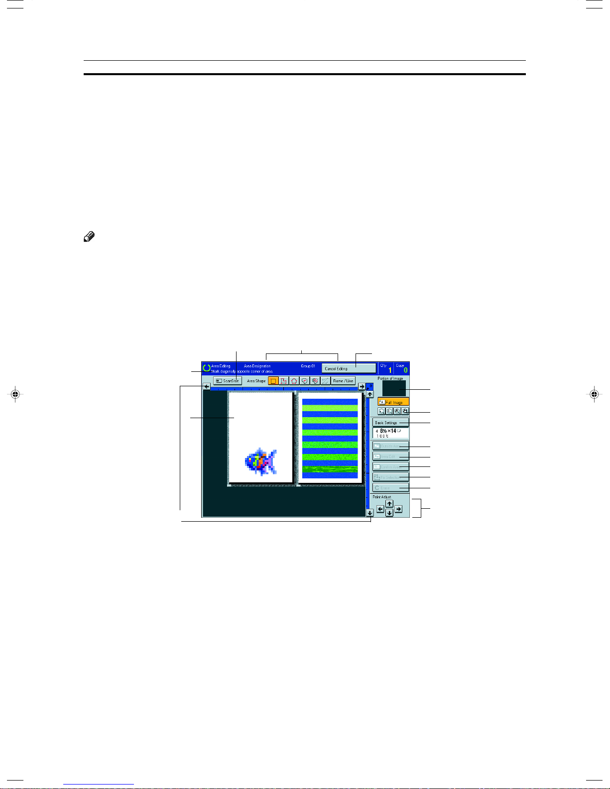
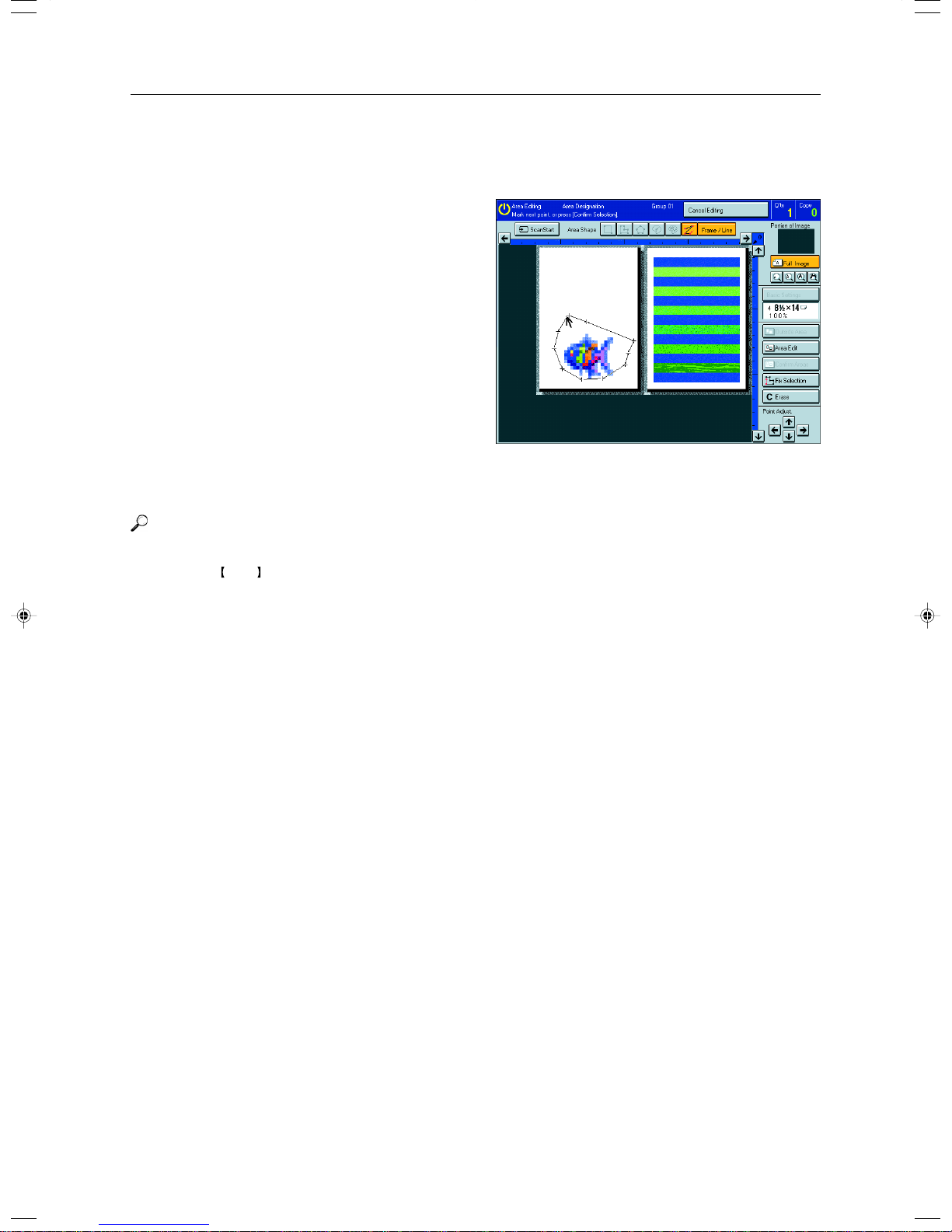
Designate Area Display
5 3
1
2
15
1. Message Area
Messages and instructions appear here.
2. Display Area
The image is displayed.
3. Area Shape/Frame/Line
Select the area shape or frame shape and line.
4. Cancel Editing
Exit area editing.
5. Scan Start
Scan in an original again.
6. Portion of Image
Shows the portion of the original that is currently being viewed or is enlarged.
4
6
7
8
9
10
11
12
13
14
142
Page 21
7. Enlarge
Enlarge 4
Enlarge by about 528%
Enlarge 3
Enlarge by about 394%
Enlarge 2
Enlarge by about 264%
Enlarge 1
Enlarge by about 200%
Full Image
Note
❐ After pressing the [Enlarge] key, mark a point in the displayed image to zoom in on.
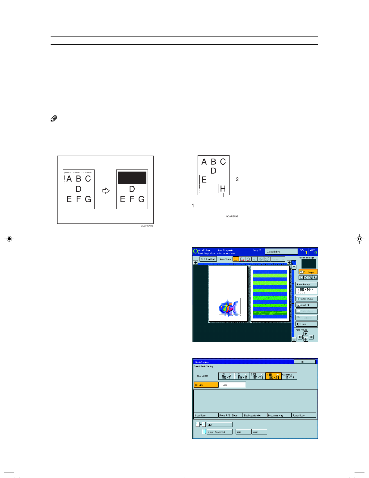
8. Basic Settings
Change the job settings for the entire image.
9. Outside Area
Set modes for outside areas.
10. Area Edit
Edit inside the area.
11. Confirm Areas
Show selected areas, modes, and groups.
12. Confirm Selection
Complete a designated area.
13. Erase
Cancel last point selected.
14. Arrow keys
Move cursor in small steps.
15. Scroll key
Move the portion of the original.
Designating Areas
Area Editing
(Only for Edit Type)
Note
❐ Do not press the touch panel display with any hard or sharp object. Always use the editor pen.
❐ When you mark a point with the editor pen, the cursor position might not be quite right. In this case, move the cursor
in small steps by pressing the arrow keys on the display.
143
Page 22
Designating Areas
Designate Area Tools
Note
❐ There are nine tools to designate areas.
Area Editing
Rectangle (☛ See page 145.)
Area Shape Right Angle Polygon (☛ See page 146.)
Polygon (☛ See page 146.)
Closed Loop (☛ See page 146.)
Multi Closed Loop (☛ See page 147.)
Rectangle frame (☛ See page 148.)
Frame/Line Right Angle Polygon frame (☛ See page 148.)
Polygon frame (☛ See page 148.)
Line (☛ See page 149.)
Note
❐ You cannot use the optional document feeder in this function.
❐ The relationships between the position of the original and the orientation of the scanned image on the display are as
follows:
Set on the
exposure glass
Display
144
Page 23
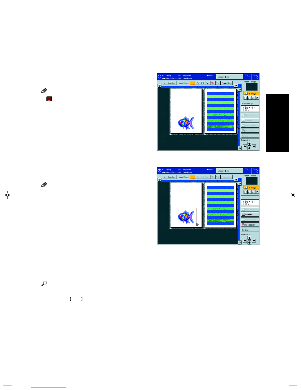
Area Shapes
Rectangle
Set your original on the exposure glass.
1
Press the [Area Editing] key.
2
Note
❐ (Rectangle) key is selected as default.
Mark the first point with the editor pen.
3
Mark the diagonally opposite corner of the area
4
you wish to select.
Designating Areas
Area Editing
(Only for Edit Type)
Note
❐ When you make a mistake, press the [Erase] key.
❐ Repeat 4 and 5 to add more rectangles.
❐ When you continue to add areas, you can select other
shapes (except Closed Loop Multi-Closed Loop, Line,
Frame).
Press the [Confirm Selection] key.
5
Press the [Area Edit] key , specify your settings,
6
then press the [OK] key.
Reference
For details, ☛ see page 152.
Press the Start key.
7
145
Page 24
Designating Areas
Right Angle Polygon and Polygon
Set your original on the exposure glass.
1
Press the [Area Editing] key.
2
Press the (R.A. Polygon) or (Polygon)
3
key.
Mark the first point with the editor pen.
4
Mark the next points.
5
Note
❐ When you use Right Angle Polygon mode, mark
points that make right angles.
After making the last point, press the [Confirm
6
Selection] key.
Press the [Area Edit] key , specify your settings,
7
then press the [OK] key.
Reference
For details, ☛ see page 152.
Press the Start key.
8
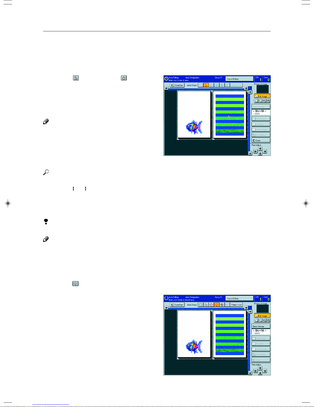
Closed Loop
Limitation
❐ If you specify an area with Closed Loop, you cannot specify any additional areas with other selection tools.
Note
❐ When you color areas with the Closed Loop, the area boundary may shift depending on the image.
Set your original on the exposure glass.
1
Press the [Area Editing] key.
2
Press the (Closed Loop) key.
3
Touch on a point inside a closed loop.
4
146
Page 25
Designating Areas
Press the [Fix Selection] key.
5
Press the [Area Edit] key , specify your settings,
6
then press the [OK] key.
Reference
For details, ☛ see page 152.
Press the Start key.
7
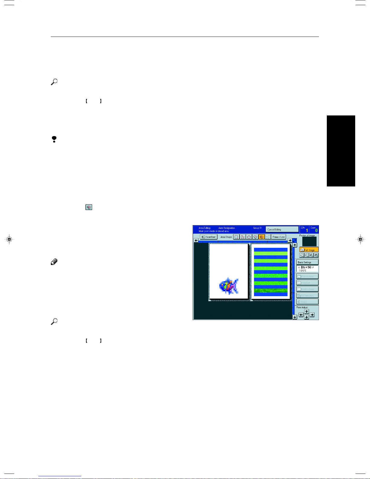
Multi-Closed Loop
Limitation
❐ If you specify an area with Multi-Closed Loop, you cannot specify any additional areas with other selection tools.
Set your original on the exposure glass.
1
Press the [Area Editing] key.
2
Press the (Multi-Closed loop) key.
3
Press on a point inside the exterior area you wish
4
to specify.
Press on a point inside the interior area you wish
5
to treat differently.
Note
❐ Be sure to select a point inside of the exterior area
you wish to define.
Press the [Confirm Selection] key.
6
Press the [Area Edit] key , specify your settings,
7
then press the [OK] key.
Reference
For details, ☛ see page 152.
Press the Start key.
8
Area Editing
(Only for Edit Type)
147
Page 26
Designating Areas
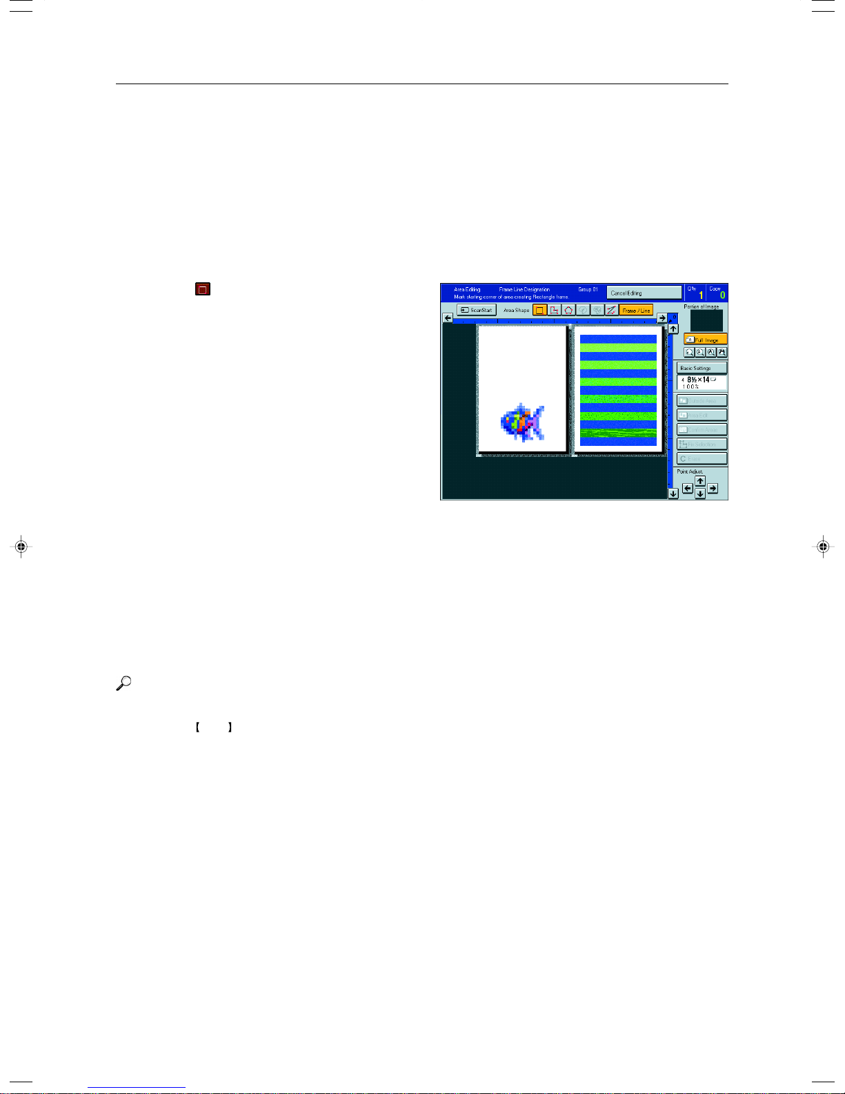
Frame/Line
Rectangle frame
Set your original on the exposure glass.
1
Press the [Area Editing] key.
2
Press the [Frame/Line] key.
3
Press the (Rectangle) key.
4
Mark the first point with the editor pen.
5
Mark the diagonally opposite corner of the area
6
you wish to select.
Press the [Confirm Selection] key.
7
Press the [Area Edit] key , specify your settings,
8
then press the [OK] key.
Reference
For details, ☛ see page 152.
Press the Start key.
9
Right Angle Polygon frame and Polygon frame
Set your original on the exposure glass.
1
Press the [Area Editing] key.
2
Press the [Frame/Line] key.
3
148
Page 27
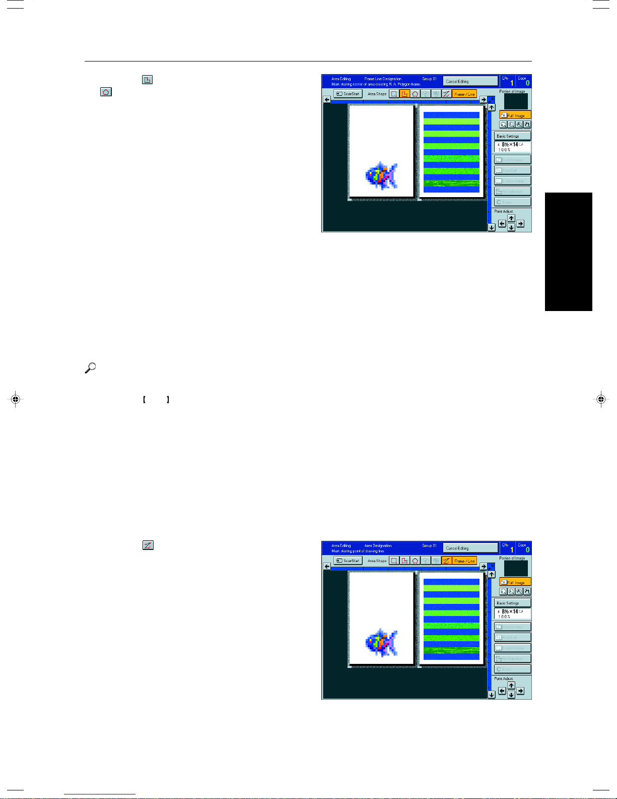
Press the (Right Angle Polygon) key or the
4
(Polygon) key.
Mark the first point with the editor pen.
5
Mark the next points.
6
After making the last point, press the [Confirm
7
Selection] key.
Press the [Area Edit] key , specify your settings,
8
then press the [OK] key.
Designating Areas
Area Editing
(Only for Edit Type)
Reference
For details, ☛ see page 152.
Press the Start key.
9
Line
Set your original on the exposure glass.
1
Press the [Area Editing] key.
2
Press the [Frame/Line] key.
3
Press the (Line) key.
4
149
Page 28
Designating Areas
Mark the first point with the editor pen.
5
Mark the next points.
6
After marking the last point, press the [Confirm
7
Selection] key.
Press the [Area Edit] key , specify your settings,
8
then press the [OK] key.
Reference
For details, ☛ see page 152.
Press the Start key.
9
150
Page 29

Designating Areas
Notes for Designating Areas
The number of the points, areas, and groups that can be designated
Note
❐ Maximum number of points: 500
❐ In Right Angle Polygon mode, Polygon mode, or Line mode, the maximum number of points for one area is 30.
❐ The number of areas that can be designated is as follows:
• Rectangle mode: maximum 250 areas
• Right Angle Polygon mode, Polygon mode, Line mode: 500 points maximum. For example, if 10 points are desig-
nated for each area, the maximum number of areas that can be designated is 50.
• Closed Loop mode, Multi-Closed Loop mode: maximum 500 areas
❐ Maximum number of groups: 20
(“Group” means a set of areas that you want to do same editions.)
Note
❐ Do not designate an area or line which overlaps part of another area or line. If an area overlaps another one, the job
settings specified last will be applied to the overlapped portion or those areas might not be copied.
❐ However, areas containing areas (see below) are permitted. Designate starting with the outermost area.
1
2
GCAREA4E
These operations are available, however, under the following conditions:
• When designating areas with Closed Loop mode, Multi-closed Loop or Line/Frame mode.
❐ If you mark a line and it overlaps another line you have previously marked, the last point you marked will be canceled
automatically.
❐ If you designate an area in Right Angle Polygon mode, make sure to mark points that make right angles. If you mark a
point which does not match, the editor will automatically correct it to make a right angle.
❐ If you want to designate a triangular area, use Polygon mode.
❐ In Closed Loop mode or Multi-Closed Loop mode, the machine might not detect a closed loop area or multi-closed loop
area completely under the following conditions:
• The outline is not completely closed, it is too light to detect, or the thickness is uneven.
• The outline is thinner than 0.3mm.
• The outline is not black.
• The space between two closed loop outlines is less than 1mm.
• The closed loop can be up to 2 meters long.
• The area enclosed by the outline is not white.
❐ The more areas you designate, the more time copying will take.
❐ If you erase an area, group, or job setting, it is cleared from the display. However, the points are still stored in memory
and are not cleared until you exit Area Editing. This affects the maximum number of areas you can designate.
❐ Closed Loop mode Multi-Closed Loop mode and Frame/Line mode cannot be used with Rectangle mode, Right Angle
Polygon mode, and Polygon mode for one group at a time.
❐ If you need to align areas precisely, you can have a grid shown on the enlarged display. The grid spacing matches the
scale of the display.
Area Editing
(Only for Edit Type)
151
Page 30

Selecting Modes for Designated Areas
Selecting Modes for Designated Areas
Reference
The available modes for area editing depend on the area shape. ☛ See page 164.
For functions that cannot be used together in area editing, ☛ see page 164.
More than one mode can be set for designated area, however, there are some limitations, ☛ see page 164. And up to 7
patterns of modes can be set together.
Note
❐ Up to 20 groups of multiple areas can be edited. All the areas should belong to groups 1 ~ 20.
You can select up to seven job patterns for at most 20 groups. After you have set seven patterns, the copier will only
allow you to choose the pattern of a previous group.
If you change the settings for one group, it will change the settings for all other groups with the same job pattern.
However, if you have set a Paint, Color Background, or Frame/ Line, changing the color in one group will not affect
other groups. (Up to 15 colors can be selected.)
❐ The modes that can be set for inside areas as follows:
• Color/Image Adjustment: Image Density, Color Mode, Original Type, Image Adjustment, Color Adjustment, Color
Balance Adjustment
• Color Creation: Color Conversion, Color Erase, Color Background, Paint, Type Mask
• Image Creation: Outline Image, Shadow Image, Slanted Image, Mirror Image, Positive/Negative
Note
❐ The editing functions available when specifying area with Frame/Line mode are Width and Color.
❐ Color/Image Adjustment’s default setting:
• Image Density - Manual Image Density
• Color Mode - Black
• Original Type - Text
❐ You can change the default settings. ☛ See page 187.
❐ Depending on the shapes of the areas, coloring or deleting near the outlines of the areas might not do well, or the
outlines might become uneven.
❐ The way to set modes is basically the same as for the entire image. For details, refer to each page.
• To fill an area with a selected color, select the Paint.
• Image Density ☛ See page 39.
• Original Type ☛ See page 44.
• Color Adjustment ☛ See page 131.
• Color Conversion ☛ See page 85.
• Type Mask ☛ See page 89.
• Color Background ☛ See page 88.
• Outline Image ☛ See page 91.
• Slanted Image ☛ See page 95.
• Positive/Negative ☛ See page 101.
• Color Mode ☛ See page 40.
• Image Adjustment ☛ See page 132.
• Color Balance Adjustment ☛ See page 124.
• Color Erase ☛ See page 87.
• Shadow Image ☛ See page 92.
• Mirror Image ☛ See page 96.
• Save Area ☛ See page 154.
• Changing Job Settings for the Entire Image
☛ See page 158.
• Change Modes ☛ See page 159.
• Adding Areas ☛ See page 160.
• Erasing a Group ☛ See page 162.
Area Shapes
Basic modes
Designate the areas you wish to modify.
1
Note
❐ For designating areas, ☛ see page 145.
152
Page 31

Press the [Area Edit] key.
2
Press the [Color/Image], [Color Creation] or
3
[Image Creation] key.
Set the desired modes.
4
Note
❐ Color/Image, ☛ see page 121.
❐ Color Creation, ☛ see page 85.
❐ Image Creation, ☛ see page 91.
Selecting Modes for Designated Areas
Area Editing
(Only for Edit Type)
Press the [OK] key.
5
Press the [Start] key.
6
Delete Area—Erasing a Part of the Image
This function blanks out designated areas.
1: Designated area
Note
❐ When you select Delete Area mode, previously selected modes are canceled.
Designate the areas you wish to modify.
1
153
Page 32

Selecting Modes for Designated Areas
Press the [Area Edit] key.
2
Note
❐ For designating areas, ☛ see page 152.
Press the [Delete Area] key.
3
Press the [OK] key.
4
Press the Start key.
5
Save Area—Blanking out Part of the Image
This function blanks out all areas except those designated.
1: Designated area
Note
❐ When you select Save Area mode, previously selected modes are canceled.
Designate the areas you wish to modify.
1
Note
❐ For designating areas, ☛ see page 145.
Press the [Area Edit] key.
2
154
Page 33

Press the [Save Area] key.
3
Press the [OK] key.
4
Press the Start key.
5
Frame/Line
Editing color and widths
Note
❐ Frame/Line mode do not work with other modes.
❐ Frame/Line widths:
Metric version: 0.25 ~ 2.0mm (in 0.25mm steps)
Inch version: 0.01" ~ 0.08" (in 0.01" steps)
❐ The frame and line width might be uneven depend-
ing on the angle of the line.
Selecting Modes for Designated Areas
Area Editing
(Only for Edit Type)
Designate the areas you wish to modify.
1
Note
❐ For designating areas, ☛ see page 145.
Press the [Area Edit] key.
2
Select the color and widths.
3
Press the [OK] key.
4
155
Page 34

Selecting Modes for Outside Designated Areas
Selecting Modes for Outside Designated Areas
Reference
The available modes for area editing depend on the area shape. ☛ See page 164.
For functions that cannot be used together in area editing, ☛ see page 164.
More than one mode can be set, however, there are some limitations, ☛ see page 164.
The modes that can be set for outside areas as follows:
• Color/Image Adjustment: Image Density, Color Mode, Original Type, Image Adjustment, Color Adjustment, Color
Balance Adjustment
• Color Creation: Color Conversion, Color Erase, Color Background, Paint, Type Mask
• Image Creation: Outline Image, Shadow Image, Positive/Negative
Note
❐ Color/Image Adjustment’s default setting:
• Copy Image Density Adjustment - Manual Image Density
• Color Mode - Black
• The Original Image Type - Photo/Text
❐ You can change the default settings. ☛ See page 187.
❐ The way to set modes is basically the same as for the entire image. For details, refer to each page.
• To fill an area with a selected color, select the Paint. • Positive/Negative ☛ See page 101.
• Image Density ☛ See page 39. • Color Mode ☛ See page 40.
• Original Type ☛ See page 44. • Image Adjustment ☛ See page 132.
• Color Adjustment ☛ See page 131. • Color Balance Adjustment ☛ See page 124.
• Color Conversion ☛ See page 85. • Color Erase ☛ See page 87.
• Color Background ☛ See page 88. • Shadow Image ☛ See page 92.
• Type Mask ☛ See page 89. • Save Area ☛ See page 154.
• Outline Image ☛ See page 91.
Area Shapes
Basic modes
Designate the areas you wish to modify.
1
Note
❐ For designating areas, ☛ see page 145.
Press the [Area Edit] key.
2
Press the [Color/Image], [Color Creation] or
3
[Image Creation] key.
156
Page 35

Set the desired modes.
4
Note
❐ Color/Image, ☛ see page 121.
❐ Color Creation, ☛ see page 85.
❐ Image Creation, ☛ see page 91.
❐ Basic Settings, ☛ see page 158.
Press the [OK] key.
5
Press the [Start] key.
6
Selecting Modes for Outside Designated Areas
Save Area
Designate the areas you wish to modify.
1
Note
For designating areas, ☛ see page 145.
Press the [Area Edit] or [Outside Area] key.
2
Press the [Save Area] key.
3
Press the [Start] key.
4
Area Editing
(Only for Edit Type)
157
Page 36
Changing Job Settings for the Entire Image
Changing Job Settings for the Entire Image
You can change job settings for the entire image during area editing.
❐ The job settings that can be changed are as follows:
• Paper Select, ☛ see page 47.
• Reduce/Enlarge (Preset R/E, Zoom, Size Magnification, Directional Magnification, Poster Mode), ☛ see page 59.
• Shift, ☛ see page 77.
• Margin Adjustment, ☛ see page 78.
• Sort/Stack/Staple (Option), ☛ see page 102.
Note
❐ Regarding functions that cannot be used together in area editing, ☛ see page 164.
❐ When you set Shift and designate more than one area in this mode, the minimum size rectangle that includes all the
designated areas is shifted as follows:
Press the [Basic Settings] key.
1
Change the job settings.
2
Press the [OK] key.
3
1: Designated area
2: Area that will be shifted
158
Page 37

Checking and Changing Areas
Checking and Changing Areas
Use this function to check the areas you have selected and the modes you have chosen for each area.
You can:
• Change the modes for an area/Group
• Add an area to a Group
• Erase an area
• Erase a Group
Note
❐ Note that even if you erase a job setting, a group, or an area, they still consume memory until you exit Area Editing.
Change Modes
Press the [Confirm Areas] key.
1
Note
❐ All designated areas are displayed.
Area Editing
(Only for Edit Type)
Select an area or a group.
2
Note
❐ Areas in this group are highlighted.
Press the [Change Setting] key.
3
159
Page 38

Checking and Changing Areas
Change the modes, then press the [OK] key.
4
Note
❐ Color/Image, ☛ see page 121.
❐ Color Creation, ☛ see page 85.
❐ Image Creation, ☛ see page 91.
❐ Color Adjustment, ☛ see page 130.
❐ Basic Settings, ☛ see page 158.
❐ Delete Area, ☛ see page 153.
❐ Save Area, ☛ see page 154.
Press the [Previous] key.
5
Adding Areas
Press the [Confirm Areas] key.
1
Note
❐ The all designated areas are displayed.
Select an area or a group.
2
Note
❐ Areas in this group are highlighted.
Press the [Add Area] key.
3
Select the area shape.
4
160
Page 39

Designate areas, then press the [Confirm Ar-
5
eas] key.
Note
❐ For designating areas, ☛ see page 145.
Press the [Previous] key.
6
Erasing an Area
Press the [Confirm Areas] key.
1
Note
❐ All designated areas are displayed.
Checking and Changing Areas
Area Editing
(Only for Edit Type)
Select an area that you want to cancel.
2
Press the [Delete Area] key.
3
Press the [Yes] key.
4
Press the [Previous] key.
5
161
Page 40

Checking and Changing Areas
Erasing a Group
Press the [Confirm Areas] key.
1
Note
❐ All designated areas are displayed.
Select a group that you want to cancel.
2
Note
❐ Areas in this group are highlighted.
Press the [Delete Group] key.
3
Press the [Yes] key.
4
Press the [Previous] key.
5
162
Page 41

Press the [Cancel Editing] key.
1
Exiting Area Editing
Exiting Area Editing
Press the [Yes] key.
2
Area Editing
(Only for Edit Type)
163
Page 42

Combination Chart for Area Editing
Combination Chart for Area Editing
q Functions available for designated areas.
w Functions available for areas outside designated areas.
e Functions that can be selected together in an area.
r Functions available with each shape.
t Functions available for the entire image.
e
Newly selected mode
Density Color Mode Color Creation Image Creation
qw
Auto Image Density
Manual Image Density
Full Color
Black & White
Single Color
Twin Color
Original Image Type Selection
Type Mask
Color Conversion
Color Erase
Color Background
Paint
Outline Image
Shadow Image
Slanted Image
Mirror Image
Image
Density
Color Mode
Original Image Type Selection ★✩✩✩✩✩✩✩ ➞✩✩✩➞✩✩✩✩✩
Color
Creation
Image
Creation
Image
Adjustment
Auto Image Density
Manual Image Density ✩✩✩ ✩✩✩✩✩➞✩✩✩➞✩✩✩✩✩
Full Color ★✩ ✗ ✩ ➞➞➞✩✩✩✩✩➞✩✩✩✩✩
Black & White ★✩✩✩➞ ➞➞✩➞✩✩✩➞✩✩✩✩✩
Single Color ★✩✩✩➞➞ ➞✩➞✩✩✩➞✩✩✩✩✩
Twin Color ★✩✩✩➞➞➞ ✩➞✩✩✩➞✗✩✩✩✩
Type Mask ★✩✩✗✩✗✗✗✩ ➞➞➞➞✗✩✩✩✩
Color Conversion ★✩✩✩✩✗ ✗ ✗✩➞ ✩✩➞ ✗✩✩✩✩
Color Erase ★✩✩✩✩✩✩✗✩➞✩ ✩➞✗✩✩✩✩
Color Background ★✩✩✩✩✩✩✩✩➞✩✩ ➞✗✩✩✩✩
Paint ★✩ ✗ ✗ ✗ ✗ ✗ ✗ ✗➞➞➞➞ ✗ ✗ ✗✩✩
Outline Image ★✩✩✩✩✩✩✗ ✗ ✗ ✗ ✗ ✗ ✗ ✩✩✩✩
Shadow Image ★✩✩✩✩✩✩✩✩✩✩✩✩✗✩ ✩✩✩
Slanted Image ★✗✩✩✩✩✩✩✩✩✩✩✩✗✩✩ ✩✩
Mirror Image ★✗✩✩✩✩✩✩✩✩✩✩✩➞✩✩✩ ✩
Positive/Negative ★✩✩✩✩✩✩✩✩✩✩✩✩✩✩✩✩✩
Soft/Sharp ★✩✩✩✩✩✩✩✩➞✩✩✩➞➞✩✩✩✩
Contrast ★✩✩✩✩✩✩✩✩✩✩✩✩✩✩✩✩✩✩
Background Density ★✩✩✩✩✩✩✩✩➞✩✩✩✩➞✩✩✩✩
Pastel ★✩✩✩✩✩✩✩✩➞✩✩✩✩➞✩✩✩✩
U.C.R Adjustment ★✩✩✩✩✩✩✩✩✩✩✩✩✩✩✩✩✩✩
Text/Photo Sensitivity ✗✩✩✩✩✩✩✩✩✩✩✩✩✩✩✩✩✩✩
Color Adjustment ★✩✩✩✩➞➞➞✩➞✩✩✩➞➞✩✩✩✩
Color Balance Adjustment ★✩✩✩✩✩✩✩✩➞✩✩✩✩➞✩✩✩✩
Save Area ✩✩✩✩✩✩✩✩✩✩✩✩✩✩✩✩✩✩✩
Delete Area ✩✗✗✗✗✗✗✗✗✗✗✗✗✗✗✗✗✗✗
Preset Reduce/Enlarge / Zoom ✗✗
Size Magnification ✗✗
Directional Magnification ✗✗
Poster Mode ✗✗
Auto Reduce/Enlarge ✗✗
Centering/Cornering, Margin Adjustment
Center Erase, Center/Border Erase, Border Erase
Duplex/Combine ✗✗
Auto Paper Select ✗✗
Bypass Tray Copying ✗✗
Program ✗✗
Interrupt Copying ✗✗
Sort/Stack/Staple (Option) ✗✗
★✩ ✩➞✩✩✩✩✩✩✩✩✩✩✩✩✩✩
✗✗
✗✗
Positive/Negative
164
Page 43

Combination Chart for Area Editing
✩ : These modes can be used together.
★ : These modes can be used together with some limitations.
➞ : The original mode is overridden and only the newly selected mode is active.
✗ : These modes cannot be used together.
e
Newly selected mode
Image Adjustment
Soft/Sharp
Contrast
Background Density
Pastel
U.S.R. Adjustment
Text/Photo Sensitivity
Color Adjustment
Color Balance Adjustment
Save Area
Delete Area
Rectangle
Image
Density
Color Mode
Original Image Type Selection ✩✩✩✩✩✩✩✩✩➞✩✩✩✩✩––––
Color
Creation
Image
Creation
Image
Adjustment
Auto Image Density
Manual Image Density ✩✩✩✩✩✩✩✩✩➞✩✩✩✩✩––––
Full Color ✩✩✩✩✩✩✩✩✩➞✩✩✩✩✩––– –
Black & White ✩✩✩✩✩✩ ✗✩✩➞✩✩✩✩✩––––
Single Color ✩✩✩✩✩✩✗ ✩✩➞✩✩✩✩✩––– –
Twin Color ✩✩✩✩✩✩ ✗✩✩➞✩✩✩✩✩––––
Type Mask ✗✩✗✗✩✗✗✗✩➞✩✩✩✗✗––––
Color Conversion ✩✩✩✩✩✩✩✩✩➞✩✩✩✗ ✗––––
Color Erase ✩✩✩✩✩✩✩✩✩➞✩✩✩✗ ✗––––
Color Background ✩✩✩✩✩✩✩✩✩➞✩✩✩✩✩––– –
Paint ✗✩✗✩✩✗✗✩✩➞✩✩✩✩✩––––
Outline Image ✗✩✗✗✩✩✗✗✩➞✩✩✩✗✗––––
Shadow Image ✩✩✩✩✩✩✩✩✩➞✩✩✩✗ ✗––––
Slanted Image ✩✩✩✩✩✩✩✩✩➞✩✗ ✗✗ ✗––––
Mirror Image ✩✩✩✩✩✩✩✩✩➞✩✗ ✗ ✗ ✗ ––– –
Positive/Negative ✩✩✩✩✩✩✩✩✩➞✩✩✩✗ ✗ ––––
Soft/Sharp ✩✩✩✩✩✩✩✩➞✩✩✩✩✩––––
Contrast ✩ ✩✩✩✩✩✩✩➞✩✩✩✩ ✩––– –
Background Density ✩✩ ✩✩✩✩✩✩➞✩✩✩✩ ✩––– –
Pastel ✩✩✩ ✩✩✩✩✩➞✩✩✩✩ ✩––– –
U.C.R Adjustment ✩✩✩✩ ✩✩✩✩➞✩✩✩✩ ✩––– –
Text/Photo Sensitivity ✩✩✩✩✩ ✩✩✩➞✩✩✩✩ ✩ ––––
Color Adjustment ✩✩✩✩✩✩ ✩✩➞✩✩✩✩✩––––
Color Balance Adjustment ✩✩✩✩✩✩✩ ✩➞✩✩✩✩✩––––
Save Area ✩✩✩✩✩✩✩✩ ✩✗✗ ✗✗ ✗ ––––
Delete Area ✗✗✗✗✗✗✗✗✗ ✩✩✩✩✩––––
Preset Reduce/Enlarge / Zoom ✩
Size Magnification ✩
Directional Size Magnification ✩
Poster Mode ✩
Auto Reduce/Enlarge ✗
Centering/Cornering, Margin Adjustment
Center Erase, Center/Border Erase, Border Erase
Duplex/Combine ✗
Auto Paper Select ✗
Bypass Tray Copying ✩
Program ✩
Interrupt Copying ✗
Sort/Stack/Staple (Option) ✩
✩✩✩✩✩✩✩✩✩➞✩✩✩✩✩––––
Right Angle Polygon
r
Polygon
Closed Loop
Multi Closed Loop
Line
Rectangle frame
Right Angle Polygon frame
Polygon frame
Area Editing
(Only for Edit Type)
t
✩
✗
165
Page 44

166
Page 45
What to do if Something Goes
Wrong
Goes Wrong
What to do if Something
167
Page 46

If Your Machine Does not Operate as You want
If Your Machine Does not Operate as You Want
Check the following:
Condition
Action
Nothing happens when the
operation switch is turned
on.
BPaper tray is empty.
DToner container is almost
empty. Or toner container is
empty.
MDoors/covers are open.
xMisfeed occurs.
dThe machine instructs you
to add staples.
The machine instructs you to
enter your user code.
The Energy Saver indicator
is on.
Misfeeds occur frequently.
Is the main power switch turned on?
Turn on the main power switch.
Load paper. ☛ See page 172.
Add toner. ☛ See page 175.
Close the doors/covers.
Remove misfed paper. ☛ See page 177.
Add staples. ☛ See page 179.
The machine is set for User Code mode. Enter your user code. ☛ See page 196.
Your machine is under the energy saver condition.
Press the Energy Saver key. ☛ See page 55.
Is the right kind of paper in the paper tray?
Paper size and weight must be within the specifications for this machine.
Is folded, wrinkled, damp, or curled paper in the paper tray?
Always use dry, undamaged paper.
Is the paper properly set in the paper tray?
Always load paper correctly.
Staples do not come out at
all.
E or H or L is lit
The machine cannot detect
the original size.
The machine instructs you to
check the original direction.
The machine instructs you to
check paper size.
The machine cannot sort
this size paper.
The machine cannot stack
this size paper.
Are there any pieces of misfed paper or other foreign objects in the machine?
Make sure that the paper path is completely clear of paper and other material after a
misfeed.
There are jammed staples in the stapler.
Remove the jammed staples. ☛ See page 181.
After loading a new staple cartridge, staples might not be ejected the first few times
you try to use the stapler.
Contact your service representative.
Set custom size original on the exposure glass.
Input the both horizontal and vertical sizes of the custom original. ☛ See page 50.
Select paper manually, not in Auto Paper Select mode.
Do not use Auto Reduce/Enlarge mode.
Set your originals.
Set the original in the same direction as the copy paper.
Select the proper paper size.
Select the proper paper size that can be used in Sort mode. ☛ See page 102.
Select the proper paper size that can be used in Stack mode. ☛ See page 103.
168
Page 47

If Your Machine Does not Operate as You want
Condition
You cannot enter the desired
copy set number.
The machine instructs you to
set the duplex tray.
The machine instructs you to
wait.
The panel display is off.
❐ If you cannot correct the problem by taking the above actions, please contact your service representative.
Action
You can change the maximum copy quantity that you can make at a time. ☛ See
page 195.
Reset the duplex tray correctly. ☛ See page 2.
Wait for the machine to warm-up.
Press the
Turn on the operation switch.
Adjust the Screen Contrast. ☛ See page 5.
Energy Saver key to cancel Energy Saver mode.
Goes Wrong
What to do if Something
169
Page 48

If You Cannot Make Copies as You Want
If You Cannot Make Copies as You Want
Problem
Copies appear dirty.
The reverse side of an original image
is copied.
A shadow is copied when copying a
pasted original.
Cause
The image density is too dark.
The exposure glass (platen glass) or
document feeder belt is dirty.
The image density is too dark.
The image density is too dark.
Action
Adjust the image density.
☛ See page 39.
Adjust the background density.
☛ See page 132.
Clean them. ☛ See page 200.
Adjust the image density.
☛ See page 39.
If you select Black & White Copy mode
or Single Color mode, place a black
paper in the backside of the original
and select Auto Image Density mode.
Lighten the background density.
☛ See page 132.
Adjust the image density.
☛ See page 39.
Adjust the background density.
☛ See page 132.
Set the original in a different direction.
Put mending tape on the bound part.
Copies are too light.
Copy image is not clear.
The same copy area is dirty whenever
making copies.
When using Enlarge mode, shadows
appear on the margins of copies.
Copies are blank or parts of the image are not copied.
The original has a low contrast image.
The image density is too light.
Damp or rough grain paper is used
The original image type is not selected
properly.
The exposure glass (platen glass) or
document feeder belt is dirty.
Shadows may appear because the
whole surface area of the exposure
glass was scanned in.
The original is not set correctly.
An improper paper size is selected.
The selected reproduction ratio does
not match the paper size.
Adjust the image density.
☛ See page 39.
Use dry paper without rough grain.
Select the proper original image type.
☛ See page 44.
Adjust the sharpness of the image with
the Soft/Sharp function.
☛ See page 132.
Clean them. ☛ See page 200.
Select the Border Erase mode.
☛ See page 81.
Set the originals correctly.
☛ See page 31, 32 or 33.
Select the proper paper size.
Select the proper reproduction ratio.
170
Page 49

If You Cannot Make Copies as You Want
Problem
A moire pattern is produced on copies as shown in the illustration.
R R
Color tone of copies is different from
that of originals.
Color tone of copies is completely different from that of originals.
Letter parts and photo parts of an
original are not separated correctly.
Cause
The Text mode is selected.
The line images of the original might
be overlapped each other.
The color balance is not set properly.
Unsuitable color setting.
An original has screen letters or low
density letters.
An original has a high contrast photo.
An original has a photo having se-
quence thin lines with regular thin
spaces.
Action
Select Auto Original T ype Select mode
or Photo mode. ☛ See page 44.
Place the original on the exposure
glass (platen glass) at a slight angle.
Adjust the sharpness of the image.
☛ See page 132.
Adjust the Color Balance.
☛ See page 124.
Perform the Auto Color Calibration
(A.C.C.).
☛ See page 198.
Perform Auto Color Calibration
(A.C.C.). ☛ See page 198.
If you cannot correct the problem by
performing Auto Color Calibration,
contact your service representative.
Adjust the Text/Photo Sensitivity to a
“Text” level. ☛ See page 132.
Adjust the Text/Photo Sensitivity to a
“Photo” level. ☛ See page 132.
Color parts of an original are copied
in black in Auto Color Select mode.
Non-color parts of an original are copied in color in Auto Color Select mode.
A copy image is blurred.
In Margin Adjustment mode, parts of
the original image are not copied.
In Repeat Image mode, the original
image is not copied repeatedly.
❐ If you cannot correct the problem by taking the above actions, please contact your service representative.
There are small or thin color parts.
The machine might detect some black
and white screen images (such as
from newspaper) as a full color original.
The image density is too light.
An improper kind of paper is set.
Toner is running out.
The margin is set too wide.
An improper reproduction ratio is selected.
Adjust the A.C.S. Sensitivity to a “Full
color” level. ☛ See page 132.
Select Black & White mode.
☛ See page 40.
Adjust the A.C.S. Sensitivity to a
“B&W” level.
☛ See page 132.
Adjust the image density.
☛ See page 39.
Set the right kind of paper in the paper tray.
Note
❐ Copies might be blurred if you copy
onto rough grain, coated, or damp
paper.
Add toner. ☛ See page 175.
Set the narrow margin with the user
tools. ☛ See page 195.
Select the proper reproduction ratio.
Goes Wrong
What to do if Something
171
Page 50

BLoading Paper
BLoading Paper
Reference
Regarding paper sizes that can be set, ☛ see page 238.
Note
❐ If you want to change the paper size, ☛ see page 184.
Non-recommended Paper for Paper Trays
❐ Folded, curled, creased, or damaged paper
❐ Torn paper
❐ Perforated paper
❐ Paper with conductive or low electrical resistance coating such as carbon or silver coating
❐ Thermal paper, art paper
❐ Thin paper that has low stiffness
❐ Damp paper
❐ Wavy paper
❐ Stapled paper
❐ Translucent paper
❐ OHP transparencies
Note
❐ Load paper with the side you wish to copy onto face-down in the paper trays. If copies are curled, try turning the copy
paper over in the tray. If there is no improvement, change to copy paper with less curl.
❐ Correct curls in copy paper before loading.
❐ Fan copy paper to get air between the sheets before loading.
❐ When making 2-sided copies, do not load paper in the paper tray to copy on the reverse side. Use the bypass tray.
☛ See page 52.
Loading Paper in the Paper Tray
Pull out the paper tray until it stops.
1
While pressing the lock lever, open the side
2
fences.
172
Page 51

Square the paper and set it in the tray.
3
Note
❐ Do not stack paper over the limit mark.
❐ Make sure that the leading corners of the paper are
under the corners.
Reinstall the side fences.
4
Push the paper tray in until it stops.
5
BLoading Paper
Goes Wrong
What to do if Something
173
Page 52

BLoading Paper
Loading Paper in the Large Capacity Tray
Press the Down key if it is not lit.
1
Note
❐ The key blinks while the bottom plate is moving down.
1: Down key
When the key stops blinking and lights up, open
2
the top cover.
Note
❐ Make sure no paper sheet is involved in the feeding
part of the Large Capacity Tray. Remove the sheet,
if any.
Place the paper in the tray along the edge on
3
the left.
Note
❐ The Tray contains up to 1,500 sheets.
Close the top cover.
4
174
Page 53
DAdding Toner
DAdding Toner
There are four kinds of toner (Cyan, Magenta, Yellow, and Black). When a is lit, it is time to add toner.
R
WARNING:
• Do not incinerate used toner or toner containers. T oner dust might ignite when exposed to
s
R
CAUTION:
R
R
CAUTION:
R
Note
❐ If you use toner other than that recommended, a fault might occur.
❐ When adding toner, do not turn off the operation switch. If you do, your settings are cleared.
❐ Always add toner after the machine instructs you to add toner.
❐ Do not use used toner. This will damage the machine.
❐ Be sure to add the correct color toner.
❐ You can still make about 20 copies after D appears. This is a good time to get a new toner cartridge ready.
an open flame. Dispose of the used toner containers according to local regulations for
plastics.
•Do not eat or swallow toner.
•Keep toner (used or unused) and toner containers out of reach of children.
• This machine has been tested for safety using this supplier’s parts and consumables. We recommend you only use these specified supplies.
Goes Wrong
What to do if Something
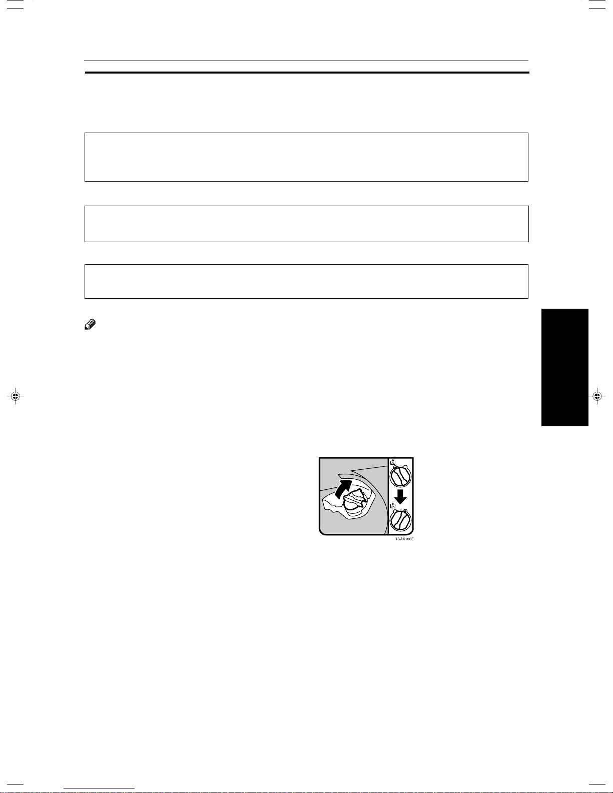
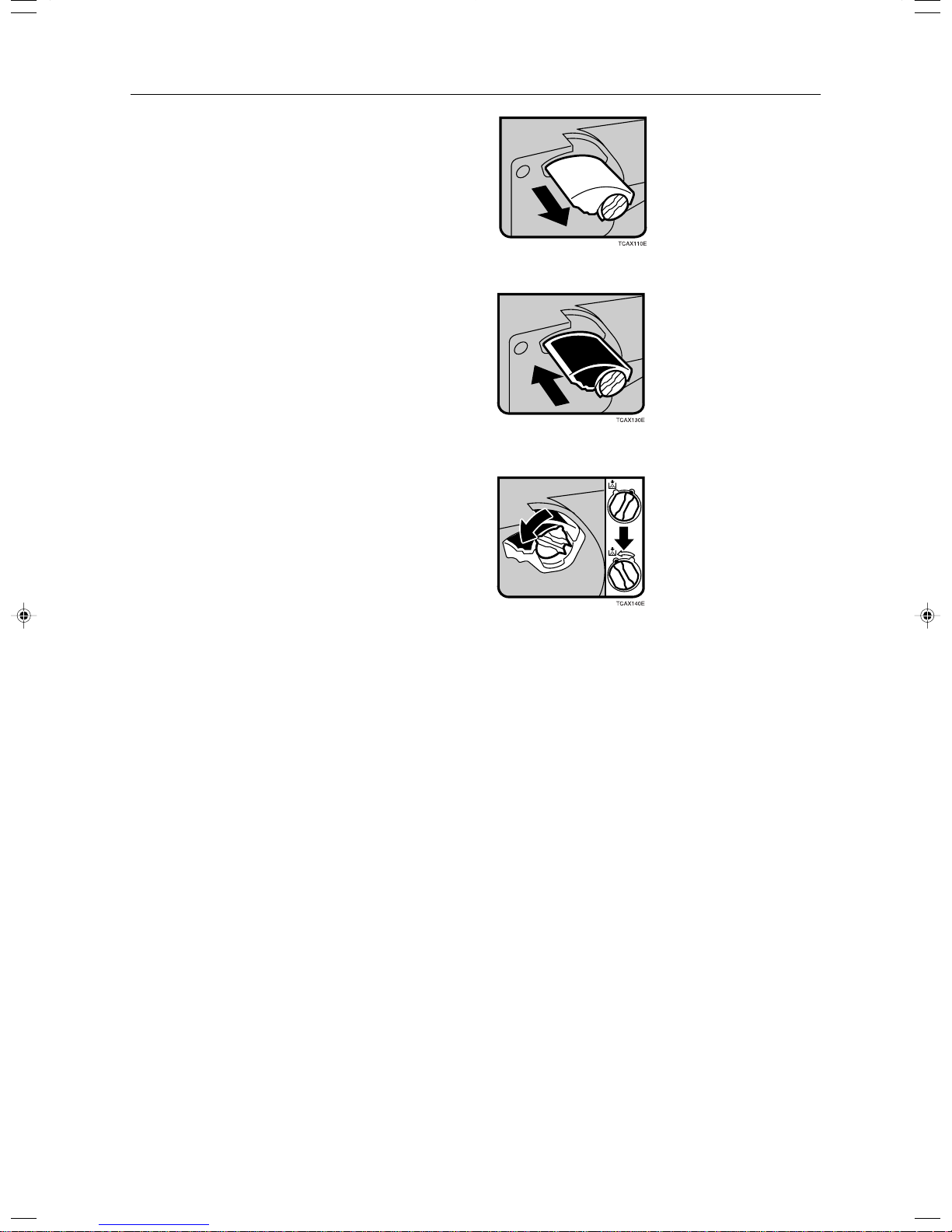
Open the front cover of the machine.
1
Turn the knob clockwise to the position shown
2
in the diagram.
175
Page 54
DAdding Toner
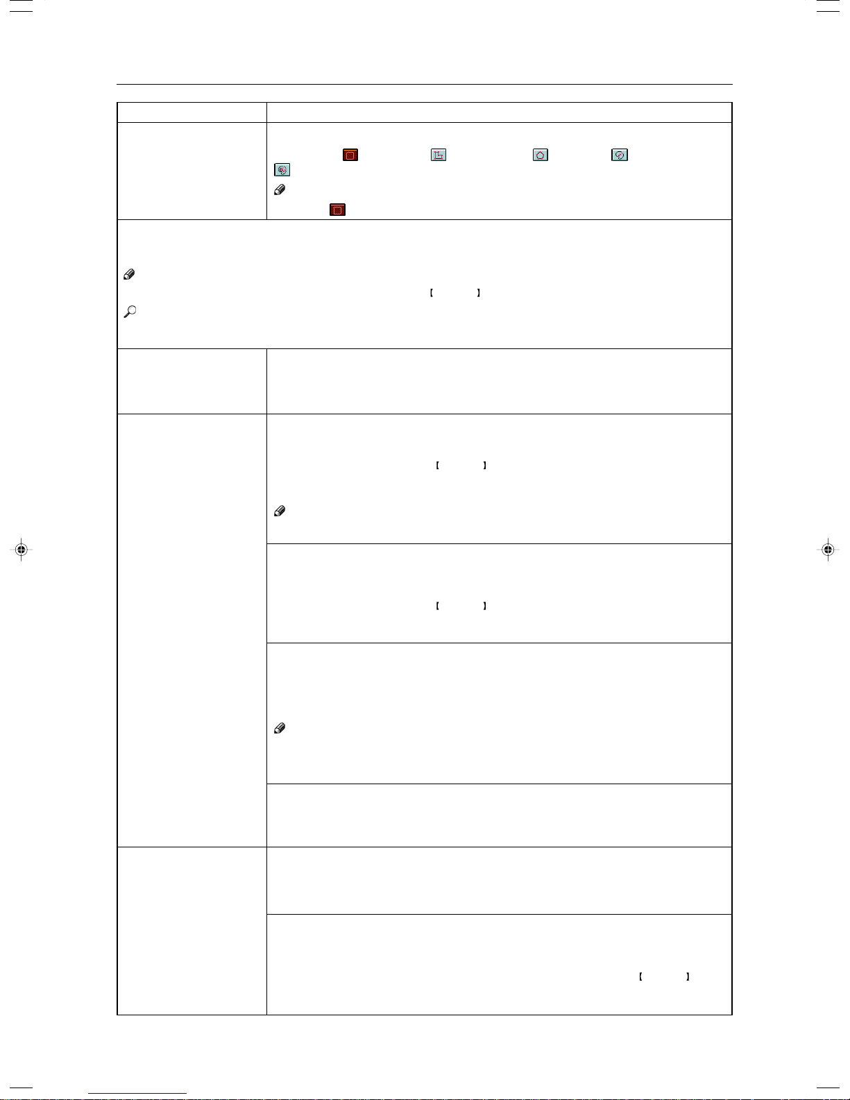
Pull out the toner container.
3
Push in the new toner container until it fits in
4
place.
Turn the knob back to the position shown and
5
close the front door.
176
Page 55

xClearing Misfeeds
xClearing Misfeeds
R
CAUTION
• When removing misfed paper, do not touch the fusing section because it could be very
n
Note
❐ When clearing misfeeds, do not turn off the operation switch. If you do, your copy settings are cleared.
❐ To prevent misfeeds, do not leave any torn scraps of paper within the machine.
❐ If paper misfeeds occur repeatedly, contact your service representative.
❐ When clearing misfeeds, make sure that all units and levers are returned to their original position and all covers are
closed.
❐ Do not touch originals in the document feeder when a paper misfeed occurs in the machine. If you do the machine
cannot determine which originals have been copied and which haven’t.
Check the Misfeed Location Display
The display shows the location of misfed paper.
hot.
Clearing Paper Misfeeds
When A, B, C, D or Z is Displayed:
Open the front cover of the machine.
1
You can find the sticker (with b at the top) ex-
2
plaining how to remove misfed paper inside the
front cover as shown in the illustration.
Remove misfed paper following the instructions
3
on the sticker.
Goes Wrong
What to do if Something
177
Page 56

xClearing Misfeeds
When R is Displayed:
Note
❐ This indicator is displayed only when your machine is equipped with the optional 20-bin sorter stapler.
Open the top cover of the sorter.
1
You can find the sticker (with b at the top) ex-
2
plaining how to remove the misfed paper on the
20-bin sorter stapler as shown in the illustration.
Remove the misfed paper following the instruc-
3
tions on the sticker.
When P is Displayed:
Note
❐ This indicator is displayed only when your machine is equipped with the document feeder.
You can find the sticker (with b at the top) ex-
1
plaining how to remove the misfed paper on the
document feeder as shown in the illustration.
Remove the misfed paper following the instruc-
2
tions on the sticker.
When U is Displayed:
Note
❐ This indicator is lit only when your machine is equipped with the optional large capacity tray.
You can find the sticker (with b at the top) ex-
1
plaining how to remove the misfed paper on the
large capacity tray as shown in the illustration.
Remove the misfed paper following the instruc-
2
tions on the sticker.
178
Page 57

dAdding Staples
dAdding Staples
R
CAUTION:
•
This machine has been tested for safety using this supplier’s parts and consumables. We
R
Note
❐ If you use a staple cartridge other than that recommended, staple failure or staple jams might occur.
Open the sorter stapler front cover, then pull the
1
R3 holder and pull out the stapler unit.
Push the cartridge forward to release it.
2
recommend you only use these specified supplies.
Pull out the cartridge.
3
Remove the empty refill in the arrow direction.
4
Align the arrow mark on the new refill with that
5
on the cartridge and push the new refill into the
cartridge until a click is heard.
Pull the ribbon out of the cartridge.
6
Goes Wrong
What to do if Something
179
Page 58

dAdding Staples
Place the cartridge in the staple unit.
7
Turn the cartridge backward until a click is heard.
8
Return the R3 holder into the original position.
9
Close the sorter stapler front cover.
0
180
Page 59

eRemoving Jammed Staples
eRemoving Jammed Staples
Note
❐ Staples might be jammed because of curled copies. In this case, try turning the copy paper over in the tray . If there is
no improvement, change to copy paper with less curl.
❐ After removing jammed staples, staples might not be ejected the first few times you try to use the stapler.
Open the sorter stapler front cover, then turn the
1
dial in the arrow direction until the staple unit
stops.
Push the R3 holder and pull out the staple unit.
2
Push the cartridge forward to release it.
3
Pull out the cartridge.
4
Push the lock on the right side of the phase plate
5
to open the phase plate.
Remove the jammed staple.
6
Goes Wrong
What to do if Something
181
Page 60

eRemoving Jammed Staples
Restore the phase plate in the original place until
7
a click is heard.
Place the cartridge in the staple unit.
8
Turn the cartridge backward until a click is heard.
9
Return the R3 holder into the original position.
0
Close the sorter stapler front cover.
!
182
Page 61

Changing the Machine’s Settings
Settings
Changing the Machine’s
183
Page 62

Changing Paper Size
Changing Paper Size
1st Tray Paper Size
Note
❐ Be sure to select the paper size with the user tools. Otherwise, misfeed might occur.
Reference
For paper sizes, weight , and the capacity that can be set in each tray, ☛ see page 238.
Make sure that the paper tray is not being used.
1
Pull out the paper tray until it stops.
2
Note
❐ Remove any remaining copy paper.
Adjust the back fence to the new paper size.
3
Square the paper and set it in the tray.
4
Note
❐ Shuffle the paper before setting it in the tray.
❐ Do not stack paper over the limit mark.
❐ Make sure the leading corners of the paper are un-
der the corners.
While pressing the release levers, slide the side
5
fences to the new paper size.
184
Page 63

Push the paper tray in until it stops.
6
Press the User Tools key.
7
Reference
For details, ☛ see below.
nd
2
and 3rd Tray Paper Size
Follow the steps 1 to 5 on page 184.
1
Adjust the tray size with the paper size selector
2
to the new paper size.
Note
❐ If you cannot find desired paper size on the paper
size selector, select the p, then press the User
key. ☛ see below.
Tools
Changing Paper Size
Push the paper tray in until it stops.
3
Changing Paper Size with the User Tools
Follow the steps 1 to 6 on page 184.
1
Press the User Tools key.
2
Settings
Changing the Machine’s
185
Page 64

Changing Paper Size
Press the [System Settings] key.
3
Press the [Next] key until Tray Paper Size is dis-
4
played.
Press the [Change] key to select the tray.
5
Select the paper size, then press the [OK] key.
6
Press the User Tools key to exit from the user
7
tools.
186
Page 65

User Tools
User T ools
Accessing the User Tools
This section is for the key operators in change of this machine. You can change or set the machine’s default
settings.
Note
❐ After using the tools, be sure to exit from the user tools.
Press the User Tools key.
1
Press the [System Settings] or [Copier Fea-
2
tures] key.
Settings
Changing the Machine’s
187
Page 66

User Tools
Select the desired user tools menu.
3
Note
❐ [Next] : Press to go to the next page.
❐ [Prev.] : Press to go back to the previous page.
Reference
User tools menu, ☛ see page 189.
Change the settings by following the instructions
4
on the panel display.
Note
❐ [Prev. Menu] key: Press to return to the previous
menu.
❐ [Cancel] key: Press to return to the previous menu
without changing any data.
Exiting from the User Tools
After changing the user tools settings, press the
1
User Tools key.
Note
❐ The settings are not canceled even if the operation
switch is turned off or the
pressed.
Clear Modes key is
188
Page 67

User Tools Menu
System settings
Panel Tone
Ready/Tone
Copy Count Display
Auto Timer
Control Panel Off Timer
System Reset Timer
Function Reset Timer
Tray Paper Size
Paper Tray Priority
Auto Tray Switching
Interleave Print
3 Side Full Bleed
Bypass Tray Custom Size
Display Color Setting
Key Operator Tools
AOF (Keep It On)
Menu
— — — — — — —
User Tools
See
page 191
page 191
page 191
page 191
page 191
page 191
page 191
page 192
page 192
page 192
page 192
page 192
page 193
page 193
page 193
page 193
Settings
Changing the Machine’s
189
Page 68

User Tools
Copier features
General
Features
Image
Adjustment
Duplex/
ADF/Sorter
Special Mode
Program(s)
Menu
Auto Paper Select Priority
ADS Priority (FC/Twin)
ADS Priority (B&W/SC)
Original Type Priority
Color Priority
Special Orig. Priority
Photo Type (Auto Text/Photo)
Photo Type (Photo)
Copy Reset Timer
Maximum Copy Quantity
Tone : Original on Platen
Front Side Margin Adjust.
Back Side Margin Adjust.
1→2 Duplex Auto Margin Adjust.
Magnification Setting
Initial Mode Setting
Show Editor Grid
Image Rotation
Add Margin in Repeat Image
Area Shape Priority
Key Operator Tools
Background Dens. of A.D.S. (FC/Twin)
A.C.S. Priority
Color Sensitivity
Process Black
Inkjet Output Mode Setting
Duplex Tray Auto Clear
SADF Auto Reset Timer
ADF Thin paper
ADF Mixed Sizes
ADF Auto Paper Select
Full Color Copy Sorting
Auto Sort Mode
Special Mode
— — — — — — —
Accessible Modes Setting
User Codes Setting
Counter Manager
— — — — — — —
— — — — — — —
— — — — — — —
See
page 194
page 194
page 194
page 194
page 194
page 194
page 194
page 194
page 194
page 195
page 195
page 195
page 195
page 195
page 195
page 195
page 195
page 196
page 195
page 196
page 196
page 196
page 196
page 197
page 197
page 197
page 197
page 197
page 197
page 197
page 198
page 198
page 198
page 198
page 198
page 198
Auto Color Calibration
Copy Mode/Printer Mode page 198— — — — — — —
190
Page 69

Setting You can Change with the User Tools (System Settings)
Reference
For how to access the user tools, ☛ see page 187.
System settings
User Tools
Menu
Panel T one
Ready/Tone
Copy Count Display
Auto Timer
Control Panel Off Timer
Description
The beeper (key tone) sounds when a key is pressed. This beeper can be turned on or
off.
Note
❐ Default: On
Choose whether the machine beeps when it becomes ready for a copy run after power
up.
Note
❐ Default: On
❐ When the “Panel Tone” is set to Off, the beeper does not sound even if the “Ready/
Tone” is set to On.
The copy counter can be set to show the number of copies made (Up), or the number
of copies remaining to be made (Down).
Note
❐ Default: Up
The machine turns itself off automatically to conserve energy after your job is finished,
after the selected time. This function called “Auto Off”. The time can be set from 1 to
120 minutes.
Note
❐ Default: 60 minutes
The machine enters Energy Saver mode automatically after your job is finished, after
the selected time. The time can be set from 10 to 990 seconds, or off. In Energy Saver
mode, the panel display turns off.
Note
❐ Default: On (60 seconds)
System Reset Timer
Function Reset Timer
The machine returns to its prioritized mode automatically after your job is finished, after
the selected time. This function is called “System Reset”. The time can be set from 10
to 990 seconds, or no system reset.
Note
❐ Default: On (60 seconds)
❐ You can specify the prioritized mode with the “Function Priority” user tool. ☛ See
above.
When the “Interleave Print” is set to On, the machine turns the default mode (Copier or
Printer) automatically after your job is finished, after the selected time. The time can be
set from 10 to 990 seconds.
Note
❐ Default: On (60 seconds)
❐ The optional printer is required to use this function.
Settings
Changing the Machine’s
191
Page 70

User Tools
Menu
Tray Paper Size
Paper Tray Priority
Auto Tray Switching
Interleave Print
Description
Select the size of the copy paper set in the paper tray.
Note
❐ If the specified paper size differs from the size of paper actually set in the paper tray, a
paper misfeed might occur because the paper size is not detected correctly.
Reference
For details, ☛ see page 238.
You can select the paper tray which will be selected as a default in the following
conditions:
• When the main power switch or operation switch is turned on.
• When System Reset or Auto Reset mode is turned on.
• When the
Clear Modes key is pressed.
• When the Auto Paper Select mode is not selected.
Note
❐ Default: Tray 1
If you load paper of the same size in two or more trays, the machine automatically
shifts another tray when the tray in use runs out of paper. You can set or cancel this
setting.
Note
❐ Default: Off
❐ This function is not available in Area Editing Mode.
By default, you can make the interrupt copies. You can cancel this setting.
Note
❐ Default: On
3 Side Full Bleed
When this mode is off, narrow margins on all 4 sides of the original are not copied.
1: 2 ± 2mm, 0.08" ± 0.08"
2: 2 ± 2mm, 0.08" ± 0.08"
3: 2 ± 2mm, 0.08" ± 0.08"
4: 4 ± 2mm, 0.16" ± 0.08"
When you turn it on, margins 1, 2 and 3 are copied.
Note
❐ Default: Off
❐ You cannot cancel the leading edge margin (margin 4).
192
Page 71

User Tools
Menu
Bypass Tray Custom Size
Description
You can register the non-standard size paper when you make copies with the bypass
tray.
1. Press the [Change] key.
2. Enter the horizontal size with the
3. Enter the vertical size with the
Note
Number keys, then press the [#] key.
Number keys, then press the [#] key.
❐ Adjustment value:
Metric version: Vertical: 100 - 330mm
Horizontal: 140 - 483mm
Inch version: Vertical: 3.9" - 13.0"
Horizontal: 5.5" - 19.0"
Display Color Setting
You can change the color of the display editor.
Note
❐ Default: Blue
Key Operator Tools
If you select “On”, only operators who know the key operator code can access the “Key Operator Tools” in the
System Settings and Copier Features.
Note
❐ Default : Off
❐ If you select “On”, you should register the key operator code.
AOF (Keep It On.)
Note
❐ For details about this function, contact your service representative.
Settings
Changing the Machine’s
193
Page 72

User Tools
Setting You can Change with the User Tools (Copier Features)
Reference
For how to access the user tools, ☛ see page 187.
General Features
Menu
Auto Paper Select Priority
ADS Priority (FC/Twin)
ADS Priority (B&W/SC)
Original Type Priority
Color Priority
Description
As a default setting, the Auto Paper Select is selected just after the machine is turned
on or when modes are cleared. You can cancel this setting.
Note
❐ Default: On
As a default setting, the Manual Image Density is selected in Full Color mode just after
the machine is turned on or when modes are cleared. You can cancel this setting so
that the Auto Image Density is selected.
Note
❐ Default: Manual
As a default setting, the Auto Image Density is selected in Black & White, Single Color,
and Twin Color mode just after the machine is turned on or when modes are cleared. You
can cancel this setting.
Note
❐ Default: Manual
You can select the original image type (Auto Original Type Select mode, Text/Photo
mode, Text mode, Photo mode, or Special Original mode) that is selected automatically
just after the machine is turned on or when modes are cleared.
Note
❐ Default: Text/Photo mode
You can select the color mode (Auto Color Select mode, Full Color mode, or Black & White mode)
that is selected automatically just after the machine is turned on or when modes are cleared.
Note
❐ Default: Auto Color Select mode
Special Orig. Priority
Photo Type (Auto Text/
Photo)
Photo Type (Photo)
Copy Reset Timer
194
You can select the special original type (Highlight Pen, Inkjet Output, or Map) that is
selected automatically just after the machine is turned on or when modes are cleared.
Note
❐ Default: Highlight Pen
You can select the photo type (
Press Print, Glossy Photo, or 2nd Generation) in Auto Text/Photo mode that is selected automatically just after the machine is
turned on or when modes are cleared.
Note
❐ Default: Press Print
You can select the photo type (
Press Print, Glossy Photo, or 2nd Generation) in Photo mode that is selected automatically just after the machine is turned on or
when modes are cleared.
Note
❐ Default: Press Print
The machine returns to its initial condition automatically after your job is finished. The
time can be set from 10 to 990 seconds, or no copy reset.
1. Select [On] or [Off] keys.
2. When you select [On], enter the time with the
Note
Number keys. Then, press the [#] key .
❐ Default: On (60 seconds)
Page 73

User Tools
Menu
Maximum Copy Quantity
Tone : Original on Platen
Front Side Margin Adjust.
Back Side Margin Adjust.
1→2 Duplex Auto Margin
Adjust.
Description
The maximum copy quantity can be set from 1 to 999.
Note
❐ Default: Off
The beeper (key tone) sounds when you forgot to remove originals after copying.
Note
❐ Default: Off
❐ When the “Panel Tone” is set to Off, the beeper does not sound even if the “Original
Tone” is set to On.
You can adjust the front side margin direction and width that is selected as a default in
Front Side Margin Adjust. mode.
Note
❐ Default:
• Metric version: left/right 0mm
• Inch version: left/right 0"
You can adjust the back side margin direction and width that is selected as a default in
Back Side Margin Adjust.
Note
❐ Default:
• Metric version: left/right 0mm
• Inch version: left/right 0"
When you use 1 Sided → 2 Sided mode, the machine set the back side margin
automatically.
Note
❐ Default: Off
Magnification Setting
Initial Mode Setting
Show Editor Grid
(Only for Edit type)
Image Rotation
Add Margin in Repeat
Image
Up to 2 reproduction ratios which you frequently use can be registered.
1. Press the [Setting] key.
2. Select the [User Ratio 1] or [User Ratio 2] key.
3. Enter your desired ratio with the
Number keys.
Then press the [OK] key.
You can set the machine to recall program setting when the machine is turned on or
when modes are cleared.
Note
❐ Default: Normal
You can turn the grid snap on or off in the display editor. The grids may help you to
mark a right angle shape.
Note
❐ Default: Off
When you use the same size and different direction copy paper, the machine rotates
the original image 90
Note
o
.
❐ Default: On
You can select add margin or not.
Note
❐ Default: On
Settings
Changing the Machine’s
195
Page 74
User Tools
Menu
Area Shape Priority
Description
When you designate areas, you can select the first designated shape.
1. Select the
(Rectangle), (R.A.Polygon), (Polygon), (Closed Loop), or
(Multi. Closed Loop) key.
Note
❐ Default: (Rectangle) key
Key Operator Tools
Use these tools to manage use of the machine.
Note
❐ Enter a previously registered key operator code with the Number keys.
Reference
About the key operator code, ☛ see page 193.
Accessible Modes Setting
You can assign user codes to each color mode. Operators must input their user codes
before using each color mode (Full color, Black & White, Single, Twin Color).
The machine keeps count of the number of copies made under each user code.
1. Select your desired color mode.
User Codes Setting
Program
You can register the user codes.
1. Press the [Program] key.
2. Enter the user code with the
Number keys. Then press the [#] key.
3. Select the color mode from [Full Color], [Black & White], [Single], or [Twin Color]
key.
Note
❐ You can up to 200 user codes.
Counter Manager
Change
You can change the user codes.
1. Press the [Change] key.
2. Select the user code.
3. Enter the user code with the
Number keys. Then press the [#] key.
4. Select the color mode from [Full Color], [Black & White], [Single], or [Twin Color]
key.
Clear
You can clear the user codes.
1. Press the [Clear] key.
2. Select the user code that you want to clear.
3. If you want to clear the all user codes of the page, press the [Select All] key.
Note
If you want to change the [Select All], press the [Clr All Select] key.
4. Press the [OK] key.
5. Press the [Yes] key.
Delete All
You can delete the all registered user codes.
1. Press the [Delete All] key.
2. Press the [Yes] key.
Counter List Print
You can print data for all user codes.
1. Press the [Counter List Print] key.
2. Press the [Print Start] key.
Reset Counters
You can check the number of copies made using each user code. Also, you can clear
each code’s counter.
1. Press the [Reset Counters] key.
2. Input the user code you want to check its number of copies with the
Number keys.
3. Press the [OK] key.
4. Press the [Yes] key.
196
Page 75

User Tools
Menu
Counter Manager
Image Adjustment
Menu
Background Dens. of
A.D.S. (FC/Twin)
A.C.S. Priority
Color Sensitivity
Description
Delete All
You can reset the counter for all user codes.
1. Press the [Delete All] key.
2. Press the [Yes] key.
Description
The Auto Image Density levels in Full Color mode can be made lighter or darker (5
levels).
Note
❐ Default: level 3
You can select color images or black & white images that are priority detected in Auto
Color Select mode.
Note
❐ Default: Full Color
When in Color Erase or Color Conversion mode, the function can be made more or
less sensitive to the color to be erased or converted. It can be adjusted within 5 levels
(“Narrow” to “Wide”).
For example, if red is selected as the color to be erased or converted, “Narrow” will
result in only red being erased or converted, and “Wide” will result in other colors close
to red being erased or converted.
Note
❐ Default: level 3
Process Black
Inkjet Output Mode
Setting
Duplex/ADF/Sorter
Menu
Duplex Tray Auto Clear
SADF Auto Reset Timer
When copying in full color, 4 colors (Yellow, Magenta, Cyan, and Black) are used by
default. You can change this so that only 3 colors (Yellow, Magenta, and Cyan) are
used.
Note
❐ Default: 4 colors
You can select the type of image adjustment for the Inkjet Output Mode from the below.
If you want to emphasis yellow, select 1.
If you want to emphasis red and yellow, select 2.
If you want to emphasis red and blue, select 3.
Note
❐ Default: 1
Description
When making two-sided copies from one-sided originals, if the last original is an odd
page, the last copy will be automatically delivered with the reverse side blank. You can
cancel this setting.
Note
❐ Default: On
When you set one original at a time in the document feeder, the Auto Feed indicator
lights for a selected time after an original is fed to show that the document feeder is
ready for another original. The time can be set from 1 second to 99 seconds.
Note
❐ Default: 5 seconds
Settings
Changing the Machine’s
197
Page 76

User Tools
Menu
ADF Thin paper
ADF Mixed Sizes
ADF Auto Paper Select
Full Color Copy Sorting
Auto Sort Mode
Description
Use when changing the type of originals to be fed. Select this function to avoid damaging thin originals (40 - 52g/m
Note
2
, 11-14 lb) set in the document feeder.
❐ Default: Off
By default, you cannot set originals of different sizes at one time in the document
feeder. You can cancel this setting.
Note
❐ Default: Off
❐ If you select [On], the copying speed will be reduced.
❐ When setting different length originals, all originals must be flush with the back fence
of the document feeder.
❐ Smaller size originals might be skewed a little.
By default, the Auto Paper Select is selected when you set originals in the document
feeder. You can cancel this setting.
Note
❐ Default: On
You can disable sorting, stacking, or stapling in Full Color mode to maximize quality of
full color copies.
Note
❐ Default: Off
You can have the machine select Sort mode automatically when you insert two or more
originals in the document feeder and make two or more copies from each original.
Note
❐ Default: On
Special Mode Program(s)
Special Mode
Use to recall the special modes set by your service representative.
Auto Color Calibration
Copy Mode/Printer Mode
When the tone of a specific color is strong or the color tone of copies is different from
that of originals, perform this function. This function adjusts the balance of the 4 basic
colors.
1. Press the [Auto Color Calibration] key.
2. If your machine has the printer option installed, select Copy Mode or Printer Mode.
Then press the [On] key.
3. Press the [Print Start] key.
Note
❐ The test pattern is delivered to the copy tray.
4. Set the test pattern on the exposure glass (platen glass). Then press the [Scan
Start] key.
Limitation
❐ You cannot set the test pattern in the document feeder.
Note
❐ To return to the previous setting, press the [Prev. Setting] key.
198
Page 77

Maintaining Y our Machine
Where to Put Your Machine
Do’s and Don’ts
Remarks
Use and Storage of Supplies
Others
199
Page 78

Maintaining Y our Machine
Maintaining Y our Machine
If the exposure glass (platen glass), platen cover or document feeder belt is dirty, you might not be able to
make copies as you want. Clean them if you find them dirty.
Note
❐ Do not use chemical cleaner or organic solvent, such as thinner or benzene. If they get into the machine or melt plastic
parts, a failure might occur.
❐ Do not clean parts other than those specified in this manual. Such parts should be cleaned by your service representa-
tive.
❐ Wipe the machine with a soft, damp cloth. Then wipe it with a dry cloth to remove the water.
Exposure Glass (Platen Glass)
Platen Cover
Document Feeder
TRSR130E
TRSR140E
200
TRSR150E
Page 79

Where to Put Your Machine
Where to Put Your Machine
Machine Environment
Y our machine’s location should be carefully chosen because environmental conditions greatly affect its performance.
Optimum environmental conditions
R
CAUTION:
•Keep the machine away from humidity and dust. A fire or an electric shock might occur.
m
R
CAUTION:
•Do not place the machine on an unstable or tilted surface. If it topples over, it cause injury.
•If you use the machine in a confined space, make sure there is a continuous air turnover.
o
❐ Temperature: 10 – 32°C, (50 – 89.6°F)(humidity to be 54% at 32°C, 86°F)
❐ Humidity: 15 – 80% (temperature to be 27°C, 80.6°F at 89.6%)
❐ A strong and level base.
❐ The machine must be level within 5mm, 0.2" both front to rear and left to right.
❐ To avoid possible built-up ozone, make sure to locate this machine in a large well ventilated room that has an air
turnover of more than 30m
3
/hr/person.
Environments to avoid
❐ Locations exposed to direct sunlight or strong light (more than 2,000 lux).
❐ Locations directly exposed to cool air from an air conditioner or heated air from a heater. (Sudden temperature changes
might cause condensation within the machine.)
❐ Places where the machine might be subjected to frequent strong vibration.
❐ Dusty areas.
❐ Areas with corrosive gases.
Others
201
Page 80

Where to Put Your Machine
Power Connection
R
WARNING:
• Only connect the machine to the power source described on the inside front cover of this
m
R
WARNING:
m
R
WARNING:
o
R
CAUTION:
r
manual.
• Avoid multi-wiring.
• Do not damage, break or make any modifications to the power cord. Do not place heavy
objects on it, pull it hard or bend it more than necessary. These actions could cause an
electric shock or fire.
• Do not plug or unplug the power cord with your hands wet. Otherwise, an electric shock
might occur.
• Make sure the wall outlet is near the machine and freely accessible so that in event of an
emergency it can be unplugged easily.
•When you move the machine, unplug the power cord from the wall outlet to avoid fire or electric
shock.
•When the machine will not be used for a long time, unplug the power cord.
R
CAUTION:
•When you pull out the plug from the socket, grip the plug to avoid damaging the cord and causing
t
• When the main power switch is in the Stand-by positions, the optional anti-condensation heaters are on. In
• When you unplug the power cord, the anti-condensation heaters turn off.
• Make sure the plug is firmly inserted in the outlet.
• Voltage must not fluctuate more than 10%.
fire or electric shock.
case of emergency, unplug the machine’s power cord.
Access to Machine
Place the machine near the power source, providing clearance as shown.
1
2
4
3
TRSR120E
1. Rear: more than 10cm, 4.0"
2. Right: more than 45cm, 17.8"
3. Front: more than 55cm, 21.7"
4. Left: more than 48cm, 18.9"
Note
❐ For the required space when options are installed, please contact your service representative.
202
Page 81

Do’s and Don’ts
Do’s and Don’ts
R
CAUTION:
• When you move the machine, unplug the power cord from the wall outlet to avoid fire or electric
r
• Do not touch areas on or around the fusing unit. These areas get hot.
• After making copies continuously, you might feel the exposure glass is heated. But this is not a malfunction.
• You might feel warm around the ventilation hole. This is caused by exhaust air, and not a malfunction.
• Do not turn off the operation switch while copying. When turning off the operation switch, make sure that copying is
• The machine might fail to produce good copy images if there should occur condensation inside caused by tempera-
• Do not open the covers of machine while copying. If you do, misfeeds might occur.
• Do not move the machine while copying.
• If you operate the machine improperly or a failure occurs on the machine, your machine settings might be lost. Be
• Supplier shall not be liable for any loss or damages resulting from a failure on the machine, loss of machine settings,
shock.
•When the machine will not be used for a long time, unplug the power cord.
completed.
ture change.
sure to take a note of your machine settings.
and use of the machine.
Others
203
Page 82

Remarks
Remarks
Copier
❐ Be careful not to move the original during the scanning process.
❐ To avoid problems caused by curled copies, try turning over the paper stack in the paper tray. If there is no improve-
ment, change to copy paper with less curl.
❐ Load paper with the copy side
If there is no improvement, change to copy paper with less curl.
❐ As a default setting, narrow margins on all four sides will not be copied as shown in the illustration.
down in the paper trays. If copies are curled, try turning the copy paper over in the tray.
1: 2 ± 2mm, 0.08"± 0.08"
2: 2 ± 2mm, 0.08"± 0.08"
3: 2 ± 2mm, 0.08"± 0.08"
4: 4 ± 2mm, 0.16"± 0.08"
204
Page 83

Use and Storage of Suplies
Use and Storage of Supplies
Copy Paper
❐ Copy paper of the types or in the conditions listed below are not recommended for this copier.
• Folded, curled, creased, or damaged paper
• Torn paper
• Perforated paper
• Paper with conductive or low electrical resistance coating such as carbon or silver coating
• Thermal paper, art paper
• Thin paper that has low stiffness
• Damp paper
• Wavy paper
• Stapled paper
❐ Never use ink-jet printer paper to prevent failure.
❐ Use a proper type OHP transparency and set it in correct direction to prevent failure.
❐ Fan copy paper and OHP transparencies to get air between the sheets before loading.
❐ Do not touch copy paper if your fingers are wet or oily; finger prints may appear on the copy.
❐ Load paper with the copy side down in the paper trays. If copies are curled, try turning the copy paper over in the tray.
If there is no improvement, change to copy paper with less curl.
❐ When copying on rough surface paper, the copy image may be light.
❐ When setting paper thinner than 64g/m
in the figure below. The paper is divided into the vertical and horizontal types depending on the texture flow direction.
If you set thin paper or translucent paper in the reverse direction, a paper jam might occur. Since A3, B4, 11" × 17", and
8
1/2" × 14" sizes of thin paper are set in the lengthwise direction in this machine, they must be of the vertical type.
2
, 17 lb or translucent paper in the paper trays or bypass trays, set it as shown
Vertical
type
Horizontal
type
Texture flow Setting paper Setting paper
in the paper trays in the bypass tray
GCYOSI1E
GCYOSI2E
Others
205
Page 84

Use and Storage of Suplies
Paper Storage
Paper should always be stored properly. Improperly stored paper might result in poor image reproduction,
creased copies, and paper misfeeds. Generally, avoid curling and absorption of moisture.
❐ Avoid storing paper in humid areas. Under high temperature and high humidity, or low temperature and low humidity
conditions, store paper in a vinyl bag.
❐ Do not store paper where it will be exposed to heat.
❐ Store on a flat surface.
❐ Use older stock first.
❐ Do not lay heavy objects on paper.
❐ Keep open reams of paper in the package, and store as you would unopened paper.
Toner Storage
❐ Store in a cool, dark place.
❐ Never store toner where it will be exposed to heat.
❐ Do not lay heavy objects on toner container.
206
Page 85

Projector Unit Operation
Operation
Projector Unit
207
Page 86

Guide to Components
Guide to Components
1. Power cord
Plug the power cord into a wall outlet.
2. Holder slot
Set the holder here.
3. Filter slot
Insert the P or N filter here.
4. Film cover
T o protect the slots from dust, close it when you
are not using the projector.
5. Mirror unit release lever
Slide this to the left when opening the mirror
unit.
6. Focusing lever
Adjusting the focus with this lever when you
make copies from a glass mount film.
7. Power switch
Switches the power on or off.
8. Mirror unit
Reflects the light from the projector to the copier.
9. Fresnel lens
Pull this up when setting film on the exposure
glass.
10. Lens cover
To protect the lens from dust, close it when you
are not using the projector.
11. Accessory box
Accessories should be stored here.
12. Holder lever
Use to set the holder into the holder slot.
208
Page 87

Guide to Components
2
1
3
P
N
6
4
5
TRSR0B0E
1. Lock levers
Use to fix the film after setting it in the holder.
2. Film holders
Set 35mm film in one of these holders.
• Slide holder: Set mounted positive films in this holder. (This holder is covered with glass.)
• Film strip holder: Set negative or positive strip film and base film here.
• Glass mount film holder: Set the positive glass mount films in this holder. (This holder is covered with
glass.)
3. Slide mount
Use to make a base film slide.
4. Base film slides
Use them when performing shading with Negative film.
5. Filters (P = Positive, N = Negative)
One of them should be set in the filter slot.
6. Blower brush
Use to clean the lens or glass.
Operation
Projector Unit
209
Page 88

Guide to Components
Master film position sheet
Make a copy of the master sheet onto type C film
and use the copy to position the film correctly on the
exposure glass.
Make a copy from the original sheet, cut around the
surrounding margin on the dotted lines, and cut away
the center part corresponding to the size of the film
to be copied.
Keep the master film position sheet.
210
Page 89

Before Operating the Projector
Before Operating the Projector
Available Films and Setting
Film type / size
35mm mount film
35mm glass mount film ✕✕ 앪 ✕
35mm strip film ✕ 앪 ✕ 앪
60 × 45mm ✕✕ ✕앪
60 × 60mm ✕✕ ✕앪
60 × 70mm ✕✕ ✕앪
60 × 80mm ✕✕ ✕앪
60 × 90mm ✕✕ ✕앪
4" × 5" (101.6 × 127mm) ✕✕ ✕앪
Setting location
Slide film Slide strip Glass mount Exposure glass
holder holder film Holder (platen glass)
앪 ✕✕✕
Operation
Projector Unit
Maximum size
(142 × 210mm, 5.5" × 8.2")
✕✕ ✕앪
Note
❐ Do not use the same film for more than 30 minutes.
❐ Do not store film in rooms where the temperature is more than 30°C, 86°F.
❐ For valuable images, we recommend copying from duplicates.
❐ When using a film strip, be sure to take it out from the film protection sheet.
211
Page 90

Before Operating the Projector
GCFPRE4E
7.8"
133 mm
200 mm
5.2"
GCFPRE2E
1.3"
23 mm
34 mm
0.9"
About Copying
When setting mount films and strip films in the film holders
Mount films
(using the slide holder)
Area of film that can be
copied
21.5 mm
0.8"
33 mm
1.2"
GCFPRE1E
Copy size
(copying full size)
124 mm
4.8"
195 mm
7.6"
GCFPRE3E
When setting wide films with the film position sheets
Narrow margins on all four sides will not be copied as shown in the illustration.
Film size A B
×
45mm 61.3mm 48mm
60
60
×
60mm 61.3mm 64mm
60
×
70mm 61.3mm 77mm
×
80mm 61.3mm 84mm
60
60
×
90mm 61.3mm 93mm
4"
×
5" 100mm 125mm
Maximum 142mm 210mm
(using the film strip holder)
Strip films
212
Page 91

Before Operating the Projector
Notes for Operation
❐ First, you must perform shading to get the projector to register the condition of the film. This way, the projector can
adjust the light intensity automatically while copying.
❐ If you press the Clear Modes key or [Cancel] key while using Projector function, all operations with the Projector will
be canceled.
❐ You can adjust the color tone and color density manually.
❐ This projector has an automatic focus function, but if you use the glass mount film holder, adjust the focus manually.
❐ Do not forget to turn off the power switch of the projector when you are not using it.
❐ Do not obstruct the light path from the projector. If the light path is obstructed, the image might not match the original.
❐ This shading adjustment is very sensitive, so after the shading operation the mirror unit must be left perfectly still. Do
not move it or allow vibrations to interfere with it. If this happens during copying, lines might appear on the copy. In that
case, you must perform shading again.
❐ If you need to open and close the doors (to clear a jam or add toner), we recommend that you perform shading again
afterwards.
❐ Avoid multi-wiring.
Operation
Projector Unit
213
Page 92

How to Copy from Film
How to Copy from Film
The outline procedure for making copies is given below. Refer to the rest of this section for details of each
step.
Position the projector. ☛ See page 215.
∨
Prepare the film. ☛ See page 216.
∨
Select the film type and perform shading. ☛ See page 220.
∨
Adjust color, density and focus. ☛ See page 228.
∨
Select modes. ☛ See page 231.
∨
Press the Start key.
∨
Choose next job. ☛ See page 232.
214
Page 93

Positioning the Projector
Positioning the Projector
Note
❐ Do not touch the fresnel lens or the glass on the mirror unit. Fingerprints or dirty parts might appear on the copy. If the
fresnel lens becomes dirty, wipe it. ☛ See page 236.
Plug the projector into the wall outlet.
1
Turn on the main switch of the projector.
2
Operation
Projector Unit
Lift the platen cover or the document feeder and
3
lower the projector lens cover.
Place the mirror unit so that the unit’s position
4
holes fit over the projector’s positioning pins.
Note
❐ Please be careful not to scratch the exposure glass
when setting the mirror unit on it.
Slide the mirror unit release lever in the direc-
5
tion of the arrow and open the mirror unit cover.
1
TRSR0C0E
1. Lens cover
1
2
TRSR0D0E
1. Mirror unit
2. Positioning pins
1
1. Mirror unit release lever
TRSR0E0E
215
Page 94

Preparing the Film
Check this table to find out the key you should use for your film type.
Preparing the Film
35mm
Others
Max. Size:
142 × 210mm
5.5" × 8.2"
Film Type
Slide
(Mount)
Slide
Positive (Glass
Mount)
Strip Film
Negative Strip Film
Positive
Negative
Filter
“P”
(Positive Filter)
“P”
(Positive Filter)
“P”
(Positive Filter)
“N”
(Negative Filter)
“P”
(Positive Filter)
“N”
(Negative Filter)
Base
Film
✕
✕
✕
앪
✕
앪
Positioning
Sheet
✕
✕
✕
✕
앪
앪
Slide Holder
Glass Mount
Film Holder
Film Strip
Holder
Film Strip
Holder
(Place on the
exposure glass)
(Place on the
exposure glass)
Note
❐ When performing shading, you must set a filter that matches that type of film you will copy.
❐ Use an “N” filter for Negative films and a “P” filter for Positive films.
Holder
✕
✕
Key To
Select
35mm Sides
Positive
35mm Sides
Positive
35mm Sides
Positive
35mm Strip
Negative
Positive
Film on
glass
Negative
Film on
glass
216
Page 95

Preparing the Film
Selecting the Base Film (If Needed)
Note
❐ When you use negative film for copying, use that film’s appropriate base film for shading.
Confirm the manufacture, model name, and ASA
1
rating of the film you want to use.
Select a base film suitable for the film to copy.
2
Note
❐ The following base film slides have been prepared as accessories.
• For FUJICOLOR (registered trademark of FUJI PHOTO COMPANY LIMITED.)
• For AGFA (registered trademark of AGFAGEVAERT AG.)
• For KODAK (registered trademark of EASTMAN KODAK COMPANY.)
❐ If you use film that does not have suitable base film, you should make the base film yourself. ☛ See page 234.
Open the film strip holder and set the base film
3
in the film strip holder.
Note
❐ The base film must be set sideways in the strip holder.
❐ There is no difference between both sides of the base
film.
Operation
Projector Unit
Close the holder and lock it as shown in the il-
4
lustration.
1
TRSR0H0E
1: Base film
217
Page 96
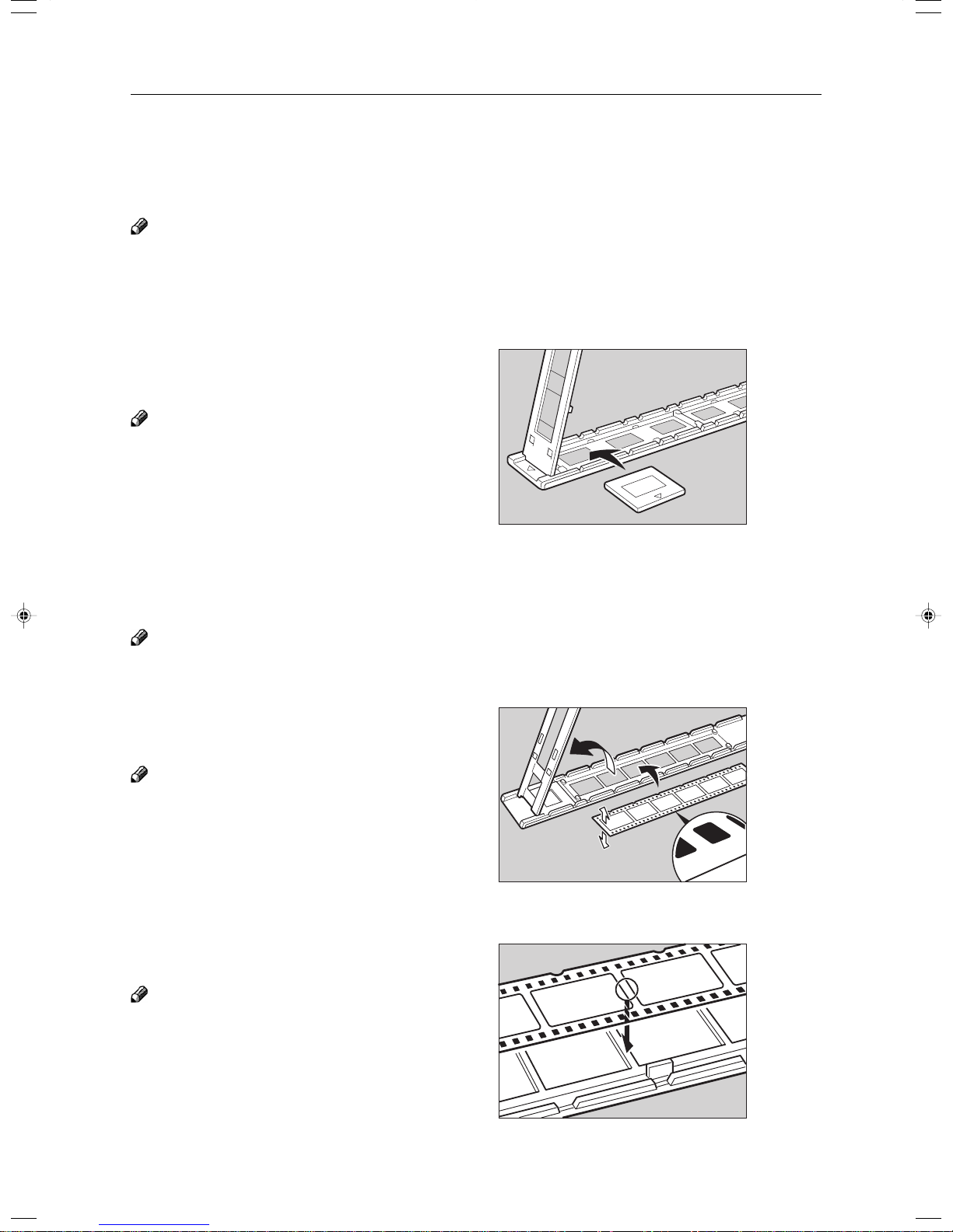
Preparing the Film
Setting Films in the Holder (If Needed)
Check which type of holder you should use. ☛ See page 216.
Slide Holder/Glass Mount Film Holder
Note
❐ The slide holder is covered with glass. Set the mount films in the slide holder.
❐ The glass mount film holder is not covered with the glass. Set the glass mount films (covered by glass) in the glass
mount film holder.
❐ Positive films are usually set in a slide mount or glass mount. If you use positive film not set in a mount, set it in the film
strip holder. ☛ See below.
Open the cover of the slide holder or glass mount
1
film holder, and set the slides in the holder one
by one.
Note
❐ Set the front side of the film face down when setting
in the slide holder or glass mount film holder.
❐ When setting in the slide holder, make sure that all
slides are aligned with the glass of the slide holder
cover.
Close the holder and lock it.
2
TRSR0L0E
Film Strip Holder
Note
❐ Negative film usually come in stripes.
❐ Follow this procedure for positive strip film as well.
Open the film strip holder. Put the front side of
1
the film face down and set it in the film strip
holder.
Note
❐ When setting film, leave the base film in the film strip
holder. This is convenient when performing shading
again.
Adjust the position of the film.
2
Note
❐ Do not touch the image parts of the film when adjust-
ing.
1: Back
2: Front
1
2
5
TRSR0K0E
Close the film strip holder and lock it .
3
218
TRSR0W0E
Page 97

Preparing the Film
Cutting the Film Position Sheet (If Needed)
If you do not use the holders and position the film on the exposure glass, a positioning sheet is required.
Make a copy of one of the positioning sheet originals and use it to make your own sheet. Cut a hole the size
of the film from the center of the copy, then crop the sheet by cutting around the dotted lines.
Operation
Projector Unit
219
Page 98

Selecting the Film Type and Performing Shading
Selecting the Film Type and Performing Shading
The procedures are different depending on the type of film.
Press the Special Accessory Key.
1
Select the film type.
2
Follow the shading procedure appropriate to your
3
film type — see below.
Film Type
35mm
Others Max. Size
Positive
Negative
Positive
Negative
Slide (Mount)
Slide (Glass Mount)
Strip Film
Strip Film
Key To Select
[35 mm Slides Positive]
[35 mm Slides Positive]
[35 mm Slides Positive]
[35 mm Strip Negative]
[Positive Film on glass]
[Negative Film on glass]
Go to page…
Page 221
Page 221
Page 221
Page 223
Page 222
Page 226
220
Page 99

35mm Slides Positive
Press the [Shading] key.
1
Open the film cover and insert the “P” (Posi-
2
tive) filter firmly in the left slot as shown in the
illustration.
Note
❐ Be careful to insert the filter as shown, not the other
way around.
❐ Before going to the next step, make sure that fresnel
lens is lowered in position.
Selecting the Film Type and Performing Shading
1
Operation
Projector Unit
Press the [Shading] key.
3
❐ The machine will start shading automatically.
Set the film (slide or strip) in the holder.
4
Reference
Regarding setting the film, ☛ see page 218.
While pressing the holder lever to the left, insert
5
the holder in the right slot.
1: Filter
TRSR0F0E
Adjust the holder by sliding it up and down to
6
position the correct frame for copying.
TRSR0Y0E
2
1
TRSR0N0E
221
Page 100

Selecting the Film Type and Performing Shading
If needed, adjust the color, density, or focus.
7
Reference
For details, ☛ see page 228.
If needed, select the copier modes.
8
Reference
For details, ☛ see page 231.
Press the Start key.
9
Choose your next job.
0
Reference
For details, ☛ see page 232.
Positive Film on Glass
Press the [Shading] key.
1
Insert the “P” (Positive filter) in the left slot as
2
shown in the illustration.
Note
❐ Be careful to insert the filter as shown, not the other
way around.
Cut the positioning sheet to match the film size.
3
Reference
Regarding the positioning sheet, ☛ see page 219.
Place the positioning sheet under the mirror unit
4
(on the exposure glass).
Note
❐ Place the marked corner of the film position sheet at
the rear left corner of the exposure glass.
❐ Before going to the next step, make sure that the
fresnel lens is lowered in position.
1
TRSR0F0E
1: Filter
1
222
TRSR0G0E
1: Positioning sheet
 Loading...